EP2572136B1 - Single point lubricator - Google Patents
Single point lubricator Download PDFInfo
- Publication number
- EP2572136B1 EP2572136B1 EP10722942.9A EP10722942A EP2572136B1 EP 2572136 B1 EP2572136 B1 EP 2572136B1 EP 10722942 A EP10722942 A EP 10722942A EP 2572136 B1 EP2572136 B1 EP 2572136B1
- Authority
- EP
- European Patent Office
- Prior art keywords
- insert
- collar
- notch
- release position
- catch
- Prior art date
- Legal status (The legal status is an assumption and is not a legal conclusion. Google has not performed a legal analysis and makes no representation as to the accuracy of the status listed.)
- Active
Links
Images

Classifications
-
- F—MECHANICAL ENGINEERING; LIGHTING; HEATING; WEAPONS; BLASTING
- F16—ENGINEERING ELEMENTS AND UNITS; GENERAL MEASURES FOR PRODUCING AND MAINTAINING EFFECTIVE FUNCTIONING OF MACHINES OR INSTALLATIONS; THERMAL INSULATION IN GENERAL
- F16N—LUBRICATING
- F16N11/00—Arrangements for supplying grease from a stationary reservoir or the equivalent in or on the machine or member to be lubricated; Grease cups
- F16N11/10—Arrangements for supplying grease from a stationary reservoir or the equivalent in or on the machine or member to be lubricated; Grease cups by pressure of another fluid
Definitions
- the present invention relates to a device for gas pressure-driven lubrication of a lubrication point.
- an automatic lubrication device is advantageous.
- lubrication devices that comprise a pump of some kind, a lubricant reservoir such as a grease container and a control unit that dispenses a predefined amount of lubricant to the lubrication point at predetermined time intervals.
- a pump of some kind a lubricant reservoir such as a grease container
- a control unit that dispenses a predefined amount of lubricant to the lubrication point at predetermined time intervals.
- Such a system is rather complicated and the size is often rather large.
- Another type of automatic lubrication device is a self-contained grease container which somewhat resembles a grease cartridge.
- a grease container comprises a gas generating cell and a compartment of grease which dispenses grease from the compartment to the lubrication point.
- the gas generation may be based on a dry cell that produces gas in an electrochemical way.
- the amount of generated gas is controlled by the current flowing from a gas generating electrode to a counter electrode.
- the generated gas will build up a pressure inside the container which in turn causes a piston to dispense grease from a lubricant opening.
- Such a lubrication device is known from US 5,012,897 .
- two gas cells are connected to each other through a fixed resistor by an intermediate spring.
- the spring By screwing the top part of the device into the container lid, the spring connects the two cells such that the electric circuit closes and gas starts to generate.
- the top part may be unscrewed somewhat in order to disconnect the electrical circuit, and by unscrewing the top part completely, new gas cells may be fitted.
- One disadvantage of being able to replace the gas cell in an easy way is that the manufacturer of the lubrication device cannot guarantee a proper function of the lubrication device since it is possible to tamper with the gas cell.
- By replacing the gas cell there is a possibility for the user to insert a used gas cell with a reduced capacity, which would lead to a reduced life of the lubrication device compared with what was expected.
- DE 102004 013594 describes a lubrication device in which the lid may be used to set the amount of dispensed lubricant.
- the lid of the container is provided with a rotatable part comprising a potentiometer element.
- the rotatable part is provided with protrusions that stop the rotatable part from being removed once it is in position.
- the lid is fixedly attached to the container. In this way, the container may not be refilled and the gas cell may not be removed or replaced.
- the user has no possibility to tamper with the gas cell. There is however no possibility to dispose of the gas cell in a proper manner.
- the gas cell, and in this case also the battery cell, should be removed before the rest of the lubrication device is disposed of. This makes it difficult to recycle the parts of the lubrication device. There is thus room for improvements.
- An object of the invention is therefore to provide a lubrication device that is tamper-proof and that can be taken apart for recycling and separate disposal of component parts in a straightforward manner.
- a further object of the invention is to provide a lubrication device with a reduced number of parts.
- a lubrication device for gas pressure-driven lubrication of a lubrication point, the device comprising a lubricant container which has an outlet opening at a first end and is covered at a second end by a combination of a collar and an insert received within the collar in a mechanically interlocking fashion, and further comprising a gas generation means housed within the combination
- the object of the invention is achieved in that the lubrication device is provided with a release position of the insert relative to the collar, in which a force required to remove the insert from the collar is lower than at non-release positions.
- the gas generation means is housed in one of the insert or the collar, and the mechanical interlock between these two components is therefore able to withstand at least the working pressure of the device.
- a removal force required to disengage the mechanical interlock may be at least five times greater than a maximum working force exerted on the mechanical interlock at a maximum working pressure of the device.
- the removal force required when the device is in the release position may be less than four times the maximum working force.
- the removal force in the release position is preferably at least two times greater than the maximum working force.
- Other values are possible, depending on the maximum working pressure, and the mechanical interlock between the insert and the collar is suitably designed such that the device can safely withstand excess pressures yet is relatively easy to take apart in the release position.
- the mechanical interlock is formed in that the collar comprises one or more catches and the insert comprises a groove with a contact surface which cooperates with the one or more catches.
- the contact surface of the groove comprises a notch which, in the release position, is at least partially aligned with a catch of the collar.
- the collar comprises a cylindrical portion for receiving a corresponding portion of the insert, whereby the one or more catches are formed by protrusions on an inner surface of the cylindrical portion.
- the groove is provided on an outer surface of the corresponding portion of the insert, whereby the notch is provided in the contact surface of the groove.
- the notch has the same width as a specific release catch that is narrower than other catches of the collar. In the release position, the narrow catch is aligned with the notch.
- the collar may comprise a single catch that is substantially wider than the notch, whereby a release edge of the catch is in alignment with the notch in the release position.
- the collar comprises two or more catches that are slightly wider than the notch, whereby in the release position, the notch is aligned with a release edge of one of the catches.
- the collar suitably comprises a cut-out for receiving a pry tool.
- the release position is reached by aligning an indicator on the insert with the cut-out.
- the cut-out may extend below a ledge of the collar on which a rim of the insert rests, so that the pry tool may be inserted underneath the rim of the insert in order to prize off the insert.
- the cut-out does not extend below the ledge and the rim of the insert comprises an inwardly extending recess for receiving e.g. the blade of a screwdriver, such that the insert can only be prized off when the recess is aligned with the cut-out.
- the gas generation means is housed within the insert.
- the gas generation means is housed in the cylindrical portion of the collar that receives the insert, such that the insert serves as a cap.
- the device may be executed with the collar being rotatable relative to the insert, but is preferably executed with the insert being rotatable relative to the collar. This latter execution is advantageous in that one end of the lubricant container can be covered by only two parts, one of which holds the gas generation means. As a result, the device need be provided with only one seal between the collar and the insert, thereby minimising the number of component parts of the device.
- any electrochemical gas generation means which are suitable for a gas pressure-driven lubricator may be used in a device according to the invention; for example, an electrolytic cell and separate battery.
- the gas generation means is a dry cell such as disclosed in US 5242565 .
- the advantage of a dry cell is that a separate battery is not required, which again allows the number of component parts to be minimized.
- a device may comprise a variable resistor.
- the device comprises a potentiometer plate which is held fixed in the collar and which is in electrical contact with a dry cell, whereby the dry cell is held fixed within the insert and is rotatable with the insert in order to vary the resistance of the potentiometer.
- the cylindrical portion of the collar houses the gas generation means and the insert holds a variable resistor that is turned in order to control the gas generation rate.
- a lubrication device that is tamper-proof and that can be taken apart in a release position.
- the function of the lubrication device can be guaranteed during the life of the lubrication device, since the lubrication device is not adapted to be taken apart or to be serviced by a user, e.g. with the purpose of refilling the container and/or to replace the gas generating means.
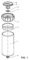
- Fig. 1 shows an example of a lubrication device 10 according to the invention that is adapted to be screwed to a machine part to be lubricated.
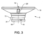
- Fig. 2a and 2b respectively show a top view and a cross-sectional view of a collar part 2 and Fig. 3 shows an insert 5 used in the device of Fig. 1 .
- the lubrication device may be designed for either grease or oil lubrication. For the grease version, it suffices to provide the nozzle region with a properly designed outlet opening, whereas the oil version requires that the outlet opening is provided with an oil valve.
- Fig. 1 shows an example of a lubrication device that is adapted to dispense grease.
- the lubrication device 10 comprises a container 1 in the form of a cylinder provided at a first end with a nozzle region 6 having an external thread.
- the device of this example further comprises a piston 3 that separates a grease reservoir from a gas pressure chamber above the piston.
- the piston 3 is pushed downwards towards the nozzle region when gas is generated, thereby supplying grease to the part to be lubricated.
- the grease is held in the container 1 within a collapsible bag, in which case the piston 3 is optional.
- the container 1 is covered by a collar 2 and a insert 5 received within the collar 2.
- the insert 5 is rotatable relative to the collar 2, and the collar is fixedly attached to an upper rim of the container 1. This may be done by using glue or, since both parts are made from plastic in the shown example, by spin welding. Other types of fixation means, such as a snap lock, would also be possible to use.
- the collar 2 comprises a first ledge 23 on which an upper rim 19 of the insert 5 rests, after it has been inserted into the collar.
- the insert 5 is adapted to house a gas generation cell, preferably a dry cell (not shown), which is held in engagement with the insert by means of e.g. longitudinal ribs on an inside cylindrical surface of the insert.
- a gas generation cell preferably a dry cell (not shown)
- the gas cell is further held within a metal clip, part of which clip makes electrical contact with a potentiometer plate 4 that is seated within the collar 2.
- the potentiometer plate 4 is held in a fixed position by e.g. ridges 11 in the collar and is suitably provided with protrusions that correspond to the ridges.
- the potentiometer plate is held in a fixed position and the insert 5 and gas cell are rotated in order to vary the resistance of the electric circuit formed between the gas cell and the potentiometer plate 4, thereby varying the current and amount of gas generated.
- a seal ring is provided between the insert 5 and the collar 2 in order to make the gas chamber gas-tight.
- the collar 2 comprises a second ledge 24 on which the seal ring sits and seals against an engaging surface of the rotatable insert 5.
- a top surface of the collar 2 may be provided with a face dial 8 with e.g. numbers that indicate the release rate of lubricant from the lubrication device, corresponding to the amount of gas generated.
- the face dial 8 has one zero position 7 in which the lubrication device is turned off. In this position, there is no electrical connection of the gas cell, which means that no gas is generated.
- the device further comprises a release position 9 of the collar relative to the rotatable insert 5, in which it is possible to remove the insert 5 from the collar in a relatively easy way. According to the invention, a force required to remove the insert from the collar is lower in the release position than in non-release positions of the device. This will be explained in greater detail below.
- the release position comprises a cut-out 17 in the top surface of the collar.
- the cut-out is adapted to receive e.g. a screw driver blade and is thus at least a few millimetres wide.
- the depth of the cut-out is such that it reaches below the first ledge 23 on which the upper rim 19 of the insert 5 sits, thereby enabling a tool to be inserted underneath the rim 19 so that the insert can be prized off.
- the insert 5 is suitably provided with an indicator 12 that shows the position of the rotatable insert relative to the face dial 8 on the collar 2.
- the insert 5 may further comprise a central slot 13 that is used to turn the insert to the desired position.
- the slot is adapted to receive a screwdriver, a coin or the like.
- the insert is further provided with a continuous groove 15 that extends around a base 18 of the insert.
- the groove 15 is provided with a contact surface 21 that is adapted to cooperate with catches 14 arranged in the collar 2.
- the contact surface 21 and the catches 14 cooperate as a snap lock such that when the insert is snapped into the collar, it cannot be removed without damaging the device.
- the contact surface 21 of the groove and the surfaces of the catches that bear on each other are both straight, i.e.
- the rotatable insert 5 will be held securely in place even when the pressure in the gas chamber rises above the working pressure.
- the working pressure is around 0.3 - 0.7 bar.
- the groove and catches are designed to withstand a pressure of up to 2.5 bar, while in non-release positions, the groove and catches can withstand a pressure of up to 5 bar. It is therefore important that the surfaces of the groove and the catches can withstand an excessive pressure.
- the insert 5 is further provided with a small notch 16 in the contact surface 21 of the groove 15.
- the surface of the notch may be slightly angled.
- the notch 16 will at the same time be positioned at a release edge 22 of one of the catches 14 in the shown example. If a suitable pry tool, a screw-driver or the like is inserted in the cut-out 17, the insert can be forced out of position relatively easily, since the base of the rotatable button will deform somewhat due to the force of the pry tool.
- the notch 16 is provided in the contact surface 21 at a position where the notch will be aligned with the release edge 22 when the rotatable insert is in the release position. In this way, the force from the pry tool will allow the rotatable insert to be released. If a user tries to remove the insert 5 when the insert is not in the release position, a straight part of the contact surface 21 will bear on the release edge. The rotatable insert will thus only release at a substantially higher pry force.
- the notch 16 may be positioned anywhere on the contact surface 21, but it is of advantage to position it in the region of the indicator 12, preferably within 90 degrees from the indicator position.
- the size of the notch 16 may also differ depending on the requirements.
- the width of the notch may, as in the shown example, be slightly narrower than the corresponding catch, or the width may be the same as the catch. When the notch has the same width as a catch, it is preferred to have one release catch that is narrower than the other catches. In this way, the notch will only correspond to the catch in the release position, and accidental release of the rotatable button is further prevented.
- the upper rim of the insert 5 may be provided with a recess 20.
- a screwdriver or similar pry tool may then be inserted into the cut-out 17 and into the recess in the rim. This will allow the pry tool to exert a higher torque on the insert.
- the cut-out 17 on the collar 2 need not extend below the rim 19 of the insert 5, meaning that it is only possible to prize off the insert 5 when the recess 20 is in alignment with the cut-out 17; i.e. in the release position 9.
- the contact surface 21 of the insert 5 and the catches 14 of the collar must be able to withstand this pressure.
- the force required for removing the insert must thus be higher than this pressure.
- the base 18 of the insert may be designed such that it breaks when it is removed.
- the notch may also constitute a weakening of the base that will cause at least part of the base to break off.
- at least one of the catches 14 on the collar 2 may be adapted to break off when the insert 5 is prized out.
- the different parts of the lubrication device may be disposed of separately. Some parts may be recycled and some parts may be taken to a refuse incinerator for destruction. In this way, a lubrication device is provided that is tamper-proof, i.e. that is guaranteed to meet the specifications of the manufacturer, and that can be recycled in an easy way.
Landscapes
- Engineering & Computer Science (AREA)
- General Engineering & Computer Science (AREA)
- Mechanical Engineering (AREA)
- Portable Nailing Machines And Staplers (AREA)
- Compressor (AREA)
- Connector Housings Or Holding Contact Members (AREA)
- Containers And Packaging Bodies Having A Special Means To Remove Contents (AREA)
- Closures For Containers (AREA)
Description
- The present invention relates to a device for gas pressure-driven lubrication of a lubrication point.
- In industry, there is a constant need to lubricate moving systems, such as moving axles, rotating bearings and other machine elements having surfaces that bear and glide on each other. In some cases, lubrication-free components may be used: This is however only possible for lower loads and slow moving speeds. For other systems, where high loads are imposed on the bearing surfaces and/or where the speed, either rotational or linear, is relatively high, there exists a need to lubricate the surfaces. The periodicity of the application of lubricant and the amount of lubrication applied may vary extensively. In some cases, a small amount of lubricant may be required every day and in other cases, lubrication may be performed every three months.
- Especially when the lubrication must be performed at short intervals, and also where the lubrication point is hard to reach, an automatic lubrication device is advantageous. There are known lubrication devices that comprise a pump of some kind, a lubricant reservoir such as a grease container and a control unit that dispenses a predefined amount of lubricant to the lubrication point at predetermined time intervals. Such a system is rather complicated and the size is often rather large.
- Another type of automatic lubrication device is a self-contained grease container which somewhat resembles a grease cartridge. Such a grease container comprises a gas generating cell and a compartment of grease which dispenses grease from the compartment to the lubrication point. The gas generation may be based on a dry cell that produces gas in an electrochemical way. The amount of generated gas is controlled by the current flowing from a gas generating electrode to a counter electrode. The generated gas will build up a pressure inside the container which in turn causes a piston to dispense grease from a lubricant opening.
- Such a lubrication device is known from
US 5,012,897 . In this lubrication device, two gas cells are connected to each other through a fixed resistor by an intermediate spring. By screwing the top part of the device into the container lid, the spring connects the two cells such that the electric circuit closes and gas starts to generate. The top part may be unscrewed somewhat in order to disconnect the electrical circuit, and by unscrewing the top part completely, new gas cells may be fitted. - One disadvantage of being able to replace the gas cell in an easy way is that the manufacturer of the lubrication device cannot guarantee a proper function of the lubrication device since it is possible to tamper with the gas cell. By replacing the gas cell, there is a possibility for the user to insert a used gas cell with a reduced capacity, which would lead to a reduced life of the lubrication device compared with what was expected. It is also possible to insert a different type of gas cell or to position the gas cell in a wrong way, which would also lead to a malfunction of the lubrication device. In those cases, the lubrication of the machine part may fail with a breakdown as result. Further, it is possible to damage parts of the gas generating device which will also lead to the lubrication device not functioning properly.
-
DE 102004 013594 describes a lubrication device in which the lid may be used to set the amount of dispensed lubricant. The lid of the container is provided with a rotatable part comprising a potentiometer element. The rotatable part is provided with protrusions that stop the rotatable part from being removed once it is in position. The lid is fixedly attached to the container. In this way, the container may not be refilled and the gas cell may not be removed or replaced. - In this lubrication device, the user has no possibility to tamper with the gas cell. There is however no possibility to dispose of the gas cell in a proper manner. The gas cell, and in this case also the battery cell, should be removed before the rest of the lubrication device is disposed of. This makes it difficult to recycle the parts of the lubrication device. There is thus room for improvements.
- An object of the invention is therefore to provide a lubrication device that is tamper-proof and that can be taken apart for recycling and separate disposal of component parts in a straightforward manner. A further object of the invention is to provide a lubrication device with a reduced number of parts.
- The solution to the problem according to the invention is described in the characterizing part of
claim 1. The other claims contain advantageous embodiments and further developments of the lubrication device. - In a lubrication device for gas pressure-driven lubrication of a lubrication point, the device comprising a lubricant container which has an outlet opening at a first end and is covered at a second end by a combination of a collar and an insert received within the collar in a mechanically interlocking fashion, and further comprising a gas generation means housed within the combination, the object of the invention is achieved in that the lubrication device is provided with a release position of the insert relative to the collar, in which a force required to remove the insert from the collar is lower than at non-release positions.
- The gas generation means is housed in one of the insert or the collar, and the mechanical interlock between these two components is therefore able to withstand at least the working pressure of the device. In the non-release positions, a removal force required to disengage the mechanical interlock may be at least five times greater than a maximum working force exerted on the mechanical interlock at a maximum working pressure of the device. To facilitate removal of the insert, to gain access to the gas generation means for separate disposal thereof, the removal force required when the device is in the release position may be less than four times the maximum working force. For safety reasons, the removal force in the release position is preferably at least two times greater than the maximum working force. Other values are possible, depending on the maximum working pressure, and the mechanical interlock between the insert and the collar is suitably designed such that the device can safely withstand excess pressures yet is relatively easy to take apart in the release position.
- According to the invention, the mechanical interlock is formed in that the collar comprises one or more catches and the insert comprises a groove with a contact surface which cooperates with the one or more catches. Suitably, the contact surface of the groove comprises a notch which, in the release position, is at least partially aligned with a catch of the collar. The mechanical interlock between the insert and the collar is therefore lower in the release position than at non-release positions of the insert relative to the collar, meaning that less force is required to remove the insert.
- In one embodiment, the collar comprises a cylindrical portion for receiving a corresponding portion of the insert, whereby the one or more catches are formed by protrusions on an inner surface of the cylindrical portion. The groove is provided on an outer surface of the corresponding portion of the insert, whereby the notch is provided in the contact surface of the groove. In some examples of a device according to the invention, the notch has the same width as a specific release catch that is narrower than other catches of the collar. In the release position, the narrow catch is aligned with the notch. Alternatively, the collar may comprise a single catch that is substantially wider than the notch, whereby a release edge of the catch is in alignment with the notch in the release position. In other examples, the collar comprises two or more catches that are slightly wider than the notch, whereby in the release position, the notch is aligned with a release edge of one of the catches.
- To further facilitate the removal of the insert from the collar, the collar suitably comprises a cut-out for receiving a pry tool. In a preferred embodiment, the release position is reached by aligning an indicator on the insert with the cut-out. The cut-out may extend below a ledge of the collar on which a rim of the insert rests, so that the pry tool may be inserted underneath the rim of the insert in order to prize off the insert. In an alternative embodiment, the cut-out does not extend below the ledge and the rim of the insert comprises an inwardly extending recess for receiving e.g. the blade of a screwdriver, such that the insert can only be prized off when the recess is aligned with the cut-out.
- In some examples of a lubrication device according to the invention, the gas generation means is housed within the insert. In other examples, the gas generation means is housed in the cylindrical portion of the collar that receives the insert, such that the insert serves as a cap. Further, the device may be executed with the collar being rotatable relative to the insert, but is preferably executed with the insert being rotatable relative to the collar. This latter execution is advantageous in that one end of the lubricant container can be covered by only two parts, one of which holds the gas generation means. As a result, the device need be provided with only one seal between the collar and the insert, thereby minimising the number of component parts of the device.
- Any electrochemical gas generation means which are suitable for a gas pressure-driven lubricator may be used in a device according to the invention; for example, an electrolytic cell and separate battery. In a preferred embodiment, the gas generation means is a dry cell such as disclosed in
US 5242565 . The advantage of a dry cell is that a separate battery is not required, which again allows the number of component parts to be minimized. - To enable control of the rate of gas generation, a device according to the invention may comprise a variable resistor. In one embodiment, the device comprises a potentiometer plate which is held fixed in the collar and which is in electrical contact with a dry cell, whereby the dry cell is held fixed within the insert and is rotatable with the insert in order to vary the resistance of the potentiometer. In an alternative embodiment, the cylindrical portion of the collar houses the gas generation means and the insert holds a variable resistor that is turned in order to control the gas generation rate.
- By these embodiments of the lubrication device according to the invention, a lubrication device is provided that is tamper-proof and that can be taken apart in a release position. In this way, the function of the lubrication device can be guaranteed during the life of the lubrication device, since the lubrication device is not adapted to be taken apart or to be serviced by a user, e.g. with the purpose of refilling the container and/or to replace the gas generating means. At the same time, it is possible to easily remove the part of the lubrication device, so as to gain access to the gas generation means, which requires separate disposal. Other advantages of the invention will become apparent from the following more detailed description and accompanying figures.
- The invention will be described in greater detail in the following, with reference to the embodiments that are shown in the attached drawings, in which
- Fig. 1
- shows a lubrication device according to the invention,
- Fig. 2a
- shows a top view of a collar of the device,
- Fig. 2b
- shows a cross-sectional view of the collar, and
- Fig. 3
- shows a detail of an insert of the lubrication device according to the invention.
- The embodiments of the invention with further developments described in the following are to be regarded only as examples and are in no way to limit the scope of the protection provided by the patent claims.
-
Fig. 1 shows an example of a lubrication device 10 according to the invention that is adapted to be screwed to a machine part to be lubricated.Fig. 2a and 2b respectively show a top view and a cross-sectional view of acollar part 2 andFig. 3 shows aninsert 5 used in the device ofFig. 1 . The lubrication device may be designed for either grease or oil lubrication. For the grease version, it suffices to provide the nozzle region with a properly designed outlet opening, whereas the oil version requires that the outlet opening is provided with an oil valve.Fig. 1 shows an example of a lubrication device that is adapted to dispense grease. - The lubrication device 10 comprises a
container 1 in the form of a cylinder provided at a first end with anozzle region 6 having an external thread. The device of this example further comprises apiston 3 that separates a grease reservoir from a gas pressure chamber above the piston. Thepiston 3 is pushed downwards towards the nozzle region when gas is generated, thereby supplying grease to the part to be lubricated. In some embodiments, the grease is held in thecontainer 1 within a collapsible bag, in which case thepiston 3 is optional. - At a second end of the container, the
container 1 is covered by acollar 2 and ainsert 5 received within thecollar 2. In this example, theinsert 5 is rotatable relative to thecollar 2, and the collar is fixedly attached to an upper rim of thecontainer 1. This may be done by using glue or, since both parts are made from plastic in the shown example, by spin welding. Other types of fixation means, such as a snap lock, would also be possible to use. Thecollar 2 comprises afirst ledge 23 on which anupper rim 19 of theinsert 5 rests, after it has been inserted into the collar. - In the device of
Fig. 1 , theinsert 5 is adapted to house a gas generation cell, preferably a dry cell (not shown), which is held in engagement with the insert by means of e.g. longitudinal ribs on an inside cylindrical surface of the insert. In order to control the amount of gas generated, the gas cell is further held within a metal clip, part of which clip makes electrical contact with apotentiometer plate 4 that is seated within thecollar 2. Thepotentiometer plate 4 is held in a fixed position by e.g.ridges 11 in the collar and is suitably provided with protrusions that correspond to the ridges. In this way, the potentiometer plate is held in a fixed position and theinsert 5 and gas cell are rotated in order to vary the resistance of the electric circuit formed between the gas cell and thepotentiometer plate 4, thereby varying the current and amount of gas generated. Further, a seal ring is provided between theinsert 5 and thecollar 2 in order to make the gas chamber gas-tight. Suitably, thecollar 2 comprises asecond ledge 24 on which the seal ring sits and seals against an engaging surface of therotatable insert 5. - As shown best in
Fig 2a , a top surface of thecollar 2 may be provided with aface dial 8 with e.g. numbers that indicate the release rate of lubricant from the lubrication device, corresponding to the amount of gas generated. Theface dial 8 has one zeroposition 7 in which the lubrication device is turned off. In this position, there is no electrical connection of the gas cell, which means that no gas is generated. The device further comprises arelease position 9 of the collar relative to therotatable insert 5, in which it is possible to remove theinsert 5 from the collar in a relatively easy way. According to the invention, a force required to remove the insert from the collar is lower in the release position than in non-release positions of the device. This will be explained in greater detail below. - The release position comprises a cut-out 17 in the top surface of the collar. The cut-out is adapted to receive e.g. a screw driver blade and is thus at least a few millimetres wide. In the depicted example, the depth of the cut-out is such that it reaches below the
first ledge 23 on which theupper rim 19 of theinsert 5 sits, thereby enabling a tool to be inserted underneath therim 19 so that the insert can be prized off. - The
insert 5 is suitably provided with anindicator 12 that shows the position of the rotatable insert relative to theface dial 8 on thecollar 2. Theinsert 5 may further comprise acentral slot 13 that is used to turn the insert to the desired position. The slot is adapted to receive a screwdriver, a coin or the like. The insert is further provided with acontinuous groove 15 that extends around abase 18 of the insert. Thegroove 15 is provided with acontact surface 21 that is adapted to cooperate withcatches 14 arranged in thecollar 2. Thecontact surface 21 and thecatches 14 cooperate as a snap lock such that when the insert is snapped into the collar, it cannot be removed without damaging the device. Thecontact surface 21 of the groove and the surfaces of the catches that bear on each other are both straight, i.e. perpendicular to the central axis of the lubrication device. In this way, therotatable insert 5 will be held securely in place even when the pressure in the gas chamber rises above the working pressure. In one example of a 125 ml lubrication device, the working pressure is around 0.3 - 0.7 bar. In the release position, the groove and catches are designed to withstand a pressure of up to 2.5 bar, while in non-release positions, the groove and catches can withstand a pressure of up to 5 bar. It is therefore important that the surfaces of the groove and the catches can withstand an excessive pressure. - In order to facilitate the removing of the rotatable insert from the collar for separate disposal of the gas cell, the
insert 5 is further provided with asmall notch 16 in thecontact surface 21 of thegroove 15. The surface of the notch may be slightly angled. When the rotatable insert is turned to therelease position 9 with theindicator 12 facing the cut-out 17 in thecollar 2, thenotch 16 will at the same time be positioned at arelease edge 22 of one of thecatches 14 in the shown example. If a suitable pry tool, a screw-driver or the like is inserted in the cut-out 17, the insert can be forced out of position relatively easily, since the base of the rotatable button will deform somewhat due to the force of the pry tool. This will allow theangled notch 16 to slide off the release edge of the catch instead of being caught by it. Thenotch 16 is provided in thecontact surface 21 at a position where the notch will be aligned with therelease edge 22 when the rotatable insert is in the release position. In this way, the force from the pry tool will allow the rotatable insert to be released. If a user tries to remove theinsert 5 when the insert is not in the release position, a straight part of thecontact surface 21 will bear on the release edge. The rotatable insert will thus only release at a substantially higher pry force. - The
notch 16 may be positioned anywhere on thecontact surface 21, but it is of advantage to position it in the region of theindicator 12, preferably within 90 degrees from the indicator position. The size of thenotch 16 may also differ depending on the requirements. The width of the notch may, as in the shown example, be slightly narrower than the corresponding catch, or the width may be the same as the catch. When the notch has the same width as a catch, it is preferred to have one release catch that is narrower than the other catches. In this way, the notch will only correspond to the catch in the release position, and accidental release of the rotatable button is further prevented. - In order to further facilitate the release of the rotatable insert, and also to provide a release protection in which the pry tool can only be inserted into the cut-out 17 when the rotatable insert is in the release position, the upper rim of the
insert 5 may be provided with arecess 20. A screwdriver or similar pry tool may then be inserted into the cut-out 17 and into the recess in the rim. This will allow the pry tool to exert a higher torque on the insert. When therotatable insert 5 comprises such a recess, the cut-out 17 on thecollar 2 need not extend below therim 19 of theinsert 5, meaning that it is only possible to prize off theinsert 5 when therecess 20 is in alignment with the cut-out 17; i.e. in therelease position 9. - Since the design pressure of the container is relatively high, and since the rotatable insert defines part of the pressure chamber of the lubrication device, the
contact surface 21 of theinsert 5 and thecatches 14 of the collar must be able to withstand this pressure. The force required for removing the insert must thus be higher than this pressure. As the lubrication device is not intended to be used again, i.e. it should not be possible to replace the rotatable insert, thebase 18 of the insert may be designed such that it breaks when it is removed. In this case, the notch may also constitute a weakening of the base that will cause at least part of the base to break off. Alternatively, at least one of thecatches 14 on thecollar 2 may be adapted to break off when theinsert 5 is prized out. - When the rotatable insert is removed, the different parts of the lubrication device may be disposed of separately. Some parts may be recycled and some parts may be taken to a refuse incinerator for destruction. In this way, a lubrication device is provided that is tamper-proof, i.e. that is guaranteed to meet the specifications of the manufacturer, and that can be recycled in an easy way.
- The invention is not to be regarded as being limited to the embodiments described above, a number of additional variants and modifications being possible within the scope of the subsequent patent claims.
-
- 1:
- Container
- 2:
- Collar
- 3:
- Piston
- 4:
- Potentiometer plate
- 5:
- Rotatable insert
- 6:
- Nozzle region of container
- 7:
- Zero position
- 8:
- Dial on top surface of collar
- 9:
- Release position
- 10:
- Lubrication device
- 11:
- Ridge
- 12:
- Indicator on rotatable insert
- 13:
- Slot
- 14:
- Catch within the collar
- 15:
- Groove in rotatable insert
- 16:
- Notch in the groove
- 17:
- Cut-out in top surface of collar
- 18:
- Base of rotatable insert
- 19:
- Rim of rotatable insert
- 20:
- Recess
- 21:
- Contact surface of groove
- 22:
- Release edge of catch
- 23:
- First ledge on collar
- 24:
- Second ledge on collar
Claims (15)
- Lubrication device (10) for gas pressure-driven lubrication of a lubrication point, comprising:a lubricant container (1) provided at a first end with an outlet opening (6) and covered at a second end by a combination of a collar (2) and an insert (5) received within the collar (2), whereby the collar and the insert are relatively rotatable; anda gas generation means housed within said combination;characterized in that,the insert (5) is provided with a groove (15) having a contact surface (21) forming a mechanical interlock with one or more catches (14) of the collar (2) when the insert (5) is inserted into collar (2), andthe lubrication device (10) is provided with a release position (9) of the insert (5) relative to the collar (2), in which a force required to disengage the mechanical interlock is lower than at non-release positions, so that the insert can be removed to gain access to the gas generation means for separate disposal thereof.
- Device according to claim 1, wherein
in the release position (9), the force required to disengage the mechanical interlock is between two and four times greater than a force exerted on the mechanical interlock at a maximum working pressure of the device; and
in non-release positions, the force required to disengage the mechanical interlock is at least five times greater than a force exerted on the mechanical interlock at the maximum working pressure of the device. - Device according to claim 1 or 2, wherein the contact surface (21) of the groove (15) comprises a notch (16) which, in the release position (9), is aligned with a release edge (22) of a catch (14) of the collar.
- Device according to claim 3, wherein the notch (16) is angled such that the release edge (22) can slide against the notch during the removal of the insert (5).
- Device according to claim 1 or 2, wherein the contact surface (21) of the groove (15) comprises a notch (16) which, in the release position (9), is aligned with a catch (14) of the collar.
- Device according to claim 5, wherein the collar (2) comprises two or more catches (14), one catch being narrower than the other catches.
- Device according to claim 6, wherein the notch (16) has the same width as the narrow catch, which narrow catch is in alignment with the notch (16) when the device is in the release position (9).
- Device according to any preceding claim, wherein the release position (9) is reached by aligning an indicator (12) on the insert (5) with a cut-out (17) of the collar (2), the cut-out (17) being adapted to receive a removal tool for prizing off the insert (5).
- Device according to claim 1 to 8, wherein the collar (2) comprises an upper ledge (23) on which an upper rim (19) of the insert (5) rests, and the cut-out (17) of the collar (2) has a depth which extends below the upper ledge.
- Device according to claim 8 or 9, wherein the depth of the cut-out (17) is level with the upper ledge (23) and the insert (5) is provided with a recess (20) in the upper rim, which recess is in alignment with the cut-out (17) in the release position (9) of the device.
- Device according to any preceding claim, wherein the groove (15) of the insert (5) and/or a catch (14) of the collar (2) comprises a weakening that is adapted to break off when the insert (5) is removed from the collar.
- Device according to any preceding claim, further comprising a potentiometer (4) for varying a current supplied to the gas generation means.
- Device according to any preceding claim, wherein the insert (5) is rotatable relative to the collar (2).
- Device according to claim 13, wherein the gas generation means is housed within the insert and is rotatable therewith.
- Device according to any of claims 12 to claim 14, wherein the potentiometer (4) is fixedly positioned in the collar (2).
Applications Claiming Priority (1)
| Application Number | Priority Date | Filing Date | Title |
|---|---|---|---|
| PCT/EP2010/003129 WO2011144227A1 (en) | 2010-05-21 | 2010-05-21 | Single point lubricator |
Publications (2)
| Publication Number | Publication Date |
|---|---|
| EP2572136A1 EP2572136A1 (en) | 2013-03-27 |
| EP2572136B1 true EP2572136B1 (en) | 2014-02-26 |
Family
ID=43637210
Family Applications (1)
| Application Number | Title | Priority Date | Filing Date |
|---|---|---|---|
| EP10722942.9A Active EP2572136B1 (en) | 2010-05-21 | 2010-05-21 | Single point lubricator |
Country Status (5)
| Country | Link |
|---|---|
| US (1) | US9273826B2 (en) |
| EP (1) | EP2572136B1 (en) |
| CN (1) | CN102906483B (en) |
| BR (1) | BR112012027646B1 (en) |
| WO (1) | WO2011144227A1 (en) |
Cited By (1)
| Publication number | Priority date | Publication date | Assignee | Title |
|---|---|---|---|---|
| US9400084B2 (en) | 2011-07-20 | 2016-07-26 | Aktiebolaget Skf | Lubrication device and protective cover for a lubrication device |
Families Citing this family (1)
| Publication number | Priority date | Publication date | Assignee | Title |
|---|---|---|---|---|
| CN104358994A (en) * | 2014-09-26 | 2015-02-18 | 安徽沃特普尔节能科技有限公司 | Automatic grease supplementing machine |
Family Cites Families (21)
| Publication number | Priority date | Publication date | Assignee | Title |
|---|---|---|---|---|
| US4023648A (en) * | 1974-05-09 | 1977-05-17 | Anton Orlitzky | Lubricant applicators |
| NL8501839A (en) * | 1985-06-26 | 1987-01-16 | Skf Ind Trading & Dev | DEVICE FOR DELIVERING A LUBRICANT. |
| US4671386A (en) * | 1985-10-01 | 1987-06-09 | Anton Orlitzky | Lubricating apparatus |
| DE3644207A1 (en) * | 1986-12-23 | 1988-07-07 | Satzinger Gebhard Gmbh Co | DEVICE FOR CONTINUOUSLY DELIVERING LIQUID OR VISCOSE MEDIA, ESPECIALLY LUBRICANTS |
| US5242565A (en) | 1989-07-10 | 1993-09-07 | August Winsel | Device for electrochemical generation of gases for the transportation of fluids and similar mediums |
| DE4209776A1 (en) * | 1992-03-26 | 1993-09-30 | Satzinger Gmbh & Co | Lubricant dispenser for gas-controlled delivery of a lubricant to a machine |
| KR0110998Y1 (en) * | 1992-12-01 | 1997-12-22 | Hankuk Lubrication Technology | Device for supplying lubrication oil |
| DK0629169T3 (en) * | 1992-12-11 | 1997-08-25 | Wiva Bv | Waste bin cover |
| EP0644369A1 (en) | 1993-09-21 | 1995-03-22 | Satzinger GmbH & Co. | Lubricant dispenser for gas controlled dispensing of lubricant to a machine |
| DE4331947C1 (en) * | 1993-09-21 | 1994-11-17 | Satzinger Gmbh & Co | Lubricant dispenser for the gas-controlled delivery of a lubricant to a machine |
| DE4446463C1 (en) * | 1994-12-28 | 1996-02-08 | Satzinger Gmbh & Co | Dispensing system for lubricant |
| CA2488809A1 (en) * | 2002-06-12 | 2003-12-24 | Lubriquip, Inc. | Automatic lubrication system |
| CN100412437C (en) * | 2002-10-18 | 2008-08-20 | 程虎 | Pneumatic self-suction type high-pressure oil ejector |
| WO2005003619A2 (en) * | 2003-07-07 | 2005-01-13 | Natasa Enterprises Ltd. | Reusable fluid dispenser |
| DE102004013594B4 (en) | 2004-03-19 | 2007-02-01 | Perma-Tec Gmbh & Co. Kg | lubricant dispenser |
| US7398891B2 (en) * | 2004-05-12 | 2008-07-15 | Shih-Sheng Yang | Cover structure for water bag inlet |
| DE102005004456B4 (en) * | 2005-02-01 | 2010-07-15 | Perma-Tec Gmbh & Co. Kg | lubricant dispenser |
| CN101122361A (en) * | 2006-08-10 | 2008-02-13 | 刘馀明 | Air pressure controlled grease injection device |
| DE102007010518B4 (en) * | 2007-03-05 | 2009-03-19 | Perma-Tec Gmbh & Co. Kg | Method for dispensing lubricants and gas generating element for carrying out the method |
| DE102007037422A1 (en) * | 2007-08-08 | 2009-02-19 | Perma-Tec Gmbh & Co. Kg | lubricant dispenser |
| DE102009022707B4 (en) * | 2009-03-05 | 2014-03-27 | Perma-Tec Gmbh & Co. Kg | lubricant dispenser |
-
2010
- 2010-05-21 WO PCT/EP2010/003129 patent/WO2011144227A1/en not_active Ceased
- 2010-05-21 EP EP10722942.9A patent/EP2572136B1/en active Active
- 2010-05-21 CN CN201080066931.1A patent/CN102906483B/en active Active
- 2010-05-21 US US13/698,877 patent/US9273826B2/en active Active
- 2010-05-21 BR BR112012027646-8A patent/BR112012027646B1/en active IP Right Grant
Cited By (1)
| Publication number | Priority date | Publication date | Assignee | Title |
|---|---|---|---|---|
| US9400084B2 (en) | 2011-07-20 | 2016-07-26 | Aktiebolaget Skf | Lubrication device and protective cover for a lubrication device |
Also Published As
| Publication number | Publication date |
|---|---|
| WO2011144227A1 (en) | 2011-11-24 |
| EP2572136A1 (en) | 2013-03-27 |
| US20140144727A1 (en) | 2014-05-29 |
| BR112012027646B1 (en) | 2020-10-13 |
| BR112012027646A2 (en) | 2016-08-16 |
| CN102906483B (en) | 2016-04-06 |
| US9273826B2 (en) | 2016-03-01 |
| CN102906483A (en) | 2013-01-30 |
Similar Documents
| Publication | Publication Date | Title |
|---|---|---|
| US5386883A (en) | Automatic lubricant dispenser | |
| EP0182519B1 (en) | Closure device for containers | |
| US8944292B2 (en) | Dispenser of fluid material | |
| EP0598867A1 (en) | Device for the intentional and controllable distribution of a liquid or visquous material. | |
| CN103998849B (en) | Lubricant dispenser | |
| KR100371107B1 (en) | Automatic lubricant transfer device | |
| US20140144727A1 (en) | Single Point Lubricator | |
| US20230406582A1 (en) | Tamper-evident closure | |
| US20020070236A1 (en) | Tamper evident valve outlet cap | |
| CA2832442A1 (en) | Cap with additive chamber and associated packaging unit | |
| JP2010027621A (en) | Electrochemical device | |
| JP5712115B2 (en) | Refill container | |
| EP2399059B1 (en) | Fluid holder and electromechanical lubricator employing same | |
| JP4818867B2 (en) | Double container | |
| EP3699411A2 (en) | Safety cap for a liquid reservoir for a motor vehicle | |
| KR20030000158A (en) | Engine oil cap | |
| US1240906A (en) | Friction-locked grease-cup. | |
| EP0603141B1 (en) | Lubricant container | |
| US332623A (en) | Lubricator | |
| US817529A (en) | Lubricator. | |
| KR100254562B1 (en) | Oil pan drain plug | |
| US1168478A (en) | Grease-cup. | |
| KR960006420B1 (en) | Auto lubrication device | |
| WO1988009901A1 (en) | Device for continuously supplying liquid or viscous media, in particular lubricants | |
| US1336135A (en) | Grease-cup |
Legal Events
| Date | Code | Title | Description |
|---|---|---|---|
| PUAI | Public reference made under article 153(3) epc to a published international application that has entered the european phase |
Free format text: ORIGINAL CODE: 0009012 |
|
| 17P | Request for examination filed |
Effective date: 20121114 |
|
| AK | Designated contracting states |
Kind code of ref document: A1 Designated state(s): AL AT BE BG CH CY CZ DE DK EE ES FI FR GB GR HR HU IE IS IT LI LT LU LV MC MK MT NL NO PL PT RO SE SI SK SM TR |
|
| DAX | Request for extension of the european patent (deleted) | ||
| GRAP | Despatch of communication of intention to grant a patent |
Free format text: ORIGINAL CODE: EPIDOSNIGR1 |
|
| INTG | Intention to grant announced |
Effective date: 20131108 |
|
| GRAS | Grant fee paid |
Free format text: ORIGINAL CODE: EPIDOSNIGR3 |
|
| GRAA | (expected) grant |
Free format text: ORIGINAL CODE: 0009210 |
|
| AK | Designated contracting states |
Kind code of ref document: B1 Designated state(s): AL AT BE BG CH CY CZ DE DK EE ES FI FR GB GR HR HU IE IS IT LI LT LU LV MC MK MT NL NO PL PT RO SE SI SK SM TR |
|
| REG | Reference to a national code |
Ref country code: GB Ref legal event code: FG4D |
|
| REG | Reference to a national code |
Ref country code: CH Ref legal event code: EP |
|
| REG | Reference to a national code |
Ref country code: AT Ref legal event code: REF Ref document number: 653825 Country of ref document: AT Kind code of ref document: T Effective date: 20140315 |
|
| REG | Reference to a national code |
Ref country code: IE Ref legal event code: FG4D |
|
| REG | Reference to a national code |
Ref country code: DE Ref legal event code: R096 Ref document number: 602010013753 Country of ref document: DE Effective date: 20140410 |
|
| REG | Reference to a national code |
Ref country code: NL Ref legal event code: VDEP Effective date: 20140226 |
|
| REG | Reference to a national code |
Ref country code: AT Ref legal event code: MK05 Ref document number: 653825 Country of ref document: AT Kind code of ref document: T Effective date: 20140226 |
|
| REG | Reference to a national code |
Ref country code: LT Ref legal event code: MG4D |
|
| PG25 | Lapsed in a contracting state [announced via postgrant information from national office to epo] |
Ref country code: NO Free format text: LAPSE BECAUSE OF FAILURE TO SUBMIT A TRANSLATION OF THE DESCRIPTION OR TO PAY THE FEE WITHIN THE PRESCRIBED TIME-LIMIT Effective date: 20140526 Ref country code: LT Free format text: LAPSE BECAUSE OF FAILURE TO SUBMIT A TRANSLATION OF THE DESCRIPTION OR TO PAY THE FEE WITHIN THE PRESCRIBED TIME-LIMIT Effective date: 20140226 Ref country code: IS Free format text: LAPSE BECAUSE OF FAILURE TO SUBMIT A TRANSLATION OF THE DESCRIPTION OR TO PAY THE FEE WITHIN THE PRESCRIBED TIME-LIMIT Effective date: 20140626 |
|
| PG25 | Lapsed in a contracting state [announced via postgrant information from national office to epo] |
Ref country code: FI Free format text: LAPSE BECAUSE OF FAILURE TO SUBMIT A TRANSLATION OF THE DESCRIPTION OR TO PAY THE FEE WITHIN THE PRESCRIBED TIME-LIMIT Effective date: 20140226 Ref country code: AT Free format text: LAPSE BECAUSE OF FAILURE TO SUBMIT A TRANSLATION OF THE DESCRIPTION OR TO PAY THE FEE WITHIN THE PRESCRIBED TIME-LIMIT Effective date: 20140226 Ref country code: NL Free format text: LAPSE BECAUSE OF FAILURE TO SUBMIT A TRANSLATION OF THE DESCRIPTION OR TO PAY THE FEE WITHIN THE PRESCRIBED TIME-LIMIT Effective date: 20140226 Ref country code: SE Free format text: LAPSE BECAUSE OF FAILURE TO SUBMIT A TRANSLATION OF THE DESCRIPTION OR TO PAY THE FEE WITHIN THE PRESCRIBED TIME-LIMIT Effective date: 20140226 Ref country code: PT Free format text: LAPSE BECAUSE OF FAILURE TO SUBMIT A TRANSLATION OF THE DESCRIPTION OR TO PAY THE FEE WITHIN THE PRESCRIBED TIME-LIMIT Effective date: 20140626 Ref country code: CY Free format text: LAPSE BECAUSE OF FAILURE TO SUBMIT A TRANSLATION OF THE DESCRIPTION OR TO PAY THE FEE WITHIN THE PRESCRIBED TIME-LIMIT Effective date: 20140226 |
|
| PG25 | Lapsed in a contracting state [announced via postgrant information from national office to epo] |
Ref country code: HR Free format text: LAPSE BECAUSE OF FAILURE TO SUBMIT A TRANSLATION OF THE DESCRIPTION OR TO PAY THE FEE WITHIN THE PRESCRIBED TIME-LIMIT Effective date: 20140226 Ref country code: LV Free format text: LAPSE BECAUSE OF FAILURE TO SUBMIT A TRANSLATION OF THE DESCRIPTION OR TO PAY THE FEE WITHIN THE PRESCRIBED TIME-LIMIT Effective date: 20140226 Ref country code: BE Free format text: LAPSE BECAUSE OF FAILURE TO SUBMIT A TRANSLATION OF THE DESCRIPTION OR TO PAY THE FEE WITHIN THE PRESCRIBED TIME-LIMIT Effective date: 20140226 |
|
| PG25 | Lapsed in a contracting state [announced via postgrant information from national office to epo] |
Ref country code: DK Free format text: LAPSE BECAUSE OF FAILURE TO SUBMIT A TRANSLATION OF THE DESCRIPTION OR TO PAY THE FEE WITHIN THE PRESCRIBED TIME-LIMIT Effective date: 20140226 Ref country code: CZ Free format text: LAPSE BECAUSE OF FAILURE TO SUBMIT A TRANSLATION OF THE DESCRIPTION OR TO PAY THE FEE WITHIN THE PRESCRIBED TIME-LIMIT Effective date: 20140226 Ref country code: RO Free format text: LAPSE BECAUSE OF FAILURE TO SUBMIT A TRANSLATION OF THE DESCRIPTION OR TO PAY THE FEE WITHIN THE PRESCRIBED TIME-LIMIT Effective date: 20140226 Ref country code: EE Free format text: LAPSE BECAUSE OF FAILURE TO SUBMIT A TRANSLATION OF THE DESCRIPTION OR TO PAY THE FEE WITHIN THE PRESCRIBED TIME-LIMIT Effective date: 20140226 |
|
| REG | Reference to a national code |
Ref country code: DE Ref legal event code: R097 Ref document number: 602010013753 Country of ref document: DE |
|
| PG25 | Lapsed in a contracting state [announced via postgrant information from national office to epo] |
Ref country code: PL Free format text: LAPSE BECAUSE OF FAILURE TO SUBMIT A TRANSLATION OF THE DESCRIPTION OR TO PAY THE FEE WITHIN THE PRESCRIBED TIME-LIMIT Effective date: 20140226 Ref country code: SK Free format text: LAPSE BECAUSE OF FAILURE TO SUBMIT A TRANSLATION OF THE DESCRIPTION OR TO PAY THE FEE WITHIN THE PRESCRIBED TIME-LIMIT Effective date: 20140226 Ref country code: ES Free format text: LAPSE BECAUSE OF FAILURE TO SUBMIT A TRANSLATION OF THE DESCRIPTION OR TO PAY THE FEE WITHIN THE PRESCRIBED TIME-LIMIT Effective date: 20140226 |
|
| PG25 | Lapsed in a contracting state [announced via postgrant information from national office to epo] |
Ref country code: LU Free format text: LAPSE BECAUSE OF FAILURE TO SUBMIT A TRANSLATION OF THE DESCRIPTION OR TO PAY THE FEE WITHIN THE PRESCRIBED TIME-LIMIT Effective date: 20140521 |
|
| REG | Reference to a national code |
Ref country code: CH Ref legal event code: PL |
|
| PLBE | No opposition filed within time limit |
Free format text: ORIGINAL CODE: 0009261 |
|
| STAA | Information on the status of an ep patent application or granted ep patent |
Free format text: STATUS: NO OPPOSITION FILED WITHIN TIME LIMIT |
|
| PG25 | Lapsed in a contracting state [announced via postgrant information from national office to epo] |
Ref country code: CH Free format text: LAPSE BECAUSE OF NON-PAYMENT OF DUE FEES Effective date: 20140531 Ref country code: LI Free format text: LAPSE BECAUSE OF NON-PAYMENT OF DUE FEES Effective date: 20140531 Ref country code: MC Free format text: LAPSE BECAUSE OF FAILURE TO SUBMIT A TRANSLATION OF THE DESCRIPTION OR TO PAY THE FEE WITHIN THE PRESCRIBED TIME-LIMIT Effective date: 20140226 |
|
| 26N | No opposition filed |
Effective date: 20141127 |
|
| REG | Reference to a national code |
Ref country code: IE Ref legal event code: MM4A |
|
| REG | Reference to a national code |
Ref country code: DE Ref legal event code: R097 Ref document number: 602010013753 Country of ref document: DE Effective date: 20141127 |
|
| PG25 | Lapsed in a contracting state [announced via postgrant information from national office to epo] |
Ref country code: IT Free format text: LAPSE BECAUSE OF FAILURE TO SUBMIT A TRANSLATION OF THE DESCRIPTION OR TO PAY THE FEE WITHIN THE PRESCRIBED TIME-LIMIT Effective date: 20140226 |
|
| PG25 | Lapsed in a contracting state [announced via postgrant information from national office to epo] |
Ref country code: IE Free format text: LAPSE BECAUSE OF NON-PAYMENT OF DUE FEES Effective date: 20140521 |
|
| PG25 | Lapsed in a contracting state [announced via postgrant information from national office to epo] |
Ref country code: SI Free format text: LAPSE BECAUSE OF FAILURE TO SUBMIT A TRANSLATION OF THE DESCRIPTION OR TO PAY THE FEE WITHIN THE PRESCRIBED TIME-LIMIT Effective date: 20140226 |
|
| PG25 | Lapsed in a contracting state [announced via postgrant information from national office to epo] |
Ref country code: MT Free format text: LAPSE BECAUSE OF FAILURE TO SUBMIT A TRANSLATION OF THE DESCRIPTION OR TO PAY THE FEE WITHIN THE PRESCRIBED TIME-LIMIT Effective date: 20140226 |
|
| PG25 | Lapsed in a contracting state [announced via postgrant information from national office to epo] |
Ref country code: SM Free format text: LAPSE BECAUSE OF FAILURE TO SUBMIT A TRANSLATION OF THE DESCRIPTION OR TO PAY THE FEE WITHIN THE PRESCRIBED TIME-LIMIT Effective date: 20140226 |
|
| REG | Reference to a national code |
Ref country code: FR Ref legal event code: PLFP Year of fee payment: 7 |
|
| PG25 | Lapsed in a contracting state [announced via postgrant information from national office to epo] |
Ref country code: BG Free format text: LAPSE BECAUSE OF FAILURE TO SUBMIT A TRANSLATION OF THE DESCRIPTION OR TO PAY THE FEE WITHIN THE PRESCRIBED TIME-LIMIT Effective date: 20140226 Ref country code: GR Free format text: LAPSE BECAUSE OF FAILURE TO SUBMIT A TRANSLATION OF THE DESCRIPTION OR TO PAY THE FEE WITHIN THE PRESCRIBED TIME-LIMIT Effective date: 20140527 |
|
| PG25 | Lapsed in a contracting state [announced via postgrant information from national office to epo] |
Ref country code: TR Free format text: LAPSE BECAUSE OF FAILURE TO SUBMIT A TRANSLATION OF THE DESCRIPTION OR TO PAY THE FEE WITHIN THE PRESCRIBED TIME-LIMIT Effective date: 20140226 Ref country code: HU Free format text: LAPSE BECAUSE OF FAILURE TO SUBMIT A TRANSLATION OF THE DESCRIPTION OR TO PAY THE FEE WITHIN THE PRESCRIBED TIME-LIMIT; INVALID AB INITIO Effective date: 20100521 |
|
| PGFP | Annual fee paid to national office [announced via postgrant information from national office to epo] |
Ref country code: GB Payment date: 20160531 Year of fee payment: 7 |
|
| REG | Reference to a national code |
Ref country code: FR Ref legal event code: PLFP Year of fee payment: 8 |
|
| GBPC | Gb: european patent ceased through non-payment of renewal fee |
Effective date: 20170521 |
|
| PG25 | Lapsed in a contracting state [announced via postgrant information from national office to epo] |
Ref country code: GB Free format text: LAPSE BECAUSE OF NON-PAYMENT OF DUE FEES Effective date: 20170521 |
|
| REG | Reference to a national code |
Ref country code: FR Ref legal event code: PLFP Year of fee payment: 9 |
|
| PG25 | Lapsed in a contracting state [announced via postgrant information from national office to epo] |
Ref country code: MK Free format text: LAPSE BECAUSE OF FAILURE TO SUBMIT A TRANSLATION OF THE DESCRIPTION OR TO PAY THE FEE WITHIN THE PRESCRIBED TIME-LIMIT Effective date: 20140226 |
|
| PG25 | Lapsed in a contracting state [announced via postgrant information from national office to epo] |
Ref country code: AL Free format text: LAPSE BECAUSE OF FAILURE TO SUBMIT A TRANSLATION OF THE DESCRIPTION OR TO PAY THE FEE WITHIN THE PRESCRIBED TIME-LIMIT Effective date: 20140226 |
|
| P01 | Opt-out of the competence of the unified patent court (upc) registered |
Effective date: 20230627 |
|
| PGFP | Annual fee paid to national office [announced via postgrant information from national office to epo] |
Ref country code: DE Payment date: 20250528 Year of fee payment: 16 |
|
| PGFP | Annual fee paid to national office [announced via postgrant information from national office to epo] |
Ref country code: FR Payment date: 20250526 Year of fee payment: 16 |