EP2571118A1 - Spark plug - Google Patents
Spark plug Download PDFInfo
- Publication number
- EP2571118A1 EP2571118A1 EP11780365A EP11780365A EP2571118A1 EP 2571118 A1 EP2571118 A1 EP 2571118A1 EP 11780365 A EP11780365 A EP 11780365A EP 11780365 A EP11780365 A EP 11780365A EP 2571118 A1 EP2571118 A1 EP 2571118A1
- Authority
- EP
- European Patent Office
- Prior art keywords
- ground electrode
- metal shell
- spark plug
- rare earth
- welding
- Prior art date
- Legal status (The legal status is an assumption and is not a legal conclusion. Google has not performed a legal analysis and makes no representation as to the accuracy of the status listed.)
- Granted
Links
Images


Classifications
-
- H—ELECTRICITY
- H01—ELECTRIC ELEMENTS
- H01T—SPARK GAPS; OVERVOLTAGE ARRESTERS USING SPARK GAPS; SPARKING PLUGS; CORONA DEVICES; GENERATING IONS TO BE INTRODUCED INTO NON-ENCLOSED GASES
- H01T13/00—Sparking plugs
- H01T13/20—Sparking plugs characterised by features of the electrodes or insulation
- H01T13/32—Sparking plugs characterised by features of the electrodes or insulation characterised by features of the earthed electrode
-
- H—ELECTRICITY
- H01—ELECTRIC ELEMENTS
- H01T—SPARK GAPS; OVERVOLTAGE ARRESTERS USING SPARK GAPS; SPARKING PLUGS; CORONA DEVICES; GENERATING IONS TO BE INTRODUCED INTO NON-ENCLOSED GASES
- H01T13/00—Sparking plugs
- H01T13/20—Sparking plugs characterised by features of the electrodes or insulation
- H01T13/39—Selection of materials for electrodes
-
- F—MECHANICAL ENGINEERING; LIGHTING; HEATING; WEAPONS; BLASTING
- F02—COMBUSTION ENGINES; HOT-GAS OR COMBUSTION-PRODUCT ENGINE PLANTS
- F02P—IGNITION, OTHER THAN COMPRESSION IGNITION, FOR INTERNAL-COMBUSTION ENGINES; TESTING OF IGNITION TIMING IN COMPRESSION-IGNITION ENGINES
- F02P13/00—Sparking plugs structurally combined with other parts of internal-combustion engines
Definitions
- the present invention relates to a spark plug mounted to an internal combustion engine.
- the spark plugs have high ignition performance in order to cope with the strong demand for low emissions from recent internal combustion engines.
- the spark plug has a ground electrode of as large dimensions as possible welded to a metal shell even when the metal shell is reduced in diameter.
- the fused joint between the metal shell and the ground electrode decreases in size as the thickness of the ground electrode increases with increasing dimensions and becomes close to the thickness of the metal shell (see Patent Document 1). This leads to a deterioration in the joint strength between the metal shell and the ground electrode.
- the present invention has been made to solve at least part of the above problems and can be embodied in the following aspects or application examples.
- a spark plug comprising: a center electrode extending in an axial direction of the spark plug; a ground electrode formed of a metal material containing 95 mass% or more of nickel; and a substantially cylindrical metal shell having a front end face to which one end of the ground electrode is welded, wherein an embedment amount BD, an original width EW1 and a deformation width EW2 satisfy the conditions: 0.15 mm ⁇ BD ⁇ 0.40 mm; and (EW2-EW1)/EW1 ⁇ 0.1 where the embedment amount BD is a depth from the front end face of the metal shell to a portion of the ground electrode embedded most deeply in the metal shell by the welding of the ground electrode and the metal shell; the original width EW1 is a width of a portion of the ground electrode located closest to a portion of the ground electrode deformed by the welding; and the deformation width EW2 is a width of the portion of the ground electrode deformed by the welding at the front end face of the metal shell.
- the ground electrode has an increased thermal conductivity due to its very high nickel content of 95 mass% or more and thus can be welded to the metal shell in such a manner as to embed the portion of the ground electrode in the metal shell. Even when the spark plug is reduced in diameter, it is possible to secure the joint strength between the ground electrode and the metal shell by setting the depth of embedment (embedment amount BD) and the original width EW1 and deformation width EW2 of the ground electrode so as to satisfy the above conditions (0.15 mm ⁇ BD ⁇ 0.40 mm and (EW2-EW1)/EW1 ⁇ 0.1).
- the spark plug according to Application Example 1 or 2 wherein the spark plug has a removed surface region defined by removing, in the axial direction, at least a portion of a protruded part that has been formed in a thickness direction of the ground electrode by the welding of the ground electrode and the metal shell; and wherein a removed surface area CS and a ground electrode cross-sectional area ES satisfy the condition: CS/ES ⁇ 1.2 where the removed surface area CS is an area of the removed surface region; and the ground electrode cross-sectional area ES is an area of a cross section taken perpendicular to the axial direction through the portion of the ground electrode located closest to the portion of the ground electrode deformed by the welding. It is possible to secure the joint strength between the ground electrode and the metal shell more assuredly by setting the removed surface area CS and the ground electrode cross-sectional area ES so as to satisfy the above condition.
- the ground electrode contains a rare earth element; wherein the spark plug comprises, at the portion of the ground electrode embedded most deeply in the metal shell, a fused layer formed of a crystal containing therein the rear earth mental and having a grain size of 20 ⁇ m or less; and wherein a fused layer thickness MH satisfies the condition: 10 ⁇ m ⁇ MH ⁇ 200 ⁇ m where the fused layer thickness MH is a thickness of the fused layer in the axial direction.
- the rare earth element is contained in the ground electrode, the thermal conductivity of the ground electrode is made lower than that of the metal shell.
- the spark plug according to Application Example 5 wherein the crystal is of a rare earth compound; and wherein the rare earth compound is a supersaturated solid solution containing the rare earth element.
- the spark plug according to Application Example 5 wherein the crystal is of a rare earth compound; and wherein the rare earth compound is an intermetallic compound containing the rare earth element and having a grain size of 5 ⁇ m or less.
- the intermetallic compound having a relatively small grain size of 5 ⁇ m or less in the fused layer it is easier to distribute stress and is thus possible to secure the joint strength between the ground electrode and the metal shell more assuredly.
- a rare earth element By the addition of such a rare earth element to the ground electrode, it is possible to favorably embed the end portion of the ground electrode in the metal shell.
- the present invention can be realized not only as the above-mentioned spark plug but also as a manufacturing method of a spark plug.
- FIG. 1 is a schematic view, partly in section, of a spark plug 100 according to one embodiment of the present invention.
- upper and lower sides of FIG. 1 are referred to as front and rear sides with respect to the direction of an axis O of the spark plug 100, respectively.
- the spark plug 100 includes a ceramic insulator 10, a center electrode 20, a ground electrode 30, a terminal rod 40 and a metal shell 50.
- the center electrode 20 is a rod-shaped electrode that protrudes from a front end of the ceramic insulator 10.
- the terminal rod 40 is inserted in a rear side of the ceramic insulator 10 so that the center electrode 20 is electrically connected to the terminal rod 40 within the ceramic insulator 10.
- An outer circumference of the center electrode 20 is retained by the ceramic insulator 10; and an outer circumference of the ceramic insulator 10 is retained by the metal shell 50 at a position apart from the terminal rod 40.
- the ceramic insulator 10 is a cylindrical insulator that has, in the center thereof, an axial hole 12 in which the center electrode 20 and the terminal rode 40 are inserted.
- the ceramic insulator 10 is formed by sintering ceramic material such as alumina.
- the ceramic insulator 10 includes a middle body portion 19 located at an axially middle position thereof and having an enlarged outer diameter, a rear body portion 18 located rear of the middle body portion 19 so as to provide an insulation between the terminal rod 40 and the metal shell 50, a front body portion 17 located front of the middle body portion 19 and having an outer diameter made smaller than that of the rear body portion 18 and a leg portion 13 located front of the front body portion 17 and having an outer diameter made smaller than that of the front body portion 17 in such a manner that the outer diameter of the leg portion 13 gradually decreases toward the center electrode 20.
- the metal shell 50 is a cylindrical metal fixture that surrounds and retains therein a part of the ceramic insulator 10 extending from a point on the rear body portion 18 to the leg portion 13.
- the metal shell 50 is formed of low carbon steel.
- the metal shell 50 includes a tool engagement portion 51, a mounting thread portion 52 and a seal portion 54.
- the tool engagement portion 51 of the metal shell 50 is engageable with a tool for mounting the spark plug 100 onto an engine head.
- the mounting thread portion 52 of the metal shell 50 has a screw thread screwed into a mounting thread hole of the engine head.
- the seal portion 54 of the metal shell 50 is formed into a flange shape at a bottom of the mounting thread portion 52.
- a front end face 57 of the metal shell 50 is formed into a hollow circle shape so that the center electrode 20 protrudes from the leg portion 13 of the ceramic insulator 10 through the center of the front end face 57 of the metal shell 50.
- the center electrode 20 is a rod-shaped electrode including a bottomed cylindrical electrode body 21 and a core 25 having a higher thermal conductivity than that of the electrode body 21 and embedded in the electrode body 21.
- the electrode body 21 is formed of a nickel alloy containing nickel as a main component; and the core 25 is formed of copper or an alloy containing copper as a main component.
- the center electrode 20 is inserted in the axial hole 12 of the ceramic insulator 10, with a front end of the electrode body 21 protruding from the axial hole 12 of the ceramic insulator 10, and is electrically connected to the terminal rod 40 via a ceramic resistor 3 and a seal member 4.
- the ground electrode 30 is joined at one end thereof to the front end face 57 of the metal shell 50 and is bent in such a manner that the other end of the ground electrode 30 faces a front end portion of the center electrode 20.
- the ground electrode 30 is formed of a nickel alloy containing 95 mass% or more of nickel (Ni) and 0.05 to 1.0 mass% of neodymium (Nd) as a rare earth element.
- Ni nickel
- Nd neodymium
- Y yttrium
- Ce cerium
- the ground electrode 30 may contain chromium (Cr) in addition to nickel and rare earth element.
- ground electrode 30 by, for example, melting a raw material having the above contents of nickel and neodymium in a vacuum melting furnace, casing the molten material into an ingot, and then, subjecting the ingot to hot working and drawing.
- FIG. 2 is a schematic view showing a method for joining the rare earth element-containing ground electrode 30 to the metal shell 50.
- the ground electrode 30 and the metal shell 50 are first held with upper and lower electrodes 71 and 72, respectively, as shown in FIG. 2(a) .
- the front end face 57 of the metal shell 50 is spaced apart by 0.5 to 2.0 mm from a lower surface of the upper electrode 71 and by 5.0 to 30.0 mm from an upper surface of the lower electrode 72.
- the ground electrode 30 and the metal shell 50 are pressed together from upper and lower sides with the application of a pressure of 400 to 800 N by each of the two electrodes 71 and 72.
- Each of the upper and lower electrodes 71 and 72 can be formed of chromium copper, brass, beryllium copper, copper tungsten, silver tungsten, high-speed steel or the like.
- the resistance welding of the ground electrode 30 and the metal shell 50 is performed by supplying a current between the upper and lower electrodes 71 and 72 from an AC inverter power supply 73 simultaneously with pressing the ground electrode 30 and the metal shell 50 together by the upper and lower electrodes 71 and 72.
- the force applied from each of the upper and lower electrodes 71 and 72 is reduced by 50 to 200 N due to melting of the ground electrode 30 and the metal shell 50.
- the ground electrode 30 and the metal shell 50 are held as they are by the upper and lower electrodes 71 and 72 for 50 to 200 msec.
- the current is supplied from the AC inverter power supply 73 in the present embodiment, it is feasible to use any other short-time/large-current power supply such as a transistor power supply or a condenser power supply.
- the ground electrode 30 and the metal shell 50 are welded together in such a manner that a rear end of the ground electrode 30 becomes embedded in the metal shell 50.
- the rear end of the ground electrode 30 is embedded in the metal shell 50 because the ground electrode 30 has an increased thermal conductivity due to its very high nickel content of 95 mass% or more and can easily transfer heat to the metal shell 50. It is also because the thermal conductivity of the ground electrode 30 is made lower than that of the metal shell 50 by the addition of the rare earth element to the ground electrode 30 so as to make it easier to melt the metal shell 50 than the ground electrode 30 in the present embodiment.
- welding burrs 80 (as a protruded part) occur on a front end portion of the metal shell 50 in a thickness direction of the ground electrode 30 as shown in FIG. 2(b) .
- These welding burrs 80 are removed, by known machining process such as shearing or cutting, along inner and outer surfaces of the metal shell 50 in the direction of the axis O.
- the spark plug 100 is completed by, after joining the ground electrode 30 and the metal shell 50 together by the above method, assembling the ceramic insulator 10, the center electrode 20 and the like in the metal shell 50.
- FIG. 3 is an enlarged view of the joint between ground electrode 30 and the metal shell 50. More specifically, FIG. 3(a) is an enlarged view of the joint in a width direction of the ground electrode.
- the width of a portion of the ground electrode 30 located closest to a portion of the ground electrode 30 deformed by the welding of the ground electrode 30 and the metal shell 50 is called “original width EW1"; and the width of the portion of the ground electrode 30 deformed by the welding of the ground electrode 30 and the metal shell 50 at the front end face 57 of the metal shell 50 is called “deformation width EW2".
- the surface area of the part from which the welding burrs 80 have been removed is called “removed surface area CS”.
- the removed surface area CS refers to the sum of removed surface areas of the ground electrode 30 and the inner and outer surfaces of the metal shell 50.
- FIG. 3(b) is an enlarged view of the joint in a thickness direction of the ground electrode 30.
- the thickness of the portion of the ground electrode 30 located closest to the portion of the ground electrode 30 deformed by the welding of the ground electrode and the metal shell 50 is called “original thickness ET1"; and the thickness of the portion of the ground electrode 30 deformed by the welding of the ground electrode 30 and the metal shell 50 at the front end face 57 of the metal shell 50 (after the removal of the welding burrs) is called “deformation thickness ET2".
- ground electrode cross-sectional area ES The area of a cross section taken, in a direction perpendicular to the direction of the axis O, through the portion of the ground electrode 30 located closest to the portion of the ground electrode 30 deformed by the welding of the ground electrode 30 and the metal shell 50 is called "ground electrode cross-sectional area ES".
- the ground electrode cross-sectional area ES is given by multiplication of the original width EW1 by the original thickness ET1.
- FIG 3(c) is an enlarged view of the joint in a width direction of the ground electrode 30.
- the fused layer ML refers to a region where the grain size of a crystal containing the rare earth element falls within the range of 20 ⁇ m or less at the boundary between the ground electrode 30 and the metal shell 50.
- the depth from the front end face 57 of the metal shell 50 to a portion of the ground electrode 30 (including the fused layer ML) embedded most deeply in the metal shell 50 is called “embedment amount BD”. Further, the thickness of the fused layer ML at the portion of the ground electrode 30 embedded most deeply in the metal shell 50 from the front end face 57 of the metal shell 50 is called “fused layer thickness MH”.
- the spark plug 100 is manufactured in such a manner that the respective parameters of FIG. 3 satisfy the following conditions 1 to 4.
- the condition 1 is set with respect to the embedment amount BD.
- the condition 2 is set with respect to the rate of deformation of the ground electrode 30 in the width direction (hereinafter called “width-direction deformation rate").
- the condition 3 is set with respect to the ratio of the removed surface area CS to the ground electrode cross-sectional area ES (hereinafter referred to "removed surface area ratio").
- the condition 4 is set with respect to the fused layer thickness MH.
- the spark plug 100 is also manufactured in such a manner that the crystal structure of the fused layer ML satisfies the following condition 5 in the present embodiment.
- the crystal of the fused layer is of a rare earth compound that is either a supersaturated solid solution containing the rare earth element or an intermetallic compound containing the rare earth element and having a grain size of 5 ⁇ m or less.
- spark plug 100 of the present embodiment it is possible for the spark plug 100 of the present embodiment to secure the joint strength between the ground electrode and the metal shell by satisfaction of the above conditions.
- the basis for the above conditions will be explained below with reference to experimental results.
- a plurality of kinds of the ground electrode 30 having different original thickness ET1 and original width EW1 (i.e. different cross-sectional area) were prepared and each resistance welded to the ground electrode 30 by changing the current supplied between the electrodes 71 and 72 within the range of 1.5 to 3.0 KA for each kind of the ground electrode 30, thereby producing a plurality of kinds of joint assemblies of the ground electrode 30 and metal shell 50 (hereinafter called "samples") in which the parameters of the above conditions 1 to 4 were varied.
- samples a plurality of kinds of joint assemblies of the ground electrode 30 and metal shell 50
- the sample where no breakage occurred in the ground electrode 30 even when the ground electrode 30 was bent 2.5 times or more was judged as "passing ( ⁇ )"; whereas the sample where a breakage occurred in the ground electrode 30 when the number of bending times of the ground electrode 30 was less than 2.5 was judged as "failing ( ⁇ )".
- the number of bending times of 2.5 corresponds to a strength of the ground electrode 30 that can withstand normal driving of 100,000 km.
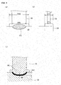
- FIG. 4 is a schematic view showing how to perform the breaking test.
- the ground electrode 30 was first bent inwardly from the state that the ground electrode 30 was perpendicular to the front end face 57 of the metal shell 50 ( FIG. 4(a) ) to the state that the ground electrode 30 was parallel to the front end face 57 of the metal shell 50 ( FIG. 4(b) ), and then, bent back to the state that the ground electrode 30 was perpendicular to the front end face 57 of the metal shell 50 ( FIG. 4(c) ).
- the operation of bending the ground electrode 30 from the state of FIG. 4(a) to the state of FIG. 4(b) was counted as 0.5 times; and the operation of bending the ground electrode 30 from the state of FIG. 4(b) to the state of FIG. 4(c) was counted as 0.5 times.
- the condition 1 will be first verified below.
- the minimum value of the embedment amount BD was 0.15 mm; and the maximum value of the embedment amount BD was 0.40 mm.
- the number of bending times was less than 2.5 in each of the samples where the embedment amount BD was out of the above range. It was confirmed by these results that it is possible to secure the joint strength between the ground electrode 30 and the metal shell 50 by controlling the embedment amount BD to be 0.15 to 0.40 mm.
- the condition 2 will be verified below.
- the condition 4 will be verified below.
- the minimum value of the fused layer thickness MH was 10 ⁇ m; and the maximum value of the fused layer thickness MH was 200 ⁇ m.
- the number of bending times was less than 2.5 in each of the samples where the fused layer thickness MH was out of the above range. It was confirmed by these results that it is possible to secure the joint strength between the ground electrode 30 and the metal shell 50 by controlling the fused layer thickness MH to be 10 to 200 ⁇ m. It is generally likely that, when the fused layer ML between the ground electrode 3 and the metal shell 50 is large in thickness, breakage of the ground electrode 30 will occur starting from such a part.
- the number of bending times was only 0.5 in the sample No. 13 where the fused layer thickness MH was 270 ⁇ m and was larger than those of the other samples.
- the fused layer ML can be made relatively small in thickness so as to secure the joint strength between the ground electrode 30 and the metal shell 50.
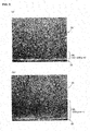
- FIG. 5(a) is an electron microscopic image of the cross section of the sample where the fused layer thickness MH satisfied the condition 4 (10 ⁇ m ⁇ MH ⁇ 200 ⁇ m); and FIG 5(b) is an electron microscopic image of the cross section of the sample where the fused layer thickness MH did not satisfy the condition 4.
- the fused layer thickness MH that is, the parameter of the condition 4 was determined by identifying a region of the fused layer where the crystal grain size was 20 ⁇ m or less on the cross-sectional image of FIG. 5 visually or by a computer, and then, measuring the thickness of this region on the cross-sectional image. By such measurement method, it was found that the grain size of the crystal in the fused layer ML was smaller than that in any portion of the ground electrode 30 other than the fused layer ML.
- FIG. 6(a) is a cross-sectional image of the sample where the supersaturated solid solution was observed.
- FIG. 6(b) is a cross-sectional image of the sample where the intermetallic compound of 5 ⁇ m or less crystal grain size was observed.
- FIG. 6(c) is a cross-sectional image of the sample where the intermetallic compound of 5 to 20 ⁇ m crystal grain size was observed.
- the supersaturated solid solution has the property of causing a solid solution of rare earth element by cooling rapidly after heating at 1300 to 1400°C.
- the presence or absence of the supersaturated solid solution can be judged accurately by performing such a treatment on the fused layer ML.
- the present invention is not limited to these exemplary embodiment and examples. Various modifications and variations of the present invention are possible without departing from the scope of the present invention.
- the number of the ground electrode 30 joined to the metal shell 50 is not limited to 1.
- a plurality of ground electrode 30 may be joined to the metal shell 50.
Landscapes
- Engineering & Computer Science (AREA)
- Chemical & Material Sciences (AREA)
- Combustion & Propulsion (AREA)
- Mechanical Engineering (AREA)
- General Engineering & Computer Science (AREA)
- Spark Plugs (AREA)
- Ignition Installations For Internal Combustion Engines (AREA)
Abstract
Description
- The present invention relates to a spark plug mounted to an internal combustion engine.
- In recent years, there has been a demand to increase the valve diameter of intake and exhaust valves for high-output performance of internal combustion engines. There has also been a demand to provide larger water jackets for efficient cooling of high-output internal combustion engines. In response to these demands, the installation spaces of spark plugs in the internal combustion engines are limited. It is thus required to decrease the diameter of spark plugs.
- It is further required that the spark plugs have high ignition performance in order to cope with the strong demand for low emissions from recent internal combustion engines. For the above reasons, the spark plug has a ground electrode of as large dimensions as possible welded to a metal shell even when the metal shell is reduced in diameter. However, the fused joint between the metal shell and the ground electrode decreases in size as the thickness of the ground electrode increases with increasing dimensions and becomes close to the thickness of the metal shell (see Patent Document 1). This leads to a deterioration in the joint strength between the metal shell and the ground electrode.
-
- Patent Document 1: Japanese Laid-Open Patent Publication No.
2003-223968 - Patent Document 2: Japanese Laid-Open Patent Publication No.
2003-59617 - Patent Document 3: Japanese Laid-Open Patent Publication No.
2009-16278 - Patent Document 4: Japanese Laid-Open Patent Publication No.
2005-339864 - In view of the above problems, it is an object of the present invention to provide a spark plug capable of securing the joint strength between a ground electrode and a metal shell even when the spark plug is reduced in diameter.
- The present invention has been made to solve at least part of the above problems and can be embodied in the following aspects or application examples.
- A spark plug, comprising: a center electrode extending in an axial direction of the spark plug; a ground electrode formed of a metal material containing 95 mass% or more of nickel; and a substantially cylindrical metal shell having a front end face to which one end of the ground electrode is welded, wherein an embedment amount BD, an original width EW1 and a deformation width EW2 satisfy the conditions: 0.15 mm ≤ BD ≤ 0.40 mm; and (EW2-EW1)/EW1 ≥ 0.1 where the embedment amount BD is a depth from the front end face of the metal shell to a portion of the ground electrode embedded most deeply in the metal shell by the welding of the ground electrode and the metal shell; the original width EW1 is a width of a portion of the ground electrode located closest to a portion of the ground electrode deformed by the welding; and the deformation width EW2 is a width of the portion of the ground electrode deformed by the welding at the front end face of the metal shell.
- In the above-configured spark plug, the ground electrode has an increased thermal conductivity due to its very high nickel content of 95 mass% or more and thus can be welded to the metal shell in such a manner as to embed the portion of the ground electrode in the metal shell. Even when the spark plug is reduced in diameter, it is possible to secure the joint strength between the ground electrode and the metal shell by setting the depth of embedment (embedment amount BD) and the original width EW1 and deformation width EW2 of the ground electrode so as to satisfy the above conditions (0.15 mm ≤ BD ≤ 0.40 mm and (EW2-EW1)/EW1≥0.1).
- The spark plug according to Application Example 1, wherein the original width EW1 and the deformation width EW2 satisfy the condition: (EW2-EW1)/EW1 ≥ 0.16.
It is possible to secure the joint strength between the ground electrode and the metal shell more assuredly by setting the original width EW1 and the deformation width EW2 of the ground electrode so as to satisfy the above condition. - The spark plug according to Application Example 1 or 2, wherein the spark plug has a removed surface region defined by removing, in the axial direction, at least a portion of a protruded part that has been formed in a thickness direction of the ground electrode by the welding of the ground electrode and the metal shell; and wherein a removed surface area CS and a ground electrode cross-sectional area ES satisfy the condition: CS/ES ≥ 1.2 where the removed surface area CS is an area of the removed surface region; and the ground electrode cross-sectional area ES is an area of a cross section taken perpendicular to the axial direction through the portion of the ground electrode located closest to the portion of the ground electrode deformed by the welding.
It is possible to secure the joint strength between the ground electrode and the metal shell more assuredly by setting the removed surface area CS and the ground electrode cross-sectional area ES so as to satisfy the above condition. - The spark plug according to Application Example 3, wherein the removed surface area CS and the ground electrode cross-sectional area ES satisfy the condition: CS/ES ≥ 1.6.
It is possible to secure the joint strength of the ground electrode and the metal shell more assuredly by setting the removed surface area CS and the ground electrode cross-sectional area ES so as to satisfy the above condition. - The spark plug according to any one of Application Examples 1 to 4, wherein the ground electrode contains a rare earth element; wherein the spark plug comprises, at the portion of the ground electrode embedded most deeply in the metal shell, a fused layer formed of a crystal containing therein the rear earth mental and having a grain size of 20 µm or less; and wherein a fused layer thickness MH satisfies the condition: 10 µm ≤ MH ≤ 200 µm where the fused layer thickness MH is a thickness of the fused layer in the axial direction.
As the rare earth element is contained in the ground electrode, the thermal conductivity of the ground electrode is made lower than that of the metal shell. This makes it easier to melt the metal shell so that the portion of the ground electrode can be favorably embedded in the metal shell by the welding. It is generally likely that, when the fused layer between the ground electrode and the metal shell is large in thickness, breakage of the ground electrode will occur starting from such a part. When the fused layer thickness MH falls within the above range, the fused layer can be made relatively small in thickness. It is thus possible to secure the joint strength between the ground electrode and the metal shell assuredly. - The spark plug according to Application Example 5, wherein the crystal is of a rare earth compound; and wherein the rare earth compound is a supersaturated solid solution containing the rare earth element.
By the presence of the supersaturated solid solution in the fused layer, the entry of foreign substance can be prevented so as to increase the grain bond strength of the fused layer. It is thus possible to secure the joint strength between the ground electrode and the metal shell more assuredly. - The spark plug according to Application Example 5, wherein the crystal is of a rare earth compound; and wherein the rare earth compound is an intermetallic compound containing the rare earth element and having a grain size of 5 µm or less.
By the presence of the intermetallic compound having a relatively small grain size of 5 µm or less in the fused layer, it is easier to distribute stress and is thus possible to secure the joint strength between the ground electrode and the metal shell more assuredly. - The spark plug according to any one of Application Examples 5 to 7, wherein the grain size of the crystal containing the rare earth element in the fused layer is smaller than that of a crystal containing the rare earth element in a portion of the ground electrode undeformed by the welding.
It is possible in this configuration to secure the joint strength between the ground electrode and the metal shell more assuredly. - The spark plug according to any one of Application Examples 5 to 8, wherein at least one of neodymium, yttrium and cerium is contained as the rare earth element.
By the addition of such a rare earth element to the ground electrode, it is possible to favorably embed the end portion of the ground electrode in the metal shell. - The present invention can be realized not only as the above-mentioned spark plug but also as a manufacturing method of a spark plug.
-
-
FIG. 1 is a schematic view, partly in section, of a spark plug according to one embodiment of the present invention. -
FIG. 2 is a schematic view showing a method for joining a rare earth element-containing ground electrode to a metal shell according to the one embodiment of the present invention. -
FIG. 3 is an enlarged view of a joint between the ground electrode and the metal shell according to the one embodiment of the present invention. -
FIG. 4 is a schematic view showing a breaking test method. -
FIG. 5 are images of cross sections of fused layers and vicinities thereof taken by an electron microscope. -
FIG. 6 are images of crystal structures taken at cross sections of fused layers by an electron microscope. - Hereinafter, an exemplary embodiment and examples of the present invention will be described below with reference to the drawings.
-
FIG. 1 is a schematic view, partly in section, of aspark plug 100 according to one embodiment of the present invention. In the following explanation, upper and lower sides ofFIG. 1 are referred to as front and rear sides with respect to the direction of an axis O of thespark plug 100, respectively. Thespark plug 100 includes aceramic insulator 10, acenter electrode 20, aground electrode 30, aterminal rod 40 and ametal shell 50. - The
center electrode 20 is a rod-shaped electrode that protrudes from a front end of theceramic insulator 10. Theterminal rod 40 is inserted in a rear side of theceramic insulator 10 so that thecenter electrode 20 is electrically connected to theterminal rod 40 within theceramic insulator 10. An outer circumference of thecenter electrode 20 is retained by theceramic insulator 10; and an outer circumference of theceramic insulator 10 is retained by themetal shell 50 at a position apart from theterminal rod 40. - The
ceramic insulator 10 is a cylindrical insulator that has, in the center thereof, anaxial hole 12 in which thecenter electrode 20 and the terminal rode 40 are inserted. Theceramic insulator 10 is formed by sintering ceramic material such as alumina. Theceramic insulator 10 includes amiddle body portion 19 located at an axially middle position thereof and having an enlarged outer diameter, arear body portion 18 located rear of themiddle body portion 19 so as to provide an insulation between theterminal rod 40 and themetal shell 50, afront body portion 17 located front of themiddle body portion 19 and having an outer diameter made smaller than that of therear body portion 18 and aleg portion 13 located front of thefront body portion 17 and having an outer diameter made smaller than that of thefront body portion 17 in such a manner that the outer diameter of theleg portion 13 gradually decreases toward thecenter electrode 20. - The
metal shell 50 is a cylindrical metal fixture that surrounds and retains therein a part of theceramic insulator 10 extending from a point on therear body portion 18 to theleg portion 13. In the present embodiment, themetal shell 50 is formed of low carbon steel. Themetal shell 50 includes atool engagement portion 51, a mountingthread portion 52 and aseal portion 54. Thetool engagement portion 51 of themetal shell 50 is engageable with a tool for mounting thespark plug 100 onto an engine head. The mountingthread portion 52 of themetal shell 50 has a screw thread screwed into a mounting thread hole of the engine head. Theseal portion 54 of themetal shell 50 is formed into a flange shape at a bottom of the mountingthread portion 52. Anannular gasket 5, which is formed by bending a plate material, is disposed between theseal portion 54 and the engine head (not shown). A front end face 57 of themetal shell 50 is formed into a hollow circle shape so that thecenter electrode 20 protrudes from theleg portion 13 of theceramic insulator 10 through the center of the front end face 57 of themetal shell 50. - The
center electrode 20 is a rod-shaped electrode including a bottomedcylindrical electrode body 21 and a core 25 having a higher thermal conductivity than that of theelectrode body 21 and embedded in theelectrode body 21. In the present embodiment, theelectrode body 21 is formed of a nickel alloy containing nickel as a main component; and thecore 25 is formed of copper or an alloy containing copper as a main component. Thecenter electrode 20 is inserted in theaxial hole 12 of theceramic insulator 10, with a front end of theelectrode body 21 protruding from theaxial hole 12 of theceramic insulator 10, and is electrically connected to theterminal rod 40 via aceramic resistor 3 and aseal member 4. - The
ground electrode 30 is joined at one end thereof to the front end face 57 of themetal shell 50 and is bent in such a manner that the other end of theground electrode 30 faces a front end portion of thecenter electrode 20. In the present embodiment, theground electrode 30 is formed of a nickel alloy containing 95 mass% or more of nickel (Ni) and 0.05 to 1.0 mass% of neodymium (Nd) as a rare earth element. As the rare earth element, yttrium (Y) and/or cerium (Ce) can be used in place of or in combination with neodymium. Theground electrode 30 may contain chromium (Cr) in addition to nickel and rare earth element. It is feasible to produce theground electrode 30 by, for example, melting a raw material having the above contents of nickel and neodymium in a vacuum melting furnace, casing the molten material into an ingot, and then, subjecting the ingot to hot working and drawing. -
FIG. 2 is a schematic view showing a method for joining the rare earth element-containingground electrode 30 to themetal shell 50. In the present embodiment, theground electrode 30 and themetal shell 50 are first held with upper andlower electrodes FIG. 2(a) . At this time, the front end face 57 of themetal shell 50 is spaced apart by 0.5 to 2.0 mm from a lower surface of theupper electrode 71 and by 5.0 to 30.0 mm from an upper surface of thelower electrode 72. Theground electrode 30 and themetal shell 50 are pressed together from upper and lower sides with the application of a pressure of 400 to 800 N by each of the twoelectrodes lower electrodes - The resistance welding of the
ground electrode 30 and themetal shell 50 is performed by supplying a current between the upper andlower electrodes inverter power supply 73 simultaneously with pressing theground electrode 30 and themetal shell 50 together by the upper andlower electrodes lower electrodes ground electrode 30 and themetal shell 50. After the current supply, theground electrode 30 and themetal shell 50 are held as they are by the upper andlower electrodes inverter power supply 73 in the present embodiment, it is feasible to use any other short-time/large-current power supply such as a transistor power supply or a condenser power supply. - By the above method, the
ground electrode 30 and themetal shell 50 are welded together in such a manner that a rear end of theground electrode 30 becomes embedded in themetal shell 50. In the present embodiment, the rear end of theground electrode 30 is embedded in themetal shell 50 because theground electrode 30 has an increased thermal conductivity due to its very high nickel content of 95 mass% or more and can easily transfer heat to themetal shell 50. It is also because the thermal conductivity of theground electrode 30 is made lower than that of themetal shell 50 by the addition of the rare earth element to theground electrode 30 so as to make it easier to melt themetal shell 50 than theground electrode 30 in the present embodiment. - Upon the welding of the
ground electrode 30 and themetal shell 50, welding burrs 80 (as a protruded part) occur on a front end portion of themetal shell 50 in a thickness direction of theground electrode 30 as shown inFIG. 2(b) . These welding burrs 80 are removed, by known machining process such as shearing or cutting, along inner and outer surfaces of themetal shell 50 in the direction of the axis O. There is thus obtained a joint assembly of theground electrode 30 and themetal shell 50 from which the welding burrs 80 have been removed as shown inFIG. 2(c) . Thespark plug 100 is completed by, after joining theground electrode 30 and themetal shell 50 together by the above method, assembling theceramic insulator 10, thecenter electrode 20 and the like in themetal shell 50. -
FIG. 3 is an enlarged view of the joint betweenground electrode 30 and themetal shell 50. More specifically,FIG. 3(a) is an enlarged view of the joint in a width direction of the ground electrode. In the following explanation, the width of a portion of theground electrode 30 located closest to a portion of theground electrode 30 deformed by the welding of theground electrode 30 and themetal shell 50 is called "original width EW1"; and the width of the portion of theground electrode 30 deformed by the welding of theground electrode 30 and themetal shell 50 at the front end face 57 of themetal shell 50 is called "deformation width EW2". Further, the surface area of the part from which the welding burrs 80 have been removed (seeFIG. 2 ) is called "removed surface area CS". The removed surface area CS refers to the sum of removed surface areas of theground electrode 30 and the inner and outer surfaces of themetal shell 50. -
FIG. 3(b) is an enlarged view of the joint in a thickness direction of theground electrode 30. The thickness of the portion of theground electrode 30 located closest to the portion of theground electrode 30 deformed by the welding of the ground electrode and themetal shell 50 is called "original thickness ET1"; and the thickness of the portion of theground electrode 30 deformed by the welding of theground electrode 30 and themetal shell 50 at the front end face 57 of the metal shell 50 (after the removal of the welding burrs) is called "deformation thickness ET2". The area of a cross section taken, in a direction perpendicular to the direction of the axis O, through the portion of theground electrode 30 located closest to the portion of theground electrode 30 deformed by the welding of theground electrode 30 and themetal shell 50 is called "ground electrode cross-sectional area ES". The ground electrode cross-sectional area ES is given by multiplication of the original width EW1 by the original thickness ET1. -
FIG 3(c) is an enlarged view of the joint in a width direction of theground electrode 30. When theground electrode 30 and themetal shell 50 are welded together by the above method ofFIG. 2 , there is a fused layer ML formed along a boundary between theground electrode 30 and themetal shell 50 at a position below (rear of) the front end face 57 of themetal shell 50 as shown inFIG. 3(c) . In the present embodiment, the fused layer ML refers to a region where the grain size of a crystal containing the rare earth element falls within the range of 20 µm or less at the boundary between theground electrode 30 and themetal shell 50. The depth from the front end face 57 of themetal shell 50 to a portion of the ground electrode 30 (including the fused layer ML) embedded most deeply in themetal shell 50 is called "embedment amount BD". Further, the thickness of the fused layer ML at the portion of theground electrode 30 embedded most deeply in themetal shell 50 from the front end face 57 of themetal shell 50 is called "fused layer thickness MH". - In the present embodiment, the
spark plug 100 is manufactured in such a manner that the respective parameters ofFIG. 3 satisfy the followingconditions 1 to 4. Thecondition 1 is set with respect to the embedment amount BD. The condition 2 is set with respect to the rate of deformation of theground electrode 30 in the width direction (hereinafter called "width-direction deformation rate"). Thecondition 3 is set with respect to the ratio of the removed surface area CS to the ground electrode cross-sectional area ES (hereinafter referred to "removed surface area ratio"). Thecondition 4 is set with respect to the fused layer thickness MH. -
- Condition 1: 0.15 mm ≤ BD ≤ 0.40 mm
- Condition 2: (EW2-EW1)/EW1≥ 0.1
- Condition 3: 1.2 ≤ CS/ES ≤ 1.6
- Condition 4: 10 µm ≤ MH ≤ 200 µm
- The
spark plug 100 is also manufactured in such a manner that the crystal structure of the fused layer ML satisfies thefollowing condition 5 in the present embodiment. - Condition 5: The crystal of the fused layer is of a rare earth compound that is either a supersaturated solid solution containing the rare earth element or an intermetallic compound containing the rare earth element and having a grain size of 5 µm or less.
- It is possible for the
spark plug 100 of the present embodiment to secure the joint strength between the ground electrode and the metal shell by satisfaction of the above conditions. The basis for the above conditions will be explained below with reference to experimental results. - A plurality of kinds of the
ground electrode 30 having different original thickness ET1 and original width EW1 (i.e. different cross-sectional area) were prepared and each resistance welded to theground electrode 30 by changing the current supplied between theelectrodes ground electrode 30, thereby producing a plurality of kinds of joint assemblies of theground electrode 30 and metal shell 50 (hereinafter called "samples") in which the parameters of theabove conditions 1 to 4 were varied. Each of the above-produced samples was subjected to a breaking test. In the breaking test, theground electrode 30 was bent several times. The sample where no breakage occurred in theground electrode 30 even when theground electrode 30 was bent 2.5 times or more was judged as "passing (⊚)"; whereas the sample where a breakage occurred in theground electrode 30 when the number of bending times of theground electrode 30 was less than 2.5 was judged as "failing (×)". The number of bending times of 2.5 corresponds to a strength of theground electrode 30 that can withstand normal driving of 100,000 km. -
FIG. 4 is a schematic view showing how to perform the breaking test. In the breaking test, theground electrode 30 was first bent inwardly from the state that theground electrode 30 was perpendicular to the front end face 57 of the metal shell 50 (FIG. 4(a) ) to the state that theground electrode 30 was parallel to the front end face 57 of the metal shell 50 (FIG. 4(b) ), and then, bent back to the state that theground electrode 30 was perpendicular to the front end face 57 of the metal shell 50 (FIG. 4(c) ). With regard to the number of bending of theground electrode 30, the operation of bending theground electrode 30 from the state ofFIG. 4(a) to the state ofFIG. 4(b) was counted as 0.5 times; and the operation of bending theground electrode 30 from the state ofFIG. 4(b) to the state ofFIG. 4(c) was counted as 0.5 times. - The results of the above breaking test are indicated in TABLE 1. As indicated in TABLE 1, the breaking test was performed on the samples in which the original thickness ET1 and original width EW1 of the
ground electrode 30 were follows: ET1 = 1.1 mm and EW1 = 2.2 mm (sample Nos. 1 to 4); ET1 = 1.3 mm and EW1 = 2.7 mm (sample Nos. 5 to 9); and ET1 = 1.6 mm and EW1 = 2.8 mm (sample Nos. 10 to 14).

- In each of the sample Nos. 2, 3, 4, 7, 8, 9, 11, 12 and 14, the number of bending times of 2.5 or more was secured (the judgment result was ⊚) in the breaking test as shown in TABLE 1. Hereinafter, the samples judged as ⊚ will be verified for the respective parameter ranges of the above conditions.
- The
condition 1 will be first verified below. In the samples where the number of bending times was 2.5 times or more, the minimum value of the embedment amount BD was 0.15 mm; and the maximum value of the embedment amount BD was 0.40 mm. By contrast, the number of bending times was less than 2.5 in each of the samples where the embedment amount BD was out of the above range. It was confirmed by these results that it is possible to secure the joint strength between theground electrode 30 and themetal shell 50 by controlling the embedment amount BD to be 0.15 to 0.40 mm. - Next, the condition 2 will be verified below. In the samples where the number of bending times was 2.5 times or more, the minimum value of the width-direction deformation rate (= (EW2-EW1)/EW1) was 0.10 (= 10%); and the maximum value of the width-direction deformation rate was 0.52 (= 52%). It was thus confirmed that it is necessary to control the width-direction deformation rate to be at least 0.10 (preferably 0.16 or higher) in order to secure the number of bending times of 2.5 or more.
- The
condition 3 will be next verified below. In the samples where the number of bending times was 2.5 or more, the minimum value of the removed surface area ratio (= CS/ES) was 1.2 (= 120%); and the maximum value of the removed surface area ratio was 1.6 (=160%). By contrast, the number of bending times was less than 2.5 in each of the samples where the removed surface area ratio was out of the above range. It was confirmed by these results that it is possible to secure the joint strength between theground electrode 30 and themetal shell 50 by controlling the removed surface area ratio to be 1.2 to 1.6. - The
condition 4 will be verified below. In the samples where the number of bending times was 2.5 or more, the minimum value of the fused layer thickness MH was 10 µm; and the maximum value of the fused layer thickness MH was 200 µm. The number of bending times was less than 2.5 in each of the samples where the fused layer thickness MH was out of the above range. It was confirmed by these results that it is possible to secure the joint strength between theground electrode 30 and themetal shell 50 by controlling the fused layer thickness MH to be 10 to 200 µm. It is generally likely that, when the fused layer ML between theground electrode 3 and themetal shell 50 is large in thickness, breakage of theground electrode 30 will occur starting from such a part. For instance, the number of bending times was only 0.5 in the sample No. 13 where the fused layer thickness MH was 270 µm and was larger than those of the other samples. When fused layer thickness MH falls within the above range, the fused layer ML can be made relatively small in thickness so as to secure the joint strength between theground electrode 30 and themetal shell 50. - Cross-sectional images of fused layers MS and vicinities thereof taken by an electron microscope are shown in
FIG. 5 . More specifically,FIG. 5(a) is an electron microscopic image of the cross section of the sample where the fused layer thickness MH satisfied the condition 4 (10 µm ≤ MH ≤ 200 µm); andFIG 5(b) is an electron microscopic image of the cross section of the sample where the fused layer thickness MH did not satisfy thecondition 4. The fused layer thickness MH, that is, the parameter of thecondition 4 was determined by identifying a region of the fused layer where the crystal grain size was 20 µm or less on the cross-sectional image ofFIG. 5 visually or by a computer, and then, measuring the thickness of this region on the cross-sectional image. By such measurement method, it was found that the grain size of the crystal in the fused layer ML was smaller than that in any portion of theground electrode 30 other than the fused layer ML. - Next, the
condition 5 will be verified below. Among the samples shown in TABLE 1, the typical four samples where the judgment result was ⊚ (sample Nos. 2, 8, 12 and 14) and the typical two samples where the judgment result was × (sample Nos. 1 and 13) were selected. The crystal structure of the cross section of the fused layer ML in each of the selected samples was observed by an electron microscope. The enlarged image of the crystal structure taken by the electron microscope was checked for the presence or absence of a supersaturated solid solution or intermetallic compound of 5 µm or less crystal grain size as the rare earth compound containing the rare earth element in the fused layer ML. The check results are indicated in TABLE 2. Further, the electron microscopic images of the crystal structures at the cross sections of the fused layers ML are shown inFIG. 6 . -
TABLE 2 Sample No. Judgment result Fused layer MH (µm) Supersaturated solid solution Intermetallic compound Crystal grain seize: 5 µm or less Crystal grain size: 5 to 20 µm 1 × 2 absent absent present 2 ⊚ 10 absent present absent 8 ⊚ 80 present present absent 12 ⊚ 160 present absent absent 13 × 270 absent absent present 14 ⊚ 200 present absent absent - As shown in TABLE 2, either the supersaturated solid solution or the intermetallic compound of 5 µm or less crystal grain size was observed in the fused layer ML in each of the samples where the judgment result was ⊚ (samples Nos. 2, 8, 12 and 14).
FIG. 6(a) is a cross-sectional image of the sample where the supersaturated solid solution was observed.FIG. 6(b) is a cross-sectional image of the sample where the intermetallic compound of 5 µm or less crystal grain size was observed. The intermetallic compound of 5 µm or less crystal grain size was identified in the sample No. 2 (MH = 10 µm) where the fused layer thickness MH was relatively small, whereas the supersaturated solid solution was identified in the sample No. 12 (MH = 160 µm) and No. 14 (MH = 200 µm) where the fused layer thickness was relatively large. Both of the supersaturated solid solution and the intermetallic compound of 5 µm or less crystal grain size were identified in the sample No. 8 (MH = 80 µm) where the fused layer thickness MH was between those of the above samples. - By contrast, the intermetallic compound having a relatively large crystal grain size of 5 to 20 µm was observed in the fused layer in each of the samples where the judgment result was × (sample Nos. 1 and 13).
FIG. 6(c) is a cross-sectional image of the sample where the intermetallic compound of 5 to 20 µm crystal grain size was observed. - It was confirmed by the test results of TABLE 2 that it is possible to secure the joint strength between the
ground electrode 30 and themetal shell 50 by the presence of at least one of the supersaturated solid solution containing the rare earth element and the intermetallic compound containing the rare earth element and having a crystal grain size of 5 µm or less in the fused layer ML. The reason for this is assumed to be that: by the presence of the supersaturated solid solution in the fused layer ML, the entry of foreign substance can be prevented so as to increase the grain bond strength of the fused layer; and the stress can be easily distributed by the presence of the intermetallic compound having a relatively small grain size of 5 µm or less in the fused layer ML. It is herein noted that, although the crystal grain size of the supersaturated solid solution cannot be observed because of the chemical properties of the supersaturated solid solution, the supersaturated solid solution has the property of causing a solid solution of rare earth element by cooling rapidly after heating at 1300 to 1400°C. Thus, the presence or absence of the supersaturated solid solution can be judged accurately by performing such a treatment on the fused layer ML. - As is evident from the experimental results of TABLES 1 and 2, it is possible to secure the joint strength between the
ground electrode 30 and themetal shell 50 by satisfaction of the above-mentionedconditions 1 to 5 (at least theconditions 1 and 2) even when thespark plug 100 is downsized to e.g. a small diameter level of M12, M10, M8 or smaller. - Although the specific exemplary embodiment and examples of the present invention has been described above, the present invention is not limited to these exemplary embodiment and examples. Various modifications and variations of the present invention are possible without departing from the scope of the present invention. For example, the number of the
ground electrode 30 joined to themetal shell 50 is not limited to 1. A plurality ofground electrode 30 may be joined to themetal shell 50. -
- 100:
- Spark plug
- 3:
- Ceramic resistor
- 4:
- Seal member
- 10:
- Ceramic insulator
- 12:
- Axial hole
- 13:
- Leg portion
- 17:
- Front body portion
- 18:
- Rear body portion
- 19:
- Middle body portion
- 20:
- Center electrode
- 21:
- Electrode body
- 25:
- Core
- 30:
- Ground electrode
- 40:
- Terminal rod
- 50:
- Metal shell
- 51:
- Tool engaging portion
- 52:
- Mounting thread portion
- 54:
- Seal portion
- 57:
- Front end face
- 71:
- Upper electrode
- 72:
- Lower electrode
- 73:
- Alternating inverter power supply
- 80:
- Welding burr
Claims (9)
- A spark plug, comprising:a center electrode extending in an axial direction of the spark plug;a ground electrode formed of a metal material containing 95 mass% or more of nickel; anda substantially cylindrical metal shell having a front end face to which one end of the ground electrode is welded,wherein an embedment amount BD, an original width EW1 and a deformation width EW2 satisfy the conditions:

and
where the embedment amount BD is a depth from the front end face of the metal shell to a portion of the ground electrode embedded most deeply in the metal shell by the welding of the ground electrode and the metal shell; the original width EW1 is a width of a portion of the ground electrode located closest to a portion of the ground electrode deformed by the welding; and the deformation width EW2 is a width of the portion of the ground electrode deformed by the welding at the front end face of the metal shell. - The spark plug according to claim 1, wherein the original width EW1 and the deformation width EW2 satisfy the condition: (EW2-EW1)/EW1 ≥ 0.16.
- The spark plug according to claim 1 or 2, wherein the spark plug has a removed surface region defined by removing, in the axial direction, at least a portion of a protruded part that has been formed in a thickness direction of the ground electrode by the welding of the ground electrode and the metal shell; and wherein a removed surface area CS and a ground electrode cross-sectional area ES satisfy the condition: CS/ES ≥1.2 where the removed surface area CS is an area of the removed surface region; and the ground electrode cross-sectional area ES is an area of a cross section taken perpendicular to the axial direction through the portion of the ground electrode located closest to the portion of the ground electrode deformed by the welding.
- The spark plug according to claim 3, wherein the removed surface area CS and the ground electrode cross-sectional area ES satisfy the condition: CS/ES ≥ 1.6.
- The spark plug according to any one of claims 1 to 4, wherein the ground electrode contains a rare earth element; wherein the spark plug comprises, at the portion of the ground electrode embedded most deeply in the metal shell, a fused layer formed of a crystal containing therein the rear earth mental and having a grain size of 20 µm or less; and wherein a fused layer thickness MH satisfies the condition: 10 µm ≤ MH ≤ 200 µm where the fused layer thickness MH is a thickness of the fused layer in the axial direction.
- The spark plug according to claim 5, wherein the crystal is of a rare earth compound; and wherein the rare earth compound is a supersaturated solid solution containing the rare earth element.
- The spark plug according to claim 5, wherein the crystal is of a rare earth compound; and wherein the rare earth compound is an intermetallic compound containing the rare earth element and having a grain size of 5 µm or less.
- The spark plug according to any one of claims 5 to 7, wherein the grain size of the crystal containing the rare earth element in the fused layer is smaller than that of a crystal containing the rare earth element in a portion of the ground electrode undeformed by the welding.
- The spark plug according to any one of claims 5 to 8, wherein at least one of neodymium, yttrium and cerium is contained as the rare earth element.
Applications Claiming Priority (2)
| Application Number | Priority Date | Filing Date | Title |
|---|---|---|---|
| JP2010110857 | 2010-05-13 | ||
| PCT/JP2011/002556 WO2011142106A1 (en) | 2010-05-13 | 2011-05-06 | Spark plug |
Publications (3)
| Publication Number | Publication Date |
|---|---|
| EP2571118A1 true EP2571118A1 (en) | 2013-03-20 |
| EP2571118A4 EP2571118A4 (en) | 2014-06-25 |
| EP2571118B1 EP2571118B1 (en) | 2019-08-14 |
Family
ID=44914166
Family Applications (1)
| Application Number | Title | Priority Date | Filing Date |
|---|---|---|---|
| EP11780365.0A Active EP2571118B1 (en) | 2010-05-13 | 2011-05-06 | Spark plug |
Country Status (6)
| Country | Link |
|---|---|
| US (1) | US9252568B2 (en) |
| EP (1) | EP2571118B1 (en) |
| JP (1) | JP5144818B2 (en) |
| KR (1) | KR101397895B1 (en) |
| CN (1) | CN102893470B (en) |
| WO (1) | WO2011142106A1 (en) |
Cited By (1)
| Publication number | Priority date | Publication date | Assignee | Title |
|---|---|---|---|---|
| EP2768094A3 (en) * | 2013-02-13 | 2015-01-28 | NGK Spark Plug Co., Ltd. | Spark plug and method of manufacturing the same |
Families Citing this family (3)
| Publication number | Priority date | Publication date | Assignee | Title |
|---|---|---|---|---|
| JP5789227B2 (en) * | 2012-07-23 | 2015-10-07 | 日本特殊陶業株式会社 | Spark plug |
| JP5903008B2 (en) * | 2012-07-23 | 2016-04-13 | 日本特殊陶業株式会社 | Spark plug |
| JP5996578B2 (en) * | 2014-05-21 | 2016-09-21 | 日本特殊陶業株式会社 | Manufacturing method of spark plug |
Family Cites Families (11)
| Publication number | Priority date | Publication date | Assignee | Title |
|---|---|---|---|---|
| JPH02121289A (en) * | 1988-10-31 | 1990-05-09 | Ngk Spark Plug Co Ltd | Manufacture and welding of outside electrode of spark plug, with good heat-conduction metal wrapped therein |
| US5530313A (en) * | 1994-10-24 | 1996-06-25 | General Motors Corporation | Spark plug with copper cored ground electrode and a process of welding the electrode to a spark plug shell |
| US6285008B1 (en) * | 2000-01-11 | 2001-09-04 | Federal-Mogul World Wide, Inc. | Ignition plug and method of manufacture |
| US20010030494A1 (en) | 2000-01-24 | 2001-10-18 | Keiji Kanao | Ground electrode for spark plug, spark plug and method of manufacturing the same |
| JP2001284013A (en) | 2000-01-24 | 2001-10-12 | Denso Corp | Ground electrode, spark plug using this ground electrode, and method of manufacturing the same |
| JP4507475B2 (en) | 2001-08-22 | 2010-07-21 | 株式会社デンソー | Spark plug and manufacturing method thereof |
| JP4064114B2 (en) * | 2002-01-31 | 2008-03-19 | 日本特殊陶業株式会社 | Manufacturing method of spark plug |
| JP4375119B2 (en) | 2004-05-25 | 2009-12-02 | 株式会社デンソー | Spark plug |
| JP4706441B2 (en) * | 2004-11-04 | 2011-06-22 | 日立金属株式会社 | Spark plug electrode material |
| JP4413951B2 (en) | 2007-07-06 | 2010-02-10 | 日本特殊陶業株式会社 | Spark plug |
| JP4804524B2 (en) | 2008-11-19 | 2011-11-02 | 日本特殊陶業株式会社 | Spark plug for internal combustion engine and method for manufacturing the same |
-
2011
- 2011-05-06 WO PCT/JP2011/002556 patent/WO2011142106A1/en not_active Ceased
- 2011-05-06 JP JP2011543750A patent/JP5144818B2/en active Active
- 2011-05-06 CN CN201180023877.7A patent/CN102893470B/en active Active
- 2011-05-06 EP EP11780365.0A patent/EP2571118B1/en active Active
- 2011-05-06 US US13/697,385 patent/US9252568B2/en active Active
- 2011-05-06 KR KR1020127032387A patent/KR101397895B1/en not_active Expired - Fee Related
Cited By (1)
| Publication number | Priority date | Publication date | Assignee | Title |
|---|---|---|---|---|
| EP2768094A3 (en) * | 2013-02-13 | 2015-01-28 | NGK Spark Plug Co., Ltd. | Spark plug and method of manufacturing the same |
Also Published As
| Publication number | Publication date |
|---|---|
| CN102893470A (en) | 2013-01-23 |
| CN102893470B (en) | 2014-03-12 |
| US20130069517A1 (en) | 2013-03-21 |
| JPWO2011142106A1 (en) | 2013-07-22 |
| US9252568B2 (en) | 2016-02-02 |
| WO2011142106A1 (en) | 2011-11-17 |
| JP5144818B2 (en) | 2013-02-13 |
| EP2571118B1 (en) | 2019-08-14 |
| KR101397895B1 (en) | 2014-05-20 |
| KR20130018924A (en) | 2013-02-25 |
| EP2571118A4 (en) | 2014-06-25 |
Similar Documents
| Publication | Publication Date | Title |
|---|---|---|
| JP5341752B2 (en) | Spark plug for internal combustion engine and method for manufacturing the same | |
| EP2211432B1 (en) | Spark plug for internal combustion engine | |
| EP2658051B1 (en) | Spark plug and manufacturing method therefor | |
| EP2408071A1 (en) | Spark plug for internal combustion engine and method of manufacturing same | |
| US9270087B2 (en) | Spark plug with improved ground electrode joined to metal shell | |
| EP2571118B1 (en) | Spark plug | |
| EP2190084B1 (en) | Spark plug | |
| JP4956579B2 (en) | Spark plug for internal combustion engine and method for manufacturing the same | |
| EP2352212A1 (en) | Spark plug and method for manufacturing the same | |
| EP3065238B1 (en) | Spark plug | |
| JP2013004412A (en) | Spark plug | |
| EP2624383B1 (en) | Spark plug | |
| CN102844946B (en) | Spark plug | |
| US10290999B2 (en) | Spark plug | |
| JP4644139B2 (en) | Spark plug for internal combustion engine and method for manufacturing the same | |
| JP5564070B2 (en) | Spark plug | |
| JP2007227187A (en) | Spark plug for internal combustion engine and method for manufacturing the same |
Legal Events
| Date | Code | Title | Description |
|---|---|---|---|
| PUAI | Public reference made under article 153(3) epc to a published international application that has entered the european phase |
Free format text: ORIGINAL CODE: 0009012 |
|
| 17P | Request for examination filed |
Effective date: 20121113 |
|
| AK | Designated contracting states |
Kind code of ref document: A1 Designated state(s): AL AT BE BG CH CY CZ DE DK EE ES FI FR GB GR HR HU IE IS IT LI LT LU LV MC MK MT NL NO PL PT RO RS SE SI SK SM TR |
|
| DAX | Request for extension of the european patent (deleted) | ||
| A4 | Supplementary search report drawn up and despatched |
Effective date: 20140527 |
|
| RIC1 | Information provided on ipc code assigned before grant |
Ipc: H01T 13/32 20060101AFI20140521BHEP Ipc: F02P 13/00 20060101ALI20140521BHEP Ipc: H01T 13/39 20060101ALI20140521BHEP |
|
| GRAP | Despatch of communication of intention to grant a patent |
Free format text: ORIGINAL CODE: EPIDOSNIGR1 |
|
| STAA | Information on the status of an ep patent application or granted ep patent |
Free format text: STATUS: GRANT OF PATENT IS INTENDED |
|
| INTG | Intention to grant announced |
Effective date: 20190412 |
|
| GRAS | Grant fee paid |
Free format text: ORIGINAL CODE: EPIDOSNIGR3 |
|
| GRAA | (expected) grant |
Free format text: ORIGINAL CODE: 0009210 |
|
| STAA | Information on the status of an ep patent application or granted ep patent |
Free format text: STATUS: THE PATENT HAS BEEN GRANTED |
|
| AK | Designated contracting states |
Kind code of ref document: B1 Designated state(s): AL AT BE BG CH CY CZ DE DK EE ES FI FR GB GR HR HU IE IS IT LI LT LU LV MC MK MT NL NO PL PT RO RS SE SI SK SM TR |
|
| REG | Reference to a national code |
Ref country code: GB Ref legal event code: FG4D |
|
| REG | Reference to a national code |
Ref country code: CH Ref legal event code: EP Ref country code: AT Ref legal event code: REF Ref document number: 1168141 Country of ref document: AT Kind code of ref document: T Effective date: 20190815 |
|
| REG | Reference to a national code |
Ref country code: DE Ref legal event code: R096 Ref document number: 602011061287 Country of ref document: DE |
|
| REG | Reference to a national code |
Ref country code: IE Ref legal event code: FG4D |
|
| REG | Reference to a national code |
Ref country code: NL Ref legal event code: MP Effective date: 20190814 |
|
| REG | Reference to a national code |
Ref country code: LT Ref legal event code: MG4D |
|
| PG25 | Lapsed in a contracting state [announced via postgrant information from national office to epo] |
Ref country code: BG Free format text: LAPSE BECAUSE OF FAILURE TO SUBMIT A TRANSLATION OF THE DESCRIPTION OR TO PAY THE FEE WITHIN THE PRESCRIBED TIME-LIMIT Effective date: 20191114 Ref country code: NL Free format text: LAPSE BECAUSE OF FAILURE TO SUBMIT A TRANSLATION OF THE DESCRIPTION OR TO PAY THE FEE WITHIN THE PRESCRIBED TIME-LIMIT Effective date: 20190814 Ref country code: SE Free format text: LAPSE BECAUSE OF FAILURE TO SUBMIT A TRANSLATION OF THE DESCRIPTION OR TO PAY THE FEE WITHIN THE PRESCRIBED TIME-LIMIT Effective date: 20190814 Ref country code: HR Free format text: LAPSE BECAUSE OF FAILURE TO SUBMIT A TRANSLATION OF THE DESCRIPTION OR TO PAY THE FEE WITHIN THE PRESCRIBED TIME-LIMIT Effective date: 20190814 Ref country code: NO Free format text: LAPSE BECAUSE OF FAILURE TO SUBMIT A TRANSLATION OF THE DESCRIPTION OR TO PAY THE FEE WITHIN THE PRESCRIBED TIME-LIMIT Effective date: 20191114 Ref country code: PT Free format text: LAPSE BECAUSE OF FAILURE TO SUBMIT A TRANSLATION OF THE DESCRIPTION OR TO PAY THE FEE WITHIN THE PRESCRIBED TIME-LIMIT Effective date: 20191216 Ref country code: LT Free format text: LAPSE BECAUSE OF FAILURE TO SUBMIT A TRANSLATION OF THE DESCRIPTION OR TO PAY THE FEE WITHIN THE PRESCRIBED TIME-LIMIT Effective date: 20190814 Ref country code: FI Free format text: LAPSE BECAUSE OF FAILURE TO SUBMIT A TRANSLATION OF THE DESCRIPTION OR TO PAY THE FEE WITHIN THE PRESCRIBED TIME-LIMIT Effective date: 20190814 |
|
| REG | Reference to a national code |
Ref country code: AT Ref legal event code: MK05 Ref document number: 1168141 Country of ref document: AT Kind code of ref document: T Effective date: 20190814 |
|
| PG25 | Lapsed in a contracting state [announced via postgrant information from national office to epo] |
Ref country code: LV Free format text: LAPSE BECAUSE OF FAILURE TO SUBMIT A TRANSLATION OF THE DESCRIPTION OR TO PAY THE FEE WITHIN THE PRESCRIBED TIME-LIMIT Effective date: 20190814 Ref country code: ES Free format text: LAPSE BECAUSE OF FAILURE TO SUBMIT A TRANSLATION OF THE DESCRIPTION OR TO PAY THE FEE WITHIN THE PRESCRIBED TIME-LIMIT Effective date: 20190814 Ref country code: GR Free format text: LAPSE BECAUSE OF FAILURE TO SUBMIT A TRANSLATION OF THE DESCRIPTION OR TO PAY THE FEE WITHIN THE PRESCRIBED TIME-LIMIT Effective date: 20191115 Ref country code: RS Free format text: LAPSE BECAUSE OF FAILURE TO SUBMIT A TRANSLATION OF THE DESCRIPTION OR TO PAY THE FEE WITHIN THE PRESCRIBED TIME-LIMIT Effective date: 20190814 Ref country code: IS Free format text: LAPSE BECAUSE OF FAILURE TO SUBMIT A TRANSLATION OF THE DESCRIPTION OR TO PAY THE FEE WITHIN THE PRESCRIBED TIME-LIMIT Effective date: 20191214 Ref country code: AL Free format text: LAPSE BECAUSE OF FAILURE TO SUBMIT A TRANSLATION OF THE DESCRIPTION OR TO PAY THE FEE WITHIN THE PRESCRIBED TIME-LIMIT Effective date: 20190814 |
|
| PG25 | Lapsed in a contracting state [announced via postgrant information from national office to epo] |
Ref country code: TR Free format text: LAPSE BECAUSE OF FAILURE TO SUBMIT A TRANSLATION OF THE DESCRIPTION OR TO PAY THE FEE WITHIN THE PRESCRIBED TIME-LIMIT Effective date: 20190814 |
|
| PG25 | Lapsed in a contracting state [announced via postgrant information from national office to epo] |
Ref country code: DK Free format text: LAPSE BECAUSE OF FAILURE TO SUBMIT A TRANSLATION OF THE DESCRIPTION OR TO PAY THE FEE WITHIN THE PRESCRIBED TIME-LIMIT Effective date: 20190814 Ref country code: IT Free format text: LAPSE BECAUSE OF FAILURE TO SUBMIT A TRANSLATION OF THE DESCRIPTION OR TO PAY THE FEE WITHIN THE PRESCRIBED TIME-LIMIT Effective date: 20190814 Ref country code: AT Free format text: LAPSE BECAUSE OF FAILURE TO SUBMIT A TRANSLATION OF THE DESCRIPTION OR TO PAY THE FEE WITHIN THE PRESCRIBED TIME-LIMIT Effective date: 20190814 Ref country code: EE Free format text: LAPSE BECAUSE OF FAILURE TO SUBMIT A TRANSLATION OF THE DESCRIPTION OR TO PAY THE FEE WITHIN THE PRESCRIBED TIME-LIMIT Effective date: 20190814 Ref country code: RO Free format text: LAPSE BECAUSE OF FAILURE TO SUBMIT A TRANSLATION OF THE DESCRIPTION OR TO PAY THE FEE WITHIN THE PRESCRIBED TIME-LIMIT Effective date: 20190814 Ref country code: PL Free format text: LAPSE BECAUSE OF FAILURE TO SUBMIT A TRANSLATION OF THE DESCRIPTION OR TO PAY THE FEE WITHIN THE PRESCRIBED TIME-LIMIT Effective date: 20190814 |
|
| PG25 | Lapsed in a contracting state [announced via postgrant information from national office to epo] |
Ref country code: IS Free format text: LAPSE BECAUSE OF FAILURE TO SUBMIT A TRANSLATION OF THE DESCRIPTION OR TO PAY THE FEE WITHIN THE PRESCRIBED TIME-LIMIT Effective date: 20200224 Ref country code: SK Free format text: LAPSE BECAUSE OF FAILURE TO SUBMIT A TRANSLATION OF THE DESCRIPTION OR TO PAY THE FEE WITHIN THE PRESCRIBED TIME-LIMIT Effective date: 20190814 Ref country code: CZ Free format text: LAPSE BECAUSE OF FAILURE TO SUBMIT A TRANSLATION OF THE DESCRIPTION OR TO PAY THE FEE WITHIN THE PRESCRIBED TIME-LIMIT Effective date: 20190814 Ref country code: SM Free format text: LAPSE BECAUSE OF FAILURE TO SUBMIT A TRANSLATION OF THE DESCRIPTION OR TO PAY THE FEE WITHIN THE PRESCRIBED TIME-LIMIT Effective date: 20190814 |
|
| REG | Reference to a national code |
Ref country code: DE Ref legal event code: R097 Ref document number: 602011061287 Country of ref document: DE |
|
| PLBE | No opposition filed within time limit |
Free format text: ORIGINAL CODE: 0009261 |
|
| STAA | Information on the status of an ep patent application or granted ep patent |
Free format text: STATUS: NO OPPOSITION FILED WITHIN TIME LIMIT |
|
| PG2D | Information on lapse in contracting state deleted |
Ref country code: IS |
|
| 26N | No opposition filed |
Effective date: 20200603 |
|
| PG25 | Lapsed in a contracting state [announced via postgrant information from national office to epo] |
Ref country code: SI Free format text: LAPSE BECAUSE OF FAILURE TO SUBMIT A TRANSLATION OF THE DESCRIPTION OR TO PAY THE FEE WITHIN THE PRESCRIBED TIME-LIMIT Effective date: 20190814 |
|
| PG25 | Lapsed in a contracting state [announced via postgrant information from national office to epo] |
Ref country code: LI Free format text: LAPSE BECAUSE OF NON-PAYMENT OF DUE FEES Effective date: 20200531 Ref country code: MC Free format text: LAPSE BECAUSE OF FAILURE TO SUBMIT A TRANSLATION OF THE DESCRIPTION OR TO PAY THE FEE WITHIN THE PRESCRIBED TIME-LIMIT Effective date: 20190814 Ref country code: CH Free format text: LAPSE BECAUSE OF NON-PAYMENT OF DUE FEES Effective date: 20200531 |
|
| REG | Reference to a national code |
Ref country code: BE Ref legal event code: MM Effective date: 20200531 |
|
| GBPC | Gb: european patent ceased through non-payment of renewal fee |
Effective date: 20200506 |
|
| PG25 | Lapsed in a contracting state [announced via postgrant information from national office to epo] |
Ref country code: LU Free format text: LAPSE BECAUSE OF NON-PAYMENT OF DUE FEES Effective date: 20200506 |
|
| PG25 | Lapsed in a contracting state [announced via postgrant information from national office to epo] |
Ref country code: GB Free format text: LAPSE BECAUSE OF NON-PAYMENT OF DUE FEES Effective date: 20200506 Ref country code: FR Free format text: LAPSE BECAUSE OF NON-PAYMENT OF DUE FEES Effective date: 20200531 Ref country code: IE Free format text: LAPSE BECAUSE OF NON-PAYMENT OF DUE FEES Effective date: 20200506 |
|
| PG25 | Lapsed in a contracting state [announced via postgrant information from national office to epo] |
Ref country code: BE Free format text: LAPSE BECAUSE OF NON-PAYMENT OF DUE FEES Effective date: 20200531 |
|
| PG25 | Lapsed in a contracting state [announced via postgrant information from national office to epo] |
Ref country code: MT Free format text: LAPSE BECAUSE OF FAILURE TO SUBMIT A TRANSLATION OF THE DESCRIPTION OR TO PAY THE FEE WITHIN THE PRESCRIBED TIME-LIMIT Effective date: 20190814 Ref country code: CY Free format text: LAPSE BECAUSE OF FAILURE TO SUBMIT A TRANSLATION OF THE DESCRIPTION OR TO PAY THE FEE WITHIN THE PRESCRIBED TIME-LIMIT Effective date: 20190814 |
|
| PG25 | Lapsed in a contracting state [announced via postgrant information from national office to epo] |
Ref country code: MK Free format text: LAPSE BECAUSE OF FAILURE TO SUBMIT A TRANSLATION OF THE DESCRIPTION OR TO PAY THE FEE WITHIN THE PRESCRIBED TIME-LIMIT Effective date: 20190814 |
|
| P01 | Opt-out of the competence of the unified patent court (upc) registered |
Effective date: 20230512 |
|
| REG | Reference to a national code |
Ref country code: DE Ref legal event code: R081 Ref document number: 602011061287 Country of ref document: DE Owner name: NITERRA CO., LTD., NAGOYA-SHI, JP Free format text: FORMER OWNER: NGK SPARKPLUG CO., LTD., NAGOYA-SHI, AICHI, JP |
|
| PGFP | Annual fee paid to national office [announced via postgrant information from national office to epo] |
Ref country code: DE Payment date: 20250402 Year of fee payment: 15 |