EP2571046A1 - Transfer device - Google Patents
Transfer device Download PDFInfo
- Publication number
- EP2571046A1 EP2571046A1 EP10851352A EP10851352A EP2571046A1 EP 2571046 A1 EP2571046 A1 EP 2571046A1 EP 10851352 A EP10851352 A EP 10851352A EP 10851352 A EP10851352 A EP 10851352A EP 2571046 A1 EP2571046 A1 EP 2571046A1
- Authority
- EP
- European Patent Office
- Prior art keywords
- rail
- transfer device
- shelf
- pillars
- vertical
- Prior art date
- Legal status (The legal status is an assumption and is not a legal conclusion. Google has not performed a legal analysis and makes no representation as to the accuracy of the status listed.)
- Withdrawn
Links
Images

Classifications
-
- B—PERFORMING OPERATIONS; TRANSPORTING
- B65—CONVEYING; PACKING; STORING; HANDLING THIN OR FILAMENTARY MATERIAL
- B65G—TRANSPORT OR STORAGE DEVICES, e.g. CONVEYORS FOR LOADING OR TIPPING, SHOP CONVEYOR SYSTEMS OR PNEUMATIC TUBE CONVEYORS
- B65G1/00—Storing articles, individually or in orderly arrangement, in warehouses or magazines
- B65G1/02—Storage devices
- B65G1/04—Storage devices mechanical
- B65G1/0407—Storage devices mechanical using stacker cranes
-
- H—ELECTRICITY
- H10—SEMICONDUCTOR DEVICES; ELECTRIC SOLID-STATE DEVICES NOT OTHERWISE PROVIDED FOR
- H10P—GENERIC PROCESSES OR APPARATUS FOR THE MANUFACTURE OR TREATMENT OF DEVICES COVERED BY CLASS H10
- H10P72/00—Handling or holding of wafers, substrates or devices during manufacture or treatment thereof
- H10P72/30—Handling or holding of wafers, substrates or devices during manufacture or treatment thereof for conveying, e.g. between different workstations
- H10P72/32—Handling or holding of wafers, substrates or devices during manufacture or treatment thereof for conveying, e.g. between different workstations between different workstations
- H10P72/3218—Conveying cassettes, containers or carriers
-
- H—ELECTRICITY
- H10—SEMICONDUCTOR DEVICES; ELECTRIC SOLID-STATE DEVICES NOT OTHERWISE PROVIDED FOR
- H10P—GENERIC PROCESSES OR APPARATUS FOR THE MANUFACTURE OR TREATMENT OF DEVICES COVERED BY CLASS H10
- H10P72/00—Handling or holding of wafers, substrates or devices during manufacture or treatment thereof
- H10P72/30—Handling or holding of wafers, substrates or devices during manufacture or treatment thereof for conveying, e.g. between different workstations
- H10P72/34—Handling or holding of wafers, substrates or devices during manufacture or treatment thereof for conveying, e.g. between different workstations the wafers being stored in a carrier, involving loading and unloading
- H10P72/3402—Mechanical parts of transfer devices
-
- H—ELECTRICITY
- H10—SEMICONDUCTOR DEVICES; ELECTRIC SOLID-STATE DEVICES NOT OTHERWISE PROVIDED FOR
- H10P—GENERIC PROCESSES OR APPARATUS FOR THE MANUFACTURE OR TREATMENT OF DEVICES COVERED BY CLASS H10
- H10P72/00—Handling or holding of wafers, substrates or devices during manufacture or treatment thereof
- H10P72/30—Handling or holding of wafers, substrates or devices during manufacture or treatment thereof for conveying, e.g. between different workstations
- H10P72/34—Handling or holding of wafers, substrates or devices during manufacture or treatment thereof for conveying, e.g. between different workstations the wafers being stored in a carrier, involving loading and unloading
- H10P72/3404—Storage means
-
- B—PERFORMING OPERATIONS; TRANSPORTING
- B65—CONVEYING; PACKING; STORING; HANDLING THIN OR FILAMENTARY MATERIAL
- B65G—TRANSPORT OR STORAGE DEVICES, e.g. CONVEYORS FOR LOADING OR TIPPING, SHOP CONVEYOR SYSTEMS OR PNEUMATIC TUBE CONVEYORS
- B65G2201/00—Indexing codes relating to handling devices, e.g. conveyors, characterised by the type of product or load being conveyed or handled
- B65G2201/02—Articles
- B65G2201/0297—Wafer cassette
Definitions
- the present invention relates to a transfer device which is provided between a semiconductor manufacturing device and an aisle, and used for a shelf that temporarily stores an object containing a substrate necessary to manufacture a semiconductor and changes a storage area for the object within the shelf.
- a conventional scheme utilizes a box, referred to as container, to contain multiple substrates and transfers the container.
- a box referred to as container
- an overhead transferring vehicle which travels near the ceiling is used to save the space in a semiconductor manufacturing factory.
- the container has to be temporarily stored, depending how a preceding process and an after process progress in the manufacturing process of semiconductors.
- a shelf for storing the container is provided above a loader and an unloader for the semiconductor manufacturing device.
- the semiconductor manufacturing device has a transfer device.
- the transfer device can automatically transfer an appropriate container from the shelf to the loader when the substrates are ready to be processed.
- the transfer device can also automatically transfer from the unloader to the shelf a container containing processed substrates.
- a semiconductor manufacturing factory has semiconductor manufacturing devices on both sides of an aisle across from each other.
- the loader and the unloader are provided between the semiconductor manufacturing device and the aisle.
- the transfer device is provided between the loader/unloader and the aisle.
- Patent Literature 1 discloses a transfer device and a shelf.
- the shelf in Patent Literature 1 has horizontal and vertical aisles so that a container held by the transfer device can move inside the shelf. This structure saves as much space as possible.
- the transfer device has rails each used for moving a holding unit, which holds a container, in the vertical direction and the horizontal direction. The rails are attached to the shelf. This structure provides as wide aisles as possible.
- the present invention is conceived in view of the above problem and has an object to provide a transfer device which has enough stiffness and keeps an aisle wide around the footprint of the transfer device.
- a transfer device of the present invention transfers an object stored on one of shelf plates to an other one of the shelf plates, the shelf plates being arranged vertically and horizontally and provided to a shelf.
- the transfer device includes: two pillars which vertically stand in front of the shelf; an upper rail which is horizontally attached to upper front-side faces of the two pillars so as to tie the two pillars together; a vertical rail which is vertically and slidably connected to a side face of the upper rail; a lower rail which is provided under the vertical rail included in a plane, attached to lower parts of the two pillars, and connected to the vertical rail in a manner which allows the vertical rail to slide; and a holding unit which projects from the vertical rail to the shelf and is slidably connected to a side face of the vertical rail, and configured to detachably hold the object.
- This structure allows the upper rail and the lower rail to guide the vertical rail, which contributes to improving stiffness of the transfer device.
- This structure also makes it possible to disperse a load between the upper rail and the lower rail. Consequently, the upper rail can be made thinner to excessively avoid projecting to the aisle.
- the lower rail is provided in the same plane as the pillars are. This structure makes it possible to substantially reduce above-the-ground thickness, of the transfer device, which a user can feel when passing by. Consequently, this feature contributes to providing a wider aisle.
- the transfer device may include: a cover which is provided in front of the two pillars, and covers a moving area of the holding unit, wherein the cover includes: an upper cover which covers the upper rail; and a lower cover which is provided behind the upper cover, and covers a lower part of the moving area.
- the upper rail may include a horizontal driving unit configured to horizontally drive the vertical rail, and the lower rail may not include the horizontal driving unit.
- This structure makes it possible to employ a thin lower rail for the transfer device, which contributes to providing a wider aisle.
- the vertical rail may include a vertical driving unit which is attached to a side face at an upper end of the vertical rail, and vertically drives the holding unit, and the upper rail may be provided below the vertical driving unit.
- This structure makes it possible to keep a space wide over the transfer device, which contributes to easily preventing interference of the transfer device with the object held by the overhead traveling vehicle.
- the present invention successfully implements a highly-stiff transfer device which keeps an aisle wide.
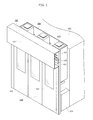
- FIG. 1 depicts a perspective view showing a transfer device as a whole.
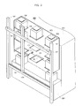
- FIG. 2 depicts a perspective view showing the transfer device without a cover.
- a transfer device 100 is provided in front of a device 200, such as a semiconductor manufacturing device, and a loader and unloader 201, and transfers an object 202 from one of shelf plates 301 to another one of the shelf plates 301.
- the shelf plates 301 are vertically and horizontally arranged, and provided to a shelf 300.
- the transfer device 100 includes pillars 101, an upper rail 102, a vertical rail 103, a lower rail 104, a holding unit 105, a cover 106, a horizontal driving unit 107, and a vertical driving unit 108.
- the pillars 101 vertically stand in front of the shelf 300.
- the pillars 101 are provided with their space therebetween slightly wider than the width of the device 200, and arranged so that a plane formed between the two pillars is placed in parallel with the front face of the device 200.
- the upper rail 102 is horizontally attached to the upper front-side faces of the two pillars 101 in order to tie the pillars 101 together.
- the upper rail 102 includes an endless belt used for horizontally driving the vertical rail 103.
- the vertical rail 103 is vertically provided in the plane including the two pillars 101 , and is slidably attached to a side face of the upper rail 102.
- the vertical rail 103 and the upper rail 102 are provided so that they overlap with each other in a front-back direction.
- the lower rail 104 is provided in a plane formed in phantom between the two pillars 101.
- the lower rail 104 is provided under the vertical rail 103, and sandwiched between the two pillars 101 to tie the pillars 101 together in a manner that both ends of the lower rail 104 abut lower parts of the two pillars 101.
- the lower rail 104 is attached to the vertical rail 103 in a manner which allows the vertical rail 103 to slide.
- the lower rail 104 and the vertical rail 103 are provided in the same plane, and the vertical rail 103 moves in the plane.
- the lower rail 104 and the vertical rail 103 are connected to each other via a pulley case 131.
- the pulley case 131 is fixed to the vertical rail 103.
- the pulley case 131 and the vertical rail 103 move together in a direction where the lower rail 104 extends.
- a bracket may be provided to connect the vertical rail 103 with the lower rail 104, bypassing the pulley case 131.
- the holding unit 105 detachably holds the object 202.
- the holding unit 105 projects from the vertical rail 103 to the shelf 300, and is slidably connected to a side face of the vertical rail 103.
- a flange 203 is provided on an upper part of the object 202 for holding the object 202.
- the holding unit 105 horizontally moves to hold and release the flange 203.
- the holding unit 105 includes a hook 151. When the flange is inserted into the hook 151, the hook catches the bottom face of the flange 203 and lifts the object 202.
- the horizontal driving unit 107 is attached to an end of the upper rail 102, and horizontally drives the vertical rail 103.
- the horizontal driving unit 107 drives the endless belt, included in the upper rail 102, in a forward direction and a backward direction.
- the vertical rail 103 attached to the endless belt horizontally moves, being guided by the upper rail 102 and the lower rail 104.
- the horizontal driving unit 107 is not attached to the lower rail 104. This is because the lower space in front of the transfer device 100 is to be kept wide. Hence, as far as the lower space is not affected, a small driving unit may be attached to the lower rail 104.
- the vertical driving unit 108 is attached to a side face at the upper end of the vertical rail 103, and vertically drives the holding unit 105.
- the vertical driving unit 108 drives an endless belt, attached to the vertical rail 103, in a forward direction and a backward direction.
- the holding unit 105 attached to the endless belt is guided by the vertical rail 103, and horizontally moves.
- the upper rail 102 is provided below the vertical driving unit 108.
- the vertical driving unit 108 moves together with the vertical rail 103, the vertical driving unit 108 and the upper rail 102 do not interfere with each other.
- the cover 106 is a wall-like member which separates the user and the transfer device 100 when the transfer device 100 is running.
- the cover 106 is provided in front of the two pillars 101 to cover the entire moving area of the holding unit 105.
- the cover 106 includes: an upper cover 161 which (i) projects forward to cover the upper rail 102 located in the upper moving area and (ii) extends along the upper rail 102; and a lower cover 163 which (i) is provided behind the upper cover 161 and (ii) covers the lower part of the lower part of the moving area.
- the lower cover 163 has three doors 162. The user opens the doors 162 to reach the transfer device 100 and the loader and unloader 201.
- the shelf 300 is provided above the loader and unloader 201, and temporarily stores an object 202 received from an overhead transferring vehicle and another object 202 to be transferred to an overhead transferring vehicle.
- the shelf 300 acts as a buffer for the objects 202 provided near a machine.
- the shelf 300 includes three columns of the shelf plates 301, and each column has three shelf plates 301 vertically arranged.
- the shelf 300 can store nine objects 202 in total.
- the shelf 300 includes an aisle vertically extending between the shelf plates 301. This structure allows the object 202 to be vertically moved in the shelf 300.
- a space is provided between the shelf 300 and the loader and unloader 201, so that the object 202 can be horizontally moved through the space.
- the shelf 300 allows the transfer device 100 to freely transfer the object 202 inside the shelf 300.
- the loader and unloader 201 is a device which brings to the device 200 a substrate contained in the object 202, and puts a processed substrate into the object 202 and carries out the object 202.
- the loader and unloader 201 also works as the shelf 300 for temporarily storing the object 202.
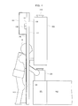
- FIG. 3 depicts a plan view showing the transfer device and the user from the side.
- the transfer device 100 described above has the upper rail 102 and the lower rail 104 horizontally provided. In addition to the high stiffness, the transfer device 100 has forward-projecting (on the left of FIG. 3 ) portions concentrated in its upper area. Such a structure allows the transfer device 100 to keep the space wide for a user H and a vehicle to travel. In other words, the transfer device 100 can keep the aisle width substantially wide.
- the vertical driving unit 108 is not provided above the pillars 101 , and does not interfere with the upper rail 102.
- This structure can keep a space wide over the transfer device 100. Hence, even though an overhead traveling vehicle is provided over the device 200, this structure successfully prevents interference of the transfer device 100 with the overhead traveling vehicle.
- FIG. 4 is a plan view showing from the side how the user opens a door and reaches an object.
- the transfer device 100 is out of service, and the user H opens the doors 162 on the cover 106 to reach an object 202 stored on the loader and unloader 201. Even in such a case, the user H is not bothered by the lower rail 104, and can easily reach the object 202. This is because the lower rail 104 is provided to a relatively lower part of the transfer device 100, and does not project forward of the pillars 101.
- the present invention shall not be limited to the above embodiment.
- the holding unit 105 may have a hook to be inserted into a lower part of the object 202 and to lift the object 202.
- the shelf 300 can store the objects 202 three high and three wide.
- the loader and unloader 201 according to the embodiment also stores the objects 202. Consequently, the loader and unloader 201 is a part of the shelf 300.
- loader and unloader describes a device which is capable of either (i) one of bringing in and carrying out an object or (ii) both bringing in and carrying out.
- the present invention is applicable to an automated shelf for a machine placed near a semiconductor manufacturing device.
Landscapes
- Engineering & Computer Science (AREA)
- Mechanical Engineering (AREA)
- Warehouses Or Storage Devices (AREA)
- Container, Conveyance, Adherence, Positioning, Of Wafer (AREA)
- Robotics (AREA)
Abstract
Description
- The present invention relates to a transfer device which is provided between a semiconductor manufacturing device and an aisle, and used for a shelf that temporarily stores an object containing a substrate necessary to manufacture a semiconductor and changes a storage area for the object within the shelf.
- When substrates such as a glass substrate and a silicon substrate are brought from another place to a semiconductor manufacturing device and when processed substrates are carried out to another place, a conventional scheme utilizes a box, referred to as container, to contain multiple substrates and transfers the container. In transferring the container, an overhead transferring vehicle which travels near the ceiling is used to save the space in a semiconductor manufacturing factory.
- The container has to be temporarily stored, depending how a preceding process and an after process progress in the manufacturing process of semiconductors. In order to store the container, a shelf for storing the container is provided above a loader and an unloader for the semiconductor manufacturing device. The semiconductor manufacturing device has a transfer device. The transfer device can automatically transfer an appropriate container from the shelf to the loader when the substrates are ready to be processed. The transfer device can also automatically transfer from the unloader to the shelf a container containing processed substrates.
- In order to save the space, a semiconductor manufacturing factory has semiconductor manufacturing devices on both sides of an aisle across from each other. The loader and the unloader are provided between the semiconductor manufacturing device and the aisle. The transfer device is provided between the loader/unloader and the aisle.
- Patent Literature 1 discloses a transfer device and a shelf. The shelf in Patent Literature 1 has horizontal and vertical aisles so that a container held by the transfer device can move inside the shelf. This structure saves as much space as possible. Moreover, the transfer device has rails each used for moving a holding unit, which holds a container, in the vertical direction and the horizontal direction. The rails are attached to the shelf. This structure provides as wide aisles as possible.
-
- [PTL 1] Japanese Unexamined Patent Application Publication No.
2001-298069 - As recent substrates are becoming larger, a container for containing the substrates is becoming heavier. Such a trend requires a transfer device to be stiffer.
- The present invention is conceived in view of the above problem and has an object to provide a transfer device which has enough stiffness and keeps an aisle wide around the footprint of the transfer device.
- In order to solve the above problem, a transfer device of the present invention transfers an object stored on one of shelf plates to an other one of the shelf plates, the shelf plates being arranged vertically and horizontally and provided to a shelf. The transfer device includes: two pillars which vertically stand in front of the shelf; an upper rail which is horizontally attached to upper front-side faces of the two pillars so as to tie the two pillars together; a vertical rail which is vertically and slidably connected to a side face of the upper rail; a lower rail which is provided under the vertical rail included in a plane, attached to lower parts of the two pillars, and connected to the vertical rail in a manner which allows the vertical rail to slide; and a holding unit which projects from the vertical rail to the shelf and is slidably connected to a side face of the vertical rail, and configured to detachably hold the object.
- This structure allows the upper rail and the lower rail to guide the vertical rail, which contributes to improving stiffness of the transfer device. This structure also makes it possible to disperse a load between the upper rail and the lower rail. Consequently, the upper rail can be made thinner to excessively avoid projecting to the aisle. Furthermore, the lower rail is provided in the same plane as the pillars are. This structure makes it possible to substantially reduce above-the-ground thickness, of the transfer device, which a user can feel when passing by. Consequently, this feature contributes to providing a wider aisle.
- Furthermore, the transfer device may include: a cover which is provided in front of the two pillars, and covers a moving area of the holding unit, wherein the cover includes: an upper cover which covers the upper rail; and a lower cover which is provided behind the upper cover, and covers a lower part of the moving area.
- The upper rail may include a horizontal driving unit configured to horizontally drive the vertical rail, and the lower rail may not include the horizontal driving unit.
- This structure makes it possible to employ a thin lower rail for the transfer device, which contributes to providing a wider aisle.
- The vertical rail may include a vertical driving unit which is attached to a side face at an upper end of the vertical rail, and vertically drives the holding unit, and the upper rail may be provided below the vertical driving unit.
- This structure makes it possible to keep a space wide over the transfer device, which contributes to easily preventing interference of the transfer device with the object held by the overhead traveling vehicle.
- The present invention successfully implements a highly-stiff transfer device which keeps an aisle wide.
-
- [
Fig. 1] FIG. 1 depicts a perspective view showing a transfer device as a whole. - [
Fig. 2] FIG. 2 depicts a perspective view showing the transfer device with a cover removed. - [
Fig. 3] FIG. 3 depicts a plan view showing the transfer device and a user from the side. - [
Fig. 4] FIG. 4 is a plan view showing from the side how the user opens a door and reaches an object. - Described hereinafter is an embodiment of the present invention with reference to the drawings.
-
FIG. 1 depicts a perspective view showing a transfer device as a whole. -
FIG. 2 depicts a perspective view showing the transfer device without a cover. - As shown in the drawings, a
transfer device 100 is provided in front of adevice 200, such as a semiconductor manufacturing device, and a loader andunloader 201, and transfers anobject 202 from one ofshelf plates 301 to another one of theshelf plates 301. Here, theshelf plates 301 are vertically and horizontally arranged, and provided to ashelf 300. Thetransfer device 100 includespillars 101, anupper rail 102, avertical rail 103, alower rail 104, aholding unit 105, acover 106, ahorizontal driving unit 107, and avertical driving unit 108. - The
pillars 101 vertically stand in front of theshelf 300. In the embodiment, thepillars 101 are provided with their space therebetween slightly wider than the width of thedevice 200, and arranged so that a plane formed between the two pillars is placed in parallel with the front face of thedevice 200. - The
upper rail 102 is horizontally attached to the upper front-side faces of the twopillars 101 in order to tie thepillars 101 together. In the embodiment, theupper rail 102 includes an endless belt used for horizontally driving thevertical rail 103. - The
vertical rail 103 is vertically provided in the plane including the twopillars 101 , and is slidably attached to a side face of the upper rail 102.Thevertical rail 103 and theupper rail 102 are provided so that they overlap with each other in a front-back direction. - The
lower rail 104 is provided in a plane formed in phantom between the twopillars 101. Thelower rail 104 is provided under thevertical rail 103, and sandwiched between the twopillars 101 to tie thepillars 101 together in a manner that both ends of thelower rail 104 abut lower parts of the twopillars 101. Moreover, thelower rail 104 is attached to thevertical rail 103 in a manner which allows thevertical rail 103 to slide. In other words, thelower rail 104 and thevertical rail 103 are provided in the same plane, and thevertical rail 103 moves in the plane. - In the embodiment, the
lower rail 104 and thevertical rail 103 are connected to each other via apulley case 131. Thepulley case 131 is fixed to thevertical rail 103. Thus, thepulley case 131 and thevertical rail 103 move together in a direction where thelower rail 104 extends. It is noted that in the case where thepulley case 131 is short of stiffness, a bracket may be provided to connect thevertical rail 103 with thelower rail 104, bypassing thepulley case 131. - The holding
unit 105 detachably holds theobject 202. The holdingunit 105 projects from thevertical rail 103 to theshelf 300, and is slidably connected to a side face of thevertical rail 103. - In the embodiment, a
flange 203 is provided on an upper part of theobject 202 for holding theobject 202. The holdingunit 105 horizontally moves to hold and release theflange 203. The holdingunit 105 includes ahook 151. When the flange is inserted into thehook 151, the hook catches the bottom face of theflange 203 and lifts theobject 202. - The
horizontal driving unit 107 is attached to an end of theupper rail 102, and horizontally drives thevertical rail 103. In the embodiment, thehorizontal driving unit 107 drives the endless belt, included in theupper rail 102, in a forward direction and a backward direction. Hence, thevertical rail 103 attached to the endless belt horizontally moves, being guided by theupper rail 102 and thelower rail 104. - It is noted that the
horizontal driving unit 107 is not attached to thelower rail 104. This is because the lower space in front of thetransfer device 100 is to be kept wide. Hence, as far as the lower space is not affected, a small driving unit may be attached to thelower rail 104. - The
vertical driving unit 108 is attached to a side face at the upper end of thevertical rail 103, and vertically drives the holdingunit 105. In the embodiment, similar to theupper rail 102, thevertical driving unit 108 drives an endless belt, attached to thevertical rail 103, in a forward direction and a backward direction. Hence, the holdingunit 105 attached to the endless belt is guided by thevertical rail 103, and horizontally moves. - In the embodiment, the
upper rail 102 is provided below thevertical driving unit 108. Thus, when thevertical driving unit 108 moves together with thevertical rail 103, thevertical driving unit 108 and theupper rail 102 do not interfere with each other. - The
cover 106 is a wall-like member which separates the user and thetransfer device 100 when thetransfer device 100 is running. Thecover 106 is provided in front of the twopillars 101 to cover the entire moving area of the holdingunit 105. Thecover 106 includes: anupper cover 161 which (i) projects forward to cover theupper rail 102 located in the upper moving area and (ii) extends along theupper rail 102; and alower cover 163 which (i) is provided behind theupper cover 161 and (ii) covers the lower part of the lower part of the moving area. In the embodiment, thelower cover 163 has threedoors 162. The user opens thedoors 162 to reach thetransfer device 100 and the loader andunloader 201. - The
shelf 300 is provided above the loader andunloader 201, and temporarily stores anobject 202 received from an overhead transferring vehicle and anotherobject 202 to be transferred to an overhead transferring vehicle. In other words, theshelf 300 acts as a buffer for theobjects 202 provided near a machine. In the embodiment, theshelf 300 includes three columns of theshelf plates 301, and each column has threeshelf plates 301 vertically arranged. Thus, theshelf 300 can store nineobjects 202 in total. Furthermore, theshelf 300 includes an aisle vertically extending between theshelf plates 301. This structure allows theobject 202 to be vertically moved in theshelf 300. - Furthermore, a space is provided between the
shelf 300 and the loader andunloader 201, so that theobject 202 can be horizontally moved through the space. Thus, theshelf 300 allows thetransfer device 100 to freely transfer theobject 202 inside theshelf 300. - The loader and
unloader 201 is a device which brings to the device 200 a substrate contained in theobject 202, and puts a processed substrate into theobject 202 and carries out theobject 202. In the embodiment, the loader andunloader 201 also works as theshelf 300 for temporarily storing theobject 202. -
FIG. 3 depicts a plan view showing the transfer device and the user from the side. - The
transfer device 100 described above has theupper rail 102 and thelower rail 104 horizontally provided. In addition to the high stiffness, thetransfer device 100 has forward-projecting (on the left ofFIG. 3 ) portions concentrated in its upper area. Such a structure allows thetransfer device 100 to keep the space wide for a user H and a vehicle to travel. In other words, thetransfer device 100 can keep the aisle width substantially wide. - Furthermore, the
vertical driving unit 108 is not provided above thepillars 101 , and does not interfere with theupper rail 102. This structure can keep a space wide over thetransfer device 100. Hence, even though an overhead traveling vehicle is provided over thedevice 200, this structure successfully prevents interference of thetransfer device 100 with the overhead traveling vehicle. -
FIG. 4 is a plan view showing from the side how the user opens a door and reaches an object. - As shown in
FIG. 4 , suppose the case where thetransfer device 100 is out of service, and the user H opens thedoors 162 on thecover 106 to reach anobject 202 stored on the loader andunloader 201. Even in such a case, the user H is not bothered by thelower rail 104, and can easily reach theobject 202. This is because thelower rail 104 is provided to a relatively lower part of thetransfer device 100, and does not project forward of thepillars 101. - It is noted that the present invention shall not be limited to the above embodiment. For example, instead of catching the
flange 203 provided on an upper part of theobject 202 and transferring theobject 202 with the object suspended, the holdingunit 105 may have a hook to be inserted into a lower part of theobject 202 and to lift theobject 202. Theshelf 300 can store theobjects 202 three high and three wide. The loader andunloader 201 according to the embodiment also stores theobjects 202. Consequently, the loader andunloader 201 is a part of theshelf 300. - Any given combination of the constitutional features described in the specification may be appreciated to implement an embodiment of the present invention other than the above described embodiment. Although only one exemplary embodiment of this invention has been described in detail above, those skilled in the art will readily appreciate that many modifications are possible in the exemplary embodiment without materially departing from the novel teachings and advantages of this invention. Accordingly, all such modifications are intended to be included within the scope of this invention.
- The words such as "vertical", "plane", and "parallel" are used within a margin of error without departing from the intents of the present invention. Moreover, the word "loader and unloader" describes a device which is capable of either (i) one of bringing in and carrying out an object or (ii) both bringing in and carrying out.
- The present invention is applicable to an automated shelf for a machine placed near a semiconductor manufacturing device.
-
- 100
- Transfer device
- 101
- Pillar
- 102
- Upper rail
- 103
- Vertical rail
- 104
- Lower rail
- 105
- Holding unit
- 106
- Cover
- 107
- Horizontal driving unit
- 108
- Vertical driving unit
- 131
- Pulley case
- 151
- Hook
- 161
- Upper cover
- 162
- Door
- 163
- Lower cover
- 200
- Device
- 201
- Loader and unloader
- 202
- Object
- 203
- Flange
- 300
- Shelf
- 301
- Shelf plate
Claims (4)
- A transfer device which transfers an object stored on one of shelf plates to an other one of the shelf plates, the shelf plates being arranged vertically and horizontally and provided to a shelf, and the transfer device comprising:two pillars which vertically stand in front of the shelf;an upper rail which is horizontally attached to upper front-side faces of the two pillars so as to tie the two pillars together;a vertical rail which is vertically and slidably connected to a side face of the upper rail;a lower rail which is provided under the vertical rail included in a plane, attached to lower parts of the two pillars, and connected to the vertical rail in a manner which allows the vertical rail to slide; anda holding unit which projects from the vertical rail to the shelf and is slidably connected to a side face of the vertical rail, and configured to detachably hold the object.
- The transfer device according to Claim 1 , further comprising
a cover which is provided in front of the two pillars, and covers a moving area of the holding unit,
wherein the cover includes:an upper cover which covers the upper rail; anda lower cover which is provided behind the upper cover,and covers a lower part of the moving area. - The transfer device according to Claim 1,
wherein the upper rail includes a horizontal driving unit configured to horizontally drive the vertical rail, and the lower rail does not include the horizontal driving unit. - The transfer device according to Claim 1,
wherein the vertical rail includes a vertical driving unit which is attached to a side face at an upper end of the vertical rail, and configured to vertically drive the holding unit, and
the upper rail is provided below the vertical driving unit.
Applications Claiming Priority (1)
| Application Number | Priority Date | Filing Date | Title |
|---|---|---|---|
| PCT/JP2010/003237 WO2011141966A1 (en) | 2010-05-13 | 2010-05-13 | Transfer device |
Publications (2)
| Publication Number | Publication Date |
|---|---|
| EP2571046A1 true EP2571046A1 (en) | 2013-03-20 |
| EP2571046A4 EP2571046A4 (en) | 2014-09-24 |
Family
ID=44914036
Family Applications (1)
| Application Number | Title | Priority Date | Filing Date |
|---|---|---|---|
| EP10851352.4A Withdrawn EP2571046A4 (en) | 2010-05-13 | 2010-05-13 | TRANSFER DEVICE |
Country Status (8)
| Country | Link |
|---|---|
| US (1) | US9056718B2 (en) |
| EP (1) | EP2571046A4 (en) |
| JP (1) | JP5365743B2 (en) |
| KR (1) | KR101416433B1 (en) |
| CN (1) | CN102893385B (en) |
| SG (1) | SG185538A1 (en) |
| TW (1) | TWI478269B (en) |
| WO (1) | WO2011141966A1 (en) |
Families Citing this family (6)
| Publication number | Priority date | Publication date | Assignee | Title |
|---|---|---|---|---|
| JP6414525B2 (en) * | 2015-09-02 | 2018-10-31 | 株式会社ダイフク | Storage facilities |
| JP6432488B2 (en) * | 2015-11-12 | 2018-12-05 | 株式会社ダイフク | Storehouse |
| CN106064716B (en) * | 2016-08-01 | 2018-06-15 | 厦门大学嘉庚学院 | Small-sized tiered warehouse facility power assisting device and application method |
| US10336541B2 (en) * | 2016-09-28 | 2019-07-02 | Hall Labs Llc | Automated storage and retrieval system with retractable mountings |
| US12441557B2 (en) * | 2021-12-30 | 2025-10-14 | Semes Co., Ltd. | Apparatus and method for transporting articles |
| JP7582232B2 (en) | 2022-03-03 | 2024-11-13 | 村田機械株式会社 | Storage device and storage method |
Family Cites Families (22)
| Publication number | Priority date | Publication date | Assignee | Title |
|---|---|---|---|---|
| JPH062527B2 (en) * | 1984-04-27 | 1994-01-12 | 株式会社東芝 | Transport system for clean room |
| JPH0114565Y2 (en) | 1984-11-22 | 1989-04-28 | ||
| US4846620A (en) * | 1986-12-29 | 1989-07-11 | Contact Systems, Inc. | Component assembly system |
| US5249904A (en) * | 1987-12-01 | 1993-10-05 | Tsubakimoto Chain Co. | Stock handling apparatus |
| JPH01145906A (en) | 1987-12-01 | 1989-06-07 | Tsubakimoto Chain Co | Accommodated object transferring and storing device |
| US4964776A (en) | 1987-12-01 | 1990-10-23 | Tsubakimoto Chain Co. | Article transfer and storage system |
| JPH01203106A (en) * | 1988-02-04 | 1989-08-15 | Ishikawajima Harima Heavy Ind Co Ltd | Rising/lowering device |
| US5064337A (en) | 1988-07-19 | 1991-11-12 | Tokyo Electron Limited | Handling apparatus for transferring carriers and a method of transferring carriers |
| US5468110A (en) * | 1990-01-24 | 1995-11-21 | Automated Healthcare, Inc. | Automated system for selecting packages from a storage area |
| JPH05338732A (en) | 1992-06-11 | 1993-12-21 | Kokusai Electric Co Ltd | Wafer cassette feeding / discharging device for vertical diffusion / CVD equipment |
| JPH0910082A (en) * | 1995-06-26 | 1997-01-14 | Kubota Corp | Vegetable and fruit sales equipment |
| JPH09223269A (en) * | 1995-12-14 | 1997-08-26 | Silk Hosei Kojo:Kk | Automatic vending device |
| JPH10172213A (en) | 1996-12-05 | 1998-06-26 | Sony Corp | Autochanger cassette transporter |
| US6079927A (en) * | 1998-04-22 | 2000-06-27 | Varian Semiconductor Equipment Associates, Inc. | Automated wafer buffer for use with wafer processing equipment |
| US6755322B1 (en) * | 2000-02-22 | 2004-06-29 | Hettie J. Herzog | Automated shopping system and apparatus |
| US6506009B1 (en) | 2000-03-16 | 2003-01-14 | Applied Materials, Inc. | Apparatus for storing and moving a cassette |
| US7695234B2 (en) * | 2001-12-04 | 2010-04-13 | Rorze Corporation | Device for temporarily loading, storing and unloading a container |
| US6655898B1 (en) * | 2001-12-11 | 2003-12-02 | Nec Electronics, Inc. | Front opening unified pod (FOUP) hoist jig |
| US20040081546A1 (en) * | 2002-08-31 | 2004-04-29 | Applied Materials, Inc. | Method and apparatus for supplying substrates to a processing tool |
| US7837058B2 (en) * | 2005-10-14 | 2010-11-23 | Crane Merchandising Systems, Inc. | Product transport system for a vending machine |
| US8757955B2 (en) | 2007-09-06 | 2014-06-24 | Murata Machinery, Ltd. | Storage, transporting system and storage set |
| CA2710782C (en) * | 2007-12-19 | 2016-10-04 | Safeaccess, Llc | Pharmaceutical storage and retrieval system and methods of storing and retrieving pharmaceuticals |
-
2010
- 2010-05-13 CN CN201080066678.XA patent/CN102893385B/en not_active Expired - Fee Related
- 2010-05-13 SG SG2012083374A patent/SG185538A1/en unknown
- 2010-05-13 JP JP2012514609A patent/JP5365743B2/en not_active Expired - Fee Related
- 2010-05-13 US US13/696,808 patent/US9056718B2/en not_active Expired - Fee Related
- 2010-05-13 WO PCT/JP2010/003237 patent/WO2011141966A1/en not_active Ceased
- 2010-05-13 EP EP10851352.4A patent/EP2571046A4/en not_active Withdrawn
- 2010-05-13 KR KR1020127029329A patent/KR101416433B1/en not_active Expired - Fee Related
-
2011
- 2011-04-22 TW TW100114009A patent/TWI478269B/en not_active IP Right Cessation
Also Published As
| Publication number | Publication date |
|---|---|
| TWI478269B (en) | 2015-03-21 |
| EP2571046A4 (en) | 2014-09-24 |
| US9056718B2 (en) | 2015-06-16 |
| WO2011141966A1 (en) | 2011-11-17 |
| JPWO2011141966A1 (en) | 2013-07-22 |
| US20130058742A1 (en) | 2013-03-07 |
| CN102893385A (en) | 2013-01-23 |
| TW201207982A (en) | 2012-02-16 |
| CN102893385B (en) | 2016-01-20 |
| KR20130016722A (en) | 2013-02-18 |
| JP5365743B2 (en) | 2013-12-11 |
| SG185538A1 (en) | 2012-12-28 |
| KR101416433B1 (en) | 2014-07-08 |
Similar Documents
| Publication | Publication Date | Title |
|---|---|---|
| JP5083278B2 (en) | Automatic warehouse in front of equipment | |
| KR102655164B1 (en) | Transport vehicles and transport equipment | |
| JP6327124B2 (en) | Goods transport vehicle | |
| EP2860136B1 (en) | Conveyance system and temporary storage method of articles in conveyance system | |
| US9056718B2 (en) | Transfer device | |
| TWI246501B (en) | Overhead traveling carriage system | |
| CN100584738C (en) | tower crane | |
| EP2957527B1 (en) | Transport facility and automated warehouse | |
| EP2835325B1 (en) | Conveyance system | |
| JP6512127B2 (en) | Article conveying apparatus and article conveying apparatus provided with the same | |
| KR20090026099A (en) | Warehouse, Return Systems, and Warehouse Sets | |
| JP2016011202A (en) | Automatic warehouse system | |
| CN101850883B (en) | Road vehicle system | |
| WO2006035473A1 (en) | Container carrying equipment | |
| EP2554495A1 (en) | Automated warehouse | |
| JP2008019017A (en) | Article storage device | |
| US20220161999A1 (en) | Transport vehicle system | |
| KR101000598B1 (en) | Rack apparatus for glass loading cassette used for thin glass tempered heat treatment device | |
| EP3015401A1 (en) | Automated warehouse and operation method for same | |
| US20050036857A1 (en) | Automatic material handling system and stocker therefor | |
| US20250289658A1 (en) | Transport Vehicle | |
| TWI483878B (en) | Automatic pre-installation warehouse | |
| KR20150125282A (en) | Carriage |
Legal Events
| Date | Code | Title | Description |
|---|---|---|---|
| PUAI | Public reference made under article 153(3) epc to a published international application that has entered the european phase |
Free format text: ORIGINAL CODE: 0009012 |
|
| 17P | Request for examination filed |
Effective date: 20121109 |
|
| AK | Designated contracting states |
Kind code of ref document: A1 Designated state(s): AL AT BE BG CH CY CZ DE DK EE ES FI FR GB GR HR HU IE IS IT LI LT LU LV MC MK MT NL NO PL PT RO SE SI SK SM TR |
|
| DAX | Request for extension of the european patent (deleted) | ||
| A4 | Supplementary search report drawn up and despatched |
Effective date: 20140827 |
|
| RIC1 | Information provided on ipc code assigned before grant |
Ipc: B65G 1/04 20060101ALI20140821BHEP Ipc: H01L 21/677 20060101AFI20140821BHEP |
|
| STAA | Information on the status of an ep patent application or granted ep patent |
Free format text: STATUS: THE APPLICATION HAS BEEN WITHDRAWN |
|
| 18W | Application withdrawn |
Effective date: 20180409 |