EP2571038A1 - Slide switch device - Google Patents
Slide switch device Download PDFInfo
- Publication number
- EP2571038A1 EP2571038A1 EP12182776A EP12182776A EP2571038A1 EP 2571038 A1 EP2571038 A1 EP 2571038A1 EP 12182776 A EP12182776 A EP 12182776A EP 12182776 A EP12182776 A EP 12182776A EP 2571038 A1 EP2571038 A1 EP 2571038A1
- Authority
- EP
- European Patent Office
- Prior art keywords
- slider
- tactile
- elastic
- feel
- cam
- Prior art date
- Legal status (The legal status is an assumption and is not a legal conclusion. Google has not performed a legal analysis and makes no representation as to the accuracy of the status listed.)
- Granted
Links
Images




Classifications
-
- H—ELECTRICITY
- H01—ELECTRIC ELEMENTS
- H01H—ELECTRIC SWITCHES; RELAYS; SELECTORS; EMERGENCY PROTECTIVE DEVICES
- H01H25/00—Switches with compound movement of handle or other operating part
- H01H25/002—Switches with compound movement of handle or other operating part having an operating member rectilinearly slidable in different directions
-
- H—ELECTRICITY
- H01—ELECTRIC ELEMENTS
- H01H—ELECTRIC SWITCHES; RELAYS; SELECTORS; EMERGENCY PROTECTIVE DEVICES
- H01H2300/00—Orthogonal indexing scheme relating to electric switches, relays, selectors or emergency protective devices covered by H01H
- H01H2300/008—Application power seats
Definitions
- the present invention relates to a slide switch device preferably used for a power seat switch etc. that electrically operates a lumber support embedded in a vehicle seat.
- the slide switch device including the tactile-feel generation mechanism
- a device of related art in which a tactile-feel adjustment tool is fitted and fixed to a guide base with a slider mounted, the slider has a shaft portion integrated with an operation knob, a coil spring and a ball are housed and held directly below the shaft portion, and the ball is pressed to a cam groove of the tactile-feel adjustment tool by an elastic force of the coil spring (for example, see Japanese Unexamined Patent Application Publication No. 2010-251028 ).
- the slider has a plurality of legs that engage with a driving portion of a switch element, and the legs pinch the tactile-feel adjustment tool in the thickness direction. Accordingly, if the operation knob is operated and the slider slides on the guide base, the ball slides in the cam groove of the tactile-feel adjustment tool and the tactile feel is generated, and rattling of the slider in the thickness direction of the tactile-feel adjustment tool is reduced.
- the slide switch device of the related art disclosed in Japanese Unexamined Patent Application Publication No. 2010-251028 reduces rattling of the slider in the thickness direction of the tactile-feel adjustment tool because the plurality of legs provided at the slider pinch the tactile-feel adjustment tool in the thickness direction.
- the pinching force of the legs is excessively strong, a sliding resistance between the legs and the tactile-feel adjustment tool excessively increases, and the slider cannot be operated to smoothly slide.
- the legs have to contact the tactile-feel adjustment tool by a relatively small pinching force. In this case, when the ball at an initial position is pressed to a valley portion of the cam groove, the slider can be held in a state with small rattling.
- the slider at the initial position is operated to slide and the ball is separated from the valley portion of the cam groove, the slider likely rattles in the sliding direction.
- the slider can be operated to slide in multiple directions including two directions being orthogonal to each other, rattling likely occurs during the sliding operation of the slider. An operation feel may markedly deteriorate.
- the present invention is made in the light of situations of the related art, and the present invention provides a slide switch device that restricts rattling of a slider and that provides a good operation feel.
- a slide switch device includes a switch element; a slider that performs a switching operation on a contact of the switch element, the slider having a shaft portion, a bottom surface, and corner portions; a guide base that movably supports the slider; a casing that pinches the slider between the casing and the guide base; an operation knob integrated with the shaft portion of the slider, the shaft portion protruding from the casing; and a tactile-feel generation portion having an elastic body interposed between the guide base and the slider, the tactile-feel generation portion generating a tactile feel when the slider is operated to slide via the operation knob.
- the slider includes an elastic urging portion that is deformed when the elastic urging portion is pressed to the guide base.
- the elastic urging portion and the tactile-feel generation portion are arranged by the same number at positions separated from the shaft portion.
- the slider when the slider is operated to slide in a desirable direction, the slider receives elastic forces from the elastic urging portion and the tactile-feel generation portion in a well balanced manner and the slider slides on the guide base. Accordingly, rattling of the slider can be restricted and an operation feel can be improved.
- the elastic urging portion may be preferably an elastic arm integrally formed with the slider in a cantilevered manner
- the tactile-feel generation portion may preferably include a cam portion formed at the bottom surface of the slider, a coil spring being the elastic body and held at the guide base, and a driving body that is elastically urged to the coil spring and is pressed to the cam portion. Accordingly, the elastic arm being the elastic urging portion and the cam portion being a component of the tactile-feel generation portion can be precisely integrally formed with the slider.
- two of the elastic arms may be preferably formed on one of the lines at equal distances from the intersection point, and two of the cam portions may be preferably formed on the other line at equal distances from the intersection point. Accordingly, the elastic arms and the cam portions can be arranged in a well balanced manner in the limited area of the slider.
- the slider may be preferably movable in two directions being orthogonal to each other, and also the two cam portions may be preferably formed in substantially conical recessed surfaces. Accordingly, the slider can be operated to slide smoothly in two different directions from the initial position.
- a multi-directional slide switch device with a good operation feel can be provided.
- the two elastic arms and the two cam portions may be preferably formed at the corner portions of the slider. Accordingly, rattling of the slider can be efficiently restricted.
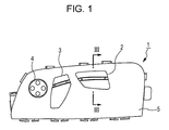
- a seat switch unit 1 shown in Fig. 1 operates a lumber support etc. embedded in a vehicle seat, and is arranged on a side of a sitting part of the vehicle seat.
- An operation knob 2 for adjusting a front-rear position, a height position, etc., of the seat; an operation knob 3 for reclining adjustment; and an operation knob 4 for adjusting a protruding amount of a hip portion of a backrest are arranged in line on the upper surface of the seat switch unit 1.
- a mechanism driven by the operation knob 2 is a slide switch device according to the embodiment of the present invention. In the following description, the slide switch device is described in detail, and description of switch devices driven by the other operation knobs 3 and 4 is omitted.
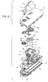
- the slide switch device mainly includes a casing 5 having a clearance hole 5a, the operation knob 2 arranged on an upper surface of the casing 5, a base body 6 that closes an opening at a lower surface of the casing 5, a circuit board 10 having a plurality of switch elements 7 to 9 etc. mounted thereon, a guide base 11 pinched between the casing 5 and the base body 6, a slider 12 pinched between the casing 5 and the guide base 11, a cam plate 13 engaging with a lower surface of the slider 12, a pair of driving bodies 14, and a pair of coil springs 15 etc.
- the casing 5 and the base body 6 are integrated by means for fixing such as screwing etc., and form an outer case.
- Components of the switch device except the operation knob 2 are housed in an inner space defined by the casing 5 and the base body 6.
- the circuit board 10 is fixed to an upper surface of the base body 6.
- other switch elements operated by the operation knobs 3 and 4 are mounted on the circuit board 10.
- the switch elements 7, 8, and 9 are known slide switches having stems 7a, 8a, and 9a protruding upward.
- embedded conductive plates move in a seesaw manner, to come into contact with and be separated from fixed contacts (see Fig. 3 ).
- the guide base 11 is a molded part made of synthetic resin having high smoothness.
- a restriction wall 11b is formed around a guide flat surface 11a having a substantially rectangular shape.
- the guide flat surface 11a has made therein three guide holes 11c, 11d, and 11e having track shapes.
- the longitudinal direction of the guide hole 11d being one of the three guide holes 11c, 11d, and 11e, is orthogonal to the longitudinal directions of the remaining two guide holes 11c and 11e.
- the guide flat surface 11a has made therein two holding holes 11f and 11g.
- the holding holes 11f and 11g have stepped shapes.
- the holding holes 11f and 11g respectively house the rod-shaped driving bodies 14 with the coil springs 15 interposed.
- the driving bodies 14 are urged to a lower surface of the slider 12 because the driving bodies 14 respectively receive elastic forces of the corresponding coil springs 15.
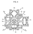
- the slider 12 is a molded part made of synthetic resin having good smoothness. As shown in Figs. 4 to 8 , the slider 12 includes a flat plate portion 12a extending in the horizontal direction, and a shaft portion 12b protruding upward from the flat plate portion 12a. The shaft portion 12b is inserted into the clearance hole 5a and protrudes to the upper side of the casing 5.
- the operation knob 2 is press-fitted to a distal end of the shaft portion 12b. Accordingly, the slider 12 and the operation knob 2 are integrated (see Fig. 3 ).
- Two elastic arms 12c and 12d and three through holes 12e, 12f, and 12g are formed at the flat plate portion 12a of the slider 12.
- Two cam portions 12h and 12i and a pair of guide rails 12j are formed at a back surface of the flat plate portion 12a.
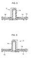
- the elastic arms 12c and 12d each are an elastic urging portion that is integrally formed with the flat plate portion 12a in a cantilevered manner. Distal ends (free ends) of the elastic arms 12c and 12d are pressed to the guide flat surface 11a of the guide base 11, so that the flat plate portion 12a of the slider 12 receives elastic forces from the elastic arms 12c and 12d and are urged to the lower surface of the casing 5. Also, the cam portions 12h and 12i are substantially conically recessed surfaces (dented surfaces) and the lower sides of the cam portions 12h and 12i are opened.
- a boundary portion between a valley portion formed at the center and a conical oblique surface of each of the cam portions 12h and 12i has a shape that generates the above-described tactile feel.
- the driving bodies 14 urged to the coil springs 15 are respectively pressed to the cam portions 12h and 12i.
- the flat plate portion 12a of the slider 12 is urged to the lower surface of the casing 5 while the flat plate portion 12a receives the elastic forces from the coil springs 15 in addition to the elastic forces from the elastic arms 12c and 12d.
- Two sets of tactile-feel generation portions are formed by the cam portions 12h and 12i, and the corresponding driving bodies 14 and coil springs 15.
- the elastic arms 12c and 12d are arranged on the line B, and the cam portions 12h and 12i are arranged on the line C.
- the lines B and C substantially orthogonally intersect with each other.
- Distal ends of the elastic arms 12c and 12d and the centers (the valley portions) of the cam portions 12h and 12i are alternately arranged at about 90 degrees on concentric circles around the shaft portion 12b.
- the cam plate 13 is formed by punching a metal flat seat into a predetermined shape.
- the cam plate 13 has a pair of guide grooves 13a at the center and three relief portions 13b at the periphery.
- the cam plate 13 is mounted on the guide flat surface 11a of the guide base 11.
- the guide rails 12j formed on the back surface of the flat plate portion 12a of the slider 12 respectively engage with the corresponding guide grooves 13a of the cam plate 13. Accordingly, only when the slider 12 is operated to slide in an extending direction of the guide grooves 13a, the slider 12 slides relative to the guide flat surface 11a and the cam plate 13.
- the slider 12 and the cam plate 13 slide together on the guide flat surface 11a. Even if the relative positions of the slider 12 and the cam plate 13 are changed, the cam plate 13 does not overlap the distal ends of the elastic arms 12c and 12d, or the centers of the cam portions 12h and 12i.
- the above-described stems 7a, 8a, and 9a of the switch elements 7, 8, and 9 are respectively inserted through the guide holes 11c, 11d, and 11e of the guide base 11 and the relief portions 13b of the cam plate 13, and then are respectively inserted into and engage with the corresponding through holes 12e, 12f, and 12g of the slider 12. Accordingly, when the slider 12 is operated to slide in X1-X2 directions in Fig. 9 , only the stem 7a engaging with the through hole 12e slides in the same direction accordingly, and performs a switching operation on the contact of the switch element 7. Also, when the slider 12 is operated to slide in Y1-Y2 directions in Fig.
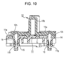
- the slide switch device As shown in Fig. 9 , when the slider 12 is at the initial position on the guide flat surface 11a of the guide base 11, the distal ends of the elastic arms 12c and 12d elastically contact the guide flat surface 11a, and the driving bodies 14 respectively receive the elastic forces from the coil springs 15 and are pressed to the valley portions of the cam portions 12h and 12i (see Fig. 10 ).
- the flat plate portion 12a of the slider 12 is elastically urged to the lower surface of the casing 5 in a well balanced manner and are held in a stable state by the elastic forces from the elastic arms 12c and 12d being the elastic urging portions, and the elastic forces from the coil springs 15 being the elastic bodies of the tactile-feel generation portions.
- the driving bodies 14 respectively climb over the valley portions of the corresponding cam portions 12h and 12i and are shifted to the conical oblique surfaces.
- the tactile feel generated at this time is fed back to the user who manually operates the operation knob 2.
- the stem 8a engaging with the through hole 12f is driven, and performs a switching operation on the contact of the switch element 8.
- the height position of the seat is adjusted in response to a contact switch signal of the switch element 8.
- the type and switch signal of the switch element 7, 8, or 9 driven in accordance with the sliding operation direction differs from the above described type and switch signal.
- the stem 8a is driven in a direction opposite to the above-described direction.
- the switch element 8 outputs another contact switch signal.
- the slider 12 slides relative to the guide flat surface 11a and the cam plate 13.
- the stem 7a engaging with the through hole 12e is driven, and performs a switching operation on the contact of the switch element 7.
- the front-rear position of the seat is adjusted in response to a contact switch signal of the switch element 7.
- the slider 12 is operated to rotate around the shaft portion 12b in the normal-reverse rotation directions by a predetermined angle
- the slider 12 and the cam plate 13 rotate together in the same direction on the guide flat surface 11a while sliding on the guide flat surface 11a.
- the stem 9a engaging with the through hole 12g is driven and performs a switching operation on the contact of the switch element 9.
- the orientation of the seat is adjusted in response to a contact switch signal of the switch element 9.
- the elastic urging portions (the elastic arms 12c and 12d) that are provided at the slider 12 and elastically contact the guide flat surface 11a of the guide base 11, and the tactile-feel generation portions (the cam portion 12h and 12i, the driving bodies 14, and the coil springs 15) that generate the tactile feel during the sliding operation of the slider 12 are provided by the same numbers at the positions separated from the shaft portion 12b of the slider 12. Accordingly, when the slider 12 is operated to slide in a desirable direction, the slider 12 slides on the guide flat surface 11a while the slider 12 receives the elastic forces from the elastic urging portions and the tactile-feel generation portions in a well balanced manner. Hence, rattling of the slider 12 is restricted and the operation feel can be improved.
- the elastic urging portions are formed of the elastic arms 12c and 12d that are integrally formed in a cantilevered manner with the flat plate portion 12a of the slider 12; and the tactile-feel generation portions are formed of the cam portions 12h and 12i formed at the back surface of the flat plate portion 12a of the slider 12, the coil springs (the elastic bodies) 15 held at the holding holes 11f and 11g of the guide base 11, and the driving bodies 14 that are elastically urged by the coil springs 15 and hence pressed to the cam portions 12h and 12i.
- the elastic urging portions (the elastic arms 12c and 12d) and part of the components of the tactile-feel generation portions (the cam portions 12h and 12i) can be precisely integrally formed with the slider 12 made of synthetic resin.
- the two elastic arms 12c and 12d are formed on one of the lines at equal distances from the intersection point O, and the two cam portions 12h and 12i are formed on the other line at equal distances from the intersection point O. Accordingly, the two elastic arms 12c and 12d and the two cam portions 12h and 12i can be arranged in a well balanced manner in the limited area of the slider 12. Also, the slider 12 moves in the two directions (the X and Y directions) being orthogonal to each other, and the two cam portions 12h and 12i are formed in conical shapes. Accordingly, the slider 12 can be operated to smoothly slide in the two different directions from the initial position. A multi-directional slide switch device with a good operation feel can be provided.
- the slide switch device in which the slider 12 can move in the two directions being orthogonal to each other (the X and Y directions) and in the rotation direction around the shaft portion 12b.
- the slide switch device in which the slider 12 can move only in the two directions being orthogonal to each other (the X and Y directions) or only in one of the X and Y directions may be provided.
- the cam plate 13 may be omitted.
- the cam portions 12h and 12i of the tactile-feel generation portions may be the substantially conical recessed surfaces (the dented surfaces).
- the shapes of the cam portions may be properly changed in accordance with the operation direction of the slider 12. For example, if the slider 12 can move only in the two directions being orthogonal to each other, the cam portion may be a dent with a cross-like shape in plan view.
- the cam portions 12h and 12i press the rod-shaped driving bodies 14. However, balls serving as the driving bodies may be pressed to the cam portions 12h and 12i.
Landscapes
- Slide Switches (AREA)
- Switches With Compound Operations (AREA)
Description
- The present invention relates to a slide switch device preferably used for a power seat switch etc. that electrically operates a lumber support embedded in a vehicle seat.
- With a slide switch device used for a power seat switch etc. of an automobile, when a user operates an operation knob of in a desirable direction, a slider that moves in association with the operation knob performs a switching operation on a contact of a switch element, and a tactile feel that is generated by a tactile-feel generation mechanism is fed back to the user. There has been known, as the slide switch device including the tactile-feel generation mechanism, a device of related art in which a tactile-feel adjustment tool is fitted and fixed to a guide base with a slider mounted, the slider has a shaft portion integrated with an operation knob, a coil spring and a ball are housed and held directly below the shaft portion, and the ball is pressed to a cam groove of the tactile-feel adjustment tool by an elastic force of the coil spring (for example, see Japanese Unexamined Patent Application Publication No.
2010-251028 - The slide switch device of the related art disclosed in Japanese Unexamined Patent Application Publication No.
2010-251028 - The present invention is made in the light of situations of the related art, and the present invention provides a slide switch device that restricts rattling of a slider and that provides a good operation feel.
- According to an aspect of the present invention, there is provided a slide switch device includes a switch element; a slider that performs a switching operation on a contact of the switch element, the slider having a shaft portion, a bottom surface, and corner portions; a guide base that movably supports the slider; a casing that pinches the slider between the casing and the guide base; an operation knob integrated with the shaft portion of the slider, the shaft portion protruding from the casing; and a tactile-feel generation portion having an elastic body interposed between the guide base and the slider, the tactile-feel generation portion generating a tactile feel when the slider is operated to slide via the operation knob. The slider includes an elastic urging portion that is deformed when the elastic urging portion is pressed to the guide base. The elastic urging portion and the tactile-feel generation portion are arranged by the same number at positions separated from the shaft portion.
- With the thus-configured slide switch device, when the slider is operated to slide in a desirable direction, the slider receives elastic forces from the elastic urging portion and the tactile-feel generation portion in a well balanced manner and the slider slides on the guide base. Accordingly, rattling of the slider can be restricted and an operation feel can be improved.
- In the above configuration, the elastic urging portion may be preferably an elastic arm integrally formed with the slider in a cantilevered manner, and the tactile-feel generation portion may preferably include a cam portion formed at the bottom surface of the slider, a coil spring being the elastic body and held at the guide base, and a driving body that is elastically urged to the coil spring and is pressed to the cam portion. Accordingly, the elastic arm being the elastic urging portion and the cam portion being a component of the tactile-feel generation portion can be precisely integrally formed with the slider.
- In this case, when two lines having an intersection point at the shaft portion are set in a plane extending in a moving direction of the slider, two of the elastic arms may be preferably formed on one of the lines at equal distances from the intersection point, and two of the cam portions may be preferably formed on the other line at equal distances from the intersection point. Accordingly, the elastic arms and the cam portions can be arranged in a well balanced manner in the limited area of the slider.
- Also, in this case, the slider may be preferably movable in two directions being orthogonal to each other, and also the two cam portions may be preferably formed in substantially conical recessed surfaces. Accordingly, the slider can be operated to slide smoothly in two different directions from the initial position. A multi-directional slide switch device with a good operation feel can be provided.
- Also, in the above-described configuration, the two elastic arms and the two cam portions may be preferably formed at the corner portions of the slider. Accordingly, rattling of the slider can be efficiently restricted.
-
-
Fig. 1 is plan view of a seat switch unit on which a slide switch device according to an embodiment of the present invention is mounted; -
Fig. 2 is an exploded perspective view of the seat switch unit; -
Fig. 3 is a cross-sectional view taken along line III-III inFig. 1 ; -
Fig. 4 is a plan view of a slider provided at the slide switch device inFig. 1 ; -
Fig. 5 is a cross-sectional view taken along line V-V inFig. 4 ; -
Fig. 6 is a cross-sectional view taken along line VI-VI inFig. 4 ; -
Fig. 7 is a perspective view when viewed from an upper surface of the slider; -
Fig. 8 is a perspective view when viewed from a lower surface of the slider; -
Fig. 9 is a plan view showing a state in which the slider is at an initial position on a guide base; -
Fig. 10 is a cross-sectional view taken along line X-X inFig. 9 ; -
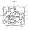
Fig. 11 is a plan view showing a state in which the slider is operated to slide on the guide base; and -
Fig. 12 is a cross-sectional view taken along line XII-XII inFig. 11 . - An embodiment of the present invention is described with reference to the drawings. A
seat switch unit 1 shown inFig. 1 operates a lumber support etc. embedded in a vehicle seat, and is arranged on a side of a sitting part of the vehicle seat. Anoperation knob 2 for adjusting a front-rear position, a height position, etc., of the seat; anoperation knob 3 for reclining adjustment; and anoperation knob 4 for adjusting a protruding amount of a hip portion of a backrest are arranged in line on the upper surface of theseat switch unit 1. A mechanism driven by theoperation knob 2 is a slide switch device according to the embodiment of the present invention. In the following description, the slide switch device is described in detail, and description of switch devices driven by theother operation knobs - As shown in
Fig. 2 , the slide switch device according to this embodiment mainly includes acasing 5 having aclearance hole 5a, theoperation knob 2 arranged on an upper surface of thecasing 5, abase body 6 that closes an opening at a lower surface of thecasing 5, acircuit board 10 having a plurality ofswitch elements 7 to 9 etc. mounted thereon, aguide base 11 pinched between thecasing 5 and thebase body 6, aslider 12 pinched between thecasing 5 and theguide base 11, acam plate 13 engaging with a lower surface of theslider 12, a pair ofdriving bodies 14, and a pair ofcoil springs 15 etc. - The
casing 5 and thebase body 6 are integrated by means for fixing such as screwing etc., and form an outer case. Components of the switch device except theoperation knob 2 are housed in an inner space defined by thecasing 5 and thebase body 6. - The
circuit board 10 is fixed to an upper surface of thebase body 6. In addition to the threeswitch elements 7 to 9 operated by theoperation knob 2, other switch elements operated by theoperation knobs circuit board 10. Theswitch elements switches having stems stems stems Fig. 3 ). - The
guide base 11 is a molded part made of synthetic resin having high smoothness. As shown inFig. 2 , arestriction wall 11b is formed around a guideflat surface 11a having a substantially rectangular shape. The guideflat surface 11a has made therein threeguide holes guide hole 11d, being one of the threeguide holes guide holes flat surface 11a has made therein twoholding holes Figs. 10 and12 , theholding holes holding holes shaped driving bodies 14 with thecoil springs 15 interposed. The drivingbodies 14 are urged to a lower surface of theslider 12 because the drivingbodies 14 respectively receive elastic forces of the corresponding coil springs 15. - The
slider 12 is a molded part made of synthetic resin having good smoothness. As shown inFigs. 4 to 8 , theslider 12 includes aflat plate portion 12a extending in the horizontal direction, and ashaft portion 12b protruding upward from theflat plate portion 12a. Theshaft portion 12b is inserted into theclearance hole 5a and protrudes to the upper side of thecasing 5. Theoperation knob 2 is press-fitted to a distal end of theshaft portion 12b. Accordingly, theslider 12 and theoperation knob 2 are integrated (seeFig. 3 ). Twoelastic arms holes flat plate portion 12a of theslider 12. Twocam portions flat plate portion 12a. - As shown in
Fig. 5 , theelastic arms flat plate portion 12a in a cantilevered manner. Distal ends (free ends) of theelastic arms flat surface 11a of theguide base 11, so that theflat plate portion 12a of theslider 12 receives elastic forces from theelastic arms casing 5. Also, thecam portions cam portions cam portions bodies 14 urged to the coil springs 15 are respectively pressed to thecam portions flat plate portion 12a of theslider 12 is urged to the lower surface of thecasing 5 while theflat plate portion 12a receives the elastic forces from the coil springs 15 in addition to the elastic forces from theelastic arms cam portions bodies 14 and coil springs 15. Although the detail is described later, when theslider 12 is operated to slide in a desirable direction, a tactile feel (a click feel) is generated from each of the tactile-feel generation portions. - As shown in
Fig. 4 , assuming that two lines B and C passing through the center O of theshaft portion 12b of theslider 12 and intersecting with each other are set, theelastic arms cam portions elastic arms cam portions shaft portion 12b. - The
cam plate 13 is formed by punching a metal flat seat into a predetermined shape. Thecam plate 13 has a pair ofguide grooves 13a at the center and threerelief portions 13b at the periphery. Thecam plate 13 is mounted on the guideflat surface 11a of theguide base 11. The guide rails 12j formed on the back surface of theflat plate portion 12a of theslider 12 respectively engage with thecorresponding guide grooves 13a of thecam plate 13. Accordingly, only when theslider 12 is operated to slide in an extending direction of theguide grooves 13a, theslider 12 slides relative to the guideflat surface 11a and thecam plate 13. When theslider 12 is operated to slide in other direction, theslider 12 and thecam plate 13 slide together on the guideflat surface 11a. Even if the relative positions of theslider 12 and thecam plate 13 are changed, thecam plate 13 does not overlap the distal ends of theelastic arms cam portions - The above-described stems 7a, 8a, and 9a of the
switch elements guide base 11 and therelief portions 13b of thecam plate 13, and then are respectively inserted into and engage with the corresponding throughholes slider 12. Accordingly, when theslider 12 is operated to slide in X1-X2 directions inFig. 9 , only thestem 7a engaging with the throughhole 12e slides in the same direction accordingly, and performs a switching operation on the contact of theswitch element 7. Also, when theslider 12 is operated to slide in Y1-Y2 directions inFig. 9 , only thestem 8a engaging with the throughhole 12f slides in the same direction accordingly, and in this case, performs a switching operation on the contact of theswitch element 8. Further, when theslider 12 is operated to rotate around theshaft portion 12b in normal-reverse rotation directions by a predetermined angle, only thestem 9a engaging with the throughhole 12g slides in the same direction accordingly, and in this case, performs a switching operation on the contact of theswitch element 9. - With the thus-configured slide switch device, as shown in
Fig. 9 , when theslider 12 is at the initial position on the guideflat surface 11a of theguide base 11, the distal ends of theelastic arms flat surface 11a, and the drivingbodies 14 respectively receive the elastic forces from the coil springs 15 and are pressed to the valley portions of thecam portions Fig. 10 ). Hence, theflat plate portion 12a of theslider 12 is elastically urged to the lower surface of thecasing 5 in a well balanced manner and are held in a stable state by the elastic forces from theelastic arms - In this state, if the user operates the
slider 12 via theoperation knob 2 in a desirable direction, for example, in the Y1 direction inFig. 9 , theslider 12 and thecam plate 13 slide together on the guideflat surface 11a in the same direction. Then, as shown inFig. 11 , the movement of theslider 12 in the same direction is restricted at a position at which an outer edge of theflat plate portion 12a contacts therestriction wall 11b of theguide base 11. Meanwhile, since theslider 12 slides on the guideflat surface 11a while theslider 12 receives the elastic forces from theelastic arms slider 12 is restricted, and a good operation feel can be obtained. Also, when theslider 12 slides from the initial position in a desirable direction in this way, as shown inFig. 12 , the drivingbodies 14 respectively climb over the valley portions of the correspondingcam portions operation knob 2. When theslider 12 slides in the Y1 direction, thestem 8a engaging with the throughhole 12f is driven, and performs a switching operation on the contact of theswitch element 8. Hence, for example, the height position of the seat is adjusted in response to a contact switch signal of theswitch element 8. - When the
slider 12 is operated to slide in a direction other than the Y1 direction inFig. 9 , the type and switch signal of theswitch element slider 12 is operated to slide in the Y2 direction inFig. 9 , thestem 8a is driven in a direction opposite to the above-described direction. In this case, theswitch element 8 outputs another contact switch signal. Also, when theslider 12 is operated to slide in the X1-X2 directions inFig. 9 , theslider 12 slides relative to the guideflat surface 11a and thecam plate 13. In this case, thestem 7a engaging with the throughhole 12e is driven, and performs a switching operation on the contact of theswitch element 7. Hence, for example, the front-rear position of the seat is adjusted in response to a contact switch signal of theswitch element 7. Further, when theslider 12 is operated to rotate around theshaft portion 12b in the normal-reverse rotation directions by a predetermined angle, theslider 12 and thecam plate 13 rotate together in the same direction on the guideflat surface 11a while sliding on the guideflat surface 11a. In this case, thestem 9a engaging with the throughhole 12g is driven and performs a switching operation on the contact of theswitch element 9. Hence, for example, the orientation of the seat is adjusted in response to a contact switch signal of theswitch element 9. Even in any of these cases, since theslider 12 slides on the guideflat surface 11a while theslider 12 receives the elastic forces from theelastic arms slider 12 is restricted, and a good operation feel can be obtained. - As described above, with the slide switch device according to this exemplary embodiment, the elastic urging portions (the
elastic arms slider 12 and elastically contact the guideflat surface 11a of theguide base 11, and the tactile-feel generation portions (thecam portion bodies 14, and the coil springs 15) that generate the tactile feel during the sliding operation of theslider 12 are provided by the same numbers at the positions separated from theshaft portion 12b of theslider 12. Accordingly, when theslider 12 is operated to slide in a desirable direction, theslider 12 slides on the guideflat surface 11a while theslider 12 receives the elastic forces from the elastic urging portions and the tactile-feel generation portions in a well balanced manner. Hence, rattling of theslider 12 is restricted and the operation feel can be improved. - The elastic urging portions are formed of the
elastic arms flat plate portion 12a of theslider 12; and the tactile-feel generation portions are formed of thecam portions flat plate portion 12a of theslider 12, the coil springs (the elastic bodies) 15 held at the holdingholes guide base 11, and the drivingbodies 14 that are elastically urged by the coil springs 15 and hence pressed to thecam portions elastic arms cam portions slider 12 made of synthetic resin. - Then, when the two lines intersecting with each other at the intersection point O that is the
shaft portion 12b are set in the plane extending along the moving directions of theslider 12, the twoelastic arms cam portions elastic arms cam portions slider 12. Also, theslider 12 moves in the two directions (the X and Y directions) being orthogonal to each other, and the twocam portions slider 12 can be operated to smoothly slide in the two different directions from the initial position. A multi-directional slide switch device with a good operation feel can be provided. - Described in the above-described embodiment is the slide switch device in which the
slider 12 can move in the two directions being orthogonal to each other (the X and Y directions) and in the rotation direction around theshaft portion 12b. However, the slide switch device in which theslider 12 can move only in the two directions being orthogonal to each other (the X and Y directions) or only in one of the X and Y directions may be provided. In this case, thecam plate 13 may be omitted. - Also, in the above-described embodiment, the
cam portions slider 12. For example, if theslider 12 can move only in the two directions being orthogonal to each other, the cam portion may be a dent with a cross-like shape in plan view. Also, thecam portions driving bodies 14. However, balls serving as the driving bodies may be pressed to thecam portions
Claims (5)
- A slide switch device, comprising:a switch element (7, 8);a slider (12) that performs a switching operation on a contact of the switch element (7, 8), the slider (12) having a shaft portion (12b), a bottom surface, and corner portions;a guide base (11) that movably supports the slider (12);a casing (5) that pinches the slider (12) between the casing (5) and the guide base (11);an operation knob (2) integrated with the shaft portion (12b) of the slider (12), the shaft portion (12b) protruding from the casing (5); anda tactile-feel generation portion having an elastic body (15) interposed between the guide base (11) and the slider (12), the tactile-feel generation portion generating a tactile feel when the slider (12) is operated to slide via the operation knob (2),wherein the slider (12) includes an elastic urging portion (12c, 12d) that is deformed when the elastic urging portion (12c, 12d) is pressed to the guide base (11), andwherein the elastic urging portion (12c, 12d) and the tactile-feel generation portion are arranged by the same number at positions separated from the shaft portion (12b).
- The slide switch device according to claim 1,
wherein the elastic urging portion (12c, 12d) is an elastic arm (12c, 12d) integrally formed with the slider (12) in a cantilevered manner, and
wherein the tactile-feel generation portion includesa cam portion (12h, 12i) formed at the bottom surface of the slider (12),a coil spring (15) being the elastic body (15) and held at the guide base (11), anda driving body (14) that is elastically urged to the coil spring (15) and is pressed to the cam portion (12h, 12i). - The slide switch device according to claim 2, wherein when two lines having an intersection point at the shaft portion (12b) are set in a plane extending in a moving direction of the slider (12), two of the elastic arms (12c, 12d) are formed on one of the lines at equal distances from the intersection point, and two of the cam portions (12h, 12i) are formed on the other line at equal distances from the intersection point.
- The slide switch device according to claim 3,
wherein the slider (12) is movable in two directions being orthogonal to each other, and
wherein the two cam portions (12h, 12i) are formed in substantially conical recessed surfaces. - The slide switch device according to claim 3 or 4, wherein the two elastic arms (12c, 12d) and the two cam portions (12h, 12i) are formed at the corner portions of the slider (12).
Applications Claiming Priority (1)
| Application Number | Priority Date | Filing Date | Title |
|---|---|---|---|
| JP2011203157A JP5941642B2 (en) | 2011-09-16 | 2011-09-16 | Slide switch device |
Publications (2)
| Publication Number | Publication Date |
|---|---|
| EP2571038A1 true EP2571038A1 (en) | 2013-03-20 |
| EP2571038B1 EP2571038B1 (en) | 2014-04-02 |
Family
ID=46982441
Family Applications (1)
| Application Number | Title | Priority Date | Filing Date |
|---|---|---|---|
| EP20120182776 Active EP2571038B1 (en) | 2011-09-16 | 2012-09-03 | Slide switch device |
Country Status (4)
| Country | Link |
|---|---|
| US (1) | US8952281B2 (en) |
| EP (1) | EP2571038B1 (en) |
| JP (1) | JP5941642B2 (en) |
| CN (1) | CN103000426B (en) |
Families Citing this family (2)
| Publication number | Priority date | Publication date | Assignee | Title |
|---|---|---|---|---|
| WO2017172630A1 (en) * | 2016-03-30 | 2017-10-05 | Shanghai Yanfeng Jinqiao Automotive Trim Systems Co. Ltd | Mechanism for console assembly |
| WO2025119492A1 (en) * | 2023-12-08 | 2025-06-12 | Merit Automotive Electronics Systems S.L.U. | Haptic switch assembly |
Citations (3)
| Publication number | Priority date | Publication date | Assignee | Title |
|---|---|---|---|---|
| EP0530509A2 (en) * | 1991-07-31 | 1993-03-10 | Omron Corporation | Switch device |
| US20090223798A1 (en) * | 2008-03-10 | 2009-09-10 | Toshitaka Miwa | Slide operation type electrical component |
| US20100258424A1 (en) * | 2009-04-13 | 2010-10-14 | Toyota Boshoku Kabushiki Kaisha | Slide switch structure and power seat switch using the same |
Family Cites Families (3)
| Publication number | Priority date | Publication date | Assignee | Title |
|---|---|---|---|---|
| US4454391A (en) * | 1982-09-29 | 1984-06-12 | Amp Incorporated | Low profile DIP switch |
| JPH034623U (en) * | 1989-06-07 | 1991-01-17 | ||
| CN103140907B (en) * | 2009-12-17 | 2015-09-16 | 欧姆龙多尔泰汽车电子有限公司 | Electric seat switch assembly |
-
2011
- 2011-09-16 JP JP2011203157A patent/JP5941642B2/en active Active
-
2012
- 2012-09-03 EP EP20120182776 patent/EP2571038B1/en active Active
- 2012-09-12 US US13/611,716 patent/US8952281B2/en active Active
- 2012-09-13 CN CN201210339525.9A patent/CN103000426B/en active Active
Patent Citations (4)
| Publication number | Priority date | Publication date | Assignee | Title |
|---|---|---|---|---|
| EP0530509A2 (en) * | 1991-07-31 | 1993-03-10 | Omron Corporation | Switch device |
| US20090223798A1 (en) * | 2008-03-10 | 2009-09-10 | Toshitaka Miwa | Slide operation type electrical component |
| US20100258424A1 (en) * | 2009-04-13 | 2010-10-14 | Toyota Boshoku Kabushiki Kaisha | Slide switch structure and power seat switch using the same |
| JP2010251028A (en) | 2009-04-13 | 2010-11-04 | Toyota Boshoku Corp | Slide switch structure and power seat switch using the same |
Also Published As
| Publication number | Publication date |
|---|---|
| US20130068598A1 (en) | 2013-03-21 |
| JP2013065447A (en) | 2013-04-11 |
| US8952281B2 (en) | 2015-02-10 |
| CN103000426A (en) | 2013-03-27 |
| JP5941642B2 (en) | 2016-06-29 |
| EP2571038B1 (en) | 2014-04-02 |
| CN103000426B (en) | 2015-06-03 |
Similar Documents
| Publication | Publication Date | Title |
|---|---|---|
| US6362810B1 (en) | Tiltable joystick pointing device | |
| US10930451B2 (en) | Keyswitch with adjustable tactile feedback | |
| US11037744B2 (en) | Switch device | |
| JPH0212718A (en) | push button switch | |
| EP2571038B1 (en) | Slide switch device | |
| CN103140907B (en) | Electric seat switch assembly | |
| KR20020071462A (en) | Multi-directional switching apparatus | |
| CN214588559U (en) | Switch assembly, automobile information entertainment system and vehicle | |
| US6262379B1 (en) | Switch apparatus | |
| US6545238B2 (en) | Key device with a scissors mechanism | |
| CN109920679B (en) | Non-contact type shaft of key and key | |
| JP3406800B2 (en) | Control switch | |
| CN209526708U (en) | A kind of light guide Non-contact key switch | |
| CN221202344U (en) | SMA touch actuator | |
| JP2004335298A (en) | Operation switch | |
| CN220585109U (en) | Rebound key structure | |
| JP6071727B2 (en) | Seesaw switch device | |
| JP3352680B2 (en) | Key switch device | |
| JP2000285765A (en) | Slide switch with center push mechanism | |
| JP2013225390A (en) | Seesaw switch device | |
| JP2001325857A (en) | Multi-directional input device | |
| JP3352678B2 (en) | Key switch device | |
| JP3352677B2 (en) | Key switch device | |
| CN114834369A (en) | Control switch for vehicle | |
| JP2010165513A (en) | Pressing key top structure |
Legal Events
| Date | Code | Title | Description |
|---|---|---|---|
| PUAI | Public reference made under article 153(3) epc to a published international application that has entered the european phase |
Free format text: ORIGINAL CODE: 0009012 |
|
| AK | Designated contracting states |
Kind code of ref document: A1 Designated state(s): AL AT BE BG CH CY CZ DE DK EE ES FI FR GB GR HR HU IE IS IT LI LT LU LV MC MK MT NL NO PL PT RO RS SE SI SK SM TR |
|
| AX | Request for extension of the european patent |
Extension state: BA ME |
|
| 17P | Request for examination filed |
Effective date: 20130830 |
|
| RBV | Designated contracting states (corrected) |
Designated state(s): AL AT BE BG CH CY CZ DE DK EE ES FI FR GB GR HR HU IE IS IT LI LT LU LV MC MK MT NL NO PL PT RO RS SE SI SK SM TR |
|
| GRAP | Despatch of communication of intention to grant a patent |
Free format text: ORIGINAL CODE: EPIDOSNIGR1 |
|
| RIC1 | Information provided on ipc code assigned before grant |
Ipc: H01H 25/00 20060101AFI20130930BHEP |
|
| INTG | Intention to grant announced |
Effective date: 20131023 |
|
| GRAS | Grant fee paid |
Free format text: ORIGINAL CODE: EPIDOSNIGR3 |
|
| GRAA | (expected) grant |
Free format text: ORIGINAL CODE: 0009210 |
|
| AK | Designated contracting states |
Kind code of ref document: B1 Designated state(s): AL AT BE BG CH CY CZ DE DK EE ES FI FR GB GR HR HU IE IS IT LI LT LU LV MC MK MT NL NO PL PT RO RS SE SI SK SM TR |
|
| REG | Reference to a national code |
Ref country code: GB Ref legal event code: FG4D |
|
| REG | Reference to a national code |
Ref country code: CH Ref legal event code: EP Ref country code: AT Ref legal event code: REF Ref document number: 660561 Country of ref document: AT Kind code of ref document: T Effective date: 20140415 |
|
| REG | Reference to a national code |
Ref country code: IE Ref legal event code: FG4D |
|
| REG | Reference to a national code |
Ref country code: DE Ref legal event code: R096 Ref document number: 602012001286 Country of ref document: DE Effective date: 20140515 |
|
| RAP2 | Party data changed (patent owner data changed or rights of a patent transferred) |
Owner name: BAYERISCHE MOTOREN WERKE AKTIENGESELLSCHAFT |
|
| REG | Reference to a national code |
Ref country code: AT Ref legal event code: MK05 Ref document number: 660561 Country of ref document: AT Kind code of ref document: T Effective date: 20140402 |
|
| REG | Reference to a national code |
Ref country code: NL Ref legal event code: VDEP Effective date: 20140402 |
|
| REG | Reference to a national code |
Ref country code: LT Ref legal event code: MG4D |
|
| PG25 | Lapsed in a contracting state [announced via postgrant information from national office to epo] |
Ref country code: NL Free format text: LAPSE BECAUSE OF FAILURE TO SUBMIT A TRANSLATION OF THE DESCRIPTION OR TO PAY THE FEE WITHIN THE PRESCRIBED TIME-LIMIT Effective date: 20140402 Ref country code: LT Free format text: LAPSE BECAUSE OF FAILURE TO SUBMIT A TRANSLATION OF THE DESCRIPTION OR TO PAY THE FEE WITHIN THE PRESCRIBED TIME-LIMIT Effective date: 20140402 Ref country code: IS Free format text: LAPSE BECAUSE OF FAILURE TO SUBMIT A TRANSLATION OF THE DESCRIPTION OR TO PAY THE FEE WITHIN THE PRESCRIBED TIME-LIMIT Effective date: 20140802 Ref country code: CY Free format text: LAPSE BECAUSE OF FAILURE TO SUBMIT A TRANSLATION OF THE DESCRIPTION OR TO PAY THE FEE WITHIN THE PRESCRIBED TIME-LIMIT Effective date: 20140402 Ref country code: CZ Free format text: LAPSE BECAUSE OF FAILURE TO SUBMIT A TRANSLATION OF THE DESCRIPTION OR TO PAY THE FEE WITHIN THE PRESCRIBED TIME-LIMIT Effective date: 20140402 Ref country code: GR Free format text: LAPSE BECAUSE OF FAILURE TO SUBMIT A TRANSLATION OF THE DESCRIPTION OR TO PAY THE FEE WITHIN THE PRESCRIBED TIME-LIMIT Effective date: 20140703 Ref country code: NO Free format text: LAPSE BECAUSE OF FAILURE TO SUBMIT A TRANSLATION OF THE DESCRIPTION OR TO PAY THE FEE WITHIN THE PRESCRIBED TIME-LIMIT Effective date: 20140702 Ref country code: BG Free format text: LAPSE BECAUSE OF FAILURE TO SUBMIT A TRANSLATION OF THE DESCRIPTION OR TO PAY THE FEE WITHIN THE PRESCRIBED TIME-LIMIT Effective date: 20140702 Ref country code: FI Free format text: LAPSE BECAUSE OF FAILURE TO SUBMIT A TRANSLATION OF THE DESCRIPTION OR TO PAY THE FEE WITHIN THE PRESCRIBED TIME-LIMIT Effective date: 20140402 |
|
| PG25 | Lapsed in a contracting state [announced via postgrant information from national office to epo] |
Ref country code: HR Free format text: LAPSE BECAUSE OF FAILURE TO SUBMIT A TRANSLATION OF THE DESCRIPTION OR TO PAY THE FEE WITHIN THE PRESCRIBED TIME-LIMIT Effective date: 20140402 Ref country code: AT Free format text: LAPSE BECAUSE OF FAILURE TO SUBMIT A TRANSLATION OF THE DESCRIPTION OR TO PAY THE FEE WITHIN THE PRESCRIBED TIME-LIMIT Effective date: 20140402 Ref country code: ES Free format text: LAPSE BECAUSE OF FAILURE TO SUBMIT A TRANSLATION OF THE DESCRIPTION OR TO PAY THE FEE WITHIN THE PRESCRIBED TIME-LIMIT Effective date: 20140402 Ref country code: LV Free format text: LAPSE BECAUSE OF FAILURE TO SUBMIT A TRANSLATION OF THE DESCRIPTION OR TO PAY THE FEE WITHIN THE PRESCRIBED TIME-LIMIT Effective date: 20140402 Ref country code: PL Free format text: LAPSE BECAUSE OF FAILURE TO SUBMIT A TRANSLATION OF THE DESCRIPTION OR TO PAY THE FEE WITHIN THE PRESCRIBED TIME-LIMIT Effective date: 20140402 Ref country code: RS Free format text: LAPSE BECAUSE OF FAILURE TO SUBMIT A TRANSLATION OF THE DESCRIPTION OR TO PAY THE FEE WITHIN THE PRESCRIBED TIME-LIMIT Effective date: 20140402 Ref country code: SE Free format text: LAPSE BECAUSE OF FAILURE TO SUBMIT A TRANSLATION OF THE DESCRIPTION OR TO PAY THE FEE WITHIN THE PRESCRIBED TIME-LIMIT Effective date: 20140402 |
|
| PG25 | Lapsed in a contracting state [announced via postgrant information from national office to epo] |
Ref country code: PT Free format text: LAPSE BECAUSE OF FAILURE TO SUBMIT A TRANSLATION OF THE DESCRIPTION OR TO PAY THE FEE WITHIN THE PRESCRIBED TIME-LIMIT Effective date: 20140804 |
|
| REG | Reference to a national code |
Ref country code: DE Ref legal event code: R097 Ref document number: 602012001286 Country of ref document: DE |
|
| REG | Reference to a national code |
Ref country code: DE Ref legal event code: R081 Ref document number: 602012001286 Country of ref document: DE Owner name: BAYERISCHE MOTOREN WERKE AKTIENGESELLSCHAFT, DE Free format text: FORMER OWNER: ALPS ELECTRIC CO., LTD, TOKYO, JP Effective date: 20141216 |
|
| PG25 | Lapsed in a contracting state [announced via postgrant information from national office to epo] |
Ref country code: SK Free format text: LAPSE BECAUSE OF FAILURE TO SUBMIT A TRANSLATION OF THE DESCRIPTION OR TO PAY THE FEE WITHIN THE PRESCRIBED TIME-LIMIT Effective date: 20140402 Ref country code: BE Free format text: LAPSE BECAUSE OF FAILURE TO SUBMIT A TRANSLATION OF THE DESCRIPTION OR TO PAY THE FEE WITHIN THE PRESCRIBED TIME-LIMIT Effective date: 20140402 Ref country code: EE Free format text: LAPSE BECAUSE OF FAILURE TO SUBMIT A TRANSLATION OF THE DESCRIPTION OR TO PAY THE FEE WITHIN THE PRESCRIBED TIME-LIMIT Effective date: 20140402 Ref country code: RO Free format text: LAPSE BECAUSE OF FAILURE TO SUBMIT A TRANSLATION OF THE DESCRIPTION OR TO PAY THE FEE WITHIN THE PRESCRIBED TIME-LIMIT Effective date: 20140402 Ref country code: DK Free format text: LAPSE BECAUSE OF FAILURE TO SUBMIT A TRANSLATION OF THE DESCRIPTION OR TO PAY THE FEE WITHIN THE PRESCRIBED TIME-LIMIT Effective date: 20140402 |
|
| PGFP | Annual fee paid to national office [announced via postgrant information from national office to epo] |
Ref country code: FR Payment date: 20140917 Year of fee payment: 3 |
|
| PLBE | No opposition filed within time limit |
Free format text: ORIGINAL CODE: 0009261 |
|
| STAA | Information on the status of an ep patent application or granted ep patent |
Free format text: STATUS: NO OPPOSITION FILED WITHIN TIME LIMIT |
|
| PG25 | Lapsed in a contracting state [announced via postgrant information from national office to epo] |
Ref country code: RS Free format text: LAPSE BECAUSE OF FAILURE TO SUBMIT A TRANSLATION OF THE DESCRIPTION OR TO PAY THE FEE WITHIN THE PRESCRIBED TIME-LIMIT Effective date: 20140813 |
|
| 26N | No opposition filed |
Effective date: 20150106 |
|
| PG25 | Lapsed in a contracting state [announced via postgrant information from national office to epo] |
Ref country code: IT Free format text: LAPSE BECAUSE OF FAILURE TO SUBMIT A TRANSLATION OF THE DESCRIPTION OR TO PAY THE FEE WITHIN THE PRESCRIBED TIME-LIMIT Effective date: 20140402 |
|
| REG | Reference to a national code |
Ref country code: DE Ref legal event code: R097 Ref document number: 602012001286 Country of ref document: DE Effective date: 20150106 |
|
| PG25 | Lapsed in a contracting state [announced via postgrant information from national office to epo] |
Ref country code: LU Free format text: LAPSE BECAUSE OF FAILURE TO SUBMIT A TRANSLATION OF THE DESCRIPTION OR TO PAY THE FEE WITHIN THE PRESCRIBED TIME-LIMIT Effective date: 20140903 Ref country code: MC Free format text: LAPSE BECAUSE OF FAILURE TO SUBMIT A TRANSLATION OF THE DESCRIPTION OR TO PAY THE FEE WITHIN THE PRESCRIBED TIME-LIMIT Effective date: 20140402 |
|
| REG | Reference to a national code |
Ref country code: IE Ref legal event code: MM4A |
|
| PG25 | Lapsed in a contracting state [announced via postgrant information from national office to epo] |
Ref country code: SI Free format text: LAPSE BECAUSE OF FAILURE TO SUBMIT A TRANSLATION OF THE DESCRIPTION OR TO PAY THE FEE WITHIN THE PRESCRIBED TIME-LIMIT Effective date: 20140402 |
|
| PG25 | Lapsed in a contracting state [announced via postgrant information from national office to epo] |
Ref country code: IE Free format text: LAPSE BECAUSE OF NON-PAYMENT OF DUE FEES Effective date: 20140903 |
|
| REG | Reference to a national code |
Ref country code: CH Ref legal event code: PL |
|
| PG25 | Lapsed in a contracting state [announced via postgrant information from national office to epo] |
Ref country code: SM Free format text: LAPSE BECAUSE OF FAILURE TO SUBMIT A TRANSLATION OF THE DESCRIPTION OR TO PAY THE FEE WITHIN THE PRESCRIBED TIME-LIMIT Effective date: 20140402 |
|
| PG25 | Lapsed in a contracting state [announced via postgrant information from national office to epo] |
Ref country code: MT Free format text: LAPSE BECAUSE OF FAILURE TO SUBMIT A TRANSLATION OF THE DESCRIPTION OR TO PAY THE FEE WITHIN THE PRESCRIBED TIME-LIMIT Effective date: 20140402 |
|
| REG | Reference to a national code |
Ref country code: FR Ref legal event code: ST Effective date: 20160531 |
|
| PG25 | Lapsed in a contracting state [announced via postgrant information from national office to epo] |
Ref country code: LI Free format text: LAPSE BECAUSE OF NON-PAYMENT OF DUE FEES Effective date: 20150930 Ref country code: HU Free format text: LAPSE BECAUSE OF FAILURE TO SUBMIT A TRANSLATION OF THE DESCRIPTION OR TO PAY THE FEE WITHIN THE PRESCRIBED TIME-LIMIT; INVALID AB INITIO Effective date: 20120903 Ref country code: TR Free format text: LAPSE BECAUSE OF FAILURE TO SUBMIT A TRANSLATION OF THE DESCRIPTION OR TO PAY THE FEE WITHIN THE PRESCRIBED TIME-LIMIT Effective date: 20140402 Ref country code: CH Free format text: LAPSE BECAUSE OF NON-PAYMENT OF DUE FEES Effective date: 20150930 |
|
| PG25 | Lapsed in a contracting state [announced via postgrant information from national office to epo] |
Ref country code: FR Free format text: LAPSE BECAUSE OF NON-PAYMENT OF DUE FEES Effective date: 20150930 |
|
| GBPC | Gb: european patent ceased through non-payment of renewal fee |
Effective date: 20160903 |
|
| PG25 | Lapsed in a contracting state [announced via postgrant information from national office to epo] |
Ref country code: GB Free format text: LAPSE BECAUSE OF NON-PAYMENT OF DUE FEES Effective date: 20160903 |
|
| PG25 | Lapsed in a contracting state [announced via postgrant information from national office to epo] |
Ref country code: MK Free format text: LAPSE BECAUSE OF FAILURE TO SUBMIT A TRANSLATION OF THE DESCRIPTION OR TO PAY THE FEE WITHIN THE PRESCRIBED TIME-LIMIT Effective date: 20140402 |
|
| PG25 | Lapsed in a contracting state [announced via postgrant information from national office to epo] |
Ref country code: AL Free format text: LAPSE BECAUSE OF FAILURE TO SUBMIT A TRANSLATION OF THE DESCRIPTION OR TO PAY THE FEE WITHIN THE PRESCRIBED TIME-LIMIT Effective date: 20140402 |
|
| P01 | Opt-out of the competence of the unified patent court (upc) registered |
Effective date: 20230503 |
|
| PGFP | Annual fee paid to national office [announced via postgrant information from national office to epo] |
Ref country code: DE Payment date: 20250909 Year of fee payment: 14 |