EP2570849A1 - Image pickup apparatus including bayonet coupling section in lens barrel, and accessory - Google Patents
Image pickup apparatus including bayonet coupling section in lens barrel, and accessory Download PDFInfo
- Publication number
- EP2570849A1 EP2570849A1 EP12184199A EP12184199A EP2570849A1 EP 2570849 A1 EP2570849 A1 EP 2570849A1 EP 12184199 A EP12184199 A EP 12184199A EP 12184199 A EP12184199 A EP 12184199A EP 2570849 A1 EP2570849 A1 EP 2570849A1
- Authority
- EP
- European Patent Office
- Prior art keywords
- ring member
- openings
- image pickup
- pickup apparatus
- coupling section
- Prior art date
- Legal status (The legal status is an assumption and is not a legal conclusion. Google has not performed a legal analysis and makes no representation as to the accuracy of the status listed.)
- Granted
Links
- 238000010168 coupling process Methods 0.000 title claims abstract description 30
- 230000008878 coupling Effects 0.000 title claims abstract description 28
- 238000005859 coupling reaction Methods 0.000 title claims abstract description 28
- 230000003287 optical effect Effects 0.000 claims description 23
- 229910000831 Steel Inorganic materials 0.000 claims description 21
- 239000010959 steel Substances 0.000 claims description 21
- 238000001514 detection method Methods 0.000 claims description 15
- 238000006073 displacement reaction Methods 0.000 claims 1
- 238000002310 reflectometry Methods 0.000 claims 1
- 230000007246 mechanism Effects 0.000 description 11
- 230000008859 change Effects 0.000 description 8
- 238000006243 chemical reaction Methods 0.000 description 5
- 238000001579 optical reflectometry Methods 0.000 description 5
- 239000011347 resin Substances 0.000 description 4
- 229920005989 resin Polymers 0.000 description 4
- 239000004973 liquid crystal related substance Substances 0.000 description 3
- 239000002184 metal Substances 0.000 description 3
- 238000000034 method Methods 0.000 description 3
- 238000010586 diagram Methods 0.000 description 2
- 239000000463 material Substances 0.000 description 2
- 230000008569 process Effects 0.000 description 2
- 230000000717 retained effect Effects 0.000 description 2
- 239000000853 adhesive Substances 0.000 description 1
- 230000001070 adhesive effect Effects 0.000 description 1
- 230000000881 depressing effect Effects 0.000 description 1
- 230000004048 modification Effects 0.000 description 1
- 238000012986 modification Methods 0.000 description 1
- 230000011514 reflex Effects 0.000 description 1
- 239000004065 semiconductor Substances 0.000 description 1
- 238000005549 size reduction Methods 0.000 description 1
- 238000005476 soldering Methods 0.000 description 1
- 239000000758 substrate Substances 0.000 description 1
Images








Classifications
-
- G—PHYSICS
- G03—PHOTOGRAPHY; CINEMATOGRAPHY; ANALOGOUS TECHNIQUES USING WAVES OTHER THAN OPTICAL WAVES; ELECTROGRAPHY; HOLOGRAPHY
- G03B—APPARATUS OR ARRANGEMENTS FOR TAKING PHOTOGRAPHS OR FOR PROJECTING OR VIEWING THEM; APPARATUS OR ARRANGEMENTS EMPLOYING ANALOGOUS TECHNIQUES USING WAVES OTHER THAN OPTICAL WAVES; ACCESSORIES THEREFOR
- G03B17/00—Details of cameras or camera bodies; Accessories therefor
- G03B17/02—Bodies
- G03B17/12—Bodies with means for supporting objectives, supplementary lenses, filters, masks, or turrets
- G03B17/14—Bodies with means for supporting objectives, supplementary lenses, filters, masks, or turrets interchangeably
-
- G—PHYSICS
- G02—OPTICS
- G02B—OPTICAL ELEMENTS, SYSTEMS OR APPARATUS
- G02B7/00—Mountings, adjusting means, or light-tight connections, for optical elements
- G02B7/02—Mountings, adjusting means, or light-tight connections, for optical elements for lenses
- G02B7/04—Mountings, adjusting means, or light-tight connections, for optical elements for lenses with mechanism for focusing or varying magnification
- G02B7/10—Mountings, adjusting means, or light-tight connections, for optical elements for lenses with mechanism for focusing or varying magnification by relative axial movement of several lenses, e.g. of varifocal objective lens
- G02B7/102—Mountings, adjusting means, or light-tight connections, for optical elements for lenses with mechanism for focusing or varying magnification by relative axial movement of several lenses, e.g. of varifocal objective lens controlled by a microcomputer
-
- G—PHYSICS
- G03—PHOTOGRAPHY; CINEMATOGRAPHY; ANALOGOUS TECHNIQUES USING WAVES OTHER THAN OPTICAL WAVES; ELECTROGRAPHY; HOLOGRAPHY
- G03B—APPARATUS OR ARRANGEMENTS FOR TAKING PHOTOGRAPHS OR FOR PROJECTING OR VIEWING THEM; APPARATUS OR ARRANGEMENTS EMPLOYING ANALOGOUS TECHNIQUES USING WAVES OTHER THAN OPTICAL WAVES; ACCESSORIES THEREFOR
- G03B17/00—Details of cameras or camera bodies; Accessories therefor
- G03B17/56—Accessories
- G03B17/565—Optical accessories, e.g. converters for close-up photography, tele-convertors, wide-angle convertors
Definitions
- the present invention relates to an image pickup apparatus, and an accessory which can be mounted on an image pickup apparatus, and more particularly to an image pickup apparatus formed with a first bayonet coupling section for mounting an accessory around a lens barrel.
- An image pickup apparatus which has a bayonet coupling section formed around a lens barrel, for mounting an accessory, such as a wide converter lens or a teleconverter lens (see Japanese Patent Laid-Open Publication No. 2004-272003 ). It is also known to mount a cover ring for covering the bayonet coupling section, when the accessory, such as a wide converter lens or a teleconverter lens, has been removed from the bayonet coupling section.
- an image pickup apparatus which has a rotationally operable ring member provided around a lens barrel, and enables the user to change shooting conditions by rotationally operating the ring member before shooting (see Japanese Patent Laid-Open Publication No. 2011-008970 ).
- a bayonet coupling section for mounting an accessory is formed around a lens barrel, and a rotationally operable ring member is provided around the lens barrel, it is envisaged to provide the ring member outside the bayonet coupling section formed around the lens barrel.
- the present invention provides an image pickup apparatus which makes it possible to form a bayonet coupling section around a lens barrel, for mounting an accessory, and provide a rotational operation member around the lens barrel, without increasing the size of the image pickup apparatus.
- FIGS. 1A and 1B are views of an electronic still camera according to the present embodiment, in which FIG. 1A shows a front perspective view, and FIG. 1B shows a rear perspective view.
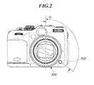
- FIG. 2 is a front view showing a positional relationship between an operation ring and an operation member which are mounted on a camera housing of the electronic still camera shown in FIGS. 1A and 1B .
- FIGS. 3A and 3B are exploded perspective views of a mount base disposed on the camera housing of the electronic still camera shown in FIGS. 1A and 1B , in which FIG. 3A shows an exploded perspective view as viewed from the front, and FIG. 3B shows an exploded perspective view as viewed from the rear.
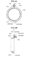
- FIGS. 4A and 4B are views of the mount base shown in FIGS. 3A and 3B , in which FIG. 4A shows a front view, and FIG. 4B shows a side cross-sectional view.
- FIGS. 5A and 5B are exploded perspective views of the operation ring mounted on the camera housing of the electronic still camera shown in FIGS. 1A and 1B , in which FIG. 5A shows an exploded perspective view as viewed from the front, and FIG. 5B shows an exploded perspective view as viewed from the rear.
- FIGS. 6A and 6B are views of the operation ring shown in FIGS. 5A and 5B , in which FIG. 6A shows a rear view, and FIG. 6B shows a side cross-sectional view.
- FIGS. 7A and 7B are views showing a state in which the operation ring shown in FIGS. 5A and 5B has been mounted on the mount base shown in FIGS. 3A and 3B , in which FIG. 7A shows a front view, and FIG. 7B shows a side view.
- FIGS. 8A and 8B are front cross-sectional views of the operation ring shown in FIGS. 5A and 5B and the mount base shown in FIGS. 3A and 3B , in which FIG. 8A shows a state before the operation ring and the mount base are bayonet-coupled, and FIG. 8B shows a state after the operation ring and the mount base have been bayonet-coupled.
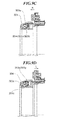
- FIGS. 9A to 9D are side cross-sectional views of the operation ring shown in FIGS. 5A and 5B and the mount base shown in FIGS. 3A and 3B useful in explanation of a bayonet coupling process, in which FIG. 9A shows a state before being bayonet-coupled, FIG. 9B shows a state in the process of being bayonet-coupled, FIG. 9C shows a locked state after being bayonet-coupled, and FIG. 9D shows a state in which the locked state is released after being bayonet-coupled.
- FIG. 10 is a rear enlarged view of a second ring member forming the operation ring shown in FIGS. 5A and 5B .
- FIG. 11 is a side view showing a positional relationship between the second ring member shown in FIG. 10 and photo reflectors for detecting a rotational direction and a rotational amount of the second ring member.
- FIG. 12 is an output timing diagram of the photo reflectors appearing in FIG. 11 .
- FIGS. 13A and 13B are exploded perspective views of a ring adapter bayonet-coupled to the mount base shown in FIGS. 3 and 3B , as viewed from the rear, in which FIG. 13A shows an upper side, and FIG. 13B shows a lower side.
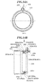
- FIGS. 14A and 14B are views showing a state in which the ring adapter shown in FIGS. 13A and 13B has been mounted on the mount base, in which FIG. 14A shows a font view, and FIG. 14B shows a side cross-sectional view.
- FIG. 15 is a side cross-sectional view showing a state in which a teleconverter has been mounted on the ring adapter shown in FIGS. 13A and 13B .
- FIGS. 16A and 16B are views of a lens adapter which is bayonet-coupled to the mount base shown in FIGS. 3A and 3B , in which FIG. 16A shows a font view, and FIG. 16B shows a rear perspective view.
- FIGS 17A and 17B are views showing a state in which the lens adapter shown in FIGS. 16A and 16B has been mounted on the mount base, in which FIG. 17A shows a front view, and FIG. 17B shows a side cross-sectional view.
- FIGS. 1A and 1B are views of the electronic still camera according to the present embodiment, in which FIG. 1A shows a front perspective view, and FIG. 1B shows a rear perspective view.
- the electronic still camera denoted by reference numeral 101, includes a front cover 201, a lens barrel 102, and a finder 103.
- the front cover 201 is disposed on the front surface of a camera housing which is a main body of the electronic still camera 101, as an exterior of the camera housing.
- the lens barrel 102 constitutes an image pickup optical system of the electronic still camera 101, and an optical system of the finder 103 cooperates with the image pickup optical system of the lens barrel 102 so as to enable a photographer to view an object image through the finder 103.
- the electronic still camera 101 further includes a strobe 104, a power button 105, a release button 106, a zoom lever 107, a mode dial 108, a liquid-crystal display panel 109, and an operation dial 110.
- the strobe 104 irradiates an object with light, and the power button 105 switches on and off of the electronic still camera 101.
- By depressing the release button 106 shooting is performed, and by moving the lens barrel 102 using the zoom lever 107, it is possible to adjust an angle of a photographic image. It is possible to change a shooting mode and the like by operating the mode dial 108, and photographic images and various kinds of information, such as shooting conditions, are displayed on the liquid-crystal display panel 109.
- the operation dial 110 is rotatable clockwise and counterclockwise, and a push operation is possible at the four points of the left, right, top, and bottom, and at the one point of the center.
- the electronic still camera 101 further includes an operation ring 300, and an operation member 202 for locking and unlocking bayonet coupling between the operation ring 300 and the camera housing.
- a first ring member 302 (not shown in FIGS. 1A and 1B ; see FIGS. 5A and 5B ) forming the operation ring 300, and a mount base 203 (see FIG. 3 ) mounted on the camera housing are bayonet-coupled.
- the operation ring 300 is basically formed by an operation ring member 301, the first ring member 302, and a second ring member 305 (see FIGS. 5A and 5B ), and the operation ring member 301 and the second ring member 305 hold the first ring member 302 in a sandwiching manner.
- a photographer can change shooting conditions by rotationally operating the operation ring member 301 in a state in which the operation ring 300 is mounted on the camera housing.
- the operation ring member 301, the first ring member 302, and the second ring member 305 correspond to a rotational operation member, a first member, and a second member, respectively, in the claims appended hereto.
- the lens barrel 102 is extended to the wide position.
- the mode dial 108 the mode of the camera 101 is adjusted e.g. to Tv: shutter speed priority AE mode. It is assumed here that a value of the shutter speed is set to 1/60.
- the shutter speed is set to a value adjacent to the currently set value, e.g. 1/50.
- the shutter speed is set to the other adjacent value, e.g. 1/80.
- the set value is thus changed according to an amount of rotation of the operation ring member 301, and for example, when the operation ring member 301 is rotated clockwise by an amount corresponding to three clicks, the shutter speed is sequentially shifted from 1/60 to 1/50, from 1/50 to 1/40, and from 1/40 to 1/30, whereby it is set to 1/30.
- the set value can be confirmed on a through-the-lens image used in shooting and a display on the liquid-crystal display panel 109.
- a clicking mechanism provided for the operation ring 300, and a mechanism for detecting a rotational direction and a rotational amount of the operation ring member 301 will be described hereinafter.
- Parameters which can be set by the operation of the operation ring member 301 include a shutter speed, an ISO speed, an exposure value, an aperture value, a white balance, a zoom position of the lens barrel 102, and an in-focus position in a manual focus mode, any of which can be selected as desired.
- a shutter speed an ISO speed
- an exposure value an aperture value
- a white balance a zoom position of the lens barrel 102
- an in-focus position in a manual focus mode any of which can be selected as desired.
- the shooting mode when the shooting mode is set to a manual mode, it is possible to change the shutter speed by operating the operation ring member 301, and change the aperture value by operating the operation dial 110. Further, in a reproduction mode for reproducing a photographic image, it is also possible to forward an image or zoom in or out the image by operating the operation ring member 301.
- FIG. 2 is a front view showing a positional relationship between the operation ring 300 and the operation member 202 which are mounted on the camera housing.
- the operation member 202 is provided to the lower right of the operation ring 300, as viewed from the front side of the electronic still camera 101, in the drawings referred to in the following description, the operation member 202 and the operation ring member 301 are shown in a state rotated in a direction of an arrow G, as appropriate. That is, the operation member 202 is illustrated at a vertically upper portion of drawings, as appropriate.
- the mount base 203 is a member which is disposed on the camera housing and to which the first ring member 302 constituting the operation ring 300 is bayonet-coupled.
- FIGS. 3A and 3B are exploded perspective views of the mount base 203, in which FIG. 3A shows the exploded perspective view as viewed from the front, and FIG. 3B shows the exploded perspective view as viewed from the rear.
- FIGS. 4A and 4B are views of the mount base 203, in which FIG. 4A shows a front view, and FIG. 4B shows a side cross-sectional view (taken as indicated by arrows A-A in FIG. 4A ).
- the mount base 203 is formed with three female pawl grooves 203a and three open grooves 203k for being bayonet-coupled to (the first ring member 302 of) the operation ring 300.
- the mount base 203 is disposed such that the three female pawl grooves 203a and the three open grooves 203k are located around the lens barrel 102. Therefore, the three female pawl grooves 203a and the three open grooves 203k function as a first bayonet coupling section for mounting an accessory around the lens barrel.
- a boss 202a formed on the operation member 202 is slidably fitted in a hole 203b formed in the mount base 203.
- a boss 202b formed on the operation member 202 is slidably fitted and locked in a hole 203d formed in the mount base 203. Further, pawl portions 202c formed on the operation member 202 are inserted through holes 203c formed in the mount base 203, respectively, and by using a latch mechanism, such as a snap-fit structure, for these components, the operation member 202 is held by the mount base 203.
- a lock member 204 is slidably fitted and locked in an opening 203j formed in the mount base 203, and can advance and retract in an optical axis direction.
- a boss 203e formed on the mount base 203 is slidably fitted in a hole 204a formed in the lock member 204.
- Bosses 203f formed on the mount base 203 are fitted in holes 206a formed in a holder member 206, respectively.
- a hole 203g formed in the mount base 203 and a hole 206b formed in the holder member 206 are fixed e.g. by fixing means, such as a screw, not shown.
- the boss 203e of the mount base 203 has a lock spring 205 provided thereon between the lock member 204 and the holder member 206, for urging the lock member 204 in a direction of an arrow B (see FIG. 4B ).
- the lock member 204 includes an engaging end face 204c for being engaged with the first ring member 302 constituting the operation member 300. Details of the function of the lock member 204 will be described when describing a method of mounting and dismounting the operation ring 300 on and from the mount base 203.
- a detection unit 10 for detecting a rotational direction and a rotational amount of the operation ring member 301 includes photo reflectors 208a and 208b (first and second photo reflectors) mounted on a flexible printed circuit board 207 e.g. by means of soldering.
- the photo reflectors 208a and 208b are exposed to the front side of the mount base 203 through holes 203h formed in the mount base 203.
- Bosses 203i formed on the mount base 203 are fitted in holes 207c formed in the flexible printed circuit board 207, respectively, and the flexible printed circuit board 207 is fixed to the mount base 203 by adhesive means, such as a double-sided tape.
- adhesive means such as a double-sided tape.
- contact portions of the flexible printed circuit board 207 are connected to a main substrate on which a semiconductor device and the like are mounted for image processing and system processing of the electronic still camera 101, via connectors, for electrical conduction.
- FIGS. 5A and 5B are exploded perspective views of the operation ring 300, in which FIG. 5A shows an exploded perspective view as viewed from the front, and FIG. 5B shows an exploded perspective view as viewed from the rear.
- FIGS. 6A and 6B are views of the operation ring 300, in which FIG. 6A shows a rear view, and FIG. 6B shows a side cross-sectional view (taken as indicated by arrows C-C in FIG. 6A ).
- the operation ring 300 comprises the operation ring member 301 which can be manually operated by a photographer, the first ring member 302 which is bayonet-coupled to the mount base 203, and the second ring member 305 which rotates in unison with the operation ring member 301.
- the first ring member 302 includes male pawl portions 302a formed thereon at three locations for being bayonet-coupled to the mount base 203.
- the male pawl portions 302a function as a second bayonet coupling section which can be coupled and decoupled to and from the first bayonet coupling section.
- a restriction unit 20 which restricts the rotation of the operation ring member 301 comprises a rotation locking member 303 and a rotation locking spring 304.
- the rotation locking member 303 is slidably fitted and latched in a recess 302b formed in the first ring member 302.
- the rotation locking spring 304 is disposed between a rib 302h formed on the first ring member 302 and a wall 303c formed on the rotation locking member 303, and urges the rotation locking member 303 in a direction of an arrow D (see FIG. 6B ).
- a rib 302e formed on the first ring member 302 is slidably fitted and latched in a groove 301b formed in the operation ring member 301.
- a clicking unit 30 that provides a click feeling to a photographer when the operation ring member 301 is rotated comprises a clicking spring 307 and a steel ball 306. The clicking spring 307 and the steel ball 306 are disposed in a hole 302d formed in the first ring member 302.
- Three pawl portions 301a formed on the operation ring member 301 and three holes 305a formed in the second ring member 305 are engaged with each other, respectively, whereby the first ring member 302 is retained from coming off in the optical axis direction.
- the operation ring member 301 thus made integral with the second ring member 305 is rotatably held on the first ring member 302.
- the steel ball 306 is disposed in a position where the center thereof is substantially aligned with the center of an opening 305x formed in a surface of the second ring member 305, which is perpendicular to the optical axis direction, such that part of the steel ball 306 sinks in the opening 305x.
- the opening 305x is formed in plurality in the second ring member 305 such that the openings 305x are circumferentially spaced at regular intervals.
- the steel ball 306 is urged toward the second ring member 305 by an urging force of the clicking spring 307.
- a rib 303a formed on the rotation locking member 303 is urged toward the second ring member 305 by an urging force of the rotation locking spring 304, and is fitted and latched in an opening 305y of the second ring member 305 when the operation ring 300 is not mounted on the camera housing. This restricts the operation ring member 301 and the second ring member 305 from rotating with respect to the first ring member 302.
- the opening 305y is formed in plurality in the second ring member 305 at regular circumferentially spaced intervals.
- the openings 305y correspond to first openings
- the openings 305x correspond to second openings.
- Each opening 305x has a smaller width than each opening 305y.
- the engaging end face 204c of the lock member 204 is brought into abutment with a receiving surface 302f formed on the first ring member 302, as described hereinafter.
- a surface of the second ring member 305 in which the openings 305y are formed is opposed to a surface 302g of the first ring member 302 which is irradiated with light beams emitted from the photo reflectors 208a and 208b, as described hereinafter.
- the operation ring member 301 and the second ring member 305 are engaged with each other at three locations at intervals of 120 degrees
- the manner of the engagement is not limited to this.
- the operation ring member 301 may be fixed to the second ring member 305 with screws.
- FIGS. 7A and 7B are views showing a state in which the operation ring 300 has been mounted on the mount base 203, in which FIG. 7A shows a front view, and FIG. 7B shows a side view.
- FIGS. 8A and 8B are front cross-sectional views of the operation ring 300 and the mount base 203, in which FIG. 8A shows a state before the operation ring 300 and the mount base 203 are bayonet-coupled, and FIG. 8B shows a state after the operation ring 300 and the mount base 203 have been bayonet-coupled.
- the photographer or the like first, holds the operation ring member 301, and aligns the three male pawl portions 302a formed on the first ring member 302 to the three opening grooves 203k formed in the mount base 203.
- the photographer or the like next, pushes the operation ring 300 toward the mount base 203 in the optical axis direction (toward the non-object side), and performs a rotational operation for rotating the operation ring member 301 clockwise up to an end stop. This causes the three male pawl portions 302a of the first ring member 302 to be engaged with the three female pawl grooves 203a of the mount base 203, respectively.
- FIGS. 9A to 9D are side cross-sectional views of the operation ring 300 and the mount base 203 useful in explanation of a bayonet coupling process, in which FIG. 9A shows a state before being bayonet-coupled, FIG. 9B shows a state in the process of being bayonet-coupled, FIG. 9C shows a locked state after being bayonet-coupled, and FIG. 9D shows a state in which the locked state is released after being bayonet-coupled.
- the three male pawl portions 302a of the first ring member 302 restricted from rotation and the three opening grooves 203k of the mount base 203 are aligned, and the operation ring 300 is pushed toward the mount base 203 in the optical axis direction (toward the non-object side).
- a receiving surface 204b of the lock member 204 moves in the direction of the arrow J, which eliminates the urging force of the lock spring 205 which urges the boss 202b on the operation member 202, whereby the operation member 202 is set to be free, and is moved by self weight in the direction of the arrow J.
- the operation ring member 301 is rotated clockwise up to an end stop. This causes the three male pawl portions 302a of the first ring member 302 to be engaged with the three female pawl grooves 203a of the mount base 203, respectively.
- the engaging end face 204c of the lock member 204 being pushed by the receiving surface 302f of the first ring member 302 is moved by the urging force of the lock spring 205 in a direction of an arrow K, and is engaged with a groove 302c of the first ring member 302.
- the first ring member 302 is held in a state restricted from rotation with respect to the mount base 203, as shown in FIG. 9C .
- the receiving surface 204b of the lock member 204 moves in the direction of the arrow K
- the operation member 202 also moves in the direction of the arrow K because the receiving surface 204b is in abutment with the boss 202b on the operation member 202.
- the engaging end face 204c of the lock member 204 moves a receiving surface 303b of the rotation locking member 303 against the urging force of the rotation locking spring 304.
- the rotation locking member 303 locks the second ring member 305 such that the operation ring member 301 and the second ring member 305 do not rotate with respect to the first ring member 302 in accordance with an operation of the operation member 202 by the user.
- the operation ring member 301 rotates the operation ring member 301 counterclockwise up to an end stop, the three male pawl portions 302a formed on the first ring member 302 are moved to the three opening grooves 203k formed in the mount base 203. Therefore, by pulling the operation ring member 301 up toward the object side in the optical axis direction, the operation ring 300 is dismounted from the mount base 203.
- FIG. 10 is a rear enlarged view of the second ring member 305.
- the second ring member 305 has a plurality of T-shaped openings (openings 305x and 305y) formed in a surface thereof perpendicular to the optical axis direction at regular circumferentially spaced intervals, and in the present embodiment, a total of 36 openings are formed at intervals of 10 degrees.
- the opening 305x having a narrower width is used for click feeling generation purposes, and the opening 305y having a wider width is used for detection of the rotational direction and the rotational amount of the operation ring member 301.
- the total of 36 T-shaped openings are provided at intervals of 10 degrees, this is not limitative, but the T-shaped openings can be provided in suitable number at suitable intervals according to the sizes of the operation ring member 301 and the second ring member 305 or a desired operation feeling.
- the steel ball 306 is disposed in a position where the center thereof is substantially aligned with the center of an opening 305x formed in the surface of the second ring member 305 perpendicular to the optical axis direction, in a state urged toward the second ring member 305 by the clicking spring 307.
- the operation ring member 301 is rotationally operated, the second ring member 305 is also rotated in unison, and hence a state in which the steel ball 306 is engaged with each opening 305x of the second ring member 305 and a state in which the steel ball 306 is slid on the surface of the second ring member 305 are switched, which generates a click feeling.
- a width Xa of each opening 305x of the second ring member 305 according to a diameter of the steel ball 306, or by adjusting the urging force of the clicking spring 307, it is possible to obtain a desired clicking force (click feeling).
- FIG. 11 is a side view showing a positional relationship between the second ring member 305, and the photo reflectors 208a and 208b
- FIG. 12 is an output timing diagram of the photo reflectors 208a and 208b.
- the photo reflectors 208a and 208b are disposed such that when click feeling generation is stopped, light beam reflection positions therefor each come to a location at 1/4 (1.25 degrees) of the opening width (5 degrees) on a centerline extending across each opening 305y of the second ring member 305(see FIG. 10 ). Timing of a change in an output signal (reflected light detection signal) from one of the photo reflectors 208a and 208b is thus displaced by 1/4 period from that of a change in an output signal from the other, which makes it possible to detect the rotational direction of the operation ring member 301 which rotates in unison with the second ring member 305.
- the light beam reflection positions for the photo reflectors 208a and 208b are, as shown in FIG. 11 , where light beams emitted from the photo reflectors 208a and 208 irradiate the second ring member 305.
- the light beams from both of the photo reflectors 208a and 208b do not impinge on the second ring member 305, but are irradiated to the surface 302g of the first ring member 302 through the openings 305y.
- the surface 302g of the first ring member 302 is formed of a material which is difficult to reflect light (e.g. a black resin). Therefore, the light beams from both of the photo reflectors 208a and 208b are not reflected by the surface 302g, and as a result, the output signals from the photo reflectors 208a and 208b become "low".
- the second ring member 305 When the second ring member 305 (operation ring member 301) is rotated clockwise or counterclockwise, the light beams emitted from the photo reflectors 208a and 208b come to be irradiated to the second ring member 305.
- the second ring member 305 is formed of a material having a high optical reflectivity (e.g. a metal). Therefore, the light beams emitted from the photo reflectors 208a and 208b are largely reflected by the second ring member 305, and returns to light receiving portions of the photo reflectors 208a and 208b, respectively, whereby the output signals from the photo reflectors 208a and 208b become "high".
- the second ring member 305 is rotated counterclockwise as viewed in FIG. 10 , when the output signal from the photo reflector 208b is switched to "high", the output signal from the photo reflector 208a remains “low”. Conversely, when the output signal from the photo reflector 208b is switched to "high” in a state in which the output signal from the photo reflector 208a remains “low”, the counterclockwise rotation of the second ring member 305 is detected. Similarly, when the output signal from the photo reflector 208a is switched to "high” earlier in a state in which the output signal from the photo reflector 208b remains “low”, the clockwise rotation of the second ring member 305 is detected.
- the rotational amount of the second ring member 305 can be detected from the number of occurrences of switching of the output signals from the photo reflectors 208a and 208b from "low” to "high” (the number of occurrences of switching from "low” to “high” is necessarily equal between the photo reflectors 208a and 208b).
- the photo reflectors 208a and 208b are arranged in a manner adjusted to the positions of adjacent openings 305y.
- the timing of switching of "low” and “high” detection timing
- a metal having a high optical reflectivity is used for the second ring member 305
- a resin having a low optical reflectivity e.g. a black resin
- the second ring member 305 may be formed of a resin having a low optical reflectivity
- the first ring member 302 may be formed of a metal having a high optical reflectivity (e.g. die-cast). In this case, "low" and "high” in FIG.
- the different openings are used for the clicking mechanism and the rotation detection mechanism, more specifically, the openings 305x having a narrower width are used for the clicking mechanism, and the openings 305y having a wider width are used for the rotation detection mechanism, this is not limitative.
- the common openings configured to have a small opening width may be used both for the clicking mechanism and for the rotation detection mechanism.
- the photo reflectors 208a and 208b are used for detection of the rotational direction and rotational amount of the operation ring member 301, a photo interrupter can be used in place of these.
- the electronic still camera enables the photographer to set desired shooting conditions by the manual operation of the operation ring 300 removably mounted on the camera housing by bayonet coupling, and then perform shooting.
- a second embodiment of the present invention will be described.
- the ring adapter is bayonet-coupled to the mount base 203, similarly to the first ring member 302 described in the first embodiment.
- the ring adapter has a structure in which the first ring member 302 is provided with an adapter portion (ring adapter member), on which an optical accessory (e.g. a wide converter lens, a teleconverter lens, or a PL filter), described hereinafter, can be mounted.
- an optical accessory e.g. a wide converter lens, a teleconverter lens, or a PL filter
- FIGS. 13A and 13B are exploded perspective views of the ring adapter, as viewed from the rear, in which FIG. 13A shows an upper side, and FIG. 13B shows a lower side.
- the ring adapter denoted by reference numeral 400, basically comprises a ring adapter member 401, an adapter operation ring 402, and the second ring member 305 (which is the same as the second ring member 305 forming the operation ring 300 according to the first embodiment, and hence the same name and reference numeral are used in the second embodiment).
- the same components as those of the operation ring 300 are denoted by the same reference numerals, and description thereof is omitted.
- the ring adapter member 401 includes male pawl portions 401a formed at three locations for being bayonet-coupled to the mount base 203.
- the rotation locking member 303 is slidably fitted and latched in a recess 401b formed in the ring adapter member 401.
- the rotation locking spring 304 is disposed between a rib 401i of the ring adapter member 401 and the wall 303c of the rotation locking member 303 (see FIG. 5A for details).
- a boss 401e formed on the ring adapter member 401 extends up to a groove 402b formed in the adapter operation ring 402 through an opening groove 402c formed in the adapter operation ring 402. Further, a pawl groove 401h formed in the ring adapter member 401 is engaged with a pawl portion 402d formed on the adapter operation ring 402, whereby the adapter operation ring 402 is retained from coming off in the optical axis direction. Further, the boss 401e formed on the ring adapter member 401 is rotatably and slidably fitted in the groove 402b formed in the adapter operation ring 402.
- the clicking spring 307 and the steel ball 306 are disposed in a hole 401d formed in a surface 401g of the ring adapter member 401, and three pawl portions 402a formed on the adapter operation ring 402 are engaged with the three holes 305a formed in the second ring member 305.
- the adapter operation ring 402 thus made integral with the second ring member 305 is rotatably held on the ring adapter member 401.
- the steel ball 306 is disposed in a position where the center thereof is substantially aligned with the center of one of the openings 305x formed in the second ring member 305, and is urged toward the second ring member 305 by the clicking spring 307.
- the rib 303a formed on the rotation locking member 303 is urged toward the second ring member 305 by the rotation locking spring 304, and is slidably fitted in one of the openings 305y formed in the second ring member 305. This restricts the adapter operation ring 402 and the second ring member 305 from rotating with respect to the ring adapter member 401.
- FIGS. 14A and 14B are views showing a state in which the ring adapter 400 has been mounted on the mount base 203 and is in a locked state after being bayonet-coupled, in which FIG. 14A shows a font view, and FIG. 14B shows a side cross-sectional view (taken as indicated by arrows H-H in FIG. 14A ).
- FIG. 14A shows a font view
- FIG. 14B shows a side cross-sectional view (taken as indicated by arrows H-H in FIG. 14A ).
- the description of the same operation as the bayonet coupling between the operation ring 300 and the mount base 203, described in the first embodiment, is omitted, as appropriate.
- the three male pawl portions 401a formed on the ring adapter member 401 are engaged with the three female pawl grooves 203a formed in the mount base 203.
- the engaging end face 204c of the lock member 204 is moved by the urging force of the lock spring 205 in the direction of the arrow K, and is engaged with a groove 401c of the ring adapter member 401, whereby the ring adapter member 401 is held in a state restricted from rotation with respect to the mount base 203.
- the receiving surface 204b of the lock member 204 moves in the direction of the arrow K, and is brought into abutment with the boss 202b of the operation member 202, whereby the operation member 202 is moved in the direction of the arrow K.
- the engaging end face 204c of the lock member 204 moves the receiving surface 303b of the rotation locking member 303 against the urging force of the rotation locking spring 304.
- This causes the rib 303a of the rotation locking member 303 to be removed from one of the openings 305y of the second ring member 305, so that the adapter operation ring 402 and the second ring member 305 are permitted to rotate in unison.
- a clicking force is generated by the clicking spring 307 and the steel ball 306 disposed in the hole 302d formed in the ring adapter member 401.
- FIG. 15 is a side cross-sectional view showing a state in which a teleconverter as one of optical accessories has been mounted on the ring adapter 400.
- the teleconverter denoted by reference numeral 600, is formed by a teleconversion lens section 601 and a conversion lens section 602.
- a male screw portion 601a formed on the teleconversion lens section 601 and a female screw portion 602a formed on the conversion lens section 602 are fixed by screw fastening.
- a male screw portion 602b formed on the conversion lens section 602 and a female screw portion 401j formed on the ring adapter member 401 are fixed by screw fastening.
- a desired optical accessory e.g. a wide conversion lens or a PL filter
- the ring adapter 400 having the operation ring function.
- FIGS. 16A and 16B are views of the lens adapter, in which FIG. 16A shows a font view, and FIG. 16B shows a rear perspective view.
- FIGS 17A and 17B are views showing a state in which the lens adapter has been mounted on the mount base 203, and is in a locked state after being bayonet-coupled, in which FIG. 17A shows a front view, and FIG. 17B shows a side cross-sectional view (taken as indicated by arrows I-I in FIG. 17A ).
- the description of the same operation as the bayonet coupling between the operation ring 300 and the mount base 203, described in the first embodiment is omitted, as appropriate.
- the engaging end face 204c of the lock member 204 is moved by the urging force of the lock spring 205 in the direction of the arrow K, and is engaged with a groove 501b formed in the lens adapter 501.
- the lens adapter 501 is held in a state restricted from rotation respect to the mount base 203.
- the lens adapter 501 is provided with a female screw portion 501c.
- the electronic still camera according to the third embodiment makes it possible to mount a desired optical accessory, such as the teleconversion lens section 601 or the conversion lens section 602, described with reference to FIG. 15 , depending on shooting conditions, and perform shooting.
- a desired optical accessory such as the teleconversion lens section 601 or the conversion lens section 602, described with reference to FIG. 15 , depending on shooting conditions, and perform shooting.
- the present invention it is also possible to use a lens adapter without the conventional operation ring function.
- the present invention can be applied to various kinds of cameras, such as a single-lens reflex camera, a lens shutter camera, a video camera, and a digital camera.
- the present invention can be applied to optical devices other than cameras, and other devices, and further to a device applied to these cameras, optical devices, and other devices, and components constituting these devices.
- An image pickup apparatus which can provide a rotational operation member around a lens barrel formed with a bayonet coupling section without increasing the apparatus size. Three female pawl grooves and three open grooves are formed in a mount base.
- a first ring member is formed with three male pawl portions for being engaged with the female pawl grooves and open grooves.
- An operation ring member is rotationally operated, and a second ring member rotates in unison therewith.
- Photo reflectors detect rotation of the second ring member.
- a restriction unit restricts rotation of the first ring member when the mount base and the operation ring member are bayonet-coupled.
- a rotation locking member restricts rotation of the operation ring member and the second ring member with respect to the first ring member in accordance with an operation for releasing rotation restriction of the first ring member.
Landscapes
- Physics & Mathematics (AREA)
- General Physics & Mathematics (AREA)
- Engineering & Computer Science (AREA)
- General Engineering & Computer Science (AREA)
- Optics & Photonics (AREA)
- Structure And Mechanism Of Cameras (AREA)
- Studio Devices (AREA)
- Accessories Of Cameras (AREA)
- Lens Barrels (AREA)
Abstract

Description
- The present invention relates to an image pickup apparatus, and an accessory which can be mounted on an image pickup apparatus, and more particularly to an image pickup apparatus formed with a first bayonet coupling section for mounting an accessory around a lens barrel.
- An image pickup apparatus is known which has a bayonet coupling section formed around a lens barrel, for mounting an accessory, such as a wide converter lens or a teleconverter lens (see Japanese Patent Laid-Open Publication No.
2004-272003 - Further, an image pickup apparatus is known which has a rotationally operable ring member provided around a lens barrel, and enables the user to change shooting conditions by rotationally operating the ring member before shooting (see Japanese Patent Laid-Open Publication No.
2011-008970 - In a case where a bayonet coupling section for mounting an accessory is formed around a lens barrel, and a rotationally operable ring member is provided around the lens barrel, it is envisaged to provide the ring member outside the bayonet coupling section formed around the lens barrel.
- However, this arrangement causes a problem that the diameter of the ring member becomes large, which hinders downsizing of the image pickup apparatus.
- The present invention provides an image pickup apparatus which makes it possible to form a bayonet coupling section around a lens barrel, for mounting an accessory, and provide a rotational operation member around the lens barrel, without increasing the size of the image pickup apparatus.
- In a first aspect of the present invention, there is provided an image pickup apparatus as specified in
claims 1 to 7. - In a second aspect of the present invention, there is provided an accessory as specified in claims 8 to 12.
- Further features of the present invention will become apparent from the following description of exemplary embodiments with reference to the attached drawings.
-
FIGS. 1A and 1B are views of an electronic still camera according to the present embodiment, in whichFIG. 1A shows a front perspective view, andFIG. 1B shows a rear perspective view. -
FIG. 2 is a front view showing a positional relationship between an operation ring and an operation member which are mounted on a camera housing of the electronic still camera shown inFIGS. 1A and 1B . -
FIGS. 3A and 3B are exploded perspective views of a mount base disposed on the camera housing of the electronic still camera shown inFIGS. 1A and 1B , in whichFIG. 3A shows an exploded perspective view as viewed from the front, andFIG. 3B shows an exploded perspective view as viewed from the rear. -
FIGS. 4A and 4B are views of the mount base shown inFIGS. 3A and 3B , in whichFIG. 4A shows a front view, andFIG. 4B shows a side cross-sectional view. -
FIGS. 5A and 5B are exploded perspective views of the operation ring mounted on the camera housing of the electronic still camera shown inFIGS. 1A and 1B , in whichFIG. 5A shows an exploded perspective view as viewed from the front, andFIG. 5B shows an exploded perspective view as viewed from the rear. -
FIGS. 6A and 6B are views of the operation ring shown inFIGS. 5A and 5B , in whichFIG. 6A shows a rear view, andFIG. 6B shows a side cross-sectional view. -
FIGS. 7A and 7B are views showing a state in which the operation ring shown inFIGS. 5A and 5B has been mounted on the mount base shown inFIGS. 3A and 3B , in whichFIG. 7A shows a front view, andFIG. 7B shows a side view. -
FIGS. 8A and 8B are front cross-sectional views of the operation ring shown inFIGS. 5A and 5B and the mount base shown inFIGS. 3A and 3B , in whichFIG. 8A shows a state before the operation ring and the mount base are bayonet-coupled, andFIG. 8B shows a state after the operation ring and the mount base have been bayonet-coupled. -
FIGS. 9A to 9D are side cross-sectional views of the operation ring shown inFIGS. 5A and 5B and the mount base shown inFIGS. 3A and 3B useful in explanation of a bayonet coupling process, in whichFIG. 9A shows a state before being bayonet-coupled,FIG. 9B shows a state in the process of being bayonet-coupled,FIG. 9C shows a locked state after being bayonet-coupled, andFIG. 9D shows a state in which the locked state is released after being bayonet-coupled. -
FIG. 10 is a rear enlarged view of a second ring member forming the operation ring shown inFIGS. 5A and 5B . -
FIG. 11 is a side view showing a positional relationship between the second ring member shown inFIG. 10 and photo reflectors for detecting a rotational direction and a rotational amount of the second ring member. -
FIG. 12 is an output timing diagram of the photo reflectors appearing inFIG. 11 . -
FIGS. 13A and 13B are exploded perspective views of a ring adapter bayonet-coupled to the mount base shown inFIGS. 3 and 3B , as viewed from the rear, in whichFIG. 13A shows an upper side, andFIG. 13B shows a lower side. -
FIGS. 14A and 14B are views showing a state in which the ring adapter shown inFIGS. 13A and 13B has been mounted on the mount base, in whichFIG. 14A shows a font view, andFIG. 14B shows a side cross-sectional view. -
FIG. 15 is a side cross-sectional view showing a state in which a teleconverter has been mounted on the ring adapter shown inFIGS. 13A and 13B . -
FIGS. 16A and 16B are views of a lens adapter which is bayonet-coupled to the mount base shown inFIGS. 3A and 3B , in whichFIG. 16A shows a font view, andFIG. 16B shows a rear perspective view. -
FIGS 17A and 17B are views showing a state in which the lens adapter shown inFIGS. 16A and 16B has been mounted on the mount base, in whichFIG. 17A shows a front view, andFIG. 17B shows a side cross-sectional view. - The present invention will now be described in detail below with reference to the accompanying drawings showing embodiments thereof. Although in the present embodiment, an electronic still camera will be described as an example of an image pickup apparatus, the present embodiment is not limited to this.
-
FIGS. 1A and 1B are views of the electronic still camera according to the present embodiment, in whichFIG. 1A shows a front perspective view, andFIG. 1B shows a rear perspective view. The electronic still camera, denoted byreference numeral 101, includes afront cover 201, alens barrel 102, and afinder 103. Thefront cover 201 is disposed on the front surface of a camera housing which is a main body of theelectronic still camera 101, as an exterior of the camera housing. Thelens barrel 102 constitutes an image pickup optical system of theelectronic still camera 101, and an optical system of thefinder 103 cooperates with the image pickup optical system of thelens barrel 102 so as to enable a photographer to view an object image through thefinder 103. - The electronic still
camera 101 further includes astrobe 104, apower button 105, arelease button 106, azoom lever 107, amode dial 108, a liquid-crystal display panel 109, and anoperation dial 110. Thestrobe 104 irradiates an object with light, and thepower button 105 switches on and off of theelectronic still camera 101. By depressing therelease button 106, shooting is performed, and by moving thelens barrel 102 using thezoom lever 107, it is possible to adjust an angle of a photographic image. It is possible to change a shooting mode and the like by operating themode dial 108, and photographic images and various kinds of information, such as shooting conditions, are displayed on the liquid-crystal display panel 109. Theoperation dial 110 is rotatable clockwise and counterclockwise, and a push operation is possible at the four points of the left, right, top, and bottom, and at the one point of the center. - The electronic still
camera 101 further includes anoperation ring 300, and anoperation member 202 for locking and unlocking bayonet coupling between theoperation ring 300 and the camera housing. As described hereinafter, a first ring member 302 (not shown inFIGS. 1A and 1B ; seeFIGS. 5A and 5B ) forming theoperation ring 300, and a mount base 203 (seeFIG. 3 ) mounted on the camera housing are bayonet-coupled. - As will be described hereinafter, the
operation ring 300 is basically formed by anoperation ring member 301, thefirst ring member 302, and a second ring member 305 (seeFIGS. 5A and 5B ), and theoperation ring member 301 and thesecond ring member 305 hold thefirst ring member 302 in a sandwiching manner. A photographer can change shooting conditions by rotationally operating theoperation ring member 301 in a state in which theoperation ring 300 is mounted on the camera housing. Theoperation ring member 301, thefirst ring member 302, and thesecond ring member 305 correspond to a rotational operation member, a first member, and a second member, respectively, in the claims appended hereto. - When the
power button 105 is pressed to start theelectronic still camera 101, thelens barrel 102 is extended to the wide position. By operating themode dial 108, the mode of thecamera 101 is adjusted e.g. to Tv: shutter speed priority AE mode. It is assumed here that a value of the shutter speed is set to 1/60. - When the
operation ring 301 is rotated clockwise as viewed from the rear (from a photographer side) by an amount corresponding to one click, the shutter speed is set to a value adjacent to the currently set value, e.g. 1/50. On the other hand, when theoperation ring 301 is rotated counterclockwise by an amount corresponding to one click, the shutter speed is set to the other adjacent value, e.g. 1/80. The set value is thus changed according to an amount of rotation of theoperation ring member 301, and for example, when theoperation ring member 301 is rotated clockwise by an amount corresponding to three clicks, the shutter speed is sequentially shifted from 1/60 to 1/50, from 1/50 to 1/40, and from 1/40 to 1/30, whereby it is set to 1/30. Note that the set value can be confirmed on a through-the-lens image used in shooting and a display on the liquid-crystal display panel 109. A clicking mechanism provided for theoperation ring 300, and a mechanism for detecting a rotational direction and a rotational amount of theoperation ring member 301 will be described hereinafter. - Parameters which can be set by the operation of the
operation ring member 301 include a shutter speed, an ISO speed, an exposure value, an aperture value, a white balance, a zoom position of thelens barrel 102, and an in-focus position in a manual focus mode, any of which can be selected as desired. Although it is described hereinabove that by operating theoperation ring member 301 when in the shutter speed priority AE mode, the shutter speed is changed, when the shooting mode is set to a mode other than the shutter speed priority AE mode, basically, an operation can be performed using theoperation ring member 301 in the same manner except that a parameter which can be set is different. For example, when the shooting mode is set to a manual mode, it is possible to change the shutter speed by operating theoperation ring member 301, and change the aperture value by operating theoperation dial 110. Further, in a reproduction mode for reproducing a photographic image, it is also possible to forward an image or zoom in or out the image by operating theoperation ring member 301. -
FIG. 2 is a front view showing a positional relationship between theoperation ring 300 and theoperation member 202 which are mounted on the camera housing. Although in the present embodiment, theoperation member 202 is provided to the lower right of theoperation ring 300, as viewed from the front side of theelectronic still camera 101, in the drawings referred to in the following description, theoperation member 202 and theoperation ring member 301 are shown in a state rotated in a direction of an arrow G, as appropriate. That is, theoperation member 202 is illustrated at a vertically upper portion of drawings, as appropriate. - The
mount base 203 is a member which is disposed on the camera housing and to which thefirst ring member 302 constituting theoperation ring 300 is bayonet-coupled.FIGS. 3A and 3B are exploded perspective views of themount base 203, in whichFIG. 3A shows the exploded perspective view as viewed from the front, andFIG. 3B shows the exploded perspective view as viewed from the rear.FIGS. 4A and 4B are views of themount base 203, in whichFIG. 4A shows a front view, andFIG. 4B shows a side cross-sectional view (taken as indicated by arrows A-A inFIG. 4A ). - The
mount base 203 is formed with threefemale pawl grooves 203a and threeopen grooves 203k for being bayonet-coupled to (thefirst ring member 302 of) theoperation ring 300. Themount base 203 is disposed such that the threefemale pawl grooves 203a and the threeopen grooves 203k are located around thelens barrel 102. Therefore, the threefemale pawl grooves 203a and the threeopen grooves 203k function as a first bayonet coupling section for mounting an accessory around the lens barrel. Aboss 202a formed on theoperation member 202 is slidably fitted in ahole 203b formed in themount base 203. Further, aboss 202b formed on theoperation member 202 is slidably fitted and locked in ahole 203d formed in themount base 203. Further,pawl portions 202c formed on theoperation member 202 are inserted throughholes 203c formed in themount base 203, respectively, and by using a latch mechanism, such as a snap-fit structure, for these components, theoperation member 202 is held by themount base 203. - A
lock member 204 is slidably fitted and locked in anopening 203j formed in themount base 203, and can advance and retract in an optical axis direction. Aboss 203e formed on themount base 203 is slidably fitted in ahole 204a formed in thelock member 204.Bosses 203f formed on themount base 203 are fitted inholes 206a formed in aholder member 206, respectively. Ahole 203g formed in themount base 203 and ahole 206b formed in theholder member 206 are fixed e.g. by fixing means, such as a screw, not shown. Theboss 203e of themount base 203 has alock spring 205 provided thereon between thelock member 204 and theholder member 206, for urging thelock member 204 in a direction of an arrow B (seeFIG. 4B ). - The
lock member 204 includes anengaging end face 204c for being engaged with thefirst ring member 302 constituting theoperation member 300. Details of the function of thelock member 204 will be described when describing a method of mounting and dismounting theoperation ring 300 on and from themount base 203. - A
detection unit 10 for detecting a rotational direction and a rotational amount of theoperation ring member 301 includesphoto reflectors circuit board 207 e.g. by means of soldering. Thephoto reflectors mount base 203 throughholes 203h formed in themount base 203. -
Bosses 203i formed on themount base 203 are fitted inholes 207c formed in the flexible printedcircuit board 207, respectively, and the flexible printedcircuit board 207 is fixed to themount base 203 by adhesive means, such as a double-sided tape. Although not shown, contact portions of the flexible printedcircuit board 207 are connected to a main substrate on which a semiconductor device and the like are mounted for image processing and system processing of theelectronic still camera 101, via connectors, for electrical conduction. -
FIGS. 5A and 5B are exploded perspective views of theoperation ring 300, in whichFIG. 5A shows an exploded perspective view as viewed from the front, andFIG. 5B shows an exploded perspective view as viewed from the rear.FIGS. 6A and 6B are views of theoperation ring 300, in whichFIG. 6A shows a rear view, andFIG. 6B shows a side cross-sectional view (taken as indicated by arrows C-C inFIG. 6A ). Theoperation ring 300 comprises theoperation ring member 301 which can be manually operated by a photographer, thefirst ring member 302 which is bayonet-coupled to themount base 203, and thesecond ring member 305 which rotates in unison with theoperation ring member 301. - The
first ring member 302 includesmale pawl portions 302a formed thereon at three locations for being bayonet-coupled to themount base 203. Themale pawl portions 302a function as a second bayonet coupling section which can be coupled and decoupled to and from the first bayonet coupling section. Arestriction unit 20 which restricts the rotation of theoperation ring member 301 comprises arotation locking member 303 and arotation locking spring 304. Therotation locking member 303 is slidably fitted and latched in arecess 302b formed in thefirst ring member 302. Further, therotation locking spring 304 is disposed between arib 302h formed on thefirst ring member 302 and awall 303c formed on therotation locking member 303, and urges therotation locking member 303 in a direction of an arrow D (seeFIG. 6B ). - A
rib 302e formed on thefirst ring member 302 is slidably fitted and latched in agroove 301b formed in theoperation ring member 301. A clickingunit 30 that provides a click feeling to a photographer when theoperation ring member 301 is rotated comprises a clickingspring 307 and asteel ball 306. The clickingspring 307 and thesteel ball 306 are disposed in ahole 302d formed in thefirst ring member 302. - Three
pawl portions 301a formed on theoperation ring member 301 and threeholes 305a formed in thesecond ring member 305 are engaged with each other, respectively, whereby thefirst ring member 302 is retained from coming off in the optical axis direction. Theoperation ring member 301 thus made integral with thesecond ring member 305 is rotatably held on thefirst ring member 302. - The
steel ball 306 is disposed in a position where the center thereof is substantially aligned with the center of anopening 305x formed in a surface of thesecond ring member 305, which is perpendicular to the optical axis direction, such that part of thesteel ball 306 sinks in theopening 305x. Theopening 305x is formed in plurality in thesecond ring member 305 such that theopenings 305x are circumferentially spaced at regular intervals. Thesteel ball 306 is urged toward thesecond ring member 305 by an urging force of the clickingspring 307. Arib 303a formed on therotation locking member 303 is urged toward thesecond ring member 305 by an urging force of therotation locking spring 304, and is fitted and latched in anopening 305y of thesecond ring member 305 when theoperation ring 300 is not mounted on the camera housing. This restricts theoperation ring member 301 and thesecond ring member 305 from rotating with respect to thefirst ring member 302. Theopening 305y is formed in plurality in thesecond ring member 305 at regular circumferentially spaced intervals. In the claims appended hereto, theopenings 305y correspond to first openings, and theopenings 305x correspond to second openings. Eachopening 305x has a smaller width than eachopening 305y. - The
engaging end face 204c of thelock member 204 is brought into abutment with a receivingsurface 302f formed on thefirst ring member 302, as described hereinafter. A surface of thesecond ring member 305 in which theopenings 305y are formed is opposed to asurface 302g of thefirst ring member 302 which is irradiated with light beams emitted from thephoto reflectors - Although in the present embodiment, the
operation ring member 301 and thesecond ring member 305 are engaged with each other at three locations at intervals of 120 degrees, the manner of the engagement is not limited to this. For example, if the size of the camera housing allows, theoperation ring member 301 may be fixed to thesecond ring member 305 with screws. -
FIGS. 7A and 7B are views showing a state in which theoperation ring 300 has been mounted on themount base 203, in whichFIG. 7A shows a front view, andFIG. 7B shows a side view.FIGS. 8A and 8B are front cross-sectional views of theoperation ring 300 and themount base 203, in whichFIG. 8A shows a state before theoperation ring 300 and themount base 203 are bayonet-coupled, andFIG. 8B shows a state after theoperation ring 300 and themount base 203 have been bayonet-coupled. - In a state in which the
operation ring 300 is not mounted on themount base 203, theoperation ring member 301 and thesecond ring member 305 are restricted from rotation with respect to thefirst ring member 302. Therefore, the photographer or the like, first, holds theoperation ring member 301, and aligns the threemale pawl portions 302a formed on thefirst ring member 302 to the three openinggrooves 203k formed in themount base 203. The photographer or the like, next, pushes theoperation ring 300 toward themount base 203 in the optical axis direction (toward the non-object side), and performs a rotational operation for rotating theoperation ring member 301 clockwise up to an end stop. This causes the threemale pawl portions 302a of thefirst ring member 302 to be engaged with the threefemale pawl grooves 203a of themount base 203, respectively. -
FIGS. 9A to 9D are side cross-sectional views of theoperation ring 300 and themount base 203 useful in explanation of a bayonet coupling process, in whichFIG. 9A shows a state before being bayonet-coupled,FIG. 9B shows a state in the process of being bayonet-coupled,FIG. 9C shows a locked state after being bayonet-coupled, andFIG. 9D shows a state in which the locked state is released after being bayonet-coupled. - As shown in
FIG. 9A , the threemale pawl portions 302a of thefirst ring member 302 restricted from rotation and the three openinggrooves 203k of themount base 203 are aligned, and theoperation ring 300 is pushed toward themount base 203 in the optical axis direction (toward the non-object side). This causes theengaging end face 204c of thelock member 204 to be pushed by the receivingsurface 302f of thefirst ring member 302 in a direction of an arrow J against the urging force of thelock spring 205. At the same time, a receivingsurface 204b of thelock member 204 moves in the direction of the arrow J, which eliminates the urging force of thelock spring 205 which urges theboss 202b on theoperation member 202, whereby theoperation member 202 is set to be free, and is moved by self weight in the direction of the arrow J. - As shown in
FIG. 9B , while holding theengaging end face 204c of thelock member 204 in a state pushed by the receivingsurface 302f of thefirst ring member 302 in the direction of the arrow J, theoperation ring member 301 is rotated clockwise up to an end stop. This causes the threemale pawl portions 302a of thefirst ring member 302 to be engaged with the threefemale pawl grooves 203a of themount base 203, respectively. Simultaneously with the timing of this engagement, theengaging end face 204c of thelock member 204 being pushed by the receivingsurface 302f of thefirst ring member 302 is moved by the urging force of thelock spring 205 in a direction of an arrow K, and is engaged with agroove 302c of thefirst ring member 302. - As a consequence, the
first ring member 302 is held in a state restricted from rotation with respect to themount base 203, as shown inFIG. 9C . At the same time, the receivingsurface 204b of thelock member 204 moves in the direction of the arrow K, and theoperation member 202 also moves in the direction of the arrow K because the receivingsurface 204b is in abutment with theboss 202b on theoperation member 202. At this time, theengaging end face 204c of thelock member 204 moves a receivingsurface 303b of therotation locking member 303 against the urging force of therotation locking spring 304. This causes therib 303a of therotation locking member 303 to be removed from one of theopenings 305y of thesecond ring member 305, so that theoperation ring member 301 and thesecond ring member 305 are permitted to rotate in unison. Further, the clickingspring 307 and thesteel ball 306 disposed in thehole 302d of thefirst ring member 302 makes it possible for the user to feel a click when theoperation ring member 301 is rotated. - As shown in
FIG. 9D , when theoperation ring 300 is dismounted from themount base 203, the photographer or the like pushes theoperation member 202 in a direction of an arrow L against the urging force of thelock spring 205. This causes theboss 202b of theoperation member 202 to move the receivingsurface 204b of thelock member 204 in the direction of the arrow L, whereby theengaging end face 204c of thelock member 204 is removed from thegroove 302c of thefirst ring member 302. At this time, therib 303a of therotation locking member 303 is engaged with one of theopenings 305y of thesecond ring member 305 by the urging force of therotation locking spring 304, which restricts the rotation of theoperation ring member 301 and thesecond ring member 305. More specifically, therotation locking member 303 locks thesecond ring member 305 such that theoperation ring member 301 and thesecond ring member 305 do not rotate with respect to thefirst ring member 302 in accordance with an operation of theoperation member 202 by the user. - Then, when the photographer or the like rotates the
operation ring member 301 counterclockwise up to an end stop, the threemale pawl portions 302a formed on thefirst ring member 302 are moved to the three openinggrooves 203k formed in themount base 203. Therefore, by pulling theoperation ring member 301 up toward the object side in the optical axis direction, theoperation ring 300 is dismounted from themount base 203. - A description will be given of the clicking mechanism used when the
operation ring member 301 is rotationally operated with reference toFIG. 10. FIG. 10 is a rear enlarged view of thesecond ring member 305. Thesecond ring member 305 has a plurality of T-shaped openings (openings opening 305x having a narrower width is used for click feeling generation purposes, and theopening 305y having a wider width is used for detection of the rotational direction and the rotational amount of theoperation ring member 301. By forming openings for click feeling generation and detection of rotation in the surface perpendicular to the optical axis direction, it is possible to reduce the thickness of theoperation ring 300, and prevent theelectronic still camera 101 from becoming large in size even when the operation ring function is added. - Although in the present embodiment, the total of 36 T-shaped openings are provided at intervals of 10 degrees, this is not limitative, but the T-shaped openings can be provided in suitable number at suitable intervals according to the sizes of the
operation ring member 301 and thesecond ring member 305 or a desired operation feeling. - The
steel ball 306 is disposed in a position where the center thereof is substantially aligned with the center of anopening 305x formed in the surface of thesecond ring member 305 perpendicular to the optical axis direction, in a state urged toward thesecond ring member 305 by the clickingspring 307. When theoperation ring member 301 is rotationally operated, thesecond ring member 305 is also rotated in unison, and hence a state in which thesteel ball 306 is engaged with eachopening 305x of thesecond ring member 305 and a state in which thesteel ball 306 is slid on the surface of thesecond ring member 305 are switched, which generates a click feeling. By adjusting a width Xa of eachopening 305x of thesecond ring member 305 according to a diameter of thesteel ball 306, or by adjusting the urging force of the clickingspring 307, it is possible to obtain a desired clicking force (click feeling). - Next, a description will be given of the mechanism for detecting a rotational direction and a rotational amount when the
operation ring member 301 is rotationally operated, with reference toFIGS. 10 to 12 .FIG. 11 is a side view showing a positional relationship between thesecond ring member 305, and thephoto reflectors FIG. 12 is an output timing diagram of thephoto reflectors - The
photo reflectors FIG. 10 ). Timing of a change in an output signal (reflected light detection signal) from one of thephoto reflectors operation ring member 301 which rotates in unison with thesecond ring member 305. - More specifically, the light beam reflection positions for the
photo reflectors FIG. 11 , where light beams emitted from thephoto reflectors 208a and 208 irradiate thesecond ring member 305. During stoppage of click feeling generation (stoppage of the second ring member 305), the light beams from both of thephoto reflectors second ring member 305, but are irradiated to thesurface 302g of thefirst ring member 302 through theopenings 305y. Thesurface 302g of thefirst ring member 302 is formed of a material which is difficult to reflect light (e.g. a black resin). Therefore, the light beams from both of thephoto reflectors surface 302g, and as a result, the output signals from thephoto reflectors - When the second ring member 305 (operation ring member 301) is rotated clockwise or counterclockwise, the light beams emitted from the
photo reflectors second ring member 305. Thesecond ring member 305 is formed of a material having a high optical reflectivity (e.g. a metal). Therefore, the light beams emitted from thephoto reflectors second ring member 305, and returns to light receiving portions of thephoto reflectors photo reflectors - "L" and "H" in
FIG. 12 represent that each output signal is "low" and "high", respectively. The output signals from thephoto reflectors tow photo reflectors - If the
second ring member 305 is rotated counterclockwise as viewed inFIG. 10 , when the output signal from thephoto reflector 208b is switched to "high", the output signal from thephoto reflector 208a remains "low". Conversely, when the output signal from thephoto reflector 208b is switched to "high" in a state in which the output signal from thephoto reflector 208a remains "low", the counterclockwise rotation of thesecond ring member 305 is detected. Similarly, when the output signal from thephoto reflector 208a is switched to "high" earlier in a state in which the output signal from thephoto reflector 208b remains "low", the clockwise rotation of thesecond ring member 305 is detected. The rotational amount of thesecond ring member 305 can be detected from the number of occurrences of switching of the output signals from thephoto reflectors photo reflectors - In the present embodiment, from a viewpoint of the size reduction of the flexible printed
circuit board 207, thephoto reflectors adjacent openings 305y. However, it is only necessary that the timing of switching of "low" and "high" (detection timing) is displaced by 1/4 period between the output signals from thephoto reflectors photo reflectors adjacent openings 305y. - Further, although in the present embodiment, a metal having a high optical reflectivity is used for the
second ring member 305, and a resin having a low optical reflectivity (e.g. a black resin) is used for thefirst ring member 302, this may be reversed. More specifically, thesecond ring member 305 may be formed of a resin having a low optical reflectivity, and thefirst ring member 302 may be formed of a metal having a high optical reflectivity (e.g. die-cast). In this case, "low" and "high" inFIG. 12 change places, and hence it is possible to detect the rotational direction of thesecond ring member 305 depending on which of thephoto reflectors second ring member 305 i.e. the operation ring member 301) is stopped. - Further, although in the present embodiment, the different openings are used for the clicking mechanism and the rotation detection mechanism, more specifically, the
openings 305x having a narrower width are used for the clicking mechanism, and theopenings 305y having a wider width are used for the rotation detection mechanism, this is not limitative. For example, to make thesecond ring member 305 smaller in diameter, the common openings configured to have a small opening width may be used both for the clicking mechanism and for the rotation detection mechanism. Further, although thephoto reflectors operation ring member 301, a photo interrupter can be used in place of these. - As described above, the electronic still camera according to the first embodiment enables the photographer to set desired shooting conditions by the manual operation of the
operation ring 300 removably mounted on the camera housing by bayonet coupling, and then perform shooting. - Next, a second embodiment of the present invention will be described. In the second embodiment, a description will be given of a ring adapter as an accessory which can be mounted and dismounted on and from the camera housing, instead of the
operation ring 300. The ring adapter is bayonet-coupled to themount base 203, similarly to thefirst ring member 302 described in the first embodiment. Further, the ring adapter has a structure in which thefirst ring member 302 is provided with an adapter portion (ring adapter member), on which an optical accessory (e.g. a wide converter lens, a teleconverter lens, or a PL filter), described hereinafter, can be mounted. The remaining arrangement of theelectronic still camera 101 is the same as that in the first embodiment, and hence description thereof is omitted. -
FIGS. 13A and 13B are exploded perspective views of the ring adapter, as viewed from the rear, in whichFIG. 13A shows an upper side, andFIG. 13B shows a lower side. The ring adapter, denoted byreference numeral 400, basically comprises aring adapter member 401, anadapter operation ring 402, and the second ring member 305 (which is the same as thesecond ring member 305 forming theoperation ring 300 according to the first embodiment, and hence the same name and reference numeral are used in the second embodiment). Note that in thering adapter 400, the same components as those of theoperation ring 300 are denoted by the same reference numerals, and description thereof is omitted. - The
ring adapter member 401 includesmale pawl portions 401a formed at three locations for being bayonet-coupled to themount base 203. Therotation locking member 303 is slidably fitted and latched in arecess 401b formed in thering adapter member 401. Therotation locking spring 304 is disposed between a rib 401i of thering adapter member 401 and thewall 303c of the rotation locking member 303 (seeFIG. 5A for details). - A
boss 401e formed on thering adapter member 401 extends up to agroove 402b formed in theadapter operation ring 402 through anopening groove 402c formed in theadapter operation ring 402. Further, apawl groove 401h formed in thering adapter member 401 is engaged with apawl portion 402d formed on theadapter operation ring 402, whereby theadapter operation ring 402 is retained from coming off in the optical axis direction. Further, theboss 401e formed on thering adapter member 401 is rotatably and slidably fitted in thegroove 402b formed in theadapter operation ring 402. - The clicking
spring 307 and thesteel ball 306 are disposed in ahole 401d formed in asurface 401g of thering adapter member 401, and threepawl portions 402a formed on theadapter operation ring 402 are engaged with the threeholes 305a formed in thesecond ring member 305. Theadapter operation ring 402 thus made integral with thesecond ring member 305 is rotatably held on thering adapter member 401. - The
steel ball 306 is disposed in a position where the center thereof is substantially aligned with the center of one of theopenings 305x formed in thesecond ring member 305, and is urged toward thesecond ring member 305 by the clickingspring 307. Therib 303a formed on therotation locking member 303 is urged toward thesecond ring member 305 by therotation locking spring 304, and is slidably fitted in one of theopenings 305y formed in thesecond ring member 305. This restricts theadapter operation ring 402 and thesecond ring member 305 from rotating with respect to thering adapter member 401. -
FIGS. 14A and 14B are views showing a state in which thering adapter 400 has been mounted on themount base 203 and is in a locked state after being bayonet-coupled, in whichFIG. 14A shows a font view, andFIG. 14B shows a side cross-sectional view (taken as indicated by arrows H-H inFIG. 14A ). Here, the description of the same operation as the bayonet coupling between theoperation ring 300 and themount base 203, described in the first embodiment, is omitted, as appropriate. - The three
male pawl portions 401a formed on thering adapter member 401 are engaged with the threefemale pawl grooves 203a formed in themount base 203. Theengaging end face 204c of thelock member 204 is moved by the urging force of thelock spring 205 in the direction of the arrow K, and is engaged with agroove 401c of thering adapter member 401, whereby thering adapter member 401 is held in a state restricted from rotation with respect to themount base 203. - At the same time, the receiving
surface 204b of thelock member 204 moves in the direction of the arrow K, and is brought into abutment with theboss 202b of theoperation member 202, whereby theoperation member 202 is moved in the direction of the arrow K.
At this time, theengaging end face 204c of thelock member 204 moves the receivingsurface 303b of therotation locking member 303 against the urging force of therotation locking spring 304. This causes therib 303a of therotation locking member 303 to be removed from one of theopenings 305y of thesecond ring member 305, so that theadapter operation ring 402 and thesecond ring member 305 are permitted to rotate in unison. Further, when theadapter operation ring 402 is rotated, a clicking force is generated by the clickingspring 307 and thesteel ball 306 disposed in thehole 302d formed in thering adapter member 401. -
FIG. 15 is a side cross-sectional view showing a state in which a teleconverter as one of optical accessories has been mounted on thering adapter 400. The teleconverter, denoted byreference numeral 600, is formed by ateleconversion lens section 601 and aconversion lens section 602. Amale screw portion 601a formed on theteleconversion lens section 601 and afemale screw portion 602a formed on theconversion lens section 602 are fixed by screw fastening. Further, amale screw portion 602b formed on theconversion lens section 602 and afemale screw portion 401j formed on thering adapter member 401 are fixed by screw fastening. - As described above, in the present embodiment, it is possible to develop a system in which a desired optical accessory (e.g. a wide conversion lens or a PL filter) is mounted according to shooting conditions, using the
ring adapter 400 having the operation ring function. - Next, a third embodiment of the present invention will be described. In the third embodiment, a description will be given of arrangement of an electronic still camera as an image pickup apparatus in which the lens adapter can be mounted and dismounted on and from the camera housing instead of the
operation ring 300.FIGS. 16A and 16B are views of the lens adapter, in whichFIG. 16A shows a font view, andFIG. 16B shows a rear perspective view.FIGS 17A and 17B are views showing a state in which the lens adapter has been mounted on themount base 203, and is in a locked state after being bayonet-coupled, in whichFIG. 17A shows a front view, andFIG. 17B shows a side cross-sectional view (taken as indicated by arrows I-I inFIG. 17A ). Also in the present embodiment, the description of the same operation as the bayonet coupling between theoperation ring 300 and themount base 203, described in the first embodiment, is omitted, as appropriate. - Three
male pawl portions 501a formed on the lens adapter, denoted byreference numeral 501, are engaged with thefemale pawl grooves 203a formed in themount base 203. Theengaging end face 204c of thelock member 204 is moved by the urging force of thelock spring 205 in the direction of the arrow K, and is engaged with agroove 501b formed in thelens adapter 501. As a consequence, thelens adapter 501 is held in a state restricted from rotation respect to themount base 203. Further, thelens adapter 501 is provided with afemale screw portion 501c. - The electronic still camera according to the third embodiment makes it possible to mount a desired optical accessory, such as the
teleconversion lens section 601 or theconversion lens section 602, described with reference toFIG. 15 , depending on shooting conditions, and perform shooting. - While the present invention has been described with reference to exemplary embodiments, it is to be understood that the invention is not limited to the disclosed exemplary embodiments. The scope of the following claims is to be accorded the broadest interpretation so as to encompass all such modifications and equivalent structures and functions.
- For example, in the present invention, it is also possible to use a lens adapter without the conventional operation ring function. Further, the present invention can be applied to various kinds of cameras, such as a single-lens reflex camera, a lens shutter camera, a video camera, and a digital camera. Further, the present invention can be applied to optical devices other than cameras, and other devices, and further to a device applied to these cameras, optical devices, and other devices, and components constituting these devices.
An image pickup apparatus which can provide a rotational operation member around a lens barrel formed with a bayonet coupling section without increasing the apparatus size. Three female pawl grooves and three open grooves are formed in a mount base. A first ring member is formed with three male pawl portions for being engaged with the female pawl grooves and open grooves. An operation ring member is rotationally operated, and a second ring member rotates in unison therewith. Photo reflectors detect rotation of the second ring member. A restriction unit restricts rotation of the first ring member when the mount base and the operation ring member are bayonet-coupled. A rotation locking member restricts rotation of the operation ring member and the second ring member with respect to the first ring member in accordance with an operation for releasing rotation restriction of the first ring member.
Claims (12)
- An image pickup apparatus (101) comprising:a first bayonet coupling section (203a, 203k) which is formed around a lens barrel;a first member (302) configured to have a second bayonet coupling section (302a) formed thereon, said second bayonet coupling section (302a) being capable of being engaged with said first bayonet coupling section (203a, 203k);a rotational operation member (301) configured to rotate with respect to said first member (302), by being rotationally operated by a user;a second member (305) configured to rotate in unison with said rotational operation member (301) when said rotational operation member is rotationally operated by the user;a detection unit (10) configured to detect rotation of said second member (305);a first lock member (204) configured to restrict rotation of said first member (302) with respect to said first bayonet coupling section (203a, 203k) when said first bayonet coupling section (203a, 203k) and said second bayonet coupling section (302a) are engaged with each other; anda second lock member (303) configured to restrict rotation of said rotational operation member (301) and said second member (305) with respect to said first member (302) in accordance with an operation for releasing rotation restriction of said first member.
- The image pickup apparatus according to claim 1, wherein a plurality of first openings (305y) are formed in said second member (305) at regular circumferentially spaced intervals; and
wherein said second lock member (303, 303a) is fitted in one of said first openings (305y) in accordance with an operation of said rotational operation member by the user. - The image pickup apparatus according to claim 2, wherein said detection unit (10) includes a first photo reflector and a second photo reflector (208a, 208b) configured to emit respective light beams to said second member, and detect reflective lights which are reflected by said second member (305), and reflective lights which pass through said first openings (305y) and are thereby reflected by said first member (302),
wherein respective surfaces of said first member and said second member that are to be irradiated with the respective light beams emitted from said first photo reflector and said second photo reflector are different in reflectivity to the light beams,
wherein when said rotational operation member (301) is rotated, a period at which a reflective light from said second member (305) and a reflective light from said first member (302) are alternately detected is displaced by 1/4 period between said first photo reflector and said second photo reflector (208a, 208b), and
wherein a rotational direction of said rotational operation member (301) is detected based on displacement of timing of switching between detection of the reflective light from said second member (305) and detection of the reflective light from said first member (302), between said first photo reflector and said second photo reflector (208a, 208b). - The image pickup apparatus according to claim 4, wherein a rotational amount of said rotational operation member (301) is detected based on the number of times of switching between detection of the reflective light from said second member (305) and detection of the reflective light from said first member (302) by each of said first photo reflector and said second photo reflector (208a, 208b).
- The image pickup apparatus according to claim 2, wherein a plurality of second openings (305x) each having a smaller width than said first openings (305y) are formed in said second member (305) at regular circumferentially spaced intervals,
the image pickup apparatus further comprising:a steel ball (306) which is disposed such that part thereof sinks in one of the second openings formed (305x) in said second member, anda clicking spring (307) configured to urge said steel ball (306) toward said second member, andwherein when said second member (305) rotates with respect to said first member (302), a click feeling is provided to the user by switching of a state in which said steel ball (306) is engaged with one of the second openings (305x) of said second member and a state in which said steel ball (306) is slid on a surface of said second member (305). - The image pickup apparatus according to claim 1, wherein said first member (302, 401, 501) includes an adapter portion (401) on which an optical accessory can be mounted.
- The image pickup apparatus according to claim 6, wherein the optical accessory is one of a wide converter lens, a teleconverter lens (601), and a filter.
- An accessory (400) that can be mounted on an image pickup apparatus (101) having a first bayonet coupling section (203a) formed around a lens barrel (102, 203), comprising:a first member (302, 401, 501) configured to have a second bayonet coupling section (401a, 501a) formed thereon, said second bayonet coupling section (401a, 501a) being capable of being engaged with said first bayonet coupling section (203a);a rotational operation member (402) configured to rotate with respect to said first member (401), by being rotationally operated by a user;a second member (305) configured to rotate in unison with said rotational operation member (402) when said rotational operation member is rotationally operated by the user; anda lock member (303) configured to restrict rotation of said rotational operation member (402) and said second member(305) with respect to said first member (302, 401) in accordance with an operation for dismounting the accessory (400) from the image pickup apparatus (101).
- The accessory according to claim 8, wherein a plurality of first openings (305y) are formed in said second member (305) at regular circumferentially spaced intervals, and
wherein said lock member (303, 303a) is fitted in one of said first openings (305y) in accordance with an operation of said rotational operation member by the user. - The accessory according to claim 9, wherein a plurality of second openings (305x) each having a smaller width than said first openings (305y) are formed in said second member (305) at regular circumferentially spaced intervals,
the image pickup apparatus further comprising:a steel ball (306) which is disposed such that part thereof sinks in one of the second openings (305x) formed in said second member, anda clicking spring (307) configured to urge said steel ball (306) toward said second member (305), andwherein when said second member (305) rotates with respect to said first member (302, 401, 501), a click feeling is provided to the user by switching of a state in which said steel ball (306) is engaged with one of the second openings (305x) of said second ring member and a state in which said steel ball (306) is slid on a surface of said second ring member. - The accessory according to claim 8, wherein said first member (302, 401, 501) includes an adapter portion (401) on which an optical accessory can be mounted.
- The accessory according to claim 11, wherein the optical accessory is one of a wide converter lens, a teleconverter lens (601), and a filter.
Applications Claiming Priority (1)
| Application Number | Priority Date | Filing Date | Title |
|---|---|---|---|
| JP2011201673A JP5896662B2 (en) | 2011-09-15 | 2011-09-15 | Imaging apparatus and accessories |
Publications (2)
| Publication Number | Publication Date |
|---|---|
| EP2570849A1 true EP2570849A1 (en) | 2013-03-20 |
| EP2570849B1 EP2570849B1 (en) | 2015-03-25 |
Family
ID=47257370
Family Applications (1)
| Application Number | Title | Priority Date | Filing Date |
|---|---|---|---|
| EP12184199.3A Not-in-force EP2570849B1 (en) | 2011-09-15 | 2012-09-13 | Image pickup apparatus including bayonet coupling section in lens barrel, and accessory |
Country Status (5)
| Country | Link |
|---|---|
| US (1) | US8858101B2 (en) |
| EP (1) | EP2570849B1 (en) |
| JP (1) | JP5896662B2 (en) |
| CN (1) | CN102998879B (en) |
| RU (1) | RU2524750C2 (en) |
Cited By (1)
| Publication number | Priority date | Publication date | Assignee | Title |
|---|---|---|---|---|
| GB2552179A (en) * | 2016-07-12 | 2018-01-17 | Global Boom International Ltd | A back-locking lens fixing device and a lens adapter employing such |
Families Citing this family (22)
| Publication number | Priority date | Publication date | Assignee | Title |
|---|---|---|---|---|
| WO2014057726A1 (en) * | 2012-10-11 | 2014-04-17 | ソニー株式会社 | Position detection device, lens barrel, and image pickup device |
| JP6081887B2 (en) * | 2013-08-19 | 2017-02-15 | 日本電産コパル株式会社 | Imaging device |
| JP6611529B2 (en) * | 2015-09-11 | 2019-11-27 | キヤノン株式会社 | Electronics |
| US9995990B2 (en) | 2015-12-15 | 2018-06-12 | Gopro, Inc. | Removable camera lens cover |
| WO2017139929A1 (en) * | 2016-02-17 | 2017-08-24 | SZ DJI Technology Co., Ltd. | Mode selection assembly and method for selecting imaging mode |
| CN107404603B (en) * | 2016-05-19 | 2021-05-04 | 环球兴国际有限公司 | Lens adapter and its back-lock lens mount |
| RU2724453C2 (en) | 2017-05-31 | 2020-06-23 | Кэнон Кабусики Кайся | Lens device, an image capturing device on which a lens device can be mounted, and a camera system |
| CN208386721U (en) * | 2017-05-31 | 2019-01-15 | 佳能株式会社 | Accessory, the picture pick-up device and camera system that the accessory can be installed |
| SG10202103518RA (en) | 2017-05-31 | 2021-05-28 | Canon Kk | Adapter device, imaging apparatus, and accessory |
| US11656426B2 (en) * | 2018-07-19 | 2023-05-23 | Canon Kabushiki Kaisha | Lens apparatus and imaging apparatus |
| JP7374628B2 (en) * | 2018-09-21 | 2023-11-07 | キヤノン株式会社 | Imaging equipment, optics, and accessory equipment |
| US11425286B2 (en) | 2020-03-31 | 2022-08-23 | Gopro, Inc. | Housing assembly for image capture devices |
| CN111458959B (en) * | 2020-04-28 | 2025-05-27 | 深圳市锐丽珑精密光学有限公司 | A filter mounting structure |
| US11630376B2 (en) * | 2020-06-18 | 2023-04-18 | Gopro, Inc. | Removable lens accessories for image capture devices |
| USD967890S1 (en) | 2020-08-28 | 2022-10-25 | Gopro, Inc. | Camera lens attachment |
| USD974450S1 (en) | 2020-08-28 | 2023-01-03 | Gopro, Inc. | Camera lens attachment |
| US11600023B2 (en) | 2020-08-31 | 2023-03-07 | Gopro, Inc. | Optical center calibration |
| US11528417B2 (en) | 2020-08-31 | 2022-12-13 | Gopro, Inc. | Calibrating an image capture device with a detachable lens |
| CN112817200A (en) * | 2021-01-28 | 2021-05-18 | 常乐 | Magnetic type multifunctional light reduction mirror |
| CN115022441B (en) * | 2021-03-03 | 2023-08-25 | 荣耀终端有限公司 | Electronic equipment |
| USD1104116S1 (en) | 2024-06-26 | 2025-12-02 | Gopro, Inc. | Camera lens |
| USD1104115S1 (en) | 2024-06-26 | 2025-12-02 | Gopro, Inc. | Camera lens |
Citations (6)
| Publication number | Priority date | Publication date | Assignee | Title |
|---|---|---|---|---|
| JP2004272003A (en) | 2003-03-10 | 2004-09-30 | Canon Inc | Imaging device |
| US20060067679A1 (en) * | 2004-09-27 | 2006-03-30 | Fuji Photo Film Co., Ltd. | Device and camera |
| US20070020987A1 (en) * | 2005-07-25 | 2007-01-25 | Hideo Shirako | Adapter ring for rotation of photographing lens barrel |
| US20090051806A1 (en) * | 2004-02-25 | 2009-02-26 | Arnold & Richter Cine Technik Gmbh & Co.Betriebs Kg | Device for Connecting a Camera Lens to a Movie Camera |
| JP2011008970A (en) | 2009-06-23 | 2011-01-13 | Canon Inc | Electronic device |
| US20110194189A1 (en) * | 2010-02-05 | 2011-08-11 | Canon Kabushiki Kaisha | Image pickup lens, image pickup apparatus, and control method of the image pickup apparatus |
Family Cites Families (5)
| Publication number | Priority date | Publication date | Assignee | Title |
|---|---|---|---|---|
| JPS5922927B2 (en) * | 1977-02-04 | 1984-05-30 | キヤノン株式会社 | Camera accessory mounting device |
| JP3450780B2 (en) * | 2000-02-01 | 2003-09-29 | ペンタックス株式会社 | Bayonet fixing device for annular member and zoom lens barrel |
| JP2003195414A (en) * | 2001-12-25 | 2003-07-09 | Olympus Optical Co Ltd | Lens adapter device |
| JP4321605B2 (en) * | 2007-02-26 | 2009-08-26 | ソニー株式会社 | Lens adapter and imaging device |
| KR101567816B1 (en) * | 2009-07-16 | 2015-11-11 | 삼성전자주식회사 | Lens Adapter |
-
2011
- 2011-09-15 JP JP2011201673A patent/JP5896662B2/en not_active Expired - Fee Related
-
2012
- 2012-09-07 RU RU2012138543/28A patent/RU2524750C2/en not_active IP Right Cessation
- 2012-09-13 EP EP12184199.3A patent/EP2570849B1/en not_active Not-in-force
- 2012-09-14 US US13/616,835 patent/US8858101B2/en not_active Expired - Fee Related
- 2012-09-14 CN CN201210342431.7A patent/CN102998879B/en not_active Expired - Fee Related
Patent Citations (6)
| Publication number | Priority date | Publication date | Assignee | Title |
|---|---|---|---|---|
| JP2004272003A (en) | 2003-03-10 | 2004-09-30 | Canon Inc | Imaging device |
| US20090051806A1 (en) * | 2004-02-25 | 2009-02-26 | Arnold & Richter Cine Technik Gmbh & Co.Betriebs Kg | Device for Connecting a Camera Lens to a Movie Camera |
| US20060067679A1 (en) * | 2004-09-27 | 2006-03-30 | Fuji Photo Film Co., Ltd. | Device and camera |
| US20070020987A1 (en) * | 2005-07-25 | 2007-01-25 | Hideo Shirako | Adapter ring for rotation of photographing lens barrel |
| JP2011008970A (en) | 2009-06-23 | 2011-01-13 | Canon Inc | Electronic device |
| US20110194189A1 (en) * | 2010-02-05 | 2011-08-11 | Canon Kabushiki Kaisha | Image pickup lens, image pickup apparatus, and control method of the image pickup apparatus |
Cited By (1)
| Publication number | Priority date | Publication date | Assignee | Title |
|---|---|---|---|---|
| GB2552179A (en) * | 2016-07-12 | 2018-01-17 | Global Boom International Ltd | A back-locking lens fixing device and a lens adapter employing such |
Also Published As
| Publication number | Publication date |
|---|---|
| RU2524750C2 (en) | 2014-08-10 |
| CN102998879A (en) | 2013-03-27 |
| RU2012138543A (en) | 2014-03-20 |
| US8858101B2 (en) | 2014-10-14 |
| EP2570849B1 (en) | 2015-03-25 |
| CN102998879B (en) | 2015-01-07 |
| JP5896662B2 (en) | 2016-03-30 |
| US20130071101A1 (en) | 2013-03-21 |
| JP2013061602A (en) | 2013-04-04 |
Similar Documents
| Publication | Publication Date | Title |
|---|---|---|
| EP2570849B1 (en) | Image pickup apparatus including bayonet coupling section in lens barrel, and accessory | |
| US5991097A (en) | Lens barrel having a linear guide mechanism | |
| GB2344661A (en) | Lens barrel having a linear guide mechanism | |
| GB2309551A (en) | Lens barrel having a linear guide groove | |
| JP6064513B2 (en) | Lens barrel and imaging device | |
| JP2009192581A (en) | Lens-barrel and imaging apparatus | |
| US6973261B2 (en) | Camera | |
| US10379423B2 (en) | Image-capturing apparatus | |
| JP2004287259A (en) | Camera | |
| JP3778078B2 (en) | camera | |
| JP2004252200A (en) | Lens mirror frame | |
| JP5962432B2 (en) | Lens barrel and imaging device | |
| JP2004287257A (en) | Camera with built-in stroboscope | |
| JP2000155359A (en) | camera | |
| JPH103118A (en) | Camera | |
| JP2004287260A (en) | Camera | |
| JP2005017699A (en) | Camera | |
| JP4514211B2 (en) | Optical equipment | |
| JP3339125B2 (en) | camera | |
| JP3300605B2 (en) | Linear guide mechanism for lens barrel | |
| JPH09281577A (en) | Camera | |
| JP2004117595A (en) | Camera | |
| JP2007094110A (en) | Camera with built-in stroboscope | |
| JP2011141506A (en) | Camera | |
| JPH09211572A (en) | Pop-up type flashing device for camera |
Legal Events
| Date | Code | Title | Description |
|---|---|---|---|
| PUAI | Public reference made under article 153(3) epc to a published international application that has entered the european phase |
Free format text: ORIGINAL CODE: 0009012 |
|
| AK | Designated contracting states |
Kind code of ref document: A1 Designated state(s): AL AT BE BG CH CY CZ DE DK EE ES FI FR GB GR HR HU IE IS IT LI LT LU LV MC MK MT NL NO PL PT RO RS SE SI SK SM TR |
|
| AX | Request for extension of the european patent |
Extension state: BA ME |
|
| RIN1 | Information on inventor provided before grant (corrected) |
Inventor name: IDERA, SHUICHI |
|
| 17P | Request for examination filed |
Effective date: 20130920 |
|
| RBV | Designated contracting states (corrected) |
Designated state(s): AL AT BE BG CH CY CZ DE DK EE ES FI FR GB GR HR HU IE IS IT LI LT LU LV MC MK MT NL NO PL PT RO RS SE SI SK SM TR |
|
| RIC1 | Information provided on ipc code assigned before grant |
Ipc: G02B 7/10 20060101ALI20140828BHEP Ipc: G03B 17/56 20060101ALI20140828BHEP Ipc: G03B 17/14 20060101AFI20140828BHEP |
|
| GRAP | Despatch of communication of intention to grant a patent |
Free format text: ORIGINAL CODE: EPIDOSNIGR1 |
|
| INTG | Intention to grant announced |
Effective date: 20141006 |
|
| RIN1 | Information on inventor provided before grant (corrected) |
Inventor name: IDERA, SHUICHI |
|
| GRAS | Grant fee paid |
Free format text: ORIGINAL CODE: EPIDOSNIGR3 |
|
| GRAA | (expected) grant |
Free format text: ORIGINAL CODE: 0009210 |
|
| AK | Designated contracting states |
Kind code of ref document: B1 Designated state(s): AL AT BE BG CH CY CZ DE DK EE ES FI FR GB GR HR HU IE IS IT LI LT LU LV MC MK MT NL NO PL PT RO RS SE SI SK SM TR |
|
| REG | Reference to a national code |
Ref country code: GB Ref legal event code: FG4D |
|
| REG | Reference to a national code |
Ref country code: CH Ref legal event code: EP |
|
| REG | Reference to a national code |
Ref country code: IE Ref legal event code: FG4D |
|
| REG | Reference to a national code |
Ref country code: DE Ref legal event code: R096 Ref document number: 602012006119 Country of ref document: DE Effective date: 20150507 |
|
| REG | Reference to a national code |
Ref country code: AT Ref legal event code: REF Ref document number: 718207 Country of ref document: AT Kind code of ref document: T Effective date: 20150515 |
|
| PG25 | Lapsed in a contracting state [announced via postgrant information from national office to epo] |
Ref country code: LT Free format text: LAPSE BECAUSE OF FAILURE TO SUBMIT A TRANSLATION OF THE DESCRIPTION OR TO PAY THE FEE WITHIN THE PRESCRIBED TIME-LIMIT Effective date: 20150325 Ref country code: SE Free format text: LAPSE BECAUSE OF FAILURE TO SUBMIT A TRANSLATION OF THE DESCRIPTION OR TO PAY THE FEE WITHIN THE PRESCRIBED TIME-LIMIT Effective date: 20150325 Ref country code: HR Free format text: LAPSE BECAUSE OF FAILURE TO SUBMIT A TRANSLATION OF THE DESCRIPTION OR TO PAY THE FEE WITHIN THE PRESCRIBED TIME-LIMIT Effective date: 20150325 Ref country code: FI Free format text: LAPSE BECAUSE OF FAILURE TO SUBMIT A TRANSLATION OF THE DESCRIPTION OR TO PAY THE FEE WITHIN THE PRESCRIBED TIME-LIMIT Effective date: 20150325 |
|
| REG | Reference to a national code |
Ref country code: AT Ref legal event code: MK05 Ref document number: 718207 Country of ref document: AT Kind code of ref document: T Effective date: 20150325 |
|
| REG | Reference to a national code |
Ref country code: LT Ref legal event code: MG4D |
|
| PG25 | Lapsed in a contracting state [announced via postgrant information from national office to epo] |
Ref country code: RS Free format text: LAPSE BECAUSE OF FAILURE TO SUBMIT A TRANSLATION OF THE DESCRIPTION OR TO PAY THE FEE WITHIN THE PRESCRIBED TIME-LIMIT Effective date: 20150325 Ref country code: GR Free format text: LAPSE BECAUSE OF FAILURE TO SUBMIT A TRANSLATION OF THE DESCRIPTION OR TO PAY THE FEE WITHIN THE PRESCRIBED TIME-LIMIT Effective date: 20150626 Ref country code: LV Free format text: LAPSE BECAUSE OF FAILURE TO SUBMIT A TRANSLATION OF THE DESCRIPTION OR TO PAY THE FEE WITHIN THE PRESCRIBED TIME-LIMIT Effective date: 20150325 |
|
| PG25 | Lapsed in a contracting state [announced via postgrant information from national office to epo] |
Ref country code: NL Free format text: LAPSE BECAUSE OF FAILURE TO SUBMIT A TRANSLATION OF THE DESCRIPTION OR TO PAY THE FEE WITHIN THE PRESCRIBED TIME-LIMIT Effective date: 20150325 |
|
| PG25 | Lapsed in a contracting state [announced via postgrant information from national office to epo] |
Ref country code: SK Free format text: LAPSE BECAUSE OF FAILURE TO SUBMIT A TRANSLATION OF THE DESCRIPTION OR TO PAY THE FEE WITHIN THE PRESCRIBED TIME-LIMIT Effective date: 20150325 Ref country code: PT Free format text: LAPSE BECAUSE OF FAILURE TO SUBMIT A TRANSLATION OF THE DESCRIPTION OR TO PAY THE FEE WITHIN THE PRESCRIBED TIME-LIMIT Effective date: 20150727 Ref country code: ES Free format text: LAPSE BECAUSE OF FAILURE TO SUBMIT A TRANSLATION OF THE DESCRIPTION OR TO PAY THE FEE WITHIN THE PRESCRIBED TIME-LIMIT Effective date: 20150325 Ref country code: EE Free format text: LAPSE BECAUSE OF FAILURE TO SUBMIT A TRANSLATION OF THE DESCRIPTION OR TO PAY THE FEE WITHIN THE PRESCRIBED TIME-LIMIT Effective date: 20150325 Ref country code: CZ Free format text: LAPSE BECAUSE OF FAILURE TO SUBMIT A TRANSLATION OF THE DESCRIPTION OR TO PAY THE FEE WITHIN THE PRESCRIBED TIME-LIMIT Effective date: 20150325 Ref country code: RO Free format text: LAPSE BECAUSE OF FAILURE TO SUBMIT A TRANSLATION OF THE DESCRIPTION OR TO PAY THE FEE WITHIN THE PRESCRIBED TIME-LIMIT Effective date: 20150325 |
|
| PG25 | Lapsed in a contracting state [announced via postgrant information from national office to epo] |
Ref country code: AT Free format text: LAPSE BECAUSE OF FAILURE TO SUBMIT A TRANSLATION OF THE DESCRIPTION OR TO PAY THE FEE WITHIN THE PRESCRIBED TIME-LIMIT Effective date: 20150325 Ref country code: IS Free format text: LAPSE BECAUSE OF FAILURE TO SUBMIT A TRANSLATION OF THE DESCRIPTION OR TO PAY THE FEE WITHIN THE PRESCRIBED TIME-LIMIT Effective date: 20150725 Ref country code: PL Free format text: LAPSE BECAUSE OF FAILURE TO SUBMIT A TRANSLATION OF THE DESCRIPTION OR TO PAY THE FEE WITHIN THE PRESCRIBED TIME-LIMIT Effective date: 20150325 |
|
| REG | Reference to a national code |
Ref country code: DE Ref legal event code: R097 Ref document number: 602012006119 Country of ref document: DE |
|
| PG25 | Lapsed in a contracting state [announced via postgrant information from national office to epo] |
Ref country code: DK Free format text: LAPSE BECAUSE OF FAILURE TO SUBMIT A TRANSLATION OF THE DESCRIPTION OR TO PAY THE FEE WITHIN THE PRESCRIBED TIME-LIMIT Effective date: 20150325 |
|
| PLBE | No opposition filed within time limit |
Free format text: ORIGINAL CODE: 0009261 |
|
| STAA | Information on the status of an ep patent application or granted ep patent |
Free format text: STATUS: NO OPPOSITION FILED WITHIN TIME LIMIT |
|
| 26N | No opposition filed |
Effective date: 20160105 |
|
| PG25 | Lapsed in a contracting state [announced via postgrant information from national office to epo] |
Ref country code: IT Free format text: LAPSE BECAUSE OF FAILURE TO SUBMIT A TRANSLATION OF THE DESCRIPTION OR TO PAY THE FEE WITHIN THE PRESCRIBED TIME-LIMIT Effective date: 20150325 Ref country code: MC Free format text: LAPSE BECAUSE OF FAILURE TO SUBMIT A TRANSLATION OF THE DESCRIPTION OR TO PAY THE FEE WITHIN THE PRESCRIBED TIME-LIMIT Effective date: 20150325 Ref country code: LU Free format text: LAPSE BECAUSE OF FAILURE TO SUBMIT A TRANSLATION OF THE DESCRIPTION OR TO PAY THE FEE WITHIN THE PRESCRIBED TIME-LIMIT Effective date: 20150913 |
|
| REG | Reference to a national code |
Ref country code: CH Ref legal event code: PL |
|
| PG25 | Lapsed in a contracting state [announced via postgrant information from national office to epo] |
Ref country code: SI Free format text: LAPSE BECAUSE OF FAILURE TO SUBMIT A TRANSLATION OF THE DESCRIPTION OR TO PAY THE FEE WITHIN THE PRESCRIBED TIME-LIMIT Effective date: 20150325 |
|
| REG | Reference to a national code |
Ref country code: IE Ref legal event code: MM4A |
|
| REG | Reference to a national code |
Ref country code: FR Ref legal event code: ST Effective date: 20160531 |
|
| PG25 | Lapsed in a contracting state [announced via postgrant information from national office to epo] |
Ref country code: IE Free format text: LAPSE BECAUSE OF NON-PAYMENT OF DUE FEES Effective date: 20150913 Ref country code: CH Free format text: LAPSE BECAUSE OF NON-PAYMENT OF DUE FEES Effective date: 20150930 Ref country code: LI Free format text: LAPSE BECAUSE OF NON-PAYMENT OF DUE FEES Effective date: 20150930 |
|
| PG25 | Lapsed in a contracting state [announced via postgrant information from national office to epo] |
Ref country code: FR Free format text: LAPSE BECAUSE OF NON-PAYMENT OF DUE FEES Effective date: 20150930 Ref country code: BE Free format text: LAPSE BECAUSE OF FAILURE TO SUBMIT A TRANSLATION OF THE DESCRIPTION OR TO PAY THE FEE WITHIN THE PRESCRIBED TIME-LIMIT Effective date: 20150325 |
|
| PG25 | Lapsed in a contracting state [announced via postgrant information from national office to epo] |
Ref country code: MT Free format text: LAPSE BECAUSE OF FAILURE TO SUBMIT A TRANSLATION OF THE DESCRIPTION OR TO PAY THE FEE WITHIN THE PRESCRIBED TIME-LIMIT Effective date: 20150325 |
|
| GBPC | Gb: european patent ceased through non-payment of renewal fee |
Effective date: 20160913 |
|
| PG25 | Lapsed in a contracting state [announced via postgrant information from national office to epo] |
Ref country code: SM Free format text: LAPSE BECAUSE OF FAILURE TO SUBMIT A TRANSLATION OF THE DESCRIPTION OR TO PAY THE FEE WITHIN THE PRESCRIBED TIME-LIMIT Effective date: 20150325 Ref country code: HU Free format text: LAPSE BECAUSE OF FAILURE TO SUBMIT A TRANSLATION OF THE DESCRIPTION OR TO PAY THE FEE WITHIN THE PRESCRIBED TIME-LIMIT; INVALID AB INITIO Effective date: 20120913 Ref country code: NO Free format text: LAPSE BECAUSE OF FAILURE TO SUBMIT A TRANSLATION OF THE DESCRIPTION OR TO PAY THE FEE WITHIN THE PRESCRIBED TIME-LIMIT Effective date: 20150625 Ref country code: BG Free format text: LAPSE BECAUSE OF FAILURE TO SUBMIT A TRANSLATION OF THE DESCRIPTION OR TO PAY THE FEE WITHIN THE PRESCRIBED TIME-LIMIT Effective date: 20150325 |
|
| PG25 | Lapsed in a contracting state [announced via postgrant information from national office to epo] |
Ref country code: CY Free format text: LAPSE BECAUSE OF FAILURE TO SUBMIT A TRANSLATION OF THE DESCRIPTION OR TO PAY THE FEE WITHIN THE PRESCRIBED TIME-LIMIT Effective date: 20150325 |
|
| PG25 | Lapsed in a contracting state [announced via postgrant information from national office to epo] |
Ref country code: GB Free format text: LAPSE BECAUSE OF NON-PAYMENT OF DUE FEES Effective date: 20160913 |
|
| PG25 | Lapsed in a contracting state [announced via postgrant information from national office to epo] |
Ref country code: TR Free format text: LAPSE BECAUSE OF FAILURE TO SUBMIT A TRANSLATION OF THE DESCRIPTION OR TO PAY THE FEE WITHIN THE PRESCRIBED TIME-LIMIT Effective date: 20150325 |
|
| PGFP | Annual fee paid to national office [announced via postgrant information from national office to epo] |
Ref country code: DE Payment date: 20171130 Year of fee payment: 6 |
|
| PG25 | Lapsed in a contracting state [announced via postgrant information from national office to epo] |
Ref country code: MK Free format text: LAPSE BECAUSE OF FAILURE TO SUBMIT A TRANSLATION OF THE DESCRIPTION OR TO PAY THE FEE WITHIN THE PRESCRIBED TIME-LIMIT Effective date: 20150325 |
|
| PG25 | Lapsed in a contracting state [announced via postgrant information from national office to epo] |
Ref country code: AL Free format text: LAPSE BECAUSE OF FAILURE TO SUBMIT A TRANSLATION OF THE DESCRIPTION OR TO PAY THE FEE WITHIN THE PRESCRIBED TIME-LIMIT Effective date: 20150325 |
|
| REG | Reference to a national code |
Ref country code: DE Ref legal event code: R119 Ref document number: 602012006119 Country of ref document: DE |
|
| PG25 | Lapsed in a contracting state [announced via postgrant information from national office to epo] |
Ref country code: DE Free format text: LAPSE BECAUSE OF NON-PAYMENT OF DUE FEES Effective date: 20190402 |