EP2570839A1 - Projection optical system and image projecting apparatus - Google Patents
Projection optical system and image projecting apparatus Download PDFInfo
- Publication number
- EP2570839A1 EP2570839A1 EP12182242A EP12182242A EP2570839A1 EP 2570839 A1 EP2570839 A1 EP 2570839A1 EP 12182242 A EP12182242 A EP 12182242A EP 12182242 A EP12182242 A EP 12182242A EP 2570839 A1 EP2570839 A1 EP 2570839A1
- Authority
- EP
- European Patent Office
- Prior art keywords
- optical system
- projection optical
- image
- practical example
- sphere
- Prior art date
- Legal status (The legal status is an assumption and is not a legal conclusion. Google has not performed a legal analysis and makes no representation as to the accuracy of the status listed.)
- Granted
Links
- 230000003287 optical effect Effects 0.000 title claims abstract description 995
- 238000010586 diagram Methods 0.000 description 117
- 230000000052 comparative effect Effects 0.000 description 69
- 230000004075 alteration Effects 0.000 description 21
- 239000006185 dispersion Substances 0.000 description 11
- 238000007796 conventional method Methods 0.000 description 7
- 230000000903 blocking effect Effects 0.000 description 5
- 238000003384 imaging method Methods 0.000 description 4
- 238000012937 correction Methods 0.000 description 3
- 229910003460 diamond Inorganic materials 0.000 description 3
- 239000010432 diamond Substances 0.000 description 3
- 238000013461 design Methods 0.000 description 2
- 238000012546 transfer Methods 0.000 description 2
- 238000013459 approach Methods 0.000 description 1
- 238000005286 illumination Methods 0.000 description 1
- 239000004973 liquid crystal related substance Substances 0.000 description 1
- 239000011159 matrix material Substances 0.000 description 1
Images


















Classifications
-
- G—PHYSICS
- G02—OPTICS
- G02B—OPTICAL ELEMENTS, SYSTEMS OR APPARATUS
- G02B17/00—Systems with reflecting surfaces, with or without refracting elements
- G02B17/08—Catadioptric systems
- G02B17/0852—Catadioptric systems having a field corrector only
-
- G—PHYSICS
- G02—OPTICS
- G02B—OPTICAL ELEMENTS, SYSTEMS OR APPARATUS
- G02B17/00—Systems with reflecting surfaces, with or without refracting elements
- G02B17/08—Catadioptric systems
Definitions
- At least one aspect of the present invention relates to at least one of a projection optical system and an image projecting apparatus.
- a conventional technique related to at least one of a projection optical system and an image projecting apparatus is disclosed.
- Japanese Patent Application Publication No. 2007-079524 discloses a projection optical system for conducting enlargement and projection from a primary image plane at a reduction side to a secondary image plane at an enlargement side, characterized in that the projection optical system includes a first optical system for imaging an intermediate image of the primary image plane and a second optical system having a concave reflection surface for forming the secondary image plane from the intermediate image, wherein a light ray traveling from a center of the primary image plane to a center of the secondary image plane intersects an optical axis of the first optical system, then is reflected from the concave reflection surface, again intersects the optical axis, and arrives at the secondary image plane.
- Japanese Patent Application No. 2008-116688 discloses a projection optical system for conducting enlargement and projection from a primary image plane at a reduction side to a secondary image plane at an enlargement side, characterized in that the projection optical system includes a first optical system for imaging an intermediate image of the primary image plane, which is composed of a first group having a negative refractive power, a second group having a positive refractive power, an intervening stop, and a third group having a positive refractive power, from an intermediate image side of the stop, and a second optical system having one concave reflection surface formed at a secondary image side of the intermediate image, wherein each surface composing the first optical system and the second optical system is configured as a rotationally symmetric surface centered at a common optical axis, wherein a light ray traveling from a center of the primary image plane to a center of the secondary image plane intersects the optical axis, then is reflected from the concave reflection surface, again intersects the optical axis, and
- Japanese Patent Application Publication No. 2008-165187 discloses a projection optical system including a first optical system for forming a first image conjugate to an object and a second optical system for projecting a second image conjugate to the first image onto a surface to be projected on, wherein at least one of the first optical system and the second optical system includes at least one optical element movable with respect to the object, and wherein the projection optical system is characterized in that the at least one optical element with respect to the object is moved whereby an image distance for the projection optical system is changed and a size of the second image is changed.
- a projection optical system including a first optical system configured to form a first image conjugate to an object and have an optical axis and a second optical system configured to project a second image conjugate to the first image onto a surface to be projected on, wherein the first image satisfies a condition of: Im ⁇ Tr ⁇ 1.70 wherein Im denotes a length of the first image in a direction of an optical axis of the first optical system, normalized by a focal length of the first optical system, and Tr denotes a throw ratio for the projection optical system.
- an image projecting apparatus including an image forming part configured to form an image and a projection optical system configured to project the image onto a surface to be projected on, wherein the projection optical system is a projection optical system according to one aspect of the present invention.
- a first embodiment of the present invention is a projection optical system including a first optical system which forms a first image conjugate to an object and has an optical axis and a second optical system which projects a second image conjugate to the first image onto a surface to be projected on, wherein the first image satisfies a condition of Im ⁇ Tr ⁇ 1.70, wherein Im denotes a length of the first image in a direction of an optical axis of the first optical system which is normalized by a focal length of the first optical system and Tr denotes a throw ratio for the projection optical system.
- a first image is conjugate to an object and a second image is conjugate to the first image.
- the second image is conjugate to the object.
- the second image may be referred to as an image conjugate to an object, and in this case, a first image may be referred to as an intermediate image between the object and the image (second image).
- each of a first image and a second image may include aberration or not include aberration.
- a surface to be projected on is a surface onto which a second image conjugate to a first image is projected.
- a surface to be projected on may be, for example, a flat surface or screen.
- to project includes to conduct enlargement and projection, to conduct projection at a same magnification, or to conduct reduction and projection, and preferably is to conduct enlargement and projection.
- to project is to conduct enlargement and projection in a projection optical system according to the first embodiment of the present invention, it may be possible to provide a projection optical system capable of enlarging and projecting an image onto a surface to be projected on.
- a projection optical system includes a first optical system which forms a first image conjugate to an object and has an optical axis and a second optical axis which forms a second image conjugate to the first image onto a surface to be projected on.
- a projection optical system for example, an object, a first optical system, a first image, a second optical system, and a second image may be arranged in order.
- a first optical system is an optical system which forms a first image conjugate to an object and has an optical axis.
- a first optical system for example, includes a refractive optical system which forms a first image conjugate to an object and has an optical axis.
- a refractive optical system is, for example, a lens system.
- the number of lenses included in a lens system is not particularly limited.
- a shape of a surface composing a lens included in a lens system is not particularly limited.
- a shape of a surface composing a lens may be a spherical surface or an aspheric surface.
- An aspheric surface may be a rotationally symmetric aspheric surface.
- a refractive optical system preferably has a positive power. When a refractive optical system has a positive power, a first image is a real image.
- a second optical system is an optical system which projects a second image conjugate to a first image onto a surface to be projected on.
- a second optical system for example, includes a reflection optical system which projects and reflects a second image conjugate to a first image onto a surface to be projected on.
- a reflection optical system is, for example, a mirror system.
- the number of mirrors included in a mirror system is not particularly limited.
- a shape of a surface composing a mirror included in a mirror system is not particularly limited.
- a shape of a surface composing a mirror may be a spherical surface or an aspheric surface.
- An aspheric surface may be a rotationally symmetric aspheric surface or a free-form surface.
- a free-form surface may be a rotationally asymmetric aspheric surface.
- a reflection optical system preferably has a positive power. When a reflection optical system has a positive power, a second image is a real image.
- a first image satisfies a condition of Im ⁇ Tr ⁇ 1.70.
- Im denotes a length of a first image in a direction of an optical axis of a first optical system which is normalized by a focal length of the first optical system (a length of a first image in a direction of an optical axis of a first optical system / a focal length of the first optical system).
- a length of a first image in a direction of an optical axis of a first optical system is a distance between a position of an image point nearest the first optical system in a direction of the optical axis of the first optical system and a position of an image point nearest a second optical system in a direction of the optical axis of the first optical system among image points for the first image which are provided by a meridional light ray and a sagittal light ray from an object point for an object.
- Tr denotes a throw ratio for the projection optical system.
- a throw ratio is a ratio of a distance from a principal point of a second optical system at a surface-to-be-projected-on side to the surface to be projected on to a size of a second image projected on the surface to be projected on in a horizontal direction.
- the first embodiment of the present invention it may be possible to provide a more compact projection optical system capable of projecting a better image onto a surface to be projected on at a shorter distance, because a first image satisfies a condition of Im ⁇ Tr ⁇ 1.70, wherein Im denotes a length of the first image in a direction of an optical axis of a first optical system which is normalized by a focal length of the first optical system and Tr denotes a throw ratio of a projection optical system.
- Im denotes a length of the first image in a direction of an optical axis of a first optical system which is normalized by a focal length of the first optical system
- Tr denotes a throw ratio of a projection optical system.
- a total length of a projection optical system is a distance from an object point for an object to a last end of a second optical system in a direction of an optical axis of a first optical system with respect to a principal light ray of a light beam nearest the optical axis of the first optical system included in the projection optical system.
- a first image preferably satisfies a condition of Im ⁇ Tr ⁇ 1.50.
- a first image preferably satisfies a condition of 0.50 ⁇ Im ⁇ Tr.
- a projection optical system capable of projecting a better image onto a surface to be projected on.
- the projection optical system preferably satisfies a condition of Tr ⁇ 0.7.
- a projection optical system When a projection optical system satisfies a condition of Tr ⁇ 0.7 in a projection optical system according to the first embodiment of the present invention, it may be possible to provide a projection optical system capable of projecting an image onto a surface to be projected on at a shorter distance.
- a first optical system preferably includes an aspheric surface.
- a first optical system includes an aspheric surface in a projection optical system according to the first embodiment of the present invention
- a projection optical system capable of projecting a better image onto a surface to be projected on.
- a Petzval sum for a first optical system is preferably less than or equal to ⁇ 0.010 mm -1 .
- a Petzval sum for a first optical system is less than or equal to - 0.010 mm -1 in a projection optical system according to the first embodiment of the present invention, it may be possible to provide a projection optical system capable of projecting a better image onto a surface to be projected on.
- a Petzval sum for a first optical system is more preferably less than or equal to -0.012 mm -1 .
- a Petzval sum for a first optical system is less than or equal to -0.012 mm -1
- a Petzval sum for a first optical system is preferably greater than or equal to -0.037 mm -1 .
- a Petzval sum for a first optical system is greater than or equal to -0.037 mm -1 , it may be possible to provide a projection optical system capable of projecting a better image onto a surface to be projected on.
- a second optical system preferably includes a reflection surface with a free-form surface shape.
- a second optical system includes a reflection surface with a free-form surface shape in a projection optical system according to the first embodiment of the present invention, it may be possible to provide a projection optical system capable of projecting a better image onto a surface to be projected on.
- a second embodiment of the present invention is an image projecting apparatus including an image forming part which forms an image and a projection optical system which projects an image onto a surface to be projected on, wherein the projection optical system is a projection optical system according to the first embodiment of the present invention.
- an image forming part which forms an image is not particularly limited.
- an image forming part may be, for example, a displaying device (light valve) such as a transmission-type or reflection-type dot matrix liquid crystal or a digital micro-mirror device (DMD).
- a displaying device such as a transmission-type or reflection-type dot matrix liquid crystal or a digital micro-mirror device (DMD).
- DMD digital micro-mirror device
- an image is not particularly limited.
- an image may be, for example, an image displayed on a displaying device as described above.
- a surface to be projected on is not particularly limited.
- a surface to be projected on may be, for example, a flat surface or screen.
- to project includes to conduct enlargement and projection, to conduct projection at a same magnification, or to conduct reduction and projection, and preferably is to conduct enlargement and projection.
- to project is to conduct enlargement and projection in an image projecting apparatus according to the second embodiment of the present invention, it may be possible to provide an image projecting apparatus capable of enlarging and projecting an image onto a surface to be projected on.
- a projection optical system is a projection optical system according to the first embodiment of the present invention.
- FIG. 1 is a diagram illustrating an example of a projection optical system according to an embodiment of the present invention and an example of an image projecting apparatus according to an embodiment of the present invention.
- FIG. 2 is a diagram illustrating a first optical system and a second optical system for an example of a projection optical system according to an embodiment of the present invention.
- a projector as an image projecting apparatus illustrated in FIG. 1 has a projection optical system illustrated in FIG. 1 and FIG. 2 .
- an image forming part 1 for forming an image depending on a modulation signal is irradiated with illumination light from a light source to form an image on the image forming part 1.
- the projection optical system illustrated in FIG. 1 and FIG. 2 is a projection optical system for projecting an image formed on the image forming part 1 onto a screen 4.
- the projection optical system illustrated in FIG. 1 and FIG. 2 has a first optical system 2 and a second optical system 3 from a side of the image forming part 1.
- the first optical system 2 is a coaxial optical system having a positive power and having a refractive optical system.
- the second optical system 3 is an optical system including a reflection surface having a positive power.
- Plural light beams from an image formed on the image forming part 1 are generally focused to form an intermediate image between the first optical system 2 and the second optical system 3.
- An image formed on the image forming part 1 is imaged as an intermediate image on an optical path between the first optical system 2 and the second optical system 3, and an image to be obtained by enlarging the intermediate image is projected and imaged onto the screen 4.
- the projection optical system totally enlarges and projects onto the screen 4 an image formed on the image forming part 1 (an image for a large screen). It may be possible for a configuration of a projection optical system illustrated in FIG. 1 and FIG. 2 to reduce a projection distance of a projection optical system (a distance from a principal point of the second optical system 3 at a side of screen 4 to screen 4). As a result, it may be possible to use a projector even in a comparatively small conference room, etc.
- X, Y, and Z for a coordinate system in FIG. 1 and FIG. 2 are a direction of a longitudinal axis of the screen 4, a direction of a transverse axis of the screen 4, and a direction of a normal line of the screen 4 or a direction of an optical axis of the first optical system 2, respectively.
- an image to be projected may be blocked by a presenter standing between a projector and the screen 4 for presentation, etc., or a shade of a presenter standing between a projector and the screen 4 for presentation, etc., may be projected onto the screen 4.
- a throw ratio is used as a parameter for indicting a projection distance of a projection optical system and an enlargement factor of a projection optical system in a projector.
- a throw ratio is a ratio of a size of an image projected on a screen in a horizontal direction (a width of an image projected on a screen) to a projection distance of a projection optical system.
- a throw ratio Tr is a ratio of a distance from a principal point of the second optical system 3 at a side of screen 4 to the screen 4 to a size of an image projected on the screen 4 in an X-direction.
- FIG. 3 is a diagram illustrating a throw ratio for an example of a projection optical system according to an embodiment of the present invention.
- a projection distance of a projection optical system included in a projector is large, a presenter standing between a projector and a screen for presentation, etc., may block light to be projected or a shade of a presenter standing between a projector and a screen for presentation, etc., may be projected onto the screen.
- a projection distance of a projection optical system included in a projector is reduced to reduce a problem of blocking of light to be projected by a presenter.
- a projection distance of a projection optical system included in a projector is smaller than a distance A from a body center of a presenter to a fingertip of the presenter, it may be possible to reduce a problem of blocking of light to be projected by a presenter.
- a distance A from a body center of a presenter to a fingertip of the presenter is 900 mm and a 60-inch image with an aspect ratio of 16:10 is projected by a projection optical system
- a throw ratio for the projection optical system is 900 mm / (60 inches ⁇ 25.4 mm/inch ⁇ 16 /(16 2 + 10 2 )) ⁇ 0.7.
- a throw ratio for a projection optical system included in a projector is preferably less than or equal to 0.7 to reduce a problem of blocking of light to be projected by a presenter.
- a value Im of a length of an intermediate image in a Z-direction divided by a focal length of the first optical system 2 is defined.
- a length of an intermediate image in a Z-direction is a distance between a position of an image point nearest the first optical system 2 in a Z-direction and a position of an image point nearest the second optical system 3 in the Z-direction, among image points for intermediate images of a meridional light ray and a sagittal light ray of each light beam from an image formed on the image forming part 1.
- a value Im of a length of an intermediate image in a Z-direction divided by a focal length of the first optical system 2 tends to increase when a throw ratio for a projection optical system included in a projector is reduced.
- FIG. 4 is a diagram illustrating a total length of an optical system and a length of an intermediate image for an example of a projection optical system according to an embodiment of the present invention.
- an intermediate image 5 with a cross-section in a YZ-plane indicated by a dashed line in FIG. 4 is formed.
- a total length of the projection optical system is a distance from an object point for an object to a last end of the second optical system 3 in a direction of an optical axis of the first optical system 2 with respect to a principal light ray of a light beam nearest the optical axis of the first optical system 2 included in the projection optical system.
- a distance from a last end of the first optical system 2 to a last end of the second optical system 3 tends to increase when a value Im of a length of an intermediate image in a Z-direction divided by a focal length of the first optical system 2 increases, and hence, a total length of a projection optical system and a size of a projector also tend to increase.
- an intermediate image satisfies a condition of Im ⁇ Tr ⁇ 1.70.
- a balance between a length Im of an intermediate image in a Z-direction divided by a focal length of the first optical system 2 and a throw ratio for a projection optical system is better, and hence, it may be possible to provide a more compact projection optical system capable of projecting an image onto the screen 4 at a shorter distance or a more compact image projecting apparatus capable of projecting an image onto the screen 4 at a shorter distance.
- an angle of incidence of a light ray incident on the screen tends to increase
- a distance from an optical axis of the first optical system 2 increases in a +Y-direction
- an increase in an angle of incidence of a light ray incident on the screen 4 tends to be more significant and an astigmatic aberration for the projection optical system tends to increase.
- a value Im of a length of an intermediate image in a Z-direction divided by a focal length of the first optical system 2 is increased in a projection optical system illustrated in FIG. 1 and FIG. 2 and a throw ratio Tr for a projection optical system included in a projector is reduced while an aberration such as an astigmatic aberration for a projection optical system is reduced and a better image is projected onto the screen 4.
- the intermediate image satisfies a condition of Im ⁇ Tr ⁇ 1.70, whereby it may be possible to provide a more compact projection optical system capable of projecting a better image onto the screen 4 at a shorter distance or a more compact image projecting apparatus capable of projecting a better image onto the screen 4 at a shorter distance.
- an intermediate image further satisfies a condition of Im ⁇ Tr ⁇ 1.50.
- an intermediate image satisfies a condition of Im ⁇ Tr ⁇ 1.50, it may be possible to further reduce a value Im of a length of an intermediate image in a Z-direction divided by a focal length of the first optical system 2, and hence, it may be possible to provide a more compact projection optical system or a more compact image projecting apparatus.
- an intermediate image further satisfies a condition of 0.50 ⁇ Im ⁇ Tr.
- an intermediate image satisfies a condition of 0.50 ⁇ Im ⁇ Tr, it may be possible to further increase a value Im of a length of an intermediate image in a Z-direction divided by a focal length of the first optical system 2, and hence, it may be possible to correct an aberration for a light beam corresponding to an intermediate image better by adjusting a shape of a reflection surface composing the second optical system 3, etc.
- the first optical system 2 has a refractive optical system including an aspheric surface.
- the first optical system 2 has a refractive optical system including an aspheric surface, it may be possible to increase a freedom of design of the first optical system 2 and it may be easier to conduct aberration correction for the projection optical system.
- the second optical system 3 includes a reflection surface having a free-form surface shape. Because the second optical system 3 includes a reflection surface having a free-form surface shape, it may be possible to adjust a surface shape of a reflection surface for each light beam corresponding to an image point for an intermediate image and it may be possible to conduct aberration correction for each light beam corresponding to an image point for an intermediate image. As a result, it may be possible to provide a projection optical system capable of projecting a better image onto the screen 4 or an image projecting apparatus capable ofprojecting a better image onto the screen 4.
- a Petzval sum for the first optical system 2 is less than or equal to -0.010 mm -1 .
- a Petzval sum for the first optical system 2 is less than or equal to -0.010 mm -1 .
- a size, aspect ratio, and enlargement factor of an image to be projected onto a screen are 0.64 inches, 16:10, and 94, respectively.
- an enlargement factor is an approximate ratio of a size of an image projected on a screen to a size of an image formed on an image forming part.
- practical examples 1 - 7, 10, and 11 are examples of a projection optical system with F2.5 while practical examples 8 and 9 are examples of a projection optical system with F4.
- Table 1 illustrates the data of a projection optical system in practical example 1.
- Table 1 SURFACE NUMBER SURFACE SHAPE RADIUS OF CURVATURE SURFACE DISTANCE REFRACTIVE INDEX DISPERSION SHIFT TILT 0 SPHERE ⁇ 1 11 1 SPHERE ⁇ 1 05 1 51 63 35 2 SPHERE ⁇ 39 97 3 ASPHERIC SURFACE 20 55 4 27 1 51 63 90 -1 33 4 ASPHERIC SURFACE -41 49 0 10 STOP SPHERE ⁇ 0 10 6 SPHERE 72 85 1 00 1 84 40 06 7 SPHERE 12 34 7 48 1 49 70 44 8 SPHERE -18 76 0 10 9 SPHERE -21 86 3 52 1 77 35 62 10 SPHERE -115 34 0 10 11 SPHERE 30 65 6 00 1 58 41 19 12 SPHERE -13 07 1 30 1 83 43 06 13 SPHERE -28 60 0 10 14 SPHERE 2
- a shift indicates an amount of shift decentering in a y-direction and a tilt indicates an amount of tilt decentering about an x-axis as an axis of rotation.
- the units of a radius of curvature, a surface distance, and an amount of shift decentering are "mm” and the unit of an amount of tilt decentering is "degrees”.
- a shift in a positive direction in a direction of a Y-axis has a + sign and a tilt in a counterclockwise rotation about an X-axis has a + sign.
- the definitions and units of a shift and a tilt and the units of a radius of curvature, a surface distance, and an amount of shift decentering in any of practical examples 2 ⁇ 11 are similar to those in practical example 1.
- Aspheric surfaces used for a third surface, a fourth surface, and twentieth to twenty-third surfaces of a projection optical system in practical example 1 are rotationally symmetric aspheric surfaces.
- a rotationally asymmetric aspheric surface may be used instead of a rotationally symmetric aspheric surface.
- Table 2 illustrates coefficients of an aspheric surface for a projection optical system in practical example 1.
- Table 2 SURFACE NUMBER 3 4 20 21 22 23 4th ORDER COEFFICIENT (A) 3 67E-05 4 19E-05 1 30E-04 -8 27E-06 -1 15E-04 -3 64E-05 6th ORDER COEFFICIENT (B) 3 18E-09 -1 38E-08 3 81E-06 1 19E-06 -5 72E-07 -6 30E-07 8th ORDER COEFFICIENT (C) 5 57E-10 -1 22E-10 -1 16E-07 -1 35E-08 6 91E-09 1 08E-08 10th ORDER COEFFICIENT (D) -1 25E-12 2 75E-11 2 45E-09 1 86E-10 2 88E-13 -1 40E-10 12th ORDER COEFFICIENT (E) 2 90E-14 -6 12E-13 -2 76E-11 -1 14E-12 -7 37E-14 1
- a reflection surface in practical example 1 is an anamorphic polynomial free-form surface.
- a reflection surface having a positive power in a second optical system is an anamorphic polynomial free-form surface, is may be possible to adjust a shape of a reflection for each light beam corresponding to an image point of an intermediate image, and hence, it may be possible to improve a performance of aberration correction for a projection optical system.
- Table 3 illustrates coefficients of a polynomial free-form surface of a projection optical system in practical example 1.
- the definition of an anamorphic polynomial free-form surface in any of practical examples 2 - 11 is also similar to that of practical example 1.
- Table 3 COEFFICIENT VALUE COEFFICIENT VALUE X2 -4.20E-04 X6Y3 -1.05E-15 Y2 3.13E-03 X4Y5 -1.83E-14 X2Y -3.00E-05 X2Y7 -9.39E-15 Y3 -2.53E-07 Y9 1.88E-14 X4 -1.22E-07 X10 2.99E-17 X2Y2 -2.04E-08 X8Y2 5.25E-17 Y4 4.35E-07 X6Y4 -2.20E-17 X4Y -2.32E-09 X4Y6 3.39E-16 X2Y3 -2.08E-09 X2Y8
- FIG. 5 is a diagram illustrating examples of a position of an object point in an image forming part for an image projecting apparatus in practical example 1 according to an embodiment of the present invention.
- FIG. 5 illustrates nine lattice points (object points) f1 to f9 obtained by equally dividing an area of X ⁇ 0 of an image plane present on an XY plane into three parts in an X-direction and equally dividing it into three parts in a Y-direction.
- Table 4 illustrates positions of image points of intermediate images of a sagittal light ray and a meridional light ray from each of nine lattice points in FIG. 5 in a Z-direction (which are denoted by xfo and yfo, respectively).
- an origin of xfo and yfo is present at a position of a last end of a first optical system on an optical axis of the first optical system.
- an image point nearest a second optical system is xfo of f1
- an image point nearest a first optical system is yfo of f9.
- a length of an intermediate image in a direction of an optical axis of a first optical system for a projection optical system in practical example 1 is
- a focal length of a first optical system included in a projection optical system in practical example 1 is 26.57 mm.
- a projection distance of a projection optical system is a distance in a Z-direction from a reflection point on a reflection surface of a second optical system to a screen with respect to a principal light ray of a light beam nearest an optical axis of a first optical system among light beams from an image forming part.
- a projection distance of a projection optical system is 226.5 mm.
- a projection optical system in practical example 1 is to project a 60-inch image.
- a throw ratio Tr for a projection optical system in practical example 1 is 0.18.
- FIG. 6 is a diagram illustrating a projection optical system and an image projecting apparatus in practical example 1 according to an embodiment of the present invention.
- FIG. 6 illustrates an optical path for a projection optical system in practical example 1.
- FIG. 7 is a diagram illustrating a first optical system and a second optical system for a projection optical system in practical example 1 according to an embodiment of the present invention.
- FIG. 7 is an enlarged view of a first optical system and a second optical system.
- an intermediate image 5 with a cross-section in a YZ-plane indicated by a dashed line in FIG. 7 is formed in a projection optical system in practical example 1.
- a light beam for forming the intermediate image 5 is not necessarily focused into one point and may have an aberration. An aberration remaining on the intermediate image 5 may be corrected by a second optical system.
- innumerable light beams are emitted from an image forming part in an image projecting apparatus illustrated in FIG. 6 and FIG. 7 but not all of such light beams are illustrated in any of FIG. 6 and FIG. 7 .
- a dashed line in FIG. 7 indicates a curve obtained by connecting image points of an intermediate image of a light beam illustrated in FIG. 7 .
- a first optical system included in a projection optical system is composed of eleven lenses and a stop but the number of lenses composing a lens element in a first optical system included in a projection optical system is not necessarily needed to be eleven. Also, a position of a stop in a first optical system included in a projection optical system is not necessarily needed to be a position illustrated in FIG. 7 .
- FIG. 8 is a diagram illustrating a spot on a surface to be projected on for a projection optical system in practical example 1 according to an embodiment of the present invention.
- FIG. 8 illustrates a spot diagram corresponding to lattice points f1 ⁇ f9 on an image forming part included in an image projecting apparatus in practical example 1.
- a screen or image plane
- a characteristic of a spot on a screen in practical example 1 indicates a symmetric spot characteristic in ⁇ X-directions while a Y-axis is a reference, and hence, only a potion of a spot in a ⁇ X-direction is illustrated in FIG. 8 .
- FIG. 8 illustrates a spot diagram corresponding to lattice points f1 ⁇ f9 on an image forming part included in an image projecting apparatus in practical example 1.
- a screen or image plane
- a characteristic of a spot on a screen in practical example 1 indicates a symmetric spot characteristic in ⁇ X-directions while a Y-axis is
- a spot on a screen in practical example 1 is focused well.
- a WXGA class of resolution is obtained.
- a value of a white Modulation Transfer Function (MTF) with respect to a frequency in a WXGA resolution is greater than or equal to 50% over an entire area of an image projected on a screen.
- MTF white Modulation Transfer Function
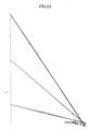
- FIG. 9 is a diagram illustrating a TV distortion for an example of a projection optical system according to an embodiment of the present invention.
- Dh denotes a TV distortion.
- h denotes a length from a center of an image to an edge of an image in a transverse direction of the image.
- ⁇ h denotes a distance between a straight line extending in a longitudinal direction of an image through an apex of the image and a straight line extending in a longitudinal direction of the image through an edge of the image in a transverse direction of the image.
- FIG. 10 is a diagram illustrating a TV distortion characteristic for a projection optical system in practical example 1 according to an embodiment of the present invention.
- a TV distortion for a projection optical system in practical example 1 is less than or equal to 2%.
- a distortion for a projection optical system in practical example 1 is corrected well.
- Table 5 illustrates the data of a projection optical system in practical example 2.
- a projection distance of a projection optical system and a size of an image projected on a screen are 295 mm and 60 inches, respectively, and hence, a throw ratio for a projection optical system in practical example 2 is 0.23.
- Table 6 illustrates coefficients of an aspheric surface for a projection optical system in practical example 2.
- Table 6 SURFACE NUMBER 3 4 20 21 22 23 4th ORDER COEFFICIENT (A) 2.48E-05 4.12E-05 5.34E-05 1.57E-08 -9.05E-05 -4.06E-05 6th ORDER COEFFICIENT (B) -1.24E-08 -1.55E-08 3.30E-06 6.62E-07 -6.39E-07 -6.27E-07 8th ORDER COEFFICIENT (C) 6.45E-10 7.35E-12 -1.20E-07 -1.55E-08 6.71E-09 1.10E-08 10th ORDER COEFFICIENT (D) -7.68E-13 2.71E-11 2.45E-09 1.82E-10 3.24E-12 -1.35E-10 12th ORDER COEFFICIENT (E) 2.12E-14 -6.21E-13 -2.74E-11 -1.11E
- Table 7 illustrates coefficients of a polynomial free-form surface for a projection optical system in practical example 2.
- Table 7 COEFFICIENT VALUE COEFFICIENT VALUE X2 -1.16E-03 X6Y3 -1.86E-15 Y2 2.93E-03 X4Y5 -1.36E-14 X2Y -4.21E-05 X2Y7 -7.82E-15 Y3 -9.02E-06 Y9 1.89E-14 X4 -1.15E-07 X10 3.48E-17 X2Y2 -3.60E-07 X8Y2 8.29E-17 Y4 5.38E-07 X6Y4 6.21E-17 X4Y -2.67E-09 X4Y6 3.62E-16 X2Y3 1.03E-09 X2Y8 2.65E-16 Y5 -1.18E-08 Y10 -1.42E-16 X6 1.31E-10 X10Y 6.40E-19
- Table 8 illustrates xfo and yfo for a projection optical system in practical example 2.
- Table 8 POSITION OF LIGHT RAY xfo yfo f1 112 0 110 0 f2 90 4 64 8 f3 61 8 17 4 f4 88 8 103 2 f5 84 4 53 6 f6 58 3 12 6 f7 50 6 82 4 f8 28 6 68 6 f9 50 3 2 0
- a projection distance for a projection optical system and a size of an image projected on a screen are 295 mm and 60 inches, respectively, and hence, a throw ratio Tr for a projection optical system in practical example 2 is 0.23.
- a length of an intermediate image in a direction of an optical axis of a first optical system for a projection optical system in practical example 2 is
- a focal length of a first optical system included in a projection optical system in practical example 2 is 27.53 mm.
- FIG. 11 is a diagram illustrating a projection optical system and an image projecting apparatus in practical example 2 according to an embodiment of the present invention.
- FIG. 11 illustrates an optical path for a projection optical system in practical example 2.
- FIG. 12 is a diagram illustrating a first optical system and a second optical system for a projection optical system in practical example 2 according to an embodiment of the present invention.
- FIG. 12 is an enlarged view of a first optical system and a second optical system.
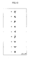
- FIG. 13 is a diagram illustrating a spot on a surface to be projected on for a projection optical system in practical example 2 according to an embodiment of the present invention.
- FIG. 13 illustrates a spot diagram corresponding to lattice points f1 - f9 on an image forming part included in an image projecting apparatus in practical example 2. As illustrated in FIG. 13 , a spot on a screen in practical example 2 is focused well.
- FIG. 14 is a diagram illustrating a TV distortion characteristic for a projection optical system in practical example 2 according to an embodiment of the present invention.
- a TV distortion for a projection optical system in practical example 2 is less than or equal to 2%.
- a distortion for a projection optical system in practical example 2 is corrected well.
- Table 9 illustrates the data of a projection optical system in practical example 3.
- a projection distance of a projection optical system and a size of an image projected on a screen are 388 mm and 60 inches, respectively, and hence, a throw ratio for a projection optical system in practical example 3 is 0.30.
- Table 10 illustrates coefficients of an aspheric surface for a projection optical system in practical example 3.
- Table 10 SURFACE NUMBER 3 4 20 21 22 23 4th ORDER COEFFICIENT (A) 4 77E-05 4 88E-05 2 88E-05 8 18E-06 -1 01E-04 -7 57E-05 6th ORDER COEFFICIENT (B) -3 05E-08 -1 84E-08 3 05E-06 7 00E-07 -3 71E-07 -5 65E-07 8th ORDER COEFFICIENT (C) 4 70E-10 -1 20E-10 -1 20E-07 -1 76E-08 6 32E-09 1 22E-08 10th ORDER COEFFICIENT (D) 5 49E-13 2 74E-11 2 38E-09 1 59E-10 1 79E-12 -1 32E-10 12th ORDER COEFFICIENT (E) 3 91E-14 -6 03E-13 -2 79E-11 -1 20
- Table 11 illustrates coefficients of a polynomial free-form surface for a projection optical system in practical example 3.
- Table 11 COEFFICIENT VALUE COEFFICIENT VALUE X2 -4.44E-03 X6Y3 -4.55E-14 Y2 1.49E-03 X4Y5 1.29E-13 X2Y -1.65E-04 X2Y7 1.07E-14 Y3 -4.61E-05 Y9 3.95E-14 X4 8.73E-09 X10 -2.71E-16 X2Y2 -3.07E-06 X8Y2 3.95E-16 Y4 -3.86E-07 X6Y4 -1.55E-15 X4Y 1.59E-08 X4Y6 1.10E-15 X2Y3 -7.19E-08 X2Y8 5.02E-15 Y5 -2.00E-08 Y10 -9.56E-15 X6 -3.03E-11 X10Y -1.04
- Table 12 illustrates xfo and yfo for a projection optical system in practical example 3.
- Table 12 POSITION OF LIGHT RAY xfo yfo f1 86.6 85.9 f2 74.8 61.5 f3 55.9 26.2 f4 75.0 81.9 f5 70.9 54.2 f6 53.3 21.2 f7 51.4 69.3 f8 35.6 60.6 f9 46.5 8.6
- a projection distance for a projection optical system and a size of an image projected on a screen are 388 mm and 60 inches, respectively, and hence, a throw ratio Tr for a projection optical system in practical example 3 is 0.30.
- a length of an intermediate image in a direction of an optical axis of a first optical system for a projection optical system in practical example 3 is
- a focal length of a first optical system included in a projection optical system in practical example 3 is 31.34 mm.
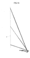
- FIG. 15 is a diagram illustrating a projection optical system and an image projecting apparatus in practical example 3 according to an embodiment of the present invention.
- FIG. 15 illustrates an optical path for a projection optical system in practical example 3.
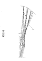
- FIG. 16 is a diagram illustrating a first optical system and a second optical system for a projection optical system in practical example 3 according to an embodiment of the present invention.
- FIG. 16 is an enlarged view of a first optical system and a second optical system.
- FIG. 17 is a diagram illustrating a spot on a surface to be projected on for a projection optical system in practical example 3 according to an embodiment of the present invention.
- FIG. 17 illustrates a spot diagram corresponding to lattice points f1 ⁇ f9 on an image forming part included in an image projecting apparatus in practical example 3. As illustrated in FIG. 17 , a spot on a screen in practical example 3 is focused well.
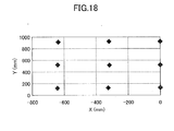
- FIG. 18 is a diagram illustrating a TV distortion characteristic for a projection optical system in practical example 3 according to an embodiment of the present invention.
- a TV distortion for a projection optical system in practical example 3 is less than or equal to 2%.
- a distortion for a projection optical system in practical example 3 is corrected well.
- Table 13 illustrates the data of a projection optical system in practical example 4.
- a projection distance of a projection optical system and a size of an image projected on a screen are 517 mm and 60 inches, respectively, and hence, a throw ratio for a projection optical system in practical example 4 is 0.40.
- Table 14 illustrates coefficients of an aspheric surface for a projection optical system in practical example 4.
- Table 14 SURFACE NUMBER 3 4 20 21 22 23 4th ORDER COEFFICIENT (A) 2. 76E-05 4. 40E-05 4. 30E-05 8. 27E-06 -1. 03E-04 -7. 45E-05 6th ORDER COEFFICIENT (B) -6. 90E-09 -2. 05E-08 2. 77E-06 6. 23E-07 -5. 08E-07 -6. 61E-07 8th ORDER COEFFICIENT (C) 5. 29E-10 -1. 15E-10 -1. 18E-07 -1. 49E-08 6. 43E-09 1.
- Table 15 illustrates coefficients of a polynomial free-form surface for a projection optical system in practical example 4.
- Table 15 COEFFICIENT VALUE COEFFICIENT VALUE X2 -1.74E-03 X6Y3 -1.84E-14 Y2 2.72 E-03 X4Y5 -2.34E-14 X2Y -9.20E-05 X2Y7 -1.22E-14 Y3 -1.14E-05 Y9 1.81E-14 X4 -8.68E-08 X10 -1.30E-16 X2Y2 -1.02E-07 X8Y2 1.09E-15 Y4 -2.02E-07 X6Y4 4.44E-16 X4Y 7.12E-09 X4Y6 -2.96E-16 X2Y3 -4.63E-08 X2Y8 2.05E-16 Y5 -1.10E-08 Y10 -1.48E-16 X6 2.92E-10 X
- Table 16 illustrates xfo and yfo for a projection optical system in practical example 4.
- Table 16 POSITION OF LIGHT RAY xfo yfo f1 91 5 90 9 f2 82 1 72 2 f3 66 5 44 3 f4 83 3 88 0 f5 79 0 66 6 f6 64 3 39 8 f7 64 9 78 1 f8 52 4 70 7 f9 58 4 27 6
- a projection distance for a projection optical system and a size of an image projected on a screen are 517 mm and 60 inches, respectively, and hence, a throw ratio Tr for a projection optical system in practical example 4 is 0.40.
- a length of an intermediate image in a direction of an optical axis of a first optical system for a projection optical system in practical example 4 is
- a focal length of a first optical system included in a projection optical system in practical example 4 is 33.32 mm.
- FIG. 19 is a diagram illustrating a projection optical system and an image projecting apparatus in practical example 4 according to an embodiment of the present invention.
- FIG. 19 illustrates an optical path for a projection optical system in practical example 4.
- FIG. 20 is a diagram illustrating a first optical system and a second optical system for a projection optical system in practical example 4 according to an embodiment of the present invention.
- FIG. 20 is an enlarged view of a first optical system and a second optical system.
- FIG. 21 is a diagram illustrating a spot on a surface to be projected on for a projection optical system in practical example 4 according to an embodiment of the present invention.
- FIG. 21 illustrates a spot diagram corresponding to lattice points f1 - f9 on an image forming part included in an image projecting apparatus in practical example 4. As illustrated in FIG. 24 , a spot on a screen in practical example 4 is focused well.
- FIG. 22 is a diagram illustrating a TV distortion characteristic for a projection optical system in practical example 4 according to an embodiment of the present invention.
- a TV distortion for a projection optical system in practical example 4 is less than or equal to 2%.
- a distortion for a projection optical system in practical example 4 is corrected well.
- Table 17 illustrates the data of a projection optical system in practical example 5.
- a projection distance of a projection optical system and a size of an image projected on a screen are 672 mm and 60 inches, respectively, and hence, a throw ratio for a projection optical system in practical example 5 is 0.52.
- Table 18 illustrates coefficients of an aspheric surface for a projection optical system in practical example 5.
- Table 18 SURFACE NUMBER 3 4 20 21 22 23 4th ORDER COEFFICIENT (A) 2. 26E-05 4. 73E-05 2. 86E-05 -2. 89E-06 -1. 06E-04 -7. 80E-05 6th ORDER COEFFICIENT (B) 2. 35E-08 8. 14E-09 2. 62E-06 5. 41E-07 -4. 79E-07 -6. 18E-07 8th ORDER COEFFICIENT (C) 5. 19E-10 2. 09E-10 -1. 16E-07 -1. 50E-08 6. 54E-09 1.
- Table 19 illustrates coefficients of a polynomial free-form surface for a projection optical system in practical example 5.
- Table 19 COEFFICIENT VALUE COEFFICIENT VALUE X2 -3.59E-03 X6Y3 7.64E-14 Y2 6.17E-05 X4Y5 1.25E-13 X2Y -1.60E-04 X2Y7 1.55E-13 Y3 -8.37E-05 Y9 -4.66E-14 X4 8.02E-07 X10 -1.16E-15 X2Y2 -2.47E-06 X8Y2 2.68E-15 Y4 -1.81E-06 X6Y4 2.20E-15 X4Y 6.60E-08 X4Y6 -4.68E-15 X2Y3 -3.61E-08 X2Y8 4.00E-14 Y5 -4.08E-08 Y10 -8.45E-15 X6 -1.43E-10 X10Y -1.
- Table 20 illustrates xfo and yfo for a projection optical system in practical example 5.
- Table 20 POSITION OF LIGHT RAY xfo yfo f1 75 7 75 3 f2 69 0 62 4 f3 57 4 43 1 f4 70 2 73 2 f5 66 7 58 6 f6 55 7 39 8 f7 57 7 66 2 f8 48 9 60 6 f9 51 0 30 8
- a projection distance for a projection optical system and a size of an image projected on a screen are 672 mm and 60 inches, respectively, and hence, a throw ratio Tr for a projection optical system in practical example 5 is 0.52.
- a length of an intermediate image in a direction of an optical axis of a first optical system for a projection optical system in practical example 5 is
- a focal length of a first optical system included in a projection optical system in practical example 5 is 33.91 mm.
- FIG. 23 is a diagram illustrating a projection optical system and an image projecting apparatus in practical example 5 according to an embodiment of the present invention.
- FIG. 23 illustrates an optical path for a projection optical system in practical example 5.
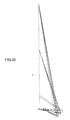
- FIG. 24 is a diagram illustrating a first optical system and a second optical system for a projection optical system in practical example 5 according to an embodiment of the present invention.
- FIG. 24 is an enlarged view of a first optical system and a second optical system.
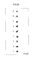
- FIG. 25 is a diagram illustrating a spot on a surface to be projected on for a projection optical system in practical example 5 according to an embodiment of the present invention.
- FIG. 25 illustrates a spot diagram corresponding to lattice points f1 - f9 on an image forming part included in an image projecting apparatus in practical example 5. As illustrated in FIG. 25 , a spot on a screen in practical example 5 is focused well.
- FIG. 26 is a diagram illustrating a TV distortion characteristic for a projection optical system in practical example 5 according to an embodiment of the present invention.
- a TV distortion for a projection optical system in practical example 5 is less than or equal to 2%.
- a distortion for a projection optical system in practical example 5 is corrected well.
- Table 21 illustrates the data of a projection optical system in practical example 6.
- a projection distance of a projection optical system and a size of an image projected on a screen are 775 mm and 60 inches, respectively, and hence, a throw ratio for a projection optical system in practical example 6 is 0.60.
- Table 22 illustrates coefficients of an aspheric surface for a projection optical system in practical example 6.
- Table 22 SURFACE NUMBER 3 4 20 21 22 23 4th ORDER COEFFICIENT (A) 2. 16E-05 5. 17E-05 3. 98E-05 -4. 80E-06 -1. 08E-04 -7. 83E-05 6th ORDER COEFFICIENT (B) 2. 78E-08 1. 86E-08 2. 55E-06 5. 27E-07 -4. 79E-07 -5. 97E-07 8th ORDER COEFFICIENT (C) 2. 84E-10 1. 69E-10 -1. 14E-07 -1. 47E-08 6. 37E-09 1.
- Table 23 illustrates coefficients of a polynomial free-form surface for a projection optical system in practical example 6.
- Table 24 illustrates xfo and yfo for a projection optical system in practical example 6.
- Table 24 POSITION OF LIGHT RAY xfo yfo f1 72 2 71 9 f2 66 4 60 8 f3 56 2 44 1 f4 67 7 70 2 f5 64 4 57 6 f6 54 7 41 3 f7 57 0 64 1 f8 49 2 59 1 f9 50 6 33 3
- a projection distance for a projection optical system and a size of an image projected on a screen are 775 mm and 60 inches, respectively, and hence, a throw ratio Tr for a projection optical system in practical example 6 is 0.60.
- a length of an intermediate image in a direction of an optical axis of a first optical system for a projection optical system in practical example 6 is
- a focal length of a first optical system included in a projection optical system in practical example 6 is 35.74 mm.
- FIG. 27 is a diagram illustrating a projection optical system and an image projecting apparatus in practical example 6 according to an embodiment of the present invention.
- FIG. 27 illustrates an optical path for a projection optical system in practical example 6.
- FIG. 28 is a diagram illustrating a first optical system and a second optical system for a projection optical system in practical example 6 according to an embodiment of the present invention.
- FIG. 28 is an enlarged view of a first optical system and a second optical system.
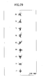
- FIG. 29 is a diagram illustrating a spot on a surface to be projected on for a projection optical system in practical example 6 according to an embodiment of the present invention.
- FIG. 29 illustrates a spot diagram corresponding to lattice points f1 - f9 on an image forming part included in an image projecting apparatus in practical example 6. As illustrated in FIG. 29 , a spot on a screen in practical example 6 is focused well.
- FIG. 30 is a diagram illustrating a TV distortion characteristic for a projection optical system in practical example 6 according to an embodiment of the present invention.
- a TV distortion for a projection optical system in practical example 6 is less than or equal to 2%.
- a distortion for a projection optical system in practical example 6 is corrected well.
- Table 25 illustrates the data of a projection optical system in practical example 7.
- a projection distance of a projection optical system and a size of an image projected on a screen are 795 mm and 60 inches, respectively, and hence, a throw ratio for a projection optical system in practical example 7 is 0.62.
- Table 26 illustrates coefficients of an aspheric surface for a projection optical system in practical example 7.
- Table 26 SURFACE NUMBER 3 4 20 21 22 23 4th ORDER COEFFICIENT (A) 1. 20E-05 4. 38E-05 3. 91E-05 1. 66E-05 -9. 47E-05 -5. 66E-05 6th ORDER COEFFICIENT (B) 1. 71E-08 4. 99E-09 3. 34E-06 7. 40E-07 -5. 27E-07 -6. 35E-07 8th ORDER COEFFICIENT (C) 6. 61E-10 2. 26E-10 -1. 20E-07 -1. 51E-08 6. 53E-09 1.
- Table 27 illustrates coefficients of a polynomial free-form surface for a projection optical system in practical example 7.
- Table 27 COEFFICIENT VALUE COEFFICIENT VALUE X2 2.48E-04 X6Y3 -1.79E-15 Y2 2.44E-03 X4Y5 -1.62E-14 X2Y -2.87E-05 X2Y7 -9.16E-15 Y3 -1.65E-05 Y9 1.90E-14 X4 4.62E-08 X10 3.83E-17 X2Y2 1.58E-07 X8Y2 5.33E-17 Y4 5.31E-07 X6Y4 1.21E-16 X4Y 6.85E-10 X4Y6 3.81E-16 X2Y3 5.71E-10 X2Y8 2.36E-16 Y5 -1.28E-08 Y10 -1.45E-16 X6 9.70E-11 X10Y -1.04E-20 X4Y2 -8.13
- Table 28 illustrates xfo and yfo for a projection optical system in practical example 7.
- Table 28 POSITION OF LIGHT RAY xfo yfo f1 100 0 100 2 f2 90 2 81 7 f3 72 6 51 0 f4 92 8 96 7 f5 86 8 76 0 f6 70 1 46 1 f7 74 5 85 9 f8 60 4 77 5 f9 63 1 32 4
- a projection distance for a projection optical system and a size of an image projected on a screen are 795 mm and 60 inches, respectively, and hence, a throw ratio Tr for a projection optical system in practical example 7 is 0.62.
- a length of an intermediate image in a direction of an optical axis of a first optical system for a projection optical system in practical example 7 is -xfo of f1 - yfo of f9
- a focal length of a first optical system included in a projection optical system in practical example 7 is 28.56 mm.
- FIG. 31 is a diagram illustrating a projection optical system and an image projecting apparatus in practical example 7 according to an embodiment of the present invention.
- FIG. 31 illustrates an optical path for a projection optical system in practical example 7.
- FIG. 32 is a diagram illustrating a first optical system and a second optical system for a projection optical system in practical example 7 according to an embodiment of the present invention.
- FIG. 32 is an enlarged view of a first optical system and a second optical system.
- FIG. 33 is a diagram illustrating a spot on a surface to be projected on for a projection optical system in practical example 7 according to an embodiment of the present invention.
- FIG. 33 illustrates a spot diagram corresponding to lattice points f1 - f9 on an image forming part included in an image projecting apparatus in practical example 7. As illustrated in FIG. 33 , a spot on a screen in practical example 7 is focused well.
- FIG. 34 is a diagram illustrating a TV distortion characteristic for a projection optical system in practical example 7 according to an embodiment of the present invention.
- a TV distortion for a projection optical system in practical example 7 is less than or equal to 2%.
- a distortion for a projection optical system in practical example 7 is corrected well.
- Table 29 illustrates the data of a projection optical system in practical example 8.
- a projection distance of a projection optical system and a size of an image projected on a screen are 200 mm and 60 inches, respectively, and hence, a throw ratio for a projection optical system in practical example 8 is 0.15.
- Table 30 illustrates coefficients of an aspheric surface for a projection optical system in practical example 8.
- Table 30 SURFACE NUMBER 3 4 16 17 18 19 4th ORDER COEFFICIENT (A) 2. 75E-04 2. 76E-04 1. 83E-04 6. 41E-05 -1. 48E-04 -5. 30E-05 6th ORDER COEFFICIENT (B) 6. 38E-06 7. 00E-06 3. 48E-06 1. 53E-06 -7. 50E-07 -5. 39E-07 8th ORDER COEFFICIENT (C) 1. 13E-07 1. 88E-07 -1. 12E-07 -1. 78E-08 1. 00E-08 7. 45E-09 10th ORDER COEFFICIENT (D) 6.
- Table 31 illustrates coefficients of a polynomial free-form surface for a projection optical system in practical example 8.
- Table 31 COEFFICIENT VALUE COEFFICIENT VALUE X2 -5.33E-04 X6Y3 1.10E-15 Y2 3.64E-03 X4Y5 -1.37E-14 X2Y -3.83E-05 X2Y7 -2.04E-14 Y3 -2.35E-06 Y9 1.87E-14 X4 -3.42E-10 X10 1.44E-17 X2Y2 -1.87E-07 X8Y2 4.27E-17 Y4 3.66E-07 X6Y4 -4.42E-17 X4Y -2.30E-09 X4Y6 2.33E-16 X2Y3 1.43E-10 X2Y8 5.07E-16 Y5 -4.55E-09 Y10 -1.44E-16 X6 5.36E-11 X10Y 5.46E-20 X4
- Table 32 illustrates xfo and yfo for a projection optical system in practical example 8.
- Table 32 POSITION OF LIGHT RAY xfo yfo f1 123 9 120 4 f2 93 4 55 4 f3 58 1 3 9 f4 86 2 109 2 f5 85 7 39 9 f6 54 4 0 3 f7 33 6 81 8 f8 12 1 64 9 f9 47 4 -6 9
- a projection distance for a projection optical system and a size of an image projected on a screen are 200 mm and 60 inches, respectively, and hence, a throw ratio Tr for a projection optical system in practical example 8 is 0.15.
- a length of an intermediate image in a direction of an optical axis of a first optical system for a projection optical system in practical example 8 is
- a focal length of a first optical system included in a projection optical system in practical example 8 is 25.09 mm.
- FIG. 35 is a diagram illustrating a projection optical system and an image projecting apparatus in practical example 8 according to an embodiment of the present invention.
- FIG. 35 illustrates an optical path for a projection optical system in practical example 8.
- FIG. 36 is a diagram illustrating a first optical system and a second optical system for a projection optical system in practical example 8 according to an embodiment of the present invention.
- FIG. 36 is an enlarged view of a first optical system and a second optical system.
- a first optical system included in a projection optical system is composed of nine lenses and a stop but the number of a lens(es) composing a lens element in a first optical system included in a projection optical system is not necessarily needed to be nine. Also, a position of a stop in a first optical system included in a projection optical system is not necessarily needed to be a position illustrated in FIG. 36 .
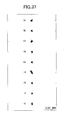
- FIG. 37 is a diagram illustrating a spot on a surface to be projected on for a projection optical system in practical example 8 according to an embodiment of the present invention.
- FIG. 37 illustrates a spot diagram corresponding to lattice points f1 - f9 on an image forming part included in an image projecting apparatus in practical example 8. As illustrated in FIG. 37 , a spot on a screen in practical example 8 is focused well.
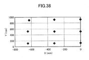
- FIG. 38 is a diagram illustrating a TV distortion characteristic for a projection optical system in practical example 8 according to an embodiment of the present invention.
- a TV distortion for a projection optical system in practical example 8 is less than or equal to 3%.
- a distortion for a projection optical system in practical example 8 is corrected well.
- Table 33 illustrates the data of a projection optical system in practical example 9.
- a projection distance of a projection optical system and a size of an image projected on a screen are 226.5 mm and 60 inches, respectively, and hence, a throw ratio for a projection optical system in practical example 9 is 0.18.
- Table 34 illustrates coefficients of an aspheric surface for a projection optical system in practical example 9.
- Table 34 SURFACE NUMBER 3 4 16 17 18 19 4th ORDER COEFFICIENT (A) 3. 07E-04 2. 35E-04 1. 65E-04 7. 84E-05 -1. 07E-04 -4. 82E-05 6th ORDER COEFFICIENT (B) 3. 30E-06 3. 20E-06 3. 88E-06 1. 43E-06 -4. 76E-07 -4. 68E-07 8th ORDER COEFFICIENT (C) 5. 82E-08 1. 16E-07 -1. 11E-07 -1. 70E-08 1. 05E-08 7. 09E-09 10th ORDER COEFFICIENT (D) 5.
- Table 35 illustrates coefficients of a polynomial free-form surface for a projection optical system in practical example 9.
- Table 35 COEFFICIENT VALUE COEFFICIENT VALUE X2 -1.37E-03 X6Y3 1.83E-15 Y2 3.46E-03 X4Y5 -1.78E-14 X2Y -5.53E-05 X2Y7 -2.37E-14 Y3 -5.02E-06 Y9 1.92E-14 X4 -5.30E-08 X10 2.02E-17 X2Y2 -5.16E-07 X8Y2 5.53E-17 Y4 3.09E-07 X6Y4 -6.96E-17 X4Y -3.79E-09 X4Y6 4.37E-16 X2Y3 -4.29E-09 X2Y8 6.00E-16 Y5 -4.03E-09 Y10 -1.43E-16 X6 4.22E-11 X10Y -4
- Table 36 illustrates xfo and yfo for a projection optical system in practical example 6.
- Table 32 POSITION OF LIGHT RAY xfo yfo f1 113 8 111 2 f2 89 7 60 0 f3 59 5 10 3 f4 85 3 102 5 f5 83 0 46 7 f6 56 1 6 0 f7 40 9 79 6 f8 19 5 65 7 f9 48 5 -2 6
- a projection distance for a projection optical system and a size of an image projected on a screen are 226.5 mm and 60 inches, respectively, and hence, a throw ratio Tr for a projection optical system in practical example 9 is 0.18.
- a length of an intermediate image in a direction of an optical axis of a first optical system for a projection optical system in practical example 9 is
- a focal length of a first optical system included in a projection optical system in practical example 9 is 25.57 mm.
- FIG. 39 is a diagram illustrating a projection optical system and an image projecting apparatus in practical example 9 according to an embodiment of the present invention.
- FIG. 39 illustrates an optical path for a projection optical system in practical example 9.
- FIG. 40 is a diagram illustrating a first optical system and a second optical system for a projection optical system in practical example 9 according to an embodiment of the present invention.
- FIG. 40 is an enlarged view of a first optical system and a second optical system.
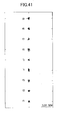
- FIG. 41 is a diagram illustrating a spot on a surface to be projected on for a projection optical system in practical example 9 according to an embodiment of the present invention.
- FIG. 41 illustrates a spot diagram corresponding to lattice points f1 - f9 on an image forming part included in an image projecting apparatus in practical example 9. As illustrated in FIG. 41 , a spot on a screen in practical example 9 is focused well.
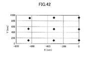
- FIG. 42 is a diagram illustrating a TV distortion characteristic for a projection optical system in practical example 9 according to an embodiment of the present invention.
- a TV distortion for a projection optical system in practical example 9 is less than or equal to 3%.
- a distortion for a projection optical system in practical example 9 is corrected well.
- Table 37 illustrates the data of a projection optical system in practical example 10.
- a projection distance of a projection optical system and a size of an image projected on a screen are 795 mm and 60 inches, respectively, and hence, a throw ratio for a projection optical system in practical example 10 is 0.62.
- Table 38 illustrates coefficients of an aspheric surface for a projection optical system in practical example 10.
- Table 38 SURFACE NUMBER 3 4 20 21 22 23 4th ORDER COEFFICIENT (A) 2. 16E-05 4. 65E-05 6. 97E-05 1. 25E-05 -9. 26E-05 -5. 16E-05 6th ORDER COEFFICIENT (B) 3. 56E-08 -2. 25E-08 3. 19E-06 7. 98E-07 -4. 84E-07 -6. 53E-07 8th ORDER COEFFICIENT (C) 4. 45E-10 -5. 12E-11 -1. 17E-07 -1. 48E-08 6. 53E-09 1.
- Table 39 illustrates coefficients of a polynomial free-form surface for a projection optical system in practical example 10.
- Table 39 COEFFICIENT VALUE COEFFICIENT VALUE X2 9.83E-04 X6Y3 -1.99E-15 Y2 2.89E-03 X4Y5 -1.64E-14 X2Y -2.14E-05 X2Y7 -9.17E-15 Y3 -1.36E-05 Y9 1.90E-14 X4 1.13E-07 X10 3.58E-17 X2Y2 2.58E-07 X8Y2 3.46E-17 Y4 4.78E-07 X6Y4 1.30E-16 X4Y -1.78E-09 X4Y6 3.79E-16 X2Y3 1.53E-09 X2Y8 2.27E-16 Y5 -1.15E-08 Y10 -1.44E-16 X6 1.02E-10 X10Y 7.08E-20 X4Y2 -3.
- Table 40 illustrates xfo and yfo for a projection optical system in practical example 10.
- Table 40 POSITION OF LIGHT RAY xfo yfo f1 200 7 201 3 f2 190 0 181 8 f3 166 8 134 4 f4 195 0 197 3 f5 185 7 174 4 f6 163 2 126 2 f7 171 6 184 2 f8 149 1 173 4 f9 152 8 101 2
- a projection distance for a projection optical system and a size of an image projected on a screen are 795 mm and 60 inches, respectively, and hence, a throw ratio Tr for a projection optical system in practical example 10 is 0.62.
- a length of an intermediate image in a direction of an optical axis of a first optical system for a projection optical system in practical example 10 is
- a focal length of a first optical system included in a projection optical system in practical example 10 is 39.30 mm.
- FIG. 43 is a diagram illustrating a projection optical system and an image projecting apparatus in practical example 10 according to an embodiment of the present invention.
- FIG. 43 illustrates an optical path for a projection optical system in practical example 10.
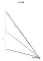
- FIG. 44 is a diagram illustrating a first optical system and a second optical system for a projection optical system in practical example 10 according to an embodiment of the present invention.
- FIG. 44 is an enlarged view of a first optical system and a second optical system.
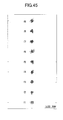
- FIG. 45 is a diagram illustrating a spot on a surface to be projected on for a projection optical system in practical example 10 according to an embodiment of the present invention.
- FIG. 45 illustrates a spot diagram corresponding to lattice points f1 - f9 on an image forming part included in an image projecting apparatus in practical example 10. As illustrated in FIG. 45 , a spot on a screen in practical example 10 is focused well.
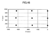
- FIG. 46 is a diagram illustrating a TV distortion characteristic for a projection optical system in practical example 10 according to an embodiment of the present invention.
- a TV distortion for a projection optical system in practical example 10 is less than or equal to 3%.
- a distortion for a projection optical system in practical example 10 is corrected well.
- Table 41 illustrates the data of a projection optical system in practical example 11.
- a projection distance of a projection optical system and a size of an image projected on a screen are 775 mm and 60 inches, respectively, and hence, a throw ratio for a projection optical system in practical example 11 is 0.60.
- Table 42 illustrates coefficients of an aspheric surface for a projection optical system in practical example 11.
- Table 42 SURFACE NUMBER 3 4 20 21 22 23 4th ORDER COEFFICIENT (A) 1. 10E-05 4. 83E-05 4. 80E-05 -6. 60E-07 -1. 10E-04 -8. 75E-05 6th ORDER COEFFICIENT (B) -8. 76E-10 -1. 13E-08 2. 48E-06 5. 23E-07 -4. 85E-07 -5. 94E-07 8th ORDER COEFFICIENT (C) 2. 62E-11 2. 04E-11 -1. 13E-07 -1. 43E-08 6. 05E-09 1.
- Table 43 illustrates coefficients of a polynomial free-form surface for a projection optical system in practical example 11.
- Table 43 COEFFICIENT VALUE COEFFICIENT VALUE X2 -5.03E-03 X6Y3 1.01E-13 Y2 -3.81E-03 X4Y5 -2.04E-13 X2Y -1.43E-04 X2Y7 1.30E-12 Y3 -1.13E-04 Y9 -8.22E-13 X4 2.73E-06 X10 -7.52E-15 X2Y2 1.69E-06 X8Y2 1.32E-16 Y4 -1.54E-07 X6Y4 1.29E-14 X4Y 1.24E-07 X4Y6 2.80E-16 X2Y3 1.40E-07 X2Y8 -4.90E-14 Y5 -7.14E-08 Y10 5.51E-14 X6 -2.36E-09 X10Y -3.90E
- Table 44 illustrates xfo and yfo for a projection optical system in practical example 11.
- Table 44 POSITION OF LIGHT RAY xfo yfo f1 71 2 70 7 f2 65 6 60 7 f3 56 5 48 4 f4 66 9 69 2 f5 63 9 58 0 f6 55 3 47 0 f7 57 9 63 8 f8 51 6 59 2 f9 52 0 42 3
- a projection distance for a projection optical system and a size of an image projected on a screen are 775 mm and 60 inches, respectively, and hence, a throw ratio Tr for a projection optical system in practical example 11 is 0.60.
- a focal length of a first optical system included in a projection optical system in practical example 11 is 35.59 mm.
- FIG. 47 is a diagram illustrating a projection optical system and an image projecting apparatus in practical example 11 according to an embodiment of the present invention.
- FIG. 47 illustrates an optical path for a projection optical system in practical example 11.
- FIG. 48 is a diagram illustrating a first optical system and a second optical system for a projection optical system in practical example 11 according to an embodiment of the present invention.
- FIG. 48 is an enlarged view of a first optical system and a second optical system.
- FIG. 49 is a diagram illustrating a spot on a surface to be projected on for a projection optical system in practical example 11 according to an embodiment of the present invention.
- FIG. 49 illustrates a spot diagram corresponding to lattice points f1 - f9 on an image forming part included in an image projecting apparatus in practical example 11.
- a spot on a screen in practical example 11 is generally well focused.
- a value of a white Modulation Transfer Function (MTF) with respect to a frequency in a WXGA resolution is greater than or equal to 35% over an entire area of an image projected on a screen.
- MTF white Modulation Transfer Function
- a spot on a screen in any of practical examples 1 - 10 is focused better than a spot on a screen in practical example 11. Furthermore, a value of a white MTF with respect to a frequency in a WXGA resolution in any of practical examples 1 - 10 is higher than a value of a white MTF with respect to a frequency in a WXGA resolution in practical example 11.
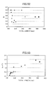
- FIG. 50 is a diagram illustrating a TV distortion characteristic for a projection optical system in practical example 11 according to an embodiment of the present invention.
- a TV distortion for a projection optical system in practical example 11 is less than or equal to approximately 5%.
- a distortion for a projection optical system in practical example 11 is generally well corrected.
- a distortion for a projection optical system in any of practical examples 1 - 10 is smaller than a distortion for a projection optical system in practical example 11.
- Table 45 illustrates xfo and yfo for a projection optical system in comparative example 1.
- Table 45 POSITION OF LIGHT RAY xfo yfo f1 230 6 189 1 f2 187 0 104 0 f3 141 2 38 4 f4 222 0 169 5 f5 180 5 92 8 f6 137 2 32 8 f7 122 3 196 6 f8 163 3 64 6 f9 126 9 18 4
- a projection distance for a projection optical system and a size of an image projected on a screen are 416 mm and 52.7 inches, respectively, and hence, a throw ratio Tr for a projection optical system in comparative example 1 is 0.36.
- a length of an intermediate image in a direction of an optical axis of a first optical system for a projection optical system in comparative example 1 is
- a focal length of a first optical system included in a projection optical system in comparative example 1 is 35.87 mm.
- Table 46 illustrates xfo and yfo for a projection optical system in comparative example 2.
- Table 46 POSITION OF LIGHT RAY xfo yfo f1 227 9 203 2 f2 185 4 119 2 f3 138 5 44 2 f4 217 5 180 3 f5 177 5 104 8 f6 133 9 36 6 f7 125 3 188 3 f8 157 3 69 2 f9 122 0 16 2
- a projection distance for a projection optical system and a size of an image projected on a screen are 501 mm and 63.4 inches, respectively, and hence, a throw ratio Tr for a projection optical system in comparative example 2 is 0.36.
- a length of an intermediate image in a direction of an optical axis of a first optical system for a projection optical system in comparative example 2 is
- a focal length of a first optical system included in a projection optical system in comparative example 2 is 32.91 mm.
- Table 47 illustrates xfo and yfo for a projection optical system in comparative example 3.
- a projection distance for a projection optical system and a size of an image projected on a screen are 440 mm and 60 inches, respectively, and hence, a throw ratio Tr for a projection optical system in comparative example 3 is 0.36.
- a length of an intermediate image in a direction of an optical axis of a first optical system for a projection optical system in comparative example 3 is
- a focal length of a first optical system included in a projection optical system in comparative example 3 is 26.4 mm.
- Table 48 illustrates throw ratios Tr, total lengths, and values of Im ⁇ Tr for projection optical systems in practical examples 1 - 11 and projection optical systems in comparative examples 1 - 3.
- Table 48 Tr TOTAL LENGTH Im ⁇ Tr PRACTICAL EXAMPLE 1 0 18 256 0 90 PRACTICAL EXAMPLE 2 0 23 236 0 92 PRACTICAL EXAMPLE 3 0 30 200 0 75 PRACTICAL EXAMPLE 4 0 40 207 0 77 PRACTICAL EXAMPLE 5 0 52 192 0 69 PRACTICAL EXAMPLE 6 0 60 190 0 65 PRACTICAL EXAMPLE 7 0 62 237 1 47 PRACTICAL EXAMPLE 8 0 15 224 0 83 PRACTICAL EXAMPLE 9 0 18 201 0 82 PRACTICAL EXAMPLE 10 0 62 339 1 58 PRACTICAL EXAMPLE 11 0 60 186 0 49 COMPARATIVE EXAMPLE 1 0 36 575 2 13
- any ofprojection optical systems in practical examples 1 - 11 and projection optical systems in comparative examples 1 - 3 satisfies a throw ratio Tr ⁇ 0.7.
- any of projection optical systems in practical examples 1 - 11 and projection optical systems in comparative examples 1 - 3 provides a more compact projection optical system capable of projecting an image onto a surface to be projected on at a shorter distance.
- Im means a normalized length of an intermediate image in a direction of an optical axis of a first optical system.
- a value of Im ⁇ Tr (0.77) for a projection optical system in practical example 4 is smaller than any of values of Im ⁇ Tr (2.13, 2.32, and 1.72) for projection optical systems in comparative examples 1 - 3.
- a value of Im for a projection optical system in practical example 4 is generally smaller than any of values of Im for projection optical systems in comparative examples 1 - 3, because a value of Tr for a projection optical system in practical example 4 is generally comparable to any of values of Tr for projection optical systems in comparative examples 1 - 3.
- a value of total length (207) for a projection optical system in practical example 4 is smaller than any of values of total length (575, 525, and 385) for projection optical systems in comparative examples 1 ⁇ 3. It may be possible to reduce a distance from a last end of a first optical system included in a projection optical system in practical example 4 to a last end of a second optical system therein, compared to a distance from a last end of a first optical system included in a projection optical system in any of comparative examples 1 - 3 to a last end of a second optical system therein, because a value of Im for a projection optical system in practical example 4 is generally smaller than any of values of Im for projection optical systems in comparative examples 1 - 3. As a result, a value of total length for a projection optical system in practical example 4 is smaller than a value of total length for a projection optical system in any of comparative examples 1 - 3.
- a normalized length Im of an intermediate image in a direction of an optical axis of a first optical system included in a projection optical system tends to increase.
- a projection distance of a projection optical system in any of comparative examples 1 - 3 is reduced, a normalized length Im of an intermediate image in a direction of an optical axis of a first optical system included in a projection optical system increases and a total length of a projection optical system increase.
- an image projecting apparatus including a projection optical system in any of comparative examples 1 - 3 increases, and hence, an image projecting apparatus including a projection optical system in any of comparative examples 1 - 3 provides a user with an image projecting apparatus with a relatively low usability in such a manner that an image projecting apparatus including a projection optical system in any of comparative examples 1 - 3 occupies more space and/or it is not easy to carry an image projecting apparatus including a projection optical system in any of comparative examples 1 - 3, etc.
- FIG. 51 is a diagram illustrating a relationship between a throw ratio and a normalized length of an intermediate image for an example of a projection optical system according to an embodiment of the present invention and an example of a projection optical system in a conventional technique.
- a symbol of diamond, a symbol of square, a symbol of circle, and a symbol of triangle denote a projection optical system in any of practical examples 1 - 11, a projection optical system in comparative example 1, a projection optical system in comparative example 2, and a projection optical system in comparative example 3, respectively.
- a throw ratio Tr for a projection optical system in any of practical examples 1 - 11 is reduced, a normalized length Im of an intermediate image in a direction of an optical axis of a first optical system included in a projection optical system in any of practical examples 1 - 11 tends to increase.
- FIG. 52 is a diagram illustrating a relationship between a total length of an optical system and a throw ratio for an example of a projection optical system according to an embodiment of the present invention and an example of a projection optical system in a conventional technique.
- a symbol of diamond, a symbol of square, a symbol of circle, and a symbol of triangle denote a projection optical system in any of practical examples 1 - 11, a projection optical system in comparative example 1, a projection optical system in comparative example 2, and a projection optical system in comparative example 3, respectively.
- a total length of a projection optical system is a distance from an object point on an object to a last end of a second optical system 3 in a direction of an optical axis of a first optical system 2 with respect to a principal light ray of a light beam nearest an optical axis of the first optical system included in a projection optical system.
- any of projection optical systems in practical examples 1 - 11 and projection optical systems in comparative examples 1 - 3 satisfies a throw ratio less than or equal to 0.7 as illustrated in FIG. 51 and FIG. 52
- a normalized length of an intermediate image in a direction of an optical axis of a first optical system included in a projection optical system in any of practical examples 1 ⁇ 11 is smaller than a normalized length of an intermediate image in a direction of an optical axis of a first optical system included in a projection optical system in any of comparative examples 1 - 3, and hence, a total length ( ⁇ about 200 mm) of a projection optical system in any of practical examples 1 - 11 is smaller than a total length of a projection optical system in any of comparative examples 1 - 3.
- FIG. 53 is a diagram illustrating a relationship between a total length of an optical system and a value of Im ⁇ Tr for an example of a projection optical system according to an embodiment of the present invention and an example of a projection optical system in a conventional technique.
- a symbol of diamond, a symbol of square, a symbol of circle, and a symbol of triangle denote a projection optical system in any of practical examples 1 - 11, a projection optical system in comparative example 1, a projection optical system in comparative example 2, and a projection optical system in comparative example 3, respectively.
- a total length of a projection optical system in any of practical examples 1 - 11 is smaller than a total length of a projection optical system in any of comparative examples 1 - 3 as illustrated in FIG. 53 . That is, a projection optical system in any of practical examples 1 - 11 is a more compact projection optical system capable of projecting an image onto a surface to be projected on at a shorter distance, compared to a projection optical system in any of comparative examples 1 - 3.
- a value of Im ⁇ Tr for a projection optical system in any of practical examples 1 - 11 is smaller than a value of Im ⁇ Tr for a projection optical system in any of comparative examples 1 - 3. More specifically, a value of Im ⁇ Tr for a projection optical system in any of practical examples 1 - 11 is less than or equal to 1.70 and a value of Im ⁇ Tr for a projection optical system in any of comparative examples 1 - 3 is greater than 1.70.
- a condition that a value of Im ⁇ Tr for a projection optical system is less than or equal to 1.70 is satisfied, like a projection optical system in any of practical examples 1 - 11, and thereby, it may be possible to provide a more compact projection optical system capable of projecting an image onto a surface to be projected on at a shorter distance.
- a value of Im ⁇ Tr for a projection optical system is greater than 1.70 like a projection optical system in any of comparative examples 1 - 3, a throw ratio Tr for a projection optical system or a normalized length Im of an intermediate image in a direction of an optical axis of a first optical system included in a projection optical system increases, and hence, it may be difficult to provide a more compact projection optical system capable of projecting an image onto a surface to be projected on at a shorter distance.
- a value of Im ⁇ Tr for a projection optical system is preferably less than or equal to 1.50 to provide a more compact projection optical system capable of projecting an image onto a surface to be projected on at a shorter distance.
- a value of Im ⁇ Tr for a projection optical system is less than or equal to 1.50, for example, it may be possible to further reduce a normalized length Im of an intermediate image in a direction of an optical axis of a first optical system included in a projection optical system and it may be possible to reduce a total length of a projection optical system. As a result, it may be possible to provide a more compact projection optical system.
- a value of a throw ratio Tr of a projection optical system in practical example 7 is generally comparable to a value of a throw ratio Tr of a projection optical system in practical example 10.
- a value of Im ⁇ Tr for a projection optical system in practical example 7 is less than or equal to 1.50
- a value of Im ⁇ Tr for a projection optical system in practical example 10 is greater than 1.50.
- a value of Im for a projection optical system in practical example 7 is smaller than a value of Im for a projection optical system in practical example 10.
- a total length of a projection optical system in practical example 7 is smaller than a total length of a projection optical system in practical example 10.
- a value of Im ⁇ Tr for a projection optical system is preferably greater than or equal to 0.50.
- a value of Im ⁇ Tr for a projection optical system is greater than or equal to 0.50, it may be possible to increase a throw ratio Tr for a projection optical system or increase a normalized length Im of an intermediate image in a direction of an optical axis of a first optical system included in a projection optical system.
- it may be possible to increase a throw ratio Tr for a projection optical system it may be possible to reduce an angle of incidence of a light ray incident on a screen. As a result, it may be possible to reduce an aberration of a light beam incident on a screen and it may be possible to project a better image onto a screen.
- a value of Im ⁇ Tr for a projection optical system in any of practical examples 1 - 10 is greater than or equal to 0.50
- a value of Im ⁇ Tr for a projection optical system in practical example 11 is less than 0.50.
- a quality of an image projected onto a screen by a projection optical system in any of practical examples 1 - 10 is higher than a quality of an image projected onto a screen by a projection optical system in practical example 11.
- a projection optical system in any of practical examples 1 - 10 satisfies a condition that a value of Im ⁇ Tr for a projection optical system is greater than or equal to 0.50, and thereby, it may be possible to reduce an aberration (for example, an astigmatic aberration, a distortion aberration, etc.) for a light beam to be projected by a projection optical system, compared to a projection optical system in practical example 11.
- an aberration for example, an astigmatic aberration, a distortion aberration, etc.
- Table 49 illustrates a Petzval sum for a first optical system included in a projection optical system in any of practical examples 1 - 11 and comparative examples 1 - 3.
- Table 49 PRACTICAL EXAMPLE 1 -0.01135 PRACTICAL EXAMPLE 2 -0.01849 PRACTICAL EXAMPLE 3 -0.02992 PRACTICAL EXAMPLE 4 -0.03027 PRACTICAL EXAMPLE 5 -0.03444 PRACTICAL EXAMPLE 6 -0.03656 PRACTICAL EXAMPLE 7 -0.02461 PRACTICAL EXAMPLE 8 -0.01206 PRACTICAL EXAMPLE 9 -0.01732 PRACTICAL EXAMPLE 10 -0.02216 PRACTICAL EXAMPLE 11 -0.03640 COMPARATIVE EXAMPLE 1 -0.00705 COMPARATIVE EXAMPLE 2 -0.00982 COMPARATIVE EXAMPLE 3 -0.01191
- s denotes a number of a refractive surface.
- ns denotes a refractive index at a s-th surface and ns-1 denotes a refractive index at a s-1-th surface.
- rs denotes a radius of curvature of a s-th surface.
- a projection optical system when a projection distance of a projection optical system is small and an angle of incidence of a light ray projected onto a surface to be projected on is large, an aberration such as an astigmatic aberration or a field curvature, etc., for a light beam projected onto the surface to be projected on is preferably corrected by a second optical system.
- a second optical system it is preferable to increase a cross-section of a light beam to be projected onto the surface to be projected on, in a second optical system.
- a sign of a Patzval sum of a first optical system included in a projection optical system according to an embodiment of the present invention is negative and an absolute value of a Petzval sum of a first optical system included in a projection optical system according to an embodiment of the present invention is large.
- a Petzval sum PTZ of a first optical system included in a projection optical system in any of practical examples 1 - 11 is less than or equal to - 0.01135.
- a Petzval sum PTZ of a first optical system included in a projection optical system is less than or equal to -0.01135, it may be possible to provide a projection optical system capable of projecting a better image onto a screen, such as a projection optical system in any of practical examples 1 - 11.
- a projection optical system with a fixed focal length is illustrated in any of practical examples 1 - 11, it may be possible to adjust a focal length of a projection optical system (or conduct adjustment of focusing for the projection optical system) due to movement of a first optical system or second optical system included in the projection optical system.
- At least one illustrative embodiment of the present invention may relate to a projection optical system and an image projecting apparatus.
- One object of at least one illustrative embodiment of the present invention may be to provide a more compact projection optical system capable of projecting a better image onto a surface to be projected on at a shorter distance.
- Another object of at least one illustrative embodiment of the present invention may be to provide a more compact image projecting apparatus capable of projecting a better image onto a surface to be projected on at a shorter distance.
- a projection optical system including a first optical system which forms a first image conjugate to an object and has an optical axis and a second optical system which projects a second image conjugate to the first image onto a surface to be projected on, wherein the first image satisfies a condition of: Im ⁇ Tr ⁇ 1.70 , wherein Im denotes a length of the first image in a direction of an optical axis of the first optical system which is normalized by a focal length of the first optical system and Tr denotes a throw ratio for the projection optical system.
- an image projecting apparatus including an image forming part which forms an image and a projection optical system which projects the image onto a surface to be projected on, wherein the projection optical system is a projection optical system according to one aspect of at least one illustrative embodiment of the present invention.
- At least one illustrative embodiment of the present invention it may be possible to provide a more compact projection optical system capable of projecting a better image onto a surface to be projected on at a shorter distance.
- Illustrative embodiment (1) is a projection optical system including a first optical system which forms a first image conjugate to an object and has an optical axis and a second optical system which projects a second image conjugate to the first image onto a surface to be projected on, wherein the first image satisfies a condition of: Im ⁇ Tr ⁇ 1.70 , wherein:
- Illustrative embodiment (2) is the projection optical system as described in illustrative embodiment (1), wherein the first image satisfies a condition of: Im ⁇ Tr ⁇ 1.50
- Illustrative embodiment (3) is the projection optical system as described in illustrative embodiment (1) or (2), wherein the first image satisfies a condition of: 0.50 ⁇ Im ⁇ Tr
- Illustrative embodiment (4) is the projection optical system as described in any of illustrative embodiments (1) to (3), wherein the projection optical system satisfies a condition of: Tr ⁇ 0.7
- Illustrative embodiment (5) is the projection optical system as described in any of illustrative embodiments (1) to (4), wherein a Petzval sum for the first optical system is less than or equal to -0.010 mm -1 .
- Illustrative embodiment (6) is the projection optical system as described in any of illustrative embodiments (1) to (5), wherein the second optical system includes a reflection surface with a free-form surface shape.
- Illustrative embodiment (7) is an image projecting apparatus including an image forming part which forms an image and a projection optical system which projects the image onto a surface to be projected on, wherein the projection optical system is the projection optical system as described in any of illustrative embodiments (1) to (6).
Landscapes
- Physics & Mathematics (AREA)
- General Physics & Mathematics (AREA)
- Optics & Photonics (AREA)
- Lenses (AREA)
- Projection Apparatus (AREA)
Abstract

Description
- At least one aspect of the present invention relates to at least one of a projection optical system and an image projecting apparatus.
- A conventional technique related to at least one of a projection optical system and an image projecting apparatus is disclosed.
- For example, Japanese Patent Application Publication No.
2007-079524 - For example, Japanese Patent Application No.
2008-116688 


are satisfied and the following condition formula:
is satisfied for all of lenses composing the first optical system and having a positive refractive power (herein, - φ1: a refractive power of the first optical system
- φ2: a refractive power of the second optical system
- |AST|: a position of intermediate imaging on a meridional plane of the first optical system
- |ASS|: a position of intermediate imaging on a sagittal plane of the first optical system
- L12: a distance on the optical axis between the first optical system and the second optical system
- Krel: a temperature coefficient of a refractive index).
- For example, Japanese Patent Application Publication No.
2008-165187 - However, it has not been easy for even a person skilled in the art related to a projection optical system or an image projecting apparatus to provide a more compact projection optical system capable of projecting a better image onto a surface to be projected on at a shorter distance or a more compact image projecting apparatus capable of projecting a better image onto a surface to be projected on at a shorter distance.
- According to one aspect of the present invention, there is provided a projection optical system including a first optical system configured to form a first image conjugate to an object and have an optical axis and a second optical system configured to project a second image conjugate to the first image onto a surface to be projected on, wherein the first image satisfies a condition of:

wherein Im denotes a length of the first image in a direction of an optical axis of the first optical system, normalized by a focal length of the first optical system, and Tr denotes a throw ratio for the projection optical system. - According to another aspect of the present invention, there is provided an image projecting apparatus including an image forming part configured to form an image and a projection optical system configured to project the image onto a surface to be projected on, wherein the projection optical system is a projection optical system according to one aspect of the present invention.
- Example embodiments are described below with reference to the drawings, in which:
-
FIG. 1 is a diagram illustrating an example of a projection optical system according to an embodiment of the present invention and an example of an image projecting apparatus according to an embodiment of the present invention. -
FIG. 2 is a diagram illustrating a first optical system and a second optical system for an example of a projection optical system according to an embodiment of the present invention. -
FIG. 3 is a diagram illustrating a throw ratio for an example of a projection optical system according to an embodiment of the present invention. -
FIG. 4 is a diagram illustrating a total length of an optical system and a length of an intermediate image for an example of a projection optical system according to an embodiment of the present invention. -
FIG. 5 is a diagram illustrating examples of a position of an object point in an image forming part for an image projecting apparatus in practical example 1 according to an embodiment of the present invention. -
FIG. 6 is a diagram illustrating a projection optical system and an image projecting apparatus in practical example 1 according to an embodiment of the present invention. -
FIG. 7 is a diagram illustrating a first optical system and a second optical system for a projection optical system in practical example 1 according to an embodiment of the present invention. -
FIG. 8 is a diagram illustrating a spot on a surface to be projected on for a projection optical system in practical example 1 according to an embodiment of the present invention. -
FIG. 9 is a diagram illustrating a TV distortion for an example of a projection optical system according to an embodiment of the present invention. -
FIG. 10 is a diagram illustrating a TV distortion characteristic for a projection optical system in practical example 1 according to an embodiment of the present invention. -
FIG. 11 is a diagram illustrating a projection optical system and an image projecting apparatus in practical example 2 according to an embodiment of the present invention. -
FIG. 12 is a diagram illustrating a first optical system and a second optical system for a projection optical system in practical example 2 according to an embodiment of the present invention. -
FIG. 13 is a diagram illustrating a spot on a surface to be projected on for a projection optical system in practical example 2 according to an embodiment of the present invention. -
FIG. 14 is a diagram illustrating a TV distortion characteristic for a projection optical system in practical example 2 according to an embodiment of the present invention. -
FIG. 15 is a diagram illustrating a projection optical system and an image projecting apparatus in practical example 3 according to an embodiment of the present invention. -
FIG. 16 is a diagram illustrating a first optical system and a second optical system for a projection optical system in practical example 3 according to an embodiment of the present invention. -
FIG. 17 is a diagram illustrating a spot on a surface to be projected on for a projection optical system in practical example 3 according to an embodiment of the present invention. -
FIG. 18 is a diagram illustrating a TV distortion characteristic for a projection optical system in practical example 3 according to an embodiment of the present invention. -
FIG. 19 is a diagram illustrating a projection optical system and an image projecting apparatus in practical example 4 according to an embodiment of the present invention. -
FIG. 20 is a diagram illustrating a first optical system and a second optical system for a projection optical system in practical example 4 according to an embodiment of the present invention. -
FIG. 21 is a diagram illustrating a spot on a surface to be projected on for a projection optical system in practical example 4 according to an embodiment of the present invention. -
FIG. 22 is a diagram illustrating a TV distortion characteristic for a projection optical system in practical example 4 according to an embodiment of the present invention. -
FIG. 23 is a diagram illustrating a projection optical system and an image projecting apparatus in practical example 5 according to an embodiment of the present invention. -
FIG. 24 is a diagram illustrating a first optical system and a second optical system for a projection optical system in practical example 5 according to an embodiment of the present invention. -
FIG. 25 is a diagram illustrating a spot on a surface to be projected on for a projection optical system in practical example 5 according to an embodiment of the present invention. -
FIG. 26 is a diagram illustrating a TV distortion characteristic for a projection optical system in practical example 5 according to an embodiment of the present invention. -
FIG. 27 is a diagram illustrating a projection optical system and an image projecting apparatus in practical example 6 according to an embodiment of the present invention. -
FIG. 28 is a diagram illustrating a first optical system and a second optical system for a projection optical system in practical example 6 according to an embodiment of the present invention. -
FIG. 29 is a diagram illustrating a spot on a surface to be projected on for a projection optical system in practical example 6 according to an embodiment of the present invention. -
FIG. 30 is a diagram illustrating a TV distortion characteristic for a projection optical system in practical example 6 according to an embodiment of the present invention. -
FIG. 31 is a diagram illustrating a projection optical system and an image projecting apparatus in practical example 7 according to an embodiment of the present invention. -
FIG. 32 is a diagram illustrating a first optical system and a second optical system for a projection optical system in practical example 7 according to an embodiment of the present invention. -
FIG. 33 is a diagram illustrating a spot on a surface to be projected on for a projection optical system in practical example 7 according to an embodiment of the present invention. -
FIG. 34 is a diagram illustrating a TV distortion characteristic for a projection optical system in practical example 7 according to an embodiment of the present invention. -
FIG. 35 is a diagram illustrating a projection optical system and an image projecting apparatus in practical example 8 according to an embodiment of the present invention. -
FIG. 36 is a diagram illustrating a first optical system and a second optical system for a projection optical system in practical example 8 according to an embodiment of the present invention. -
FIG. 37 is a diagram illustrating a spot on a surface to be projected on for a projection optical system in practical example 8 according to an embodiment of the present invention. -
FIG. 38 is a diagram illustrating a TV distortion characteristic for a projection optical system in practical example 8 according to an embodiment of the present invention. -
FIG. 39 is a diagram illustrating a projection optical system and an image projecting apparatus in practical example 9 according to an embodiment of the present invention. -
FIG. 40 is a diagram illustrating a first optical system and a second optical system for a projection optical system in practical example 9 according to an embodiment of the present invention. -
FIG. 41 is a diagram illustrating a spot on a surface to be projected on for a projection optical system in practical example 9 according to an embodiment of the present invention. -
FIG. 42 is a diagram illustrating a TV distortion characteristic for a projection optical system in practical example 9 according to an embodiment of the present invention. -
FIG. 43 is a diagram illustrating a projection optical system and an image projecting apparatus in practical example 10 according to an embodiment of the present invention. -
FIG. 44 is a diagram illustrating a first optical system and a second optical system for a projection optical system in practical example 10 according to an embodiment of the present invention. -
FIG. 45 is a diagram illustrating a spot on a surface to be projected on for a projection optical system in practical example 10 according to an embodiment of the present invention. -
FIG. 46 is a diagram illustrating a TV distortion characteristic for a projection optical system in practical example 10 according to an embodiment of the present invention. -
FIG. 47 is a diagram illustrating a projection optical system and an image projecting apparatus in practical example 11 according to an embodiment of the present invention. -
FIG. 48 is a diagram illustrating a first optical system and a second optical system for a projection optical system in practical example 11 according to an embodiment of the present invention. -
FIG. 49 is a diagram illustrating a spot on a surface to be projected on for a projection optical system in practical example 11 according to an embodiment of the present invention. -
FIG. 50 is a diagram illustrating a TV distortion characteristic for a projection optical system in practical example 11 according to an embodiment of the present invention. -
FIG. 51 is a diagram illustrating a relationship between a throw ratio and a normalized length of an intermediate image for an example of a projection optical system according to an embodiment of the present invention and an example of a projection optical system in a conventional technique. -
FIG. 52 is a diagram illustrating a relationship between a total length of an optical system and a throw ratio for an example of a projection optical system according to an embodiment of the present invention and an example of a projection optical system in a conventional technique. -
FIG. 53 is a diagram illustrating a relationship between a total length of an optical system and a value of Im × Tr for an example of a projection optical system according to an embodiment of the present invention and an example of a projection optical system in a conventional technique. - A first embodiment of the present invention is a projection optical system including a first optical system which forms a first image conjugate to an object and has an optical axis and a second optical system which projects a second image conjugate to the first image onto a surface to be projected on, wherein the first image satisfies a condition of Im × Tr ≤ 1.70, wherein Im denotes a length of the first image in a direction of an optical axis of the first optical system which is normalized by a focal length of the first optical system and Tr denotes a throw ratio for the projection optical system.
- In a projection optical system according to the first embodiment of the present invention, a first image is conjugate to an object and a second image is conjugate to the first image. Thereby, the second image is conjugate to the object. The second image may be referred to as an image conjugate to an object, and in this case, a first image may be referred to as an intermediate image between the object and the image (second image). In a projection optical system according to the first embodiment of the present invention, each of a first image and a second image may include aberration or not include aberration.
- In a projection optical system according to the first embodiment of the present invention, a surface to be projected on is a surface onto which a second image conjugate to a first image is projected. Herein, a surface to be projected on may be, for example, a flat surface or screen.
- In a projection optical system according to the first embodiment of the present invention, to project includes to conduct enlargement and projection, to conduct projection at a same magnification, or to conduct reduction and projection, and preferably is to conduct enlargement and projection. When to project is to conduct enlargement and projection in a projection optical system according to the first embodiment of the present invention, it may be possible to provide a projection optical system capable of enlarging and projecting an image onto a surface to be projected on.
- A projection optical system according to the first embodiment of the present invention includes a first optical system which forms a first image conjugate to an object and has an optical axis and a second optical axis which forms a second image conjugate to the first image onto a surface to be projected on. In an optical path for a projection optical system according to the first embodiment of the present invention, for example, an object, a first optical system, a first image, a second optical system, and a second image may be arranged in order.
- In a projection optical system according to the first embodiment of the present invention, a first optical system is an optical system which forms a first image conjugate to an object and has an optical axis. Herein, a first optical system, for example, includes a refractive optical system which forms a first image conjugate to an object and has an optical axis. A refractive optical system is, for example, a lens system. The number of lenses included in a lens system is not particularly limited. A shape of a surface composing a lens included in a lens system is not particularly limited. A shape of a surface composing a lens may be a spherical surface or an aspheric surface. An aspheric surface may be a rotationally symmetric aspheric surface. A refractive optical system preferably has a positive power. When a refractive optical system has a positive power, a first image is a real image.
- In a projection optical system according to the first embodiment of the present invention, a second optical system is an optical system which projects a second image conjugate to a first image onto a surface to be projected on. Herein, a second optical system, for example, includes a reflection optical system which projects and reflects a second image conjugate to a first image onto a surface to be projected on. A reflection optical system is, for example, a mirror system. The number of mirrors included in a mirror system is not particularly limited. A shape of a surface composing a mirror included in a mirror system is not particularly limited. A shape of a surface composing a mirror may be a spherical surface or an aspheric surface. An aspheric surface may be a rotationally symmetric aspheric surface or a free-form surface. A free-form surface may be a rotationally asymmetric aspheric surface. A reflection optical system preferably has a positive power. When a reflection optical system has a positive power, a second image is a real image.
- In a projection optical system according to the first embodiment of the present invention, a first image satisfies a condition of Im × Tr ≤ 1.70.
- In a projection optical system according to the first embodiment of the present invention, Im denotes a length of a first image in a direction of an optical axis of a first optical system which is normalized by a focal length of the first optical system (a length of a first image in a direction of an optical axis of a first optical system / a focal length of the first optical system). A length of a first image in a direction of an optical axis of a first optical system is a distance between a position of an image point nearest the first optical system in a direction of the optical axis of the first optical system and a position of an image point nearest a second optical system in a direction of the optical axis of the first optical system among image points for the first image which are provided by a meridional light ray and a sagittal light ray from an object point for an object.
- In a projection optical system according to the first embodiment of the present invention, Tr denotes a throw ratio for the projection optical system. A throw ratio is a ratio of a distance from a principal point of a second optical system at a surface-to-be-projected-on side to the surface to be projected on to a size of a second image projected on the surface to be projected on in a horizontal direction.
- According to the first embodiment of the present invention, it may be possible to provide a more compact projection optical system capable of projecting a better image onto a surface to be projected on at a shorter distance, because a first image satisfies a condition of Im × Tr ≤ 1.70, wherein Im denotes a length of the first image in a direction of an optical axis of a first optical system which is normalized by a focal length of the first optical system and Tr denotes a throw ratio of a projection optical system. For example, it may be possible to provide a projection optical system with a further reduced total length. A total length of a projection optical system is a distance from an object point for an object to a last end of a second optical system in a direction of an optical axis of a first optical system with respect to a principal light ray of a light beam nearest the optical axis of the first optical system included in the projection optical system.
- In a projection optical system according to the first embodiment of the present invention, a first image preferably satisfies a condition of Im × Tr ≤ 1.50.
- When a first image satisfies a condition of Im × Tr ≤ 1.50 in a projection optical system according to the first embodiment of the present invention, it may be possible to provide a more compact projection optical system.
- In a projection optical system according to the first embodiment of the present invention, a first image preferably satisfies a condition of 0.50 ≤ Im × Tr.
- When a first image satisfies a condition of 0.50 ≤ Im × Tr in a projection optical system according to the first embodiment of the present invention, it may be possible to provide a projection optical system capable of projecting a better image onto a surface to be projected on.
- In a projection optical system according to the first embodiment of the present invention, the projection optical system preferably satisfies a condition of Tr ≤ 0.7.
- When a projection optical system satisfies a condition of Tr ≤ 0.7 in a projection optical system according to the first embodiment of the present invention, it may be possible to provide a projection optical system capable of projecting an image onto a surface to be projected on at a shorter distance.
- In a projection optical system according to the first embodiment of the present invention, a first optical system preferably includes an aspheric surface.
- When a first optical system includes an aspheric surface in a projection optical system according to the first embodiment of the present invention, it may be possible to provide a projection optical system capable of projecting a better image onto a surface to be projected on.
- In a projection optical system according to the first embodiment of the present invention, a Petzval sum for a first optical system is preferably less than or equal to ―0.010 mm-1.
- When a Petzval sum for a first optical system is less than or equal to - 0.010 mm-1 in a projection optical system according to the first embodiment of the present invention, it may be possible to provide a projection optical system capable of projecting a better image onto a surface to be projected on. A Petzval sum for a first optical system is more preferably less than or equal to -0.012 mm-1. When a Petzval sum for a first optical system is less than or equal to -0.012 mm-1, it may be possible to provide a projection optical system capable of projecting a better image onto a surface to be projected on. A Petzval sum for a first optical system is preferably greater than or equal to -0.037 mm-1. When a Petzval sum for a first optical system is greater than or equal to -0.037 mm-1, it may be possible to provide a projection optical system capable of projecting a better image onto a surface to be projected on.
- In a projection optical system according to the first embodiment of the present invention, a second optical system preferably includes a reflection surface with a free-form surface shape. When a second optical system includes a reflection surface with a free-form surface shape in a projection optical system according to the first embodiment of the present invention, it may be possible to provide a projection optical system capable of projecting a better image onto a surface to be projected on.
- A second embodiment of the present invention is an image projecting apparatus including an image forming part which forms an image and a projection optical system which projects an image onto a surface to be projected on, wherein the projection optical system is a projection optical system according to the first embodiment of the present invention.
- In an image projecting apparatus according to the second embodiment of the present invention, an image forming part which forms an image is not particularly limited. Herein, an image forming part may be, for example, a displaying device (light valve) such as a transmission-type or reflection-type dot matrix liquid crystal or a digital micro-mirror device (DMD).
- In an image projecting apparatus according to the second embodiment of the present invention, an image is not particularly limited. Herein, an image may be, for example, an image displayed on a displaying device as described above.
- In an image projecting apparatus according to the second embodiment of the present invention, a surface to be projected on is not particularly limited. Herein, a surface to be projected on may be, for example, a flat surface or screen.
- In an image projecting apparatus according to the second embodiment of the present invention, to project includes to conduct enlargement and projection, to conduct projection at a same magnification, or to conduct reduction and projection, and preferably is to conduct enlargement and projection. When to project is to conduct enlargement and projection in an image projecting apparatus according to the second embodiment of the present invention, it may be possible to provide an image projecting apparatus capable of enlarging and projecting an image onto a surface to be projected on.
- According to the second embodiment of the present invention, it may be possible to provide a more compact image projecting apparatus capable of projecting a better image onto a surface to be projected on at a shorter distance, because a projection optical system is a projection optical system according to the first embodiment of the present invention.
-
FIG. 1 is a diagram illustrating an example of a projection optical system according to an embodiment of the present invention and an example of an image projecting apparatus according to an embodiment of the present invention.FIG. 2 is a diagram illustrating a first optical system and a second optical system for an example of a projection optical system according to an embodiment of the present invention. - A projector as an image projecting apparatus illustrated in
FIG. 1 has a projection optical system illustrated inFIG. 1 andFIG. 2 . In a projector illustrated inFIG. 1 , animage forming part 1 for forming an image depending on a modulation signal is irradiated with illumination light from a light source to form an image on theimage forming part 1. - The projection optical system illustrated in
FIG. 1 andFIG. 2 is a projection optical system for projecting an image formed on theimage forming part 1 onto ascreen 4. The projection optical system illustrated inFIG. 1 andFIG. 2 has a firstoptical system 2 and a secondoptical system 3 from a side of theimage forming part 1. The firstoptical system 2 is a coaxial optical system having a positive power and having a refractive optical system. The secondoptical system 3 is an optical system including a reflection surface having a positive power. Plural light beams from an image formed on theimage forming part 1 are generally focused to form an intermediate image between the firstoptical system 2 and the secondoptical system 3. An image formed on theimage forming part 1 is imaged as an intermediate image on an optical path between the firstoptical system 2 and the secondoptical system 3, and an image to be obtained by enlarging the intermediate image is projected and imaged onto thescreen 4. The projection optical system totally enlarges and projects onto thescreen 4 an image formed on the image forming part 1 (an image for a large screen). It may be possible for a configuration of a projection optical system illustrated inFIG. 1 andFIG. 2 to reduce a projection distance of a projection optical system (a distance from a principal point of the secondoptical system 3 at a side ofscreen 4 to screen 4). As a result, it may be possible to use a projector even in a comparatively small conference room, etc. - Additionally, X, Y, and Z for a coordinate system in
FIG. 1 andFIG. 2 are a direction of a longitudinal axis of thescreen 4, a direction of a transverse axis of thescreen 4, and a direction of a normal line of thescreen 4 or a direction of an optical axis of the firstoptical system 2, respectively. - If a projection distance of a projection optical system increases, an image to be projected may be blocked by a presenter standing between a projector and the
screen 4 for presentation, etc., or a shade of a presenter standing between a projector and thescreen 4 for presentation, etc., may be projected onto thescreen 4. - A throw ratio is used as a parameter for indicting a projection distance of a projection optical system and an enlargement factor of a projection optical system in a projector. A throw ratio is a ratio of a size of an image projected on a screen in a horizontal direction (a width of an image projected on a screen) to a projection distance of a projection optical system. In the projection optical system illustrated in
FIG. 1 andFIG. 2 , a throw ratio Tr is a ratio of a distance from a principal point of the secondoptical system 3 at a side ofscreen 4 to thescreen 4 to a size of an image projected on thescreen 4 in an X-direction. -
FIG. 3 is a diagram illustrating a throw ratio for an example of a projection optical system according to an embodiment of the present invention. - As illustrated in
FIG. 3 , if a projection distance of a projection optical system included in a projector is large, a presenter standing between a projector and a screen for presentation, etc., may block light to be projected or a shade of a presenter standing between a projector and a screen for presentation, etc., may be projected onto the screen. A projection distance of a projection optical system included in a projector is reduced to reduce a problem of blocking of light to be projected by a presenter. - As illustrated in
FIG. 3 , when a projection distance of a projection optical system included in a projector is smaller than a distance A from a body center of a presenter to a fingertip of the presenter, it may be possible to reduce a problem of blocking of light to be projected by a presenter. For example, when a distance A from a body center of a presenter to a fingertip of the presenter is 900 mm and a 60-inch image with an aspect ratio of 16:10 is projected by a projection optical system, a throw ratio for the projection optical system is 900 mm / (60 inches × 25.4 mm/inch × 16 /(162 + 102)) ~ 0.7. Hence, a throw ratio for a projection optical system included in a projector is preferably less than or equal to 0.7 to reduce a problem of blocking of light to be projected by a presenter. - In the projection optical system illustrated in
FIG. 1 andFIG. 2 , a value Im of a length of an intermediate image in a Z-direction divided by a focal length of the firstoptical system 2 is defined. A length of an intermediate image in a Z-direction is a distance between a position of an image point nearest the firstoptical system 2 in a Z-direction and a position of an image point nearest the secondoptical system 3 in the Z-direction, among image points for intermediate images of a meridional light ray and a sagittal light ray of each light beam from an image formed on theimage forming part 1. - A value Im of a length of an intermediate image in a Z-direction divided by a focal length of the first
optical system 2 tends to increase when a throw ratio for a projection optical system included in a projector is reduced. -
FIG. 4 is a diagram illustrating a total length of an optical system and a length of an intermediate image for an example of a projection optical system according to an embodiment of the present invention. In a projection optical system illustrated inFIG. 4 , anintermediate image 5 with a cross-section in a YZ-plane indicated by a dashed line inFIG. 4 is formed. In the projection optical system illustrated inFIG. 4 , a total length of the projection optical system is a distance from an object point for an object to a last end of the secondoptical system 3 in a direction of an optical axis of the firstoptical system 2 with respect to a principal light ray of a light beam nearest the optical axis of the firstoptical system 2 included in the projection optical system. - As illustrated in
FIG. 4 , a distance from a last end of the firstoptical system 2 to a last end of the secondoptical system 3 tends to increase when a value Im of a length of an intermediate image in a Z-direction divided by a focal length of the firstoptical system 2 increases, and hence, a total length of a projection optical system and a size of a projector also tend to increase. - In the projection optical system illustrated in
FIG. 1 andFIG. 2 , an intermediate image satisfies a condition of Im × Tr ≤ 1.70. When an intermediate image satisfies a condition of Im × Tr ≤ 1.70, a balance between a length Im of an intermediate image in a Z-direction divided by a focal length of the firstoptical system 2 and a throw ratio for a projection optical system is better, and hence, it may be possible to provide a more compact projection optical system capable of projecting an image onto thescreen 4 at a shorter distance or a more compact image projecting apparatus capable of projecting an image onto thescreen 4 at a shorter distance. Furthermore, it may be possible to project an image onto thescreen 4 at a shorter distance, and hence, it may be possible to provide a more compact projection optical system with a reduced problem of blocking of light to be projected by a presenter or a more compact image projecting apparatus with a reduced problem of blocking of light to be projected by a presenter. - When a throw ratio Tr for a projection optical system included in a projector is reduced, an angle of incidence of a light ray to be projected onto the
screen 4 tends to increase. When an angle of incidence of a light ray to be projected onto thescreen 4 increases, an astigmatic aberration for a projection optical system tends to increase. When a distance from an optical axis of the firstoptical system 2 in a direction of a transverse axis of thescreen 4 increases (increases in a +Y-direction), an angle of incidence of a light ray incident on thescreen 4 tends to increase. For example, when a projection distance of a projection optical system included in a projector is reduced, an angle of incidence of a light ray incident on the screen tends to increase, and when a distance from an optical axis of the firstoptical system 2 increases in a +Y-direction, an increase in an angle of incidence of a light ray incident on thescreen 4 tends to be more significant and an astigmatic aberration for the projection optical system tends to increase. - Then, a value Im of a length of an intermediate image in a Z-direction divided by a focal length of the first
optical system 2 is increased in a projection optical system illustrated inFIG. 1 andFIG. 2 and a throw ratio Tr for a projection optical system included in a projector is reduced while an aberration such as an astigmatic aberration for a projection optical system is reduced and a better image is projected onto thescreen 4. - As illustrated in
FIG. 1 ,FIG. 2 , andFIG. 4 , when a distance from an optical axis of the firstoptical system 2 in a direction of a transverse axis of thescreen 4 increases (increases in a +Y-direction), an image point for an intermediate image which corresponds to a light beam to be projected onto thescreen 4 tends to approach the firstoptical system 2. When an intermediate image is formed at a position nearer to the firstoptical system 2, a cross-section of a light beam which corresponds to an intermediate image in the secondoptical system 3 tends to increase. Hence, it may be possible to correct an aberration for a light beam corresponding to an intermediate image better by appropriately adjusting a shape of a reflection surface composing the secondoptical system 3, etc. - Thus, in the projection optical system illustrated in
FIG. 1 andFIG. 2 , it may be possible to project a better image onto thescreen 4 while a value Im of a length of an intermediate image in a Z-direction divided by a focal length of the firstoptical system 2 is increased and a throw ratio Tr for the projection optical system included in a projector is reduced. - Hence, in a projection optical system including the first
optical system 2 which forms an intermediate image conjugate to an image formed on theimage forming part 1 and has an optical axis and the secondoptical system 3 which projects an image conjugate to the intermediate image onto thescreen 4, the intermediate image satisfies a condition of Im × Tr ≤ 1.70, whereby it may be possible to provide a more compact projection optical system capable of projecting a better image onto thescreen 4 at a shorter distance or a more compact image projecting apparatus capable of projecting a better image onto thescreen 4 at a shorter distance. - In the projection optical system illustrated in
FIG. 1 andFIG. 2 , an intermediate image further satisfies a condition of Im × Tr ≤ 1.50. When an intermediate image satisfies a condition of Im × Tr ≤ 1.50, it may be possible to further reduce a value Im of a length of an intermediate image in a Z-direction divided by a focal length of the firstoptical system 2, and hence, it may be possible to provide a more compact projection optical system or a more compact image projecting apparatus. - In the projection optical system illustrated in
FIG. 1 andFIG. 2 , an intermediate image further satisfies a condition of 0.50 ≤ Im × Tr. When an intermediate image satisfies a condition of 0.50 ≤ Im × Tr, it may be possible to further increase a value Im of a length of an intermediate image in a Z-direction divided by a focal length of the firstoptical system 2, and hence, it may be possible to correct an aberration for a light beam corresponding to an intermediate image better by adjusting a shape of a reflection surface composing the secondoptical system 3, etc. As a result, it may be possible to provide a projection optical system capable of projecting a better image onto thescreen 4 or an image projecting apparatus capable of projecting a better image onto thescreen 4. - In the projection optical system illustrated in
FIG. 1 andFIG. 2 , the firstoptical system 2 has a refractive optical system including an aspheric surface. When the firstoptical system 2 has a refractive optical system including an aspheric surface, it may be possible to increase a freedom of design of the firstoptical system 2 and it may be easier to conduct aberration correction for the projection optical system. As a result, it may be possible to provide a projection optical system capable of projecting a better image onto thescreen 4 or an image projecting apparatus capable of projecting a better image onto thescreen 4. - In the projection optical system illustrated in
FIG. 1 andFIG. 2 , the secondoptical system 3 includes a reflection surface having a free-form surface shape. Because the secondoptical system 3 includes a reflection surface having a free-form surface shape, it may be possible to adjust a surface shape of a reflection surface for each light beam corresponding to an image point for an intermediate image and it may be possible to conduct aberration correction for each light beam corresponding to an image point for an intermediate image. As a result, it may be possible to provide a projection optical system capable of projecting a better image onto thescreen 4 or an image projecting apparatus capable ofprojecting a better image onto thescreen 4. - In the projection optical system illustrated in
FIG. 1 andFIG. 2 , a Petzval sum for the firstoptical system 2 is less than or equal to -0.010 mm-1. When a Petzval sum for the firstoptical system 2 is less than or equal to -0.010 mm-1, it may be possible to curve toward a side of the firstoptical system 2 an image plane of an intermediate image to be imaged by the firstoptical system 2 and increase a field curvature of an intermediate image to be imaged by the firstoptical system 2. As a result, it may be possible to increase a cross-section of a light beam corresponding to an image point for an intermediate image in the secondoptical system 3. Thereby, it may be possible to correct an aberration for a light beam corresponding to an image point for an intermediate image more effectively due to the secondoptical system 3. As a result, it may be possible to provide a projection optical system capable of projecting a better image onto thescreen 4. Hence, it may be possible to provide an image projecting apparatus capable ofprojecting a better image onto thescreen 4. - In each practical example according to an embodiment of the present invention, a size, aspect ratio, and enlargement factor of an image to be projected onto a screen are 0.64 inches, 16:10, and 94, respectively. Herein, an enlargement factor is an approximate ratio of a size of an image projected on a screen to a size of an image formed on an image forming part. Furthermore, practical examples 1 - 7, 10, and 11 are examples of a projection optical system with F2.5 while practical examples 8 and 9 are examples of a projection optical system with F4.
- Table 1 illustrates the data of a projection optical system in practical example 1.
Table 1 SURFACE NUMBER SURFACE SHAPE RADIUS OF CURVATURE SURFACE DISTANCE REFRACTIVE INDEX DISPERSION SHIFT TILT 0 SPHERE ∞ 1 11 1 SPHERE ∞ 1 05 1 51 63 35 2 SPHERE ∞ 39 97 3 ASPHERIC SURFACE 20 55 4 27 1 51 63 90 -1 33 4 ASPHERIC SURFACE -41 49 0 10 STOP SPHERE ∞ 0 10 6 SPHERE 72 85 1 00 1 84 40 06 7 SPHERE 12 34 7 48 1 49 70 44 8 SPHERE -18 76 0 10 9 SPHERE -21 86 3 52 1 77 35 62 10 SPHERE -115 34 0 10 11 SPHERE 30 65 6 00 1 58 41 19 12 SPHERE -13 07 1 30 1 83 43 06 13 SPHERE -28 60 0 10 14 SPHERE 295 75 5 79 1 61 60 99 15 SPHERE 32 44 8 41 16 SPHERE 17 34 5 13 1 70 29 10 17 SPHERE -46 19 2 00 18 SPHERE -28 23 4 25 1 84 27 35 19 SPHERE 15 76 4 70 20 ASPHERIC SURFACE -16 05 1 35 1 53 55 80 21 ASPHERIC SURFACE -228 23 6 10 22 ASPHERIC SURFACE -41 02 5 20 1 53 55 80 23 ASPHERIC SURFACE -17 59 0 10 24 SPHERE ∞ 90 00 25 xy-POLYNOMIAL SURFACE -92 08 -170 11 REFLECTION -70 15 -56 16 26 SPHERE ∞ 0 00 - In Table 1, a shift indicates an amount of shift decentering in a y-direction and a tilt indicates an amount of tilt decentering about an x-axis as an axis of rotation. In Table 1, the units of a radius of curvature, a surface distance, and an amount of shift decentering are "mm" and the unit of an amount of tilt decentering is "degrees". Furthermore, with respect to signs for a shift and a tilt in Table 1, a shift in a positive direction in a direction of a Y-axis has a + sign and a tilt in a counterclockwise rotation about an X-axis has a + sign. The definitions and units of a shift and a tilt and the units of a radius of curvature, a surface distance, and an amount of shift decentering in any of practical examples 2 ― 11 are similar to those in practical example 1.
- Aspheric surfaces used for a third surface, a fourth surface, and twentieth to twenty-third surfaces of a projection optical system in practical example 1 are rotationally symmetric aspheric surfaces. A rotationally asymmetric aspheric surface may be used instead of a rotationally symmetric aspheric surface.
- A rotationally symmetric aspheric surface is an aspheric surface represented by a formula of:

- Z denotes a depth of a rotationally symmetric aspheric surface in a direction of an optical axis thereof. c denotes a paraxial radius of curvature of a rotationally symmetric aspheric surface. r denotes a distance from an optical axis in a direction orthogonal to the optical axis. k denotes a cone coefficient or constant of a rotationally symmetric aspheric surface. A, B, C, ..., etc., denote higher-order aspheric surface coefficients of a rotationally symmetric aspheric surface. A shape of a rotationally symmetric aspheric surface is specified by determining values of c, k, A, B, C, ..., etc. The definition of a rotationally symmetric aspheric surface in any of practical examples 2 - 11 is also similar to that of practical example 1. When an aspheric surface lens is used for a first optical system, a freedom of design of a first optical system may be higher, and hence, a quality of an image projected on a screen may be improved.
- Table 2 illustrates coefficients of an aspheric surface for a projection optical system in practical example 1.
Table 2 SURFACE NUMBER 3 4 20 21 22 23 4th ORDER COEFFICIENT (A) 3 67E-05 4 19E-05 1 30E-04 -8 27E-06 -1 15E-04 -3 64E-05 6th ORDER COEFFICIENT (B) 3 18E-09 -1 38E-08 3 81E-06 1 19E-06 -5 72E-07 -6 30E-07 8th ORDER COEFFICIENT (C) 5 57E-10 -1 22E-10 -1 16E-07 -1 35E-08 6 91E-09 1 08E-08 10th ORDER COEFFICIENT (D) -1 25E-12 2 75E-11 2 45E-09 1 86E-10 2 88E-13 -1 40E-10 12th ORDER COEFFICIENT (E) 2 90E-14 -6 12E-13 -2 76E-11 -1 14E-12 -7 37E-14 1 11E-12 14th ORDER COEFFICIENT (F) -1 05E-15 5 38E-15 1 53E-13 -5 19E-16 -6 28E-16 -4 49E-15 16th ORDER COEFFICIENT (G) 1 11E-17 -1 33E-17 -3 20E-16 1 96E-17 3 92E-18 7 14E-18 - A reflection surface in practical example 1 is an anamorphic polynomial free-form surface. When a reflection surface having a positive power in a second optical system is an anamorphic polynomial free-form surface, is may be possible to adjust a shape of a reflection for each light beam corresponding to an image point of an intermediate image, and hence, it may be possible to improve a performance of aberration correction for a projection optical system. An anamorphic polynomial free-form surface is a surface represented by a formula of:

While an image projected on a screen is a reference, a top or bottom direction, a left or right direction, and a direction of a depth of surface are a Y-direction, an X-direction, and a Z-direction, respectively, and X2, Y2, X2Y, Y3, X2Y2, . . ., etc., are coefficients of a polynomial free-form surface. - Table 3 illustrates coefficients of a polynomial free-form surface of a projection optical system in practical example 1. The definition of an anamorphic polynomial free-form surface in any of practical examples 2 - 11 is also similar to that of practical example 1.
Table 3 COEFFICIENT VALUE COEFFICIENT VALUE X2 -4.20E-04 X6Y3 -1.05E-15 Y2 3.13E-03 X4Y5 -1.83E-14 X2Y -3.00E-05 X2Y7 -9.39E-15 Y3 -2.53E-07 Y9 1.88E-14 X4 -1.22E-07 X10 2.99E-17 X2Y2 -2.04E-08 X8Y2 5.25E-17 Y4 4.35E-07 X6Y4 -2.20E-17 X4Y -2.32E-09 X4Y6 3.39E-16 X2Y3 -2.08E-09 X2Y8 3.08E-16 Y5 -1.03E-08 Y10 -1.43E-16 X6 1.57E-10 X10Y 2.57E-19 X4Y2 4.50E-11 X8Y3 3.59E-19 X2Y4 -6.07E-10 X6Y5 2.43E-18 Y6 -5.01E-10 X4Y7 -2.20E-18 X6Y 1.88E-12 X2Y9 -3.08E-18 X4Y3 -2.31E-13 Y11 4.65E-19 X2Y5 2.94E-11 X12 -3.72E-21 Y7 4.35E-11 X10Y2 -8.83E-21 X8 -9.63E-14 X8Y4 -1.14E-20 X6Y2 -1.03E-13 X6Y6 -2.84E-20 X4Y4 3.23E-13 X4Y8 1.29E-21 X2Y6 -3.55E-13 X2Y10 1.02E-20 Y8 -1.27E-12 Y12 -2.28E-22 X8Y -1.34E-15 Table 4 POSITION OF LIGHT RAY xfo yfo f1 127.9 125.5 f2 99.8 63.3 f3 63.5 8.1 f4 93.6 115.2 f5 91.9 47.8 f6 59.4 3.7 f7 41.7 88.1 f8 17.9 71.0 f9 50.9 -5.3 - A value of Im × Tr for a projection optical system in practical example 1 will be obtained.
-
FIG. 5 is a diagram illustrating examples of a position of an object point in an image forming part for an image projecting apparatus in practical example 1 according to an embodiment of the present invention.FIG. 5 illustrates nine lattice points (object points) f1 to f9 obtained by equally dividing an area of X ≤ 0 of an image plane present on an XY plane into three parts in an X-direction and equally dividing it into three parts in a Y-direction. Table 4 illustrates positions of image points of intermediate images of a sagittal light ray and a meridional light ray from each of nine lattice points inFIG. 5 in a Z-direction (which are denoted by xfo and yfo, respectively). Herein, an origin of xfo and yfo is present at a position of a last end of a first optical system on an optical axis of the first optical system. In practical example 1, an image point nearest a second optical system is xfo of f1 and an image point nearest a first optical system is yfo of f9. A length of an intermediate image in a direction of an optical axis of a first optical system for a projection optical system in practical example 1 is |xfo of f1 ― yfo of f9| = 127.9 mm - (-5.3 mm) = 133.2 mm. Furthermore, a focal length of a first optical system included in a projection optical system in practical example 1 is 26.57 mm. Hence, a normalized length Im of an intermediate image in a direction of an optical axis of a first optical system for a projection optical system in practical example 1 is 133.2 mm / 26.57 mm = 5.01. - In practical example 1, a projection distance of a projection optical system is a distance in a Z-direction from a reflection point on a reflection surface of a second optical system to a screen with respect to a principal light ray of a light beam nearest an optical axis of a first optical system among light beams from an image forming part. In practical example 1, a projection distance of a projection optical system is 226.5 mm. A projection optical system in practical example 1 is to project a 60-inch image. Hence, a throw ratio Tr for a projection optical system in practical example 1 is 0.18.
- Accordingly, a value of Im × Tr for a projection optical system in practical example 1 is 5.01 × 0.18 = 0.90.
-
FIG. 6 is a diagram illustrating a projection optical system and an image projecting apparatus in practical example 1 according to an embodiment of the present invention.FIG. 6 illustrates an optical path for a projection optical system in practical example 1.FIG. 7 is a diagram illustrating a first optical system and a second optical system for a projection optical system in practical example 1 according to an embodiment of the present invention.FIG. 7 is an enlarged view of a first optical system and a second optical system. - As illustrated in
FIG. 7 , anintermediate image 5 with a cross-section in a YZ-plane indicated by a dashed line inFIG. 7 is formed in a projection optical system in practical example 1. A light beam for forming theintermediate image 5 is not necessarily focused into one point and may have an aberration. An aberration remaining on theintermediate image 5 may be corrected by a second optical system. Additionally, innumerable light beams are emitted from an image forming part in an image projecting apparatus illustrated inFIG. 6 andFIG. 7 but not all of such light beams are illustrated in any ofFIG. 6 andFIG. 7 . A dashed line inFIG. 7 indicates a curve obtained by connecting image points of an intermediate image of a light beam illustrated inFIG. 7 . - In any of practical examples 1 - 7, a first optical system included in a projection optical system is composed of eleven lenses and a stop but the number of lenses composing a lens element in a first optical system included in a projection optical system is not necessarily needed to be eleven. Also, a position of a stop in a first optical system included in a projection optical system is not necessarily needed to be a position illustrated in
FIG. 7 . -
FIG. 8 is a diagram illustrating a spot on a surface to be projected on for a projection optical system in practical example 1 according to an embodiment of the present invention.FIG. 8 illustrates a spot diagram corresponding to lattice points f1 ― f9 on an image forming part included in an image projecting apparatus in practical example 1. In practical example 1, a screen (or image plane) is present on an XY-plane. A characteristic of a spot on a screen in practical example 1 indicates a symmetric spot characteristic in ±X-directions while a Y-axis is a reference, and hence, only a potion of a spot in a ―X-direction is illustrated inFIG. 8 . As illustrated inFIG. 8 , a spot on a screen in practical example 1 is focused well. In practical example 1, A WXGA class of resolution is obtained. A value of a white Modulation Transfer Function (MTF) with respect to a frequency in a WXGA resolution is greater than or equal to 50% over an entire area of an image projected on a screen. -
FIG. 9 is a diagram illustrating a TV distortion for an example of a projection optical system according to an embodiment of the present invention. As illustrated inFIG. 9 , a TV distortion for a projection optical system according to an embodiment of the present invention is a numerical value for representing a distortion in a longitudinal direction for an image (or second image) projected on a surface to be projected on, and is defined as Dh = (Δh / 2h) × 100. Dh denotes a TV distortion. h denotes a length from a center of an image to an edge of an image in a transverse direction of the image. Δh denotes a distance between a straight line extending in a longitudinal direction of an image through an apex of the image and a straight line extending in a longitudinal direction of the image through an edge of the image in a transverse direction of the image. -
FIG. 10 is a diagram illustrating a TV distortion characteristic for a projection optical system in practical example 1 according to an embodiment of the present invention. A TV distortion for a projection optical system in practical example 1 is less than or equal to 2%. A distortion for a projection optical system in practical example 1 is corrected well. - Table 5 illustrates the data of a projection optical system in practical example 2. In practical example 2, a projection distance of a projection optical system and a size of an image projected on a screen are 295 mm and 60 inches, respectively, and hence, a throw ratio for a projection optical system in practical example 2 is 0.23.
Table 5 SURFACE NUMBER SURFACE SHAPE RADIUS OF CURVATURE SURFACE DISTANCE REFRACTIVE INDEX DISPERSION SHIFT TILT 0 SPHERE ∞ 1 11 1 SPHERE ∞ 1 05 1 51 63 35 2 SPHERE ∞ 39 97 3 ASPHERIC SURFACE 18 83 4 28 1 51 63 90 -1 57 4 ASPHERIC SURFACE -47 71 0 10 STOP SPHERE ∞ 0 10 6 SPHERE 54 82 1 00 1 84 42 36 7 SPHERE 11 67 5 89 1 49 70 38 8 SPHERE -22 39 0 10 9 SPHERE -38 57 7 00 1 75 35 13 10 SPHERE 212 66 3 98 11 SPHERE 23 16 6 00 1 58 40 77 12 SPHERE -16 53 1 51 1 83 43 00 13 SPHERE -48 44 0 10 14 SPHERE -84 87 3 60 1 55 45 37 15 SPHERE 85 22 1 58 16 SPHERE 22 24 4 46 1 69 29 62 17 SPHERE -38 35 1 59 18 SPHERE -30 70 2 98 1 84 29 69 19 SPHERE 18 82 5 17 20 ASPHERIC SURFACE -18 35 1 80 1 53 55 80 21 ASPHERIC SURFACE -66 43 7 48 22 ASPHERIC SURFACE -27 22 3 86 1 53 55 80 23 ASPHERIC SURFACE -17 94 0 10 24 SPHERE ∞ 90 00 25 xy-POLYNOMIAL SURFACE -91 82 -254 12 REFLECTION -51 93 -59 29 26 SPHERE ∞ 0 00 - Table 6 illustrates coefficients of an aspheric surface for a projection optical system in practical example 2.
Table 6 SURFACE NUMBER 3 4 20 21 22 23 4th ORDER COEFFICIENT (A) 2.48E-05 4.12E-05 5.34E-05 1.57E-08 -9.05E-05 -4.06E-05 6th ORDER COEFFICIENT (B) -1.24E-08 -1.55E-08 3.30E-06 6.62E-07 -6.39E-07 -6.27E-07 8th ORDER COEFFICIENT (C) 6.45E-10 7.35E-12 -1.20E-07 -1.55E-08 6.71E-09 1.10E-08 10th ORDER COEFFICIENT (D) -7.68E-13 2.71E-11 2.45E-09 1.82E-10 3.24E-12 -1.35E-10 12th ORDER COEFFICIENT (E) 2.12E-14 -6.21E-13 -2.74E-11 -1.11E-12 -3.90E-14 1.13E-12 14th ORDER COEFFICIENT (F) -1.10E-15 5.32E-15 1.54E-13 -6.55E-16 -5.81E-16 -4.51E-15 16th ORDER COEFFICIENT (G) 1.03E-17 -1.37E-17 -3.34E-16 1.76E-17 8.32E-19 6.86E-18 - Table 7 illustrates coefficients of a polynomial free-form surface for a projection optical system in practical example 2.
Table 7 COEFFICIENT VALUE COEFFICIENT VALUE X2 -1.16E-03 X6Y3 -1.86E-15 Y2 2.93E-03 X4Y5 -1.36E-14 X2Y -4.21E-05 X2Y7 -7.82E-15 Y3 -9.02E-06 Y9 1.89E-14 X4 -1.15E-07 X10 3.48E-17 X2Y2 -3.60E-07 X8Y2 8.29E-17 Y4 5.38E-07 X6Y4 6.21E-17 X4Y -2.67E-09 X4Y6 3.62E-16 X2Y3 1.03E-09 X2Y8 2.65E-16 Y5 -1.18E-08 Y10 -1.42E-16 X6 1.31E-10 X10Y 6.40E-19 X4Y2 -7.72E-12 X8Y3 3.01E-19 X2Y4 -6.83E-10 X6Y5 -2.12E-19 Y6 -5.15E-10 X4Y7 -2.82E-18 X6Y 1.17E-12 X2Y9 -2.10E-18 X4Y3 -1.26E-12 Y11 4.60E-19 X2Y5 2.60E-11 X12 -5.11E-21 Y7 4.32E-11 X10Y2 -2.59E-20 X8 -9.76E-14 X8Y4 -8.01E-21 X6Y2 -7.45E-14 X6Y6 -1.95E-20 X4Y4 1.73E-13 X4Y8 -4.66E-21 X2Y6 -3.79E-13 X2Y10 -1.31E-22 Y8 -1.27E-12 Y12 -5.67E-22 X8Y -1.94E-15 - A value of Im × Tr for a projection optical system in practical example 2 will be obtained.
- Table 8 illustrates xfo and yfo for a projection optical system in practical example 2.
Table 8 POSITION OF LIGHT RAY xfo yfo f1 112 0 110 0 f2 90 4 64 8 f3 61 8 17 4 f4 88 8 103 2 f5 84 4 53 6 f6 58 3 12 6 f7 50 6 82 4 f8 28 6 68 6 f9 50 3 2 0 - In practical example 2, a projection distance for a projection optical system and a size of an image projected on a screen are 295 mm and 60 inches, respectively, and hence, a throw ratio Tr for a projection optical system in practical example 2 is 0.23. Furthermore, from Table 8, a length of an intermediate image in a direction of an optical axis of a first optical system for a projection optical system in practical example 2 is |xfo of f1 ― yfo of f9|= 112.0 mm - 2.0 mm = 110.0 mm. A focal length of a first optical system included in a projection optical system in practical example 2 is 27.53 mm. A normalized length Im of an intermediate image in a direction of an optical axis of a first optical system for a projection optical system in practical example 2 is 110.0 mm / 27.53 mm = 4.00. A value of Im × Tr for a projection optical system in practical example 2 is 4.00 × 0.23 = 0.92.
-
FIG. 11 is a diagram illustrating a projection optical system and an image projecting apparatus in practical example 2 according to an embodiment of the present invention.FIG. 11 illustrates an optical path for a projection optical system in practical example 2.FIG. 12 is a diagram illustrating a first optical system and a second optical system for a projection optical system in practical example 2 according to an embodiment of the present invention.FIG. 12 is an enlarged view of a first optical system and a second optical system. -
FIG. 13 is a diagram illustrating a spot on a surface to be projected on for a projection optical system in practical example 2 according to an embodiment of the present invention.FIG. 13 illustrates a spot diagram corresponding to lattice points f1 - f9 on an image forming part included in an image projecting apparatus in practical example 2. As illustrated inFIG. 13 , a spot on a screen in practical example 2 is focused well. -
FIG. 14 is a diagram illustrating a TV distortion characteristic for a projection optical system in practical example 2 according to an embodiment of the present invention. A TV distortion for a projection optical system in practical example 2 is less than or equal to 2%. A distortion for a projection optical system in practical example 2 is corrected well. - Table 9 illustrates the data of a projection optical system in practical example 3. In practical example 3, a projection distance of a projection optical system and a size of an image projected on a screen are 388 mm and 60 inches, respectively, and hence, a throw ratio for a projection optical system in practical example 3 is 0.30.
Table 9 SURFACE NUMBER SURFACE SHAPE RADIUS OF CURVATURE SURFACE DISTANCE REFRACTIVE INDEX DISPERSION SHIFT TILT 0 SPHERE ∞ 1 11 1 SPHERE ∞ 1 05 1 51 63 35 2 SPHERE ∞ 39 97 3 ASPHERIC SURFACE 22 53 4 06 1 51 63 90 -1 43 4 ASPHERIC SURFACE -41 04 0 10 STOP SPHERE ∞ 0 10 6 SPHERE 42 98 1 00 1 84 37 52 7 SPHERE 11 60 5 94 1 49 69 89 8 SPHERE -21 42 0 10 9 SPHERE -46 44 1 00 1 83 40 93 10 SPHERE 90 04 0 10 11 SPHERE 24 10 6 00 1 58 41 05 12 SPHERE -14 23 1 62 1 84 42 98 13 SPHERE -78 11 3 07 14 SPHERE -54 23 1 00 1 64 58 93 15 SPHERE 116 29 0 10 16 SPHERE 21 68 4 00 1 71 28 89 17 SPHERE -28 89 1 58 18 SPHERE -23 00 7 00 1 84 28 73 19 SPHERE 31 05 3 66 20 ASPHERIC SURFACE -21 17 2 77 1 53 55 80 21 ASPHERIC SURFACE -26 39 9 87 22 ASPHERIC SURFACE -56 37 2 46 1 53 55 80 23 ASPHERIC SURFACE -27 89 0 10 24 SPHERE ∞ 90 00 25 xy-POLYNOMIAL SURFACE -79 58 -375 60 REFLECTION -29 12 -38 41 26 SPHERE 00 0 00 - Table 10 illustrates coefficients of an aspheric surface for a projection optical system in practical example 3.
Table 10 SURFACE NUMBER 3 4 20 21 22 23 4th ORDER COEFFICIENT (A) 4 77E-05 4 88E-05 2 88E-05 8 18E-06 -1 01E-04 -7 57E-05 6th ORDER COEFFICIENT (B) -3 05E-08 -1 84E-08 3 05E-06 7 00E-07 -3 71E-07 -5 65E-07 8th ORDER COEFFICIENT (C) 4 70E-10 -1 20E-10 -1 20E-07 -1 76E-08 6 32E-09 1 22E-08 10th ORDER COEFFICIENT (D) 5 49E-13 2 74E-11 2 38E-09 1 59E-10 1 79E-12 -1 32E-10 12th ORDER COEFFICIENT (E) 3 91E-14 -6 03E-13 -2 79E-11 -1 20E-12 -2 64E-14 1 13E-12 14th ORDER COEFFICIENT (F) -1 08E-15 5 49E-15 1 54E-13 1 93E-16 -4 70E-16 -4 56E-15 16th ORDER COEFFICIENT (G) 8 81E-18 -1 62E-17 -2 91E-16 2 20E-17 1 50E-18 6 62E-18 - Table 11 illustrates coefficients of a polynomial free-form surface for a projection optical system in practical example 3.
Table 11 COEFFICIENT VALUE COEFFICIENT VALUE X2 -4.44E-03 X6Y3 -4.55E-14 Y2 1.49E-03 X4Y5 1.29E-13 X2Y -1.65E-04 X2Y7 1.07E-14 Y3 -4.61E-05 Y9 3.95E-14 X4 8.73E-09 X10 -2.71E-16 X2Y2 -3.07E-06 X8Y2 3.95E-16 Y4 -3.86E-07 X6Y4 -1.55E-15 X4Y 1.59E-08 X4Y6 1.10E-15 X2Y3 -7.19E-08 X2Y8 5.02E-15 Y5 -2.00E-08 Y10 -9.56E-15 X6 -3.03E-11 X10Y -1.04E-17 X4Y2 6.59E-10 X8Y3 2.85E-17 X2Y4 -1.92E-09 X6Y5 -7.25E-17 Y6 -1.90E-09 X4Y7 -2.76E-17 X6Y -2.62E-11 X2Y9 -5.53E-18 X4Y3 2.52E-11 Y11 -5.39E-17 X2Y5 -7.16E-11 X12 1.15E-19 Y7 -7.80E-12 X10Y2 -2.36E-19 X8 1.89E-13 X8Y4 3.95E-19 X6Y2 -5.76E-13 X6Y6 7.48E-19 X4Y4 1.72E-12 X4Y8 -3.52E-18 X2Y6 -2.02E-12 X2Y10 -2.35E-18 Y8 5.36E-12 Y12 5.91E-18 X8Y 2.33E-14 - A value of Im × Tr for a projection optical system in practical example 3 will be obtained.
- Table 12 illustrates xfo and yfo for a projection optical system in practical example 3.
Table 12 POSITION OF LIGHT RAY xfo yfo f1 86.6 85.9 f2 74.8 61.5 f3 55.9 26.2 f4 75.0 81.9 f5 70.9 54.2 f6 53.3 21.2 f7 51.4 69.3 f8 35.6 60.6 f9 46.5 8.6 - In practical example 3, a projection distance for a projection optical system and a size of an image projected on a screen are 388 mm and 60 inches, respectively, and hence, a throw ratio Tr for a projection optical system in practical example 3 is 0.30. Furthermore, from Table 12, a length of an intermediate image in a direction of an optical axis of a first optical system for a projection optical system in practical example 3 is |xfo of f1 ― yfo of f9|= 86.6 mm - 8.6 mm = 78.0 mm. A focal length of a first optical system included in a projection optical system in practical example 3 is 31.34 mm. A normalized length Im of an intermediate image in a direction of an optical axis of a first optical system for a projection optical system in practical example 3 is 78.0 mm / 31.34 mm = 2.49. A value of Im × Tr for a projection optical system in practical example 3 is 2.49 × 0.30 = 0.75.
-
FIG. 15 is a diagram illustrating a projection optical system and an image projecting apparatus in practical example 3 according to an embodiment of the present invention.FIG. 15 illustrates an optical path for a projection optical system in practical example 3.FIG. 16 is a diagram illustrating a first optical system and a second optical system for a projection optical system in practical example 3 according to an embodiment of the present invention.FIG. 16 is an enlarged view of a first optical system and a second optical system. -
FIG. 17 is a diagram illustrating a spot on a surface to be projected on for a projection optical system in practical example 3 according to an embodiment of the present invention.FIG. 17 illustrates a spot diagram corresponding to lattice points f1 ― f9 on an image forming part included in an image projecting apparatus in practical example 3. As illustrated inFIG. 17 , a spot on a screen in practical example 3 is focused well. -
FIG. 18 is a diagram illustrating a TV distortion characteristic for a projection optical system in practical example 3 according to an embodiment of the present invention. A TV distortion for a projection optical system in practical example 3 is less than or equal to 2%. A distortion for a projection optical system in practical example 3 is corrected well. - Table 13 illustrates the data of a projection optical system in practical example 4. In practical example 4, a projection distance of a projection optical system and a size of an image projected on a screen are 517 mm and 60 inches, respectively, and hence, a throw ratio for a projection optical system in practical example 4 is 0.40.
Table 13 SURFACE NUMBER SURFACE SHAPE RADIUS OF CURVATURE SURFACE DISTANCE REFRACTIVE INDEX DISPERSION SHIFT TILT 0 SPHERE ∞ 1 11 1 SPHERE ∞ 1 05 1 51 63 35 2 SPHERE ∞ 39 97 3 ASPHERIC SURFACE 19 48 4 24 1 51 63 90 -1 57 4 ASPHERIC SURFACE -45 02 0 10 STOP SPHERE ∞ 0 10 6 SPHERE 62 87 1 00 1 84 42 36 7 SPHERE 12 05 5 77 1 49 70 23 8 SPHERE -23 07 0 18 9 SPHERE -114 92 4 56 1 81 40 60 10 SPHERE 39 65 0 10 11 SPHERE 19 89 6 00 1 57 41 87 12 SPHERE -15 85 1 00 1 84 39 09 13 SPHERE -74 97 3 31 14 SPHERE -25 40 1 00 1 62 56 11 15 SPHERE -97 76 0 10 16 SPHERE 26 72 3 54 1 73 27 57 17 SPHERE -28 47 1 27 18 SPHERE -24 50 7 00 1 84 28 24 19 SPHERE 26 58 3 28 20 ASPHERIC SURFACE -26 58 6 39 1 53 55 80 21 ASPHERIC SURFACE -29 38 2 13 22 ASPHERIC SURFACE -175 02 3 22 1 53 55 80 23 ASPHERIC SURFACE -33 44 0 10 24 SPHERE ∞ 90 00 25 xy-POLYNOMIAL SURFACE -76 48 -496 82 REFLECTION -40 89 -42 62 26 SPHERE ∞ 0 00 - Table 14 illustrates coefficients of an aspheric surface for a projection optical system in practical example 4.
Table 14 SURFACE NUMBER 3 4 20 21 22 23 4th ORDER COEFFICIENT (A) 2. 76E-05 4. 40E-05 4. 30E-05 8. 27E-06 -1. 03E-04 -7. 45E-05 6th ORDER COEFFICIENT (B) -6. 90E-09 -2. 05E-08 2. 77E-06 6. 23E-07 -5. 08E-07 -6. 61E-07 8th ORDER COEFFICIENT (C) 5. 29E-10 -1. 15E-10 -1. 18E-07 -1. 49E-08 6. 43E-09 1. 14E-08 10th ORDER COEFFICIENT (D) -7. 03E-13 2. 67E-11 2. 42E-09 1. 91E-10 -5. 55E-14 -1. 34E-10 12th ORDER COEFFICIENT (E) 2. 99E-14 -6. 12E-13 -2. 77E-11 -1. 08E-12 -3. 92E-14 1. 11E-12 14th ORDER COEFFICIENT (F) -1. 09E-15 5. 45E-15 1. 55E-13 -8. 19E-16 -6. 57E-16 -4. 64E-15 16th ORDER COEFFICIENT (G) 9. 34E-18 -1. 53E-17 -3. 24E-16 1. 38E-17 -1. 10E-18 6. 47E-18 - Table 15 illustrates coefficients of a polynomial free-form surface for a projection optical system in practical example 4.
Table 15 COEFFICIENT VALUE COEFFICIENT VALUE X2 -1.74E-03 X6Y3 -1.84E-14 Y2 2.72 E-03 X4Y5 -2.34E-14 X2Y -9.20E-05 X2Y7 -1.22E-14 Y3 -1.14E-05 Y9 1.81E-14 X4 -8.68E-08 X10 -1.30E-16 X2Y2 -1.02E-07 X8Y2 1.09E-15 Y4 -2.02E-07 X6Y4 4.44E-16 X4Y 7.12E-09 X4Y6 -2.96E-16 X2Y3 -4.63E-08 X2Y8 2.05E-16 Y5 -1.10E-08 Y10 -1.48E-16 X6 2.92E-10 X10Y -6.66E-19 X4Y2 -4.42E-10 X8Y3 1.47E-17 X2Y4 -9.40E-10 X6Y5 -2.44E-17 Y6 -4.12E-10 X4Y7 -1.79E-18 X6Y -4.20E-12 X2Y9 -4.51E-19 X4Y3 5.76E-12 Y11 4.20E-19 X2Y5 3.36E-11 X12 1.02E-19 Y7 4.25E-11 X10Y2 -4.14E-19 X8 -1.23E-13 X8Y4 -4.68E-19 X6Y2 -6.92E-13 X6Y6 5.21E-19 X4Y4 1.63E-12 X4Y8 1.36E-19 X2Y6 -4.27E-13 X2Y10 -2.11E-20 Y8 -1.32E-12 Y12 -9.56E-23 X8Y -1.63E-15 - A value of Im × Tr for a projection optical system in practical example 4 will be obtained.
- Table 16 illustrates xfo and yfo for a projection optical system in practical example 4.
Table 16 POSITION OF LIGHT RAY xfo yfo f1 91 5 90 9 f2 82 1 72 2 f3 66 5 44 3 f4 83 3 88 0 f5 79 0 66 6 f6 64 3 39 8 f7 64 9 78 1 f8 52 4 70 7 f9 58 4 27 6 - In practical example 4, a projection distance for a projection optical system and a size of an image projected on a screen are 517 mm and 60 inches, respectively, and hence, a throw ratio Tr for a projection optical system in practical example 4 is 0.40. Furthermore, from Table 16, a length of an intermediate image in a direction of an optical axis of a first optical system for a projection optical system in practical example 4 is |xfo of f1 - yfo of f9| = 91.5 mm - 27.6 mm = 63.9 mm. A focal length of a first optical system included in a projection optical system in practical example 4 is 33.32 mm. A normalized length Im of an intermediate image in a direction of an optical axis of a first optical system for a projection optical system in practical example 4 is 63.9 mm / 33.32 mm = 1.92. A value of Im x Tr for a projection optical system in practical example 4 is 1.92 x 0.40 = 0.77.
-
FIG. 19 is a diagram illustrating a projection optical system and an image projecting apparatus in practical example 4 according to an embodiment of the present invention.FIG. 19 illustrates an optical path for a projection optical system in practical example 4.FIG. 20 is a diagram illustrating a first optical system and a second optical system for a projection optical system in practical example 4 according to an embodiment of the present invention.FIG. 20 is an enlarged view of a first optical system and a second optical system. -
FIG. 21 is a diagram illustrating a spot on a surface to be projected on for a projection optical system in practical example 4 according to an embodiment of the present invention.FIG. 21 illustrates a spot diagram corresponding to lattice points f1 - f9 on an image forming part included in an image projecting apparatus in practical example 4. As illustrated inFIG. 24 , a spot on a screen in practical example 4 is focused well. -
FIG. 22 is a diagram illustrating a TV distortion characteristic for a projection optical system in practical example 4 according to an embodiment of the present invention. A TV distortion for a projection optical system in practical example 4 is less than or equal to 2%. A distortion for a projection optical system in practical example 4 is corrected well. - Table 17 illustrates the data of a projection optical system in practical example 5. In practical example 5, a projection distance of a projection optical system and a size of an image projected on a screen are 672 mm and 60 inches, respectively, and hence, a throw ratio for a projection optical system in practical example 5 is 0.52.
Table 17 SURFACE NUMBER SURFACE SHAPE RADIUS OF CURVATURE SURFACE DISTANCE REFRACTIVE INDEX DISPERSION SHIFT TILT 0 SPHERE ∞ 1 11 1 SPHERE ∞ 1 05 1 51 63 35 2 SPHERE ∞ 39 97 3 ASPHERIC SURFACE 18 87 6 38 1 51 63 90 -1 65 4 ASPHERIC SURFACE -50 60 0 47 STOP SPHERE ∞ 0 10 6 SPHERE 68 16 1 00 1 84 40 68 7 SPHERE 12 37 5 50 1 50 69 57 8 SPHERE -23 66 0 10 9 SPHERE -528 54 2 43 1 84 42 98 10 SPHERE 30 65 0 10 11 SPHERE 17 88 6 00 1 57 41 85 12 SPHERE -15 55 1 00 1 84 39 48 13 SPHERE -80 98 3 83 14 SPHERE -30 20 1 00 1 67 56 41 15 SPHERE -161 42 0 10 16 SPHERE 30 32 4 50 1 73 27 97 17 SPHERE -24 15 0 59 18 SPHERE -22 60 7 00 1 84 29 28 19 SPHERE 28 66 2 95 20 ASPHERIC SURFACE -40 72 6 75 1 53 55 80 21 ASPHERIC SURFACE -35 92 1 68 22 ASPHERIC SURFACE 3108 00 3 28 1 53 55 80 23 ASPHERIC SURFACE -38 32 0 10 24 SPHERE ∞ 90 00 25 xy-POLYNO-MIAL SURFACE -65 67 -666 95 REFLECTION -20 11 -26 89 26 SPHERE ∞ 0 00 - Table 18 illustrates coefficients of an aspheric surface for a projection optical system in practical example 5.
Table 18 SURFACE NUMBER 3 4 20 21 22 23 4th ORDER COEFFICIENT (A) 2. 26E-05 4. 73E-05 2. 86E-05 -2. 89E-06 -1. 06E-04 -7. 80E-05 6th ORDER COEFFICIENT (B) 2. 35E-08 8. 14E-09 2. 62E-06 5. 41E-07 -4. 79E-07 -6. 18E-07 8th ORDER COEFFICIENT (C) 5. 19E-10 2. 09E-10 -1. 16E-07 -1. 50E-08 6. 54E-09 1. 13E-08 10th ORDER COEFFICIENT (D) -1. 04E-13 2. 89E-11 2. 39E-09 1. 96E-10 -2. 43E-12 -1. 34E-10 12th ORDER COEFFICIENT (E) 5. 67E-14 -6. 01E-13 -2. 76E-11 -1. 06E-12 -4. 64E-14 1. 11E-12 14th ORDER COEFFICIENT (F) -8. 68E-16 5. 57E-15 1. 61E-13 -8. 72E-16 -6. 46E-16 -4. 68E-15 16th ORDER COEFFICIENT (G) 6. 80E-18 -1. 46E-17 -3. 74E-16 1. 36E-17 -1. 23E-18 6. 32E-18 - Table 19 illustrates coefficients of a polynomial free-form surface for a projection optical system in practical example 5.
Table 19 COEFFICIENT VALUE COEFFICIENT VALUE X2 -3.59E-03 X6Y3 7.64E-14 Y2 6.17E-05 X4Y5 1.25E-13 X2Y -1.60E-04 X2Y7 1.55E-13 Y3 -8.37E-05 Y9 -4.66E-14 X4 8.02E-07 X10 -1.16E-15 X2Y2 -2.47E-06 X8Y2 2.68E-15 Y4 -1.81E-06 X6Y4 2.20E-15 X4Y 6.60E-08 X4Y6 -4.68E-15 X2Y3 -3.61E-08 X2Y8 4.00E-14 Y5 -4.08E-08 Y10 -8.45E-15 X6 -1.43E-10 X10Y -1.97E-17 X4Y2 2.50E-09 X8Y3 -1.22E-16 X2Y4 1.79E-09 X6Y5 1.05E-16 Y6 4.01E-09 X4Y7 -4.67E-16 X6Y -8.75E-11 X2Y9 -9.73E-17 X4Y3 -5.82E-12 Y11 -1.30E-16 X2Y5 -1.33E-11 X12 1.13E-18 Y7 5.83E-11 X10Y2 -2.47E-18 X8 3.27E-13 X8Y4 1.70E-19 X6Y2 -2.02E-12 X6Y6 -6.28E-18 X4Y4 -6.79E-13 X4Y8 1.55E-17 X2Y6 -7.31E-12 X2Y10 -7.59E-17 Y8 -9.10E-12 Y12 3.97E-17 X8Y 7.56E-14 - A value of Im x Tr for a projection optical system in practical example 5 will be obtained.
- Table 20 illustrates xfo and yfo for a projection optical system in practical example 5.
Table 20 POSITION OF LIGHT RAY xfo yfo f1 75 7 75 3 f2 69 0 62 4 f3 57 4 43 1 f4 70 2 73 2 f5 66 7 58 6 f6 55 7 39 8 f7 57 7 66 2 f8 48 9 60 6 f9 51 0 30 8 - In practical example 5, a projection distance for a projection optical system and a size of an image projected on a screen are 672 mm and 60 inches, respectively, and hence, a throw ratio Tr for a projection optical system in practical example 5 is 0.52. Furthermore, from Table 20, a length of an intermediate image in a direction of an optical axis of a first optical system for a projection optical system in practical example 5 is |xfo of f1 - yfo of f9| = 75.7 mm - 30.8 mm = 44.9 mm. A focal length of a first optical system included in a projection optical system in practical example 5 is 33.91 mm. A normalized length Im of an intermediate image in a direction of an optical axis of a first optical system for a projection optical system in practical example 5 is 44.9 mm / 33.91 mm = 1.32. A value of Im x Tr for a projection optical system in practical example 5 is 1.32 x 0.52 = 0.69.
-
FIG. 23 is a diagram illustrating a projection optical system and an image projecting apparatus in practical example 5 according to an embodiment of the present invention.FIG. 23 illustrates an optical path for a projection optical system in practical example 5.FIG. 24 is a diagram illustrating a first optical system and a second optical system for a projection optical system in practical example 5 according to an embodiment of the present invention.FIG. 24 is an enlarged view of a first optical system and a second optical system. -
FIG. 25 is a diagram illustrating a spot on a surface to be projected on for a projection optical system in practical example 5 according to an embodiment of the present invention.FIG. 25 illustrates a spot diagram corresponding to lattice points f1 - f9 on an image forming part included in an image projecting apparatus in practical example 5. As illustrated inFIG. 25 , a spot on a screen in practical example 5 is focused well. -
FIG. 26 is a diagram illustrating a TV distortion characteristic for a projection optical system in practical example 5 according to an embodiment of the present invention. A TV distortion for a projection optical system in practical example 5 is less than or equal to 2%. A distortion for a projection optical system in practical example 5 is corrected well. - Table 21 illustrates the data of a projection optical system in practical example 6. In practical example 6, a projection distance of a projection optical system and a size of an image projected on a screen are 775 mm and 60 inches, respectively, and hence, a throw ratio for a projection optical system in practical example 6 is 0.60.
Table 21 SURFACE NUMBER SURFACE SHAPE RADIUS OF CURVATURE SURFACE DISTANCE REFRACTIVE INDEX DISPERSION SHIFT TILT 0 SPHERE ∞ 1 11 1 SPHERE ∞ 1 05 1 51 63 35 2 SPHERE ∞ 39 97 3 ASPHERIC SURFACE 18 63 8 73 1 51 63 90 -1 75 4 ASPHERIC SURFACE -56 15 1 01 STOP SPHERE ∞ 0 10 6 SPHERE 84 00 0 95 1 84 38 05 7 SPHERE 13 02 5 17 1 50 69 09 8 SPHERE -23 85 0 10 9 SPHERE 540 12 1 00 1 84 42 98 10 SPHERE 29 48 0 10 11 SPHERE 18 26 5 38 1 58 41 14 12 SPHERE -14 18 0 80 1 84 40 28 13 SPHERE -53 33 3 83 14 SPHERE -48 74 0 95 1 75 49 79 15 SPHERE 53 80 0 10 16 SPHERE 24 17 5 83 1 70 29 29 17 SPHERE -18 69 0 10 18 SPHERE -18 54 6 60 1 84 30 09 19 SPHERE 30 47 2 72 20 ASPHERIC SURFACE -36 43 7 11 1 53 55 80 21 ASPHERIC SURFACE -28 35 1 40 22 ASPHERIC SURFACE 710 28 3 61 1 53 55 80 23 ASPHERIC SURFACE -40 21 0 10 24 SPHERE ∞ 90 00 25 xy-POLYNOMIAL SURFACE -62 88 -772 78 REFLECTION -13 70 -19 51 26 SPHERE ∞ 0 00 - Table 22 illustrates coefficients of an aspheric surface for a projection optical system in practical example 6.
Table 22 SURFACE NUMBER 3 4 20 21 22 23 4th ORDER COEFFICIENT (A) 2. 16E-05 5. 17E-05 3. 98E-05 -4. 80E-06 -1. 08E-04 -7. 83E-05 6th ORDER COEFFICIENT (B) 2. 78E-08 1. 86E-08 2. 55E-06 5. 27E-07 -4. 79E-07 -5. 97E-07 8th ORDER COEFFICIENT (C) 2. 84E-10 1. 69E-10 -1. 14E-07 -1. 47E-08 6. 37E-09 1. 12E-08 10th ORDER COEFFICIENT (D) -1. 00E-12 2. 99E-11 2. 37E-09 1. 99E-10 -3. 01E-12 -1. 35E-10 12th ORDER COEFFICIENT (E) 7. 30E-14 -5. 85E-13 -2. 76E-11 -1. 06E-12 -4. 19E-14 1. 10E-12 14th ORDER COEFFICIENT (F) -7. 31E-16 5. 60E-15 1. 64E-13 -9. 08E-16 -6. 05E-16 -4. 66E-15 16th ORDER COEFFICIENT (G) 3. 33E-18 -1. 78E-17 -4. 02E-16 1. 27E-17 -1. 15E-18 6. 65E-18 - Table 23 illustrates coefficients of a polynomial free-form surface for a projection optical system in practical example 6.
-
(Table 23) COEFFICIENT VALUE COEFFICIENT VALUE X2 -4.00E-03 X6Y3 5.60E-14 Y2 -1.58E-03 X4Y5 3.14E-14 X2Y -1.62E-04 X2Y7 1.09E-12 Y3 -1.11E-04 Y9 -5.70E-13 X4 1.79E-06 X10 -3.21E-15 X2Y2 -9.77E-07 X8Y2 -1.09E-15 Y4 -4.54E-07 X6Y4 1.00E-14 X4Y 1.06E-07 X4Y6 3.36E-15 X2Y3 6.69E-08 X2Y8 -4.32E-14 Y5 3.57E-08 Y10 4.15E-14 X6 -1.61E-09 X10Y -7.47E-17 X4Y2 2.44E-09 X8Y3 2.47E-17 X2Y4 1.82E-09 X6Y5 3.62E-16 Y6 -2.96E-09 X4Y7 4.39E-17 X6Y -1.22E-10 X2Y9 -5.62E-15 X4Y3 -1.01E-10 Y11 5.68E-15 X2Y5 -1.53E-10 X12 1.83E-18 Y7 -2.05E-10 X10Y2 -5.79E-20 X8 2.69E-12 X8Y4 3.09E-18 X6Y2 -1.04E-12 X6Y6 4.36E-19 X4Y4 -6.41E-12 X4Y8 6.25E-18 X2Y6 1.01E-11 X2Y10 -1.27E-16 Y8 -5.71E-12 Y12 1.37E-16 X8Y 1.25E-13 - A value of Im x Tr for a projection optical system in practical example 6 will be obtained.
- Table 24 illustrates xfo and yfo for a projection optical system in practical example 6.
Table 24 POSITION OF LIGHT RAY xfo yfo f1 72 2 71 9 f2 66 4 60 8 f3 56 2 44 1 f4 67 7 70 2 f5 64 4 57 6 f6 54 7 41 3 f7 57 0 64 1 f8 49 2 59 1 f9 50 6 33 3 - In practical example 6, a projection distance for a projection optical system and a size of an image projected on a screen are 775 mm and 60 inches, respectively, and hence, a throw ratio Tr for a projection optical system in practical example 6 is 0.60. Furthermore, from Table 24, a length of an intermediate image in a direction of an optical axis of a first optical system for a projection optical system in practical example 6 is |xfo of f1 - yfo of f9| = 72.2 mm - 33.3 mm = 38.9 mm. A focal length of a first optical system included in a projection optical system in practical example 6 is 35.74 mm. A normalized length Im of an intermediate image in a direction of an optical axis of a first optical system for a projection optical system in practical example 6 is 38.9 mm / 35.74 mm = 1.09. A value of Im x Tr for a projection optical system in practical example 6 is 1.09 x 0.60 = 0.65.
-
FIG. 27 is a diagram illustrating a projection optical system and an image projecting apparatus in practical example 6 according to an embodiment of the present invention.FIG. 27 illustrates an optical path for a projection optical system in practical example 6.FIG. 28 is a diagram illustrating a first optical system and a second optical system for a projection optical system in practical example 6 according to an embodiment of the present invention.FIG. 28 is an enlarged view of a first optical system and a second optical system. -
FIG. 29 is a diagram illustrating a spot on a surface to be projected on for a projection optical system in practical example 6 according to an embodiment of the present invention.FIG. 29 illustrates a spot diagram corresponding to lattice points f1 - f9 on an image forming part included in an image projecting apparatus in practical example 6. As illustrated inFIG. 29 , a spot on a screen in practical example 6 is focused well. -
FIG. 30 is a diagram illustrating a TV distortion characteristic for a projection optical system in practical example 6 according to an embodiment of the present invention. A TV distortion for a projection optical system in practical example 6 is less than or equal to 2%. A distortion for a projection optical system in practical example 6 is corrected well. - Table 25 illustrates the data of a projection optical system in practical example 7. In practical example 7, a projection distance of a projection optical system and a size of an image projected on a screen are 795 mm and 60 inches, respectively, and hence, a throw ratio for a projection optical system in practical example 7 is 0.62.
Table 25 SURFACE NUMBER SURFACE SHAPE RADIUS OF CURVATURE SURFACE DISTANCE REFRACTIVE INDEX DISPERSION SHIFT TILT 0 SPHERE ∞ 1 11 1 SPHERE ∞ 1 05 1 51 63 35 2 SPHERE ∞ 39 97 3 ASPHERIC SURFACE 17 72 6 10 1 51 63 90 -1 63 4 ASPHERIC SURFACE -60 50 0 31 STOP SPHERE ∞ 0 45 6 SPHERE 59 11 1 26 1 84 39 04 7 SPHERE 12 07 5 64 1 49 70 29 8 SPHERE -23 37 0 10 9 SPHERE -117 34 1 20 1 76 40 44 10 SPHERE 36 12 0 10 11 SPHERE 18 61 5 97 1 58 40 47 12 SPHERE -16 97 6 00 1 83 39 28 13 SPHERE -51 21 0 10 14 SPHERE -45 27 6 93 1 55 46 37 15 SPHERE -928 99 0 10 16 SPHERE 38 20 3 80 1 71 28 53 17 SPHERE -31 17 1 37 18 SPHERE -27 22 2 93 1 84 34 34 19 SPHERE 27 71 4 85 20 ASPHERIC SURFACE -14 54 3 35 1 53 55 80 21 ASPHERIC SURFACE -19 49 5 43 22 ASPHERIC SURFACE -21 69 2 41 1 53 55 80 23 ASPHERIC SURFACE -18 14 20 02 24 SPHERE ∞ 90 00 25 xy-POLYNOMIAL SURFACE -91 51 -768 39 REFLECTION -62 29 -40 52 26 SPHERE ∞ 0 - Table 26 illustrates coefficients of an aspheric surface for a projection optical system in practical example 7.
Table 26 SURFACE NUMBER 3 4 20 21 22 23 4th ORDER COEFFICIENT (A) 1. 20E-05 4. 38E-05 3. 91E-05 1. 66E-05 -9. 47E-05 -5. 66E-05 6th ORDER COEFFICIENT (B) 1. 71E-08 4. 99E-09 3. 34E-06 7. 40E-07 -5. 27E-07 -6. 35E-07 8th ORDER COEFFICIENT (C) 6. 61E-10 2. 26E-10 -1. 20E-07 -1. 51E-08 6. 53E-09 1. 17E-08 10th ORDER COEFFICIENT (D) -2. 54E-13 2. 94E-11 2. 42E-09 1. 83E-10 2. 71E-12 -1. 33E-10 12th ORDER COEFFICIENT (E) 4. 38E-14 -6. 05E-13 -2. 76E-11 -1. 13E-12 -2. 97E-14 1. 12E-12 14th ORDER COEFFICIENT (F) -9. 23E-16 5. 42E-15 1. 55E-13 -7. 01E-16 -5. 90E-16 -4. 60E-15 16th ORDER COEFFICIENT (G) 8. 13E-18 -1. 32E-17 -3. 12E-16 1. 90E-17 -3. 96E-19 6. 41E-18 - Table 27 illustrates coefficients of a polynomial free-form surface for a projection optical system in practical example 7.
Table 27 COEFFICIENT VALUE COEFFICIENT VALUE X2 2.48E-04 X6Y3 -1.79E-15 Y2 2.44E-03 X4Y5 -1.62E-14 X2Y -2.87E-05 X2Y7 -9.16E-15 Y3 -1.65E-05 Y9 1.90E-14 X4 4.62E-08 X10 3.83E-17 X2Y2 1.58E-07 X8Y2 5.33E-17 Y4 5.31E-07 X6Y4 1.21E-16 X4Y 6.85E-10 X4Y6 3.81E-16 X2Y3 5.71E-10 X2Y8 2.36E-16 Y5 -1.28E-08 Y10 -1.45E-16 X6 9.70E-11 X10Y -1.04E-20 X4Y2 -8.13E-11 X8Y3 -1.17E-18 X2Y4 -7.49E-10 X6Y5 -2.11E-18 Y6 -5.24E-10 X4Y7 -3.54E-18 X6Y 4.64E-13 X2Y9 -1.78E-18 X4Y3 4.21E-12 Y11 3.99E-19 X2Y5 3.06E-11 X12 -7.01E-21 Y7 4.35E-11 X10Y2 -2.29E-21 X8 -8.12E-14 X8Y4 9.93E-21 X6Y2 -5.16E-14 X6Y6 1.13E-20 X4Y4 2.02E-13 X4Y8 1.03E-20 X2Y6 -2.84E-13 X2Y10 3.42E-21 Y8 -1.26E-12 Y12 5.20E-22 X8Y -4.10E-16 - A value of Im x Tr for a projection optical system in practical example 7 will be obtained.
- Table 28 illustrates xfo and yfo for a projection optical system in practical example 7.
Table 28 POSITION OF LIGHT RAY xfo yfo f1 100 0 100 2 f2 90 2 81 7 f3 72 6 51 0 f4 92 8 96 7 f5 86 8 76 0 f6 70 1 46 1 f7 74 5 85 9 f8 60 4 77 5 f9 63 1 32 4 - In practical example 7, a projection distance for a projection optical system and a size of an image projected on a screen are 795 mm and 60 inches, respectively, and hence, a throw ratio Tr for a projection optical system in practical example 7 is 0.62. Furthermore, from Table 28, a length of an intermediate image in a direction of an optical axis of a first optical system for a projection optical system in practical example 7 is -xfo of f1 - yfo of f9| = 100.2 mm - 32.4 mm = 67.8 mm. A focal length of a first optical system included in a projection optical system in practical example 7 is 28.56 mm. A normalized length Im of an intermediate image in a direction of an optical axis of a first optical system for a projection optical system in practical example 7 is 67.8 mm / 28.56 mm = 2.37. A value of Im x Tr for a projection optical system in practical example 7 is 2.37 x 0.62 = 1.47.
-
FIG. 31 is a diagram illustrating a projection optical system and an image projecting apparatus in practical example 7 according to an embodiment of the present invention.FIG. 31 illustrates an optical path for a projection optical system in practical example 7.FIG. 32 is a diagram illustrating a first optical system and a second optical system for a projection optical system in practical example 7 according to an embodiment of the present invention.FIG. 32 is an enlarged view of a first optical system and a second optical system. -
FIG. 33 is a diagram illustrating a spot on a surface to be projected on for a projection optical system in practical example 7 according to an embodiment of the present invention.FIG. 33 illustrates a spot diagram corresponding to lattice points f1 - f9 on an image forming part included in an image projecting apparatus in practical example 7. As illustrated inFIG. 33 , a spot on a screen in practical example 7 is focused well. -
FIG. 34 is a diagram illustrating a TV distortion characteristic for a projection optical system in practical example 7 according to an embodiment of the present invention. A TV distortion for a projection optical system in practical example 7 is less than or equal to 2%. A distortion for a projection optical system in practical example 7 is corrected well. - Table 29 illustrates the data of a projection optical system in practical example 8. In practical example 8, a projection distance of a projection optical system and a size of an image projected on a screen are 200 mm and 60 inches, respectively, and hence, a throw ratio for a projection optical system in practical example 8 is 0.15.
Table 29 SURFACE NUMBER SURFACE SHAPE RADIUS OF CURVATURE SURFACE DISTANCE REFRACTIVE INDEX DISPERSION SHIFT TILT 0 SPHERE ∞ 1 11 1 SPHERE ∞ 1 05 1 51 63 35 2 SPHERE ∞ 28 00 3 ASPHERIC SURFACE 11 61 1 59 1 51 63 90 -1 31 4 ASPHERIC SURFACE 39 19 0 27 STOP SPHERE ∞ 0 35 6 SPHERE 77 67 0 50 1 82 38 59 7 SPHERE 8 81 6 00 1 49 70 34 8 SPHERE -24 35 10 92 9 SPHERE 29 06 3 68 1 55 64 33 10 SPHERE -20 45 1 00 1 81 34 60 11 SPHERE -110 04 0 10 12 SPHERE 22 07 3 81 1 85 23 78 13 SPHERE -51 49 3 56 14 SPHERE -23 53 6 95 1 85 24 08 15 SPHERE 15 40 3 43 16 ASPHERIC SURFACE -19 74 1 00 1 53 55 80 17 ASPHERIC SURFACE -173 57 6 51 18 ASPHERIC SURFACE -21 97 4 98 1 53 55 80 19 ASPHERIC SURFACE -13 67 0 10 20 SPHERE ∞ 90 00 21 xy-POLYNOMIAL SURFACE -83 76 -150 43 REFLECTION -62 93 -54 93 22 SPHERE ∞ 0 00 - Table 30 illustrates coefficients of an aspheric surface for a projection optical system in practical example 8.
Table 30 SURFACE NUMBER 3 4 16 17 18 19 4th ORDER COEFFICIENT (A) 2. 75E-04 2. 76E-04 1. 83E-04 6. 41E-05 -1. 48E-04 -5. 30E-05 6th ORDER COEFFICIENT (B) 6. 38E-06 7. 00E-06 3. 48E-06 1. 53E-06 -7. 50E-07 -5. 39E-07 8th ORDER COEFFICIENT (C) 1. 13E-07 1. 88E-07 -1. 12E-07 -1. 78E-08 1. 00E-08 7. 45E-09 10th ORDER COEFFICIENT (D) 6. 23E-09 5. 71E-09 2. 41E-09 1. 74E-10 1. 83E-11 -1. 11E-10 12th ORDER COEFFICIENT (E) 1. 12E-10 1. 20E-10 -2. 82E-11 -1. 20E-12 -7. 28E-15 1. 08E-12 14th ORDER COEFFICIENT (F) -5. 82E-12 -1. 27E-12 1. 53E-13 -2. 03E-15 -7. 72E-16 -5. 62E-15 16th ORDER COEFFICIENT (G) 5. 19E-13 6. 93E-13 -2. 46E-16 3. 96E-17 -6. 96E-19 1. 41E-17 - Table 31 illustrates coefficients of a polynomial free-form surface for a projection optical system in practical example 8.
Table 31 COEFFICIENT VALUE COEFFICIENT VALUE X2 -5.33E-04 X6Y3 1.10E-15 Y2 3.64E-03 X4Y5 -1.37E-14 X2Y -3.83E-05 X2Y7 -2.04E-14 Y3 -2.35E-06 Y9 1.87E-14 X4 -3.42E-10 X10 1.44E-17 X2Y2 -1.87E-07 X8Y2 4.27E-17 Y4 3.66E-07 X6Y4 -4.42E-17 X4Y -2.30E-09 X4Y6 2.33E-16 X2Y3 1.43E-10 X2Y8 5.07E-16 Y5 -4.55E-09 Y10 -1.44E-16 X6 5.36E-11 X10Y 5.46E-20 X4Y2 1.29E-10 X8Y3 -4.12E-20 X2Y4 -3.86E-10 X6Y5 3.49E-18 Y6 -5.01E-10 X4Y7 -2.89E-19 X6Y -1.05E-14 X2Y9 -5.11E-18 X4Y3 -4.97E-12 Y11 3.86E-19 X2Y5 1.27E-11 X12 -2.01E-21 Y7 3.93E-11 X10Y2 -6.10E-21 X8 -3.93E-14 X8Y4 -1.30E-20 X6Y2 -1.10E-13 X6Y6 -5.13E-20 X4Y4 2.57E-13 X4Y8 -1.52E-20 X2Y6 1.21E-13 X2Y10 1.73E-20 Y8 -1.20E-12 Y12 4.40E-22 X8Y -2.91E-16 - A value of Im x Tr for a projection optical system in practical example 8 will be obtained.
- Table 32 illustrates xfo and yfo for a projection optical system in practical example 8.
Table 32 POSITION OF LIGHT RAY xfo yfo f1 123 9 120 4 f2 93 4 55 4 f3 58 1 3 9 f4 86 2 109 2 f5 85 7 39 9 f6 54 4 0 3 f7 33 6 81 8 f8 12 1 64 9 f9 47 4 -6 9 - In practical example 8, a projection distance for a projection optical system and a size of an image projected on a screen are 200 mm and 60 inches, respectively, and hence, a throw ratio Tr for a projection optical system in practical example 8 is 0.15. Furthermore, from Table 32, a length of an intermediate image in a direction of an optical axis of a first optical system for a projection optical system in practical example 8 is |xfo of f1 - yfo of f9| = 123.9 mm - (-6.9 mm) = 130.8 mm. A focal length of a first optical system included in a projection optical system in practical example 8 is 25.09 mm. A normalized length Im of an intermediate image in a direction of an optical axis of a first optical system for a projection optical system in practical example 8 is 130.8 mm / 25.09 mm = 5.21. A value of Im x Tr for a projection optical system in practical example 8 is 5.21 x 0.15 = 0.78.
-
FIG. 35 is a diagram illustrating a projection optical system and an image projecting apparatus in practical example 8 according to an embodiment of the present invention.FIG. 35 illustrates an optical path for a projection optical system in practical example 8.FIG. 36 is a diagram illustrating a first optical system and a second optical system for a projection optical system in practical example 8 according to an embodiment of the present invention.FIG. 36 is an enlarged view of a first optical system and a second optical system. - In any of practical examples 8 and 9, a first optical system included in a projection optical system is composed of nine lenses and a stop but the number of a lens(es) composing a lens element in a first optical system included in a projection optical system is not necessarily needed to be nine. Also, a position of a stop in a first optical system included in a projection optical system is not necessarily needed to be a position illustrated in
FIG. 36 . -
FIG. 37 is a diagram illustrating a spot on a surface to be projected on for a projection optical system in practical example 8 according to an embodiment of the present invention.FIG. 37 illustrates a spot diagram corresponding to lattice points f1 - f9 on an image forming part included in an image projecting apparatus in practical example 8. As illustrated inFIG. 37 , a spot on a screen in practical example 8 is focused well. -
FIG. 38 is a diagram illustrating a TV distortion characteristic for a projection optical system in practical example 8 according to an embodiment of the present invention. A TV distortion for a projection optical system in practical example 8 is less than or equal to 3%. A distortion for a projection optical system in practical example 8 is corrected well. - Table 33 illustrates the data of a projection optical system in practical example 9. In practical example 9, a projection distance of a projection optical system and a size of an image projected on a screen are 226.5 mm and 60 inches, respectively, and hence, a throw ratio for a projection optical system in practical example 9 is 0.18.
Table 33 SURFACE NUMBER SURFACE SHAPE RADIUS OF CURVATURE SURFACE DISTANCE REFRACTIVE INDEX DISPERSION SHIFT TILT 0 SPHERE ∞ 1 11 1 SPHERE ∞ 1 05 1 51 63 35 2 SPHERE ∞ 28 00 3 ASPHERIC SURFACE 17 54 1 55 1 51 63 90 -1 30 4 ASPHERIC SURFACE -222 17 0 10 STOP SPHERE ∞ 0 10 6 SPHERE 29 48 0 48 1 83 37 35 7 SPHERE 7 98 2 16 1 49 70 10 8 SPHERE -54 88 10 14 9 SPHERE 33 62 2 89 1 55 64 40 10 SPHERE -19 77 1 00 1 81 33 16 11 SPHERE -106 64 0 19 12 SPHERE 20 93 3 51 1 85 23 78 13 SPHERE -39 86 3 55 14 SPHERE -19 30 3 55 1 82 24 64 15 SPHERE 15 76 2 21 16 ASPHERIC SURFACE -34 26 1 00 1 53 55 80 17 ASPHERIC SURFACE 113 40 5 49 18 ASPHERIC SURFACE -22 77 3 98 1 53 55 80 19 ASPHERIC SURFACE -12 65 0 10 20 SPHERE ∞ 90 00 21 xy-POLYNOMIAL SURFACE -83 29 -187 65 REFLECTION -53 50 -52 22 22 SPHERE ∞ 0 00 - Table 34 illustrates coefficients of an aspheric surface for a projection optical system in practical example 9.
Table 34 SURFACE NUMBER 3 4 16 17 18 19 4th ORDER COEFFICIENT (A) 3. 07E-04 2. 35E-04 1. 65E-04 7. 84E-05 -1. 07E-04 -4. 82E-05 6th ORDER COEFFICIENT (B) 3. 30E-06 3. 20E-06 3. 88E-06 1. 43E-06 -4. 76E-07 -4. 68E-07 8th ORDER COEFFICIENT (C) 5. 82E-08 1. 16E-07 -1. 11E-07 -1. 70E-08 1. 05E-08 7. 09E-09 10th ORDER COEFFICIENT (D) 5. 85E-09 3. 09E-09 2. 40E-09 1. 74E-10 1. 65E-11 -1. 09E-10 12th ORDER COEFFICIENT (E) 2. 00E-11 -2. 15E-12 -2. 85E-11 -1. 24E-12 -4. 02E-14 1. 11E-12 14th ORDER COEFFICIENT (F) -1. 47E-11 -3. 01E-12 1. 49E-13 -2. 29E-15 -9. 74E-16 -5. 29E-15 16th ORDER COEFFICIENT (G) 6. 99E-13 4. 15E-13 -2. 07E-16 2. 65E-17 -1. 21E-18 1. 60E-17 - Table 35 illustrates coefficients of a polynomial free-form surface for a projection optical system in practical example 9.
Table 35 COEFFICIENT VALUE COEFFICIENT VALUE X2 -1.37E-03 X6Y3 1.83E-15 Y2 3.46E-03 X4Y5 -1.78E-14 X2Y -5.53E-05 X2Y7 -2.37E-14 Y3 -5.02E-06 Y9 1.92E-14 X4 -5.30E-08 X10 2.02E-17 X2Y2 -5.16E-07 X8Y2 5.53E-17 Y4 3.09E-07 X6Y4 -6.96E-17 X4Y -3.79E-09 X4Y6 4.37E-16 X2Y3 -4.29E-09 X2Y8 6.00E-16 Y5 -4.03E-09 Y10 -1.43E-16 X6 4.22E-11 X10Y -4.73E-20 X4Y2 8.50E-11 X8Y3 -4.03E-19 X2Y4 -3.81E-10 X6Y5 6.29E-18 Y6 -5.01E-10 X4Y7 -1.47E-18 X6Y -7.98E-13 X2Y9 -5.10E-18 X4Y3 -6.30E-12 Y11 3.61E-19 X2Y5 8.90E-12 X12 -3.19E-21 Y7 3.82E-11 X10Y2 -1.22E-20 X8 -4.60E-14 X8Y4 -2.31E-20 X6Y2 -1.16E-13 X6Y6 -1.31E-19 X4Y4 2.21E-13 X4Y8 -4.06E-20 X2Y6 1.26E-13 X2Y10 -8.80E-22 Y8 -1.21E-12 Y12 -4.20E-22 X8Y 1.09E-16 - A value of Im × Tr for a projection optical system in practical example 9 will be obtained.
- Table 36 illustrates xfo and yfo for a projection optical system in practical example 6.
Table 32 POSITION OF LIGHT RAY xfo yfo f1 113 8 111 2 f2 89 7 60 0 f3 59 5 10 3 f4 85 3 102 5 f5 83 0 46 7 f6 56 1 6 0 f7 40 9 79 6 f8 19 5 65 7 f9 48 5 -2 6 - In practical example 9, a projection distance for a projection optical system and a size of an image projected on a screen are 226.5 mm and 60 inches, respectively, and hence, a throw ratio Tr for a projection optical system in practical example 9 is 0.18. Furthermore, from Table 36, a length of an intermediate image in a direction of an optical axis of a first optical system for a projection optical system in practical example 9 is |xfo of f1 - yfo of f9| = 113.8 mm - (-2.6 mm) = 116.4 mm. A focal length of a first optical system included in a projection optical system in practical example 9 is 25.57 mm. A normalized length Im of an intermediate image in a direction of an optical axis of a first optical system for a projection optical system in practical example 9 is 116.4 mm / 25.57 mm = 4.55. A value of Im × Tr for a projection optical system in practical example 9 is 4.55 × 0.18 = 0.82.
-
FIG. 39 is a diagram illustrating a projection optical system and an image projecting apparatus in practical example 9 according to an embodiment of the present invention.FIG. 39 illustrates an optical path for a projection optical system in practical example 9.FIG. 40 is a diagram illustrating a first optical system and a second optical system for a projection optical system in practical example 9 according to an embodiment of the present invention.FIG. 40 is an enlarged view of a first optical system and a second optical system. -
FIG. 41 is a diagram illustrating a spot on a surface to be projected on for a projection optical system in practical example 9 according to an embodiment of the present invention.FIG. 41 illustrates a spot diagram corresponding to lattice points f1 - f9 on an image forming part included in an image projecting apparatus in practical example 9. As illustrated inFIG. 41 , a spot on a screen in practical example 9 is focused well. -
FIG. 42 is a diagram illustrating a TV distortion characteristic for a projection optical system in practical example 9 according to an embodiment of the present invention. A TV distortion for a projection optical system in practical example 9 is less than or equal to 3%. A distortion for a projection optical system in practical example 9 is corrected well. - Table 37 illustrates the data of a projection optical system in practical example 10. In practical example 10, a projection distance of a projection optical system and a size of an image projected on a screen are 795 mm and 60 inches, respectively, and hence, a throw ratio for a projection optical system in practical example 10 is 0.62.
Table 37 SURFACE NUMBER SURFACE SHAPE RADIUS OF CURVATURE SURFACE DISTANCE REFRACTIVE INDEX DISPERSION SHIFT TILT SPHERE ∞ 1 11 CG SPHERE ∞ 1 05 1 51 63 35 P SPHERE ∞ 40 69 t ASPHERIC SURFACE 19 33 4 50 1 51 63 90 -1 49 ASPHERIC SURFACE -39 44 0 10 SPHERE ∞ 0 10 L2 SPHERE 132 88 1 00 1 84 42 98 L3 SPHERE 12 74 5 81 1 49 70 44 SPHERE -21 45 0 24 L4 SPHERE -78 03 1 28 1 77 47 91 SPHERE 36 93 1 21 L5 SPHERE 19 07 5 44 1 58 41 19 L6 SPHERE -15 21 1 00 1 84 33 99 SPHERE -42 22 0 40 L7 SPHERE -28 24 1 00 1 59 39 71 SPHERE -100 59 0 10 L8 SPHERE 22 58 3 57 1 72 28 32 SPHERE -34 92 1 46 L9 SPHERE -27 67 1 92 1 84 30 11 SPHERE 19 86 5 58 L10 ASPHERIC SURFACE -11 66 5 67 1 53 55 80 ASPHERIC SURFACE -14 14 2 90 L11 ASPHERIC SURFACE -23 15 2 60 1 53 55 80 ASPHERIC SURFACE -18 08 133 84 SPHERE ∞ 90 00 M1 xy-POLYNOMIAL SURFACE -97 48 -768 84 REFLECTION -71 17 -35 45 SPHERE ∞ 0 00 - Table 38 illustrates coefficients of an aspheric surface for a projection optical system in practical example 10.
Table 38 SURFACE NUMBER 3 4 20 21 22 23 4th ORDER COEFFICIENT (A) 2. 16E-05 4. 65E-05 6. 97E-05 1. 25E-05 -9. 26E-05 -5. 16E-05 6th ORDER COEFFICIENT (B) 3. 56E-08 -2. 25E-08 3. 19E-06 7. 98E-07 -4. 84E-07 -6. 53E-07 8th ORDER COEFFICIENT (C) 4. 45E-10 -5. 12E-11 -1. 17E-07 -1. 48E-08 6. 53E-09 1. 16E-08 10th ORDER COEFFICIENT (D) -1. 87E-12 2. 77E-11 2. 42E-09 1. 89E-10 5. 28E-13 -1. 33E-10 12th ORDER COEFFICIENT (E) 3. 94E-14 -6. 16E-13 -2. 81E-11 -1. 08E-12 -4. 99E-14 1. 11E-12 14th ORDER COEFFICIENT (F) -9. 43E-16 5. 30E-15 1. 50E-13 -7. 26E-16 -7. 47E-16 -4. 67E-15 16th ORDER COEFFICIENT (G) 7. 26E-18 -1. 51E-17 -2. 68E-16 1. 24E-17 -1. 32E-18 5. 83E-18 - Table 39 illustrates coefficients of a polynomial free-form surface for a projection optical system in practical example 10.
Table 39 COEFFICIENT VALUE COEFFICIENT VALUE X2 9.83E-04 X6Y3 -1.99E-15 Y2 2.89E-03 X4Y5 -1.64E-14 X2Y -2.14E-05 X2Y7 -9.17E-15 Y3 -1.36E-05 Y9 1.90E-14 X4 1.13E-07 X10 3.58E-17 X2Y2 2.58E-07 X8Y2 3.46E-17 Y4 4.78E-07 X6Y4 1.30E-16 X4Y -1.78E-09 X4Y6 3.79E-16 X2Y3 1.53E-09 X2Y8 2.27E-16 Y5 -1.15E-08 Y10 -1.44E-16 X6 1.02E-10 X10Y 7.08E-20 X4Y2 -3.05E-11 X8Y3 -6.30E-19 X2Y4 -8.05E-10 X6Y5 -2.30E-18 Y6 -5.17E-10 X4Y7 -3.55E-18 X6Y 1.93E-12 X2Y9 -1.90E-18 X4Y3 3.85E-12 Y11 4.10E-19 X2Y5 3.18E-11 X12 -5.09E-21 Y7 4.33E-11 X10Y2 -2.38E-21 X8 -9.10E-14 X8Y4 6.09E-21 X6Y2 -5.34E-14 X6Y6 1.26E-20 X4Y4 2.01E-13 X4Y8 1.17E-20 X2Y6 -2.51E-13 X2Y10 5.65E-21 Y8 -1.27E-12 Y12 2.93E-22 X8Y -7.07E-16 - A value of Im × Tr for a projection optical system in practical example 10 will be obtained.
- Table 40 illustrates xfo and yfo for a projection optical system in practical example 10.
Table 40 POSITION OF LIGHT RAY xfo yfo f1 200 7 201 3 f2 190 0 181 8 f3 166 8 134 4 f4 195 0 197 3 f5 185 7 174 4 f6 163 2 126 2 f7 171 6 184 2 f8 149 1 173 4 f9 152 8 101 2 - In practical example 10, a projection distance for a projection optical system and a size of an image projected on a screen are 795 mm and 60 inches, respectively, and hence, a throw ratio Tr for a projection optical system in practical example 10 is 0.62. Furthermore, from Table 40, a length of an intermediate image in a direction of an optical axis of a first optical system for a projection optical system in practical example 10 is |yfo of f1 - yfo of f9| = 201.3 mm - 101.2 mm = 100.1 mm. A focal length of a first optical system included in a projection optical system in practical example 10 is 39.30 mm. A normalized length Im of an intermediate image in a direction of an optical axis of a first optical system for a projection optical system in practical example 10 is 100.1 mm / 39.30 mm = 2.55. A value of Im × Tr for a projection optical system in practical example 10 is 2.55 × 0.62 = 1.58.
-
FIG. 43 is a diagram illustrating a projection optical system and an image projecting apparatus in practical example 10 according to an embodiment of the present invention.FIG. 43 illustrates an optical path for a projection optical system in practical example 10.FIG. 44 is a diagram illustrating a first optical system and a second optical system for a projection optical system in practical example 10 according to an embodiment of the present invention.FIG. 44 is an enlarged view of a first optical system and a second optical system. -
FIG. 45 is a diagram illustrating a spot on a surface to be projected on for a projection optical system in practical example 10 according to an embodiment of the present invention.FIG. 45 illustrates a spot diagram corresponding to lattice points f1 - f9 on an image forming part included in an image projecting apparatus in practical example 10. As illustrated inFIG. 45 , a spot on a screen in practical example 10 is focused well. -
FIG. 46 is a diagram illustrating a TV distortion characteristic for a projection optical system in practical example 10 according to an embodiment of the present invention. A TV distortion for a projection optical system in practical example 10 is less than or equal to 3%. A distortion for a projection optical system in practical example 10 is corrected well. - Table 41 illustrates the data of a projection optical system in practical example 11. In practical example 11, a projection distance of a projection optical system and a size of an image projected on a screen are 775 mm and 60 inches, respectively, and hence, a throw ratio for a projection optical system in practical example 11 is 0.60.
Table 41 SURFACE NUMBER SURFACE SHAPE RADIUS OF CURVATURE SURFACE DISTANCE REFRACTIVE INDEX DISPERSION SHIFT TILT SPHERE ∞ 1 11 CG SPHERE ∞ 1 05 1 51 63 35 P SPHERE ∞ 40 22 t ASPHERIC SURFACE 17 87 11 02 1 51 63 90 -1 92 ASPHERIC SURFACE -82 56 2 10 SPHERE ∞ 0 10 L2 SPHERE 90 91 0 90 1 84 34 26 L3 SPHERE 14 18 4 84 1 50 69 06 SPHERE -24 35 0 10 L4 SPHERE 200 44 1 00 1 83 43 13 SPHERE 30 99 0 10 L5 SPHERE 18 65 5 29 1 58 41 08 L6 SPHERE -14 10 0 80 1 84 41 33 SPHERE -41 13 2 14 L7 SPHERE -42 90 0 90 1 80 45 66 SPHERE 42 02 0 10 L8 SPHERE 23 47 7 47 1 68 30 43 SPHERE -16 32 0 10 L9 SPHERE -16 07 1 74 1 84 32 42 SPHERE 33 05 2 63 L10 ASPHERIC SURFACE -33 09 7 39 1 53 55 80 ASPHERIC SURFACE -25 63 1 00 L11 ASPHERIC SURFACE 100 26 3 89 1 53 55 80 ASPHERIC SURFACE -61 42 0 10 SPHERE ∞ 90 00 M1 xy-POLYNOMIAL SURFACE -59 65 -774 60 REFLECTION -7 39 -11 41 SPHERE ∞ 0 00 - Table 42 illustrates coefficients of an aspheric surface for a projection optical system in practical example 11.
Table 42 SURFACE NUMBER 3 4 20 21 22 23 4th ORDER COEFFICIENT (A) 1. 10E-05 4. 83E-05 4. 80E-05 -6. 60E-07 -1. 10E-04 -8. 75E-05 6th ORDER COEFFICIENT (B) -8. 76E-10 -1. 13E-08 2. 48E-06 5. 23E-07 -4. 85E-07 -5. 94E-07 8th ORDER COEFFICIENT (C) 2. 62E-11 2. 04E-11 -1. 13E-07 -1. 43E-08 6. 05E-09 1. 12E-08 10th ORDER COEFFICIENT (D) -1. 29E-12 3. 02E-11 2. 37E-09 2. 01E-10 -3. 82E-12 -1. 37E-10 12th ORDER COEFFICIENT (E) 7. 76E-14 -5. 84E-13 -2. 77E-11 -1. 06E-12 -3. 57E-14 1. 10E-12 14th ORDER COEFFICIENT (F) -7. 70E-16 5. 50E-15 1. 65E-13 -9. 57E-16 -5. 45E-16 -4. 64E-15 16th ORDER COEFFICIENT (G) 2. 55E-18 -2. 01E-17 -4. 14E-16 1. 22E-17 -9. 05E-19 6. 95E-18 - Table 43 illustrates coefficients of a polynomial free-form surface for a projection optical system in practical example 11.
Table 43 COEFFICIENT VALUE COEFFICIENT VALUE X2 -5.03E-03 X6Y3 1.01E-13 Y2 -3.81E-03 X4Y5 -2.04E-13 X2Y -1.43E-04 X2Y7 1.30E-12 Y3 -1.13E-04 Y9 -8.22E-13 X4 2.73E-06 X10 -7.52E-15 X2Y2 1.69E-06 X8Y2 1.32E-16 Y4 -1.54E-07 X6Y4 1.29E-14 X4Y 1.24E-07 X4Y6 2.80E-16 X2Y3 1.40E-07 X2Y8 -4.90E-14 Y5 -7.14E-08 Y10 5.51E-14 X6 -2.36E-09 X10Y -3.90E-17 X4Y2 5.55E-10 X8Y3 2.20E-16 X2Y4 -7.70E-10 X6Y5 5.14E-17 Y6 -7.54E-09 X4Y7 3.94E-16 X6Y -1.09E-10 X2Y9 -5.71E-15 X4Y3 -7.54E-11 Y11 5.46E-15 X2Y5 -3.46E-10 X12 5.92E-18 Y7 -5.73E-11 X10Y2 6.89E-18 X8 4.14E-12 X8Y4 -6.28E-18 X6Y2 -7.69E-13 X6Y6 -1.12E-18 X4Y4 -4.38E-12 X4Y8 7.19E-18 X2Y6 8.66E-12 X2Y10 -1.11E-16 Y8 -6.13E-12 Y12 1.05E-16 X8Y 7.99E-14 - A value of Im × Tr for a projection optical system in practical example 11 will be obtained.
- Table 44 illustrates xfo and yfo for a projection optical system in practical example 11.
Table 44 POSITION OF LIGHT RAY xfo yfo f1 71 2 70 7 f2 65 6 60 7 f3 56 5 48 4 f4 66 9 69 2 f5 63 9 58 0 f6 55 3 47 0 f7 57 9 63 8 f8 51 6 59 2 f9 52 0 42 3 - In practical example 11, a projection distance for a projection optical system and a size of an image projected on a screen are 775 mm and 60 inches, respectively, and hence, a throw ratio Tr for a projection optical system in practical example 11 is 0.60. Furthermore, from Table 44, a length of an intermediate image in a direction of an optical axis of a first optical system for a projection optical system in practical example 11 is Ixfo of f1 ― yfo off91 = 71.2 mm - 42.3 mm = 28.9 mm. A focal length of a first optical system included in a projection optical system in practical example 11 is 35.59 mm. A normalized length Im of an intermediate image in a direction of an optical axis of a first optical system for a projection optical system in practical example 11 is 28.9 mm / 35.59 mm = 0.81. A value of Im × Tr for a projection optical system in practical example 11 is 0.81 × 0.60 = 0.49.
-
FIG. 47 is a diagram illustrating a projection optical system and an image projecting apparatus in practical example 11 according to an embodiment of the present invention.FIG. 47 illustrates an optical path for a projection optical system in practical example 11.FIG. 48 is a diagram illustrating a first optical system and a second optical system for a projection optical system in practical example 11 according to an embodiment of the present invention.FIG. 48 is an enlarged view of a first optical system and a second optical system. -
FIG. 49 is a diagram illustrating a spot on a surface to be projected on for a projection optical system in practical example 11 according to an embodiment of the present invention.FIG. 49 illustrates a spot diagram corresponding to lattice points f1 - f9 on an image forming part included in an image projecting apparatus in practical example 11. As illustrated inFIG. 49 , a spot on a screen in practical example 11 is generally well focused. A value of a white Modulation Transfer Function (MTF) with respect to a frequency in a WXGA resolution is greater than or equal to 35% over an entire area of an image projected on a screen. - Additionally, a spot on a screen in any of practical examples 1 - 10 is focused better than a spot on a screen in practical example 11. Furthermore, a value of a white MTF with respect to a frequency in a WXGA resolution in any of practical examples 1 - 10 is higher than a value of a white MTF with respect to a frequency in a WXGA resolution in practical example 11.
-
FIG. 50 is a diagram illustrating a TV distortion characteristic for a projection optical system in practical example 11 according to an embodiment of the present invention. A TV distortion for a projection optical system in practical example 11 is less than or equal to approximately 5%. A distortion for a projection optical system in practical example 11 is generally well corrected. - Additionally, a distortion for a projection optical system in any of practical examples 1 - 10 is smaller than a distortion for a projection optical system in practical example 11.
- A value of Im × Tr for a projection optical system in practical example 1 described in Japanese Patent Application Publication No.
2007-079524 - Table 45 illustrates xfo and yfo for a projection optical system in comparative example 1.
Table 45 POSITION OF LIGHT RAY xfo yfo f1 230 6 189 1 f2 187 0 104 0 f3 141 2 38 4 f4 222 0 169 5 f5 180 5 92 8 f6 137 2 32 8 f7 122 3 196 6 f8 163 3 64 6 f9 126 9 18 4 - In comparative example 1, a projection distance for a projection optical system and a size of an image projected on a screen are 416 mm and 52.7 inches, respectively, and hence, a throw ratio Tr for a projection optical system in comparative example 1 is 0.36. Furthermore, from Table 45, a length of an intermediate image in a direction of an optical axis of a first optical system for a projection optical system in comparative example 1 is |xfo of f1 ― yfo of f9| = 230.6 mm - 18.4 mm = 212.2 mm. A focal length of a first optical system included in a projection optical system in comparative example 1 is 35.87 mm. A normalized length Im of an intermediate image in a direction of an optical axis of a first optical system for a projection optical system in comparative example 1 is 212.2 mm / 35.87 mm = 5.92. A value of Im × Tr for a projection optical system in comparative example 1 is 5.92 × 0.36 = 2.13.
- A value of Im × Tr for a projection optical system in practical example 1 described in Japanese Patent Application Publication No.
2008-116688 - Table 46 illustrates xfo and yfo for a projection optical system in comparative example 2.
Table 46 POSITION OF LIGHT RAY xfo yfo f1 227 9 203 2 f2 185 4 119 2 f3 138 5 44 2 f4 217 5 180 3 f5 177 5 104 8 f6 133 9 36 6 f7 125 3 188 3 f8 157 3 69 2 f9 122 0 16 2 - In comparative example 2, a projection distance for a projection optical system and a size of an image projected on a screen are 501 mm and 63.4 inches, respectively, and hence, a throw ratio Tr for a projection optical system in comparative example 2 is 0.36. Furthermore, from Table 46, a length of an intermediate image in a direction of an optical axis of a first optical system for a projection optical system in comparative example 2 is |xfo of f1 ― yfo of f9| = 227.9 mm - 16.2 mm = 211.7 mm. A focal length of a first optical system included in a projection optical system in comparative example 2 is 32.91 mm. A normalized length Im of an intermediate image in a direction of an optical axis of a first optical system for a projection optical system in comparative example 2 is 211.7 mm / 32.91 mm = 6.43. A value of Im × Tr for a projection optical system in comparative example 2 is 6.43 × 0.36 = 2.32.
- A value of Im × Tr for a projection optical system in practical example 1 described in Japanese Patent Application Publication No.
2008-165187 - Table 47 illustrates xfo and yfo for a projection optical system in comparative example 3.
Table 47 POSITION OF LIGHT RAY xfo yfo f1 108 3 105 0 f2 78 7 49 2 f3 35 9 -7 3 f4 88 5 100 0 f5 72 4 38 5 f6 32 4 -10 6 f7 47 4 77 6 f8 14 5 54 5 f9 23 4 -17 9 - In comparative example 3, a projection distance for a projection optical system and a size of an image projected on a screen are 440 mm and 60 inches, respectively, and hence, a throw ratio Tr for a projection optical system in comparative example 3 is 0.36. Furthermore, from Table 47, a length of an intermediate image in a direction of an optical axis of a first optical system for a projection optical system in comparative example 3 is |xfo of f1 ― yfo of f9| = 108.3 mm - (-17.9 mm) = 126.2 mm. A focal length of a first optical system included in a projection optical system in comparative example 3 is 26.4 mm. A normalized length Im of an intermediate image in a direction of an optical axis of a first optical system for a projection optical system in comparative example 3 is 126.2 mm / 26.4 mm = 4.78. A value of Im × Tr for a projection optical system in comparative example 3 is 4.78 × 0.36 = 1.72.
- Table 48 illustrates throw ratios Tr, total lengths, and values of Im × Tr for projection optical systems in practical examples 1 - 11 and projection optical systems in comparative examples 1 - 3.
Table 48 Tr TOTAL LENGTH Im × Tr PRACTICAL EXAMPLE 1 0 18 256 0 90 PRACTICAL EXAMPLE 2 0 23 236 0 92 PRACTICAL EXAMPLE 3 0 30 200 0 75 PRACTICAL EXAMPLE 4 0 40 207 0 77 PRACTICAL EXAMPLE 5 0 52 192 0 69 PRACTICAL EXAMPLE 6 0 60 190 0 65 PRACTICAL EXAMPLE 7 0 62 237 1 47 PRACTICAL EXAMPLE 8 0 15 224 0 83 PRACTICAL EXAMPLE 9 0 18 201 0 82 PRACTICAL EXAMPLE 10 0 62 339 1 58 PRACTICAL EXAMPLE 11 0 60 186 0 49 COMPARATIVE EXAMPLE 1 0 36 575 2 13 COMPARATIVE EXAMPLE 2 0 36 526 2 32 COMPARATIVE EXAMPLE 3 0 36 385 1 72 - As illustrated in Table 48, any ofprojection optical systems in practical examples 1 - 11 and projection optical systems in comparative examples 1 - 3 satisfies a throw ratio Tr ≤ 0.7. Hence, any of projection optical systems in practical examples 1 - 11 and projection optical systems in comparative examples 1 - 3 provides a more compact projection optical system capable of projecting an image onto a surface to be projected on at a shorter distance.
- However, as illustrated in Table 48, values of Im × Tr for projection optical systems in practical examples 1 - 11 are smaller than values of Im × Tr for projection optical systems in comparative examples 1 ― 3. Herein, Im means a normalized length of an intermediate image in a direction of an optical axis of a first optical system.
- For example, when a projection optical system in practical example 4 has a value of Tr which is generally comparable to a value of Tr for a projection optical system in any of comparative examples 1 - 3 therewith, a value of Im × Tr (0.77) for a projection optical system in practical example 4 is smaller than any of values of Im × Tr (2.13, 2.32, and 1.72) for projection optical systems in comparative examples 1 - 3. A value of Im for a projection optical system in practical example 4 is generally smaller than any of values of Im for projection optical systems in comparative examples 1 - 3, because a value of Tr for a projection optical system in practical example 4 is generally comparable to any of values of Tr for projection optical systems in comparative examples 1 - 3. Furthermore, a value of total length (207) for a projection optical system in practical example 4 is smaller than any of values of total length (575, 525, and 385) for projection optical systems in comparative examples 1 ― 3. It may be possible to reduce a distance from a last end of a first optical system included in a projection optical system in practical example 4 to a last end of a second optical system therein, compared to a distance from a last end of a first optical system included in a projection optical system in any of comparative examples 1 - 3 to a last end of a second optical system therein, because a value of Im for a projection optical system in practical example 4 is generally smaller than any of values of Im for projection optical systems in comparative examples 1 - 3. As a result, a value of total length for a projection optical system in practical example 4 is smaller than a value of total length for a projection optical system in any of comparative examples 1 - 3.
- Furthermore, as illustrated in Table 48, when a value of throw ratio Tr for a projection optical system is reduced, for example, when a projection distance of a projection optical system is reduced, a normalized length Im of an intermediate image in a direction of an optical axis of a first optical system included in a projection optical system tends to increase. For example, when a projection distance of a projection optical system in any of comparative examples 1 - 3 is reduced, a normalized length Im of an intermediate image in a direction of an optical axis of a first optical system included in a projection optical system increases and a total length of a projection optical system increase. As a result, a size and weight of an image projecting apparatus including a projection optical system in any of comparative examples 1 - 3 increases, and hence, an image projecting apparatus including a projection optical system in any of comparative examples 1 - 3 provides a user with an image projecting apparatus with a relatively low usability in such a manner that an image projecting apparatus including a projection optical system in any of comparative examples 1 - 3 occupies more space and/or it is not easy to carry an image projecting apparatus including a projection optical system in any of comparative examples 1 - 3, etc.
-
FIG. 51 is a diagram illustrating a relationship between a throw ratio and a normalized length of an intermediate image for an example of a projection optical system according to an embodiment of the present invention and an example of a projection optical system in a conventional technique. - In
FIG. 51 , a symbol of diamond, a symbol of square, a symbol of circle, and a symbol of triangle denote a projection optical system in any of practical examples 1 - 11, a projection optical system in comparative example 1, a projection optical system in comparative example 2, and a projection optical system in comparative example 3, respectively. As illustrated inFIG. 51 , when a throw ratio Tr for a projection optical system in any of practical examples 1 - 11 is reduced, a normalized length Im of an intermediate image in a direction of an optical axis of a first optical system included in a projection optical system in any of practical examples 1 - 11 tends to increase. -
FIG. 52 is a diagram illustrating a relationship between a total length of an optical system and a throw ratio for an example of a projection optical system according to an embodiment of the present invention and an example of a projection optical system in a conventional technique. - In
FIG. 52 , a symbol of diamond, a symbol of square, a symbol of circle, and a symbol of triangle denote a projection optical system in any of practical examples 1 - 11, a projection optical system in comparative example 1, a projection optical system in comparative example 2, and a projection optical system in comparative example 3, respectively. As illustrated inFIG. 4 , a total length of a projection optical system is a distance from an object point on an object to a last end of a secondoptical system 3 in a direction of an optical axis of a firstoptical system 2 with respect to a principal light ray of a light beam nearest an optical axis of the first optical system included in a projection optical system. Although any of projection optical systems in practical examples 1 - 11 and projection optical systems in comparative examples 1 - 3 satisfies a throw ratio less than or equal to 0.7 as illustrated inFIG. 51 andFIG. 52 , a normalized length of an intermediate image in a direction of an optical axis of a first optical system included in a projection optical system in any of practical examples 1 ― 11 is smaller than a normalized length of an intermediate image in a direction of an optical axis of a first optical system included in a projection optical system in any of comparative examples 1 - 3, and hence, a total length (∼ about 200 mm) of a projection optical system in any of practical examples 1 - 11 is smaller than a total length of a projection optical system in any of comparative examples 1 - 3. -
FIG. 53 is a diagram illustrating a relationship between a total length of an optical system and a value of Im × Tr for an example of a projection optical system according to an embodiment of the present invention and an example of a projection optical system in a conventional technique. - In
FIG. 53 , a symbol of diamond, a symbol of square, a symbol of circle, and a symbol of triangle denote a projection optical system in any of practical examples 1 - 11, a projection optical system in comparative example 1, a projection optical system in comparative example 2, and a projection optical system in comparative example 3, respectively. - While any of projection optical systems in practical examples 1 - 11 and projection optical systems in comparative examples 1 - 3 satisfies a throw ratio less than or equal to 0.7 as illustrated in
FIG. 51 andFIG. 52 , a total length of a projection optical system in any of practical examples 1 - 11 is smaller than a total length of a projection optical system in any of comparative examples 1 - 3 as illustrated inFIG. 53 . That is, a projection optical system in any of practical examples 1 - 11 is a more compact projection optical system capable of projecting an image onto a surface to be projected on at a shorter distance, compared to a projection optical system in any of comparative examples 1 - 3. - As illustrated in
FIG. 53 , a value of Im × Tr for a projection optical system in any of practical examples 1 - 11 is smaller than a value of Im × Tr for a projection optical system in any of comparative examples 1 - 3. More specifically, a value of Im × Tr for a projection optical system in any of practical examples 1 - 11 is less than or equal to 1.70 and a value of Im × Tr for a projection optical system in any of comparative examples 1 - 3 is greater than 1.70. - Thus, a condition that a value of Im × Tr for a projection optical system is less than or equal to 1.70 is satisfied, like a projection optical system in any of practical examples 1 - 11, and thereby, it may be possible to provide a more compact projection optical system capable of projecting an image onto a surface to be projected on at a shorter distance.
- On the other hand, when a value of Im × Tr for a projection optical system is greater than 1.70 like a projection optical system in any of comparative examples 1 - 3, a throw ratio Tr for a projection optical system or a normalized length Im of an intermediate image in a direction of an optical axis of a first optical system included in a projection optical system increases, and hence, it may be difficult to provide a more compact projection optical system capable of projecting an image onto a surface to be projected on at a shorter distance.
- Furthermore, a value of Im × Tr for a projection optical system is preferably less than or equal to 1.50 to provide a more compact projection optical system capable of projecting an image onto a surface to be projected on at a shorter distance. When a value of Im × Tr for a projection optical system is less than or equal to 1.50, for example, it may be possible to further reduce a normalized length Im of an intermediate image in a direction of an optical axis of a first optical system included in a projection optical system and it may be possible to reduce a total length of a projection optical system. As a result, it may be possible to provide a more compact projection optical system.
- For example, as illustrated in Table 48, a value of a throw ratio Tr of a projection optical system in practical example 7 is generally comparable to a value of a throw ratio Tr of a projection optical system in practical example 10. However, while a value of Im × Tr for a projection optical system in practical example 7 is less than or equal to 1.50, a value of Im × Tr for a projection optical system in practical example 10 is greater than 1.50. Hence, a value of Im for a projection optical system in practical example 7 is smaller than a value of Im for a projection optical system in practical example 10. As a result, a total length of a projection optical system in practical example 7 is smaller than a total length of a projection optical system in practical example 10.
- Furthermore, a value of Im × Tr for a projection optical system is preferably greater than or equal to 0.50. When a value of Im × Tr for a projection optical system is greater than or equal to 0.50, it may be possible to increase a throw ratio Tr for a projection optical system or increase a normalized length Im of an intermediate image in a direction of an optical axis of a first optical system included in a projection optical system. When it may be possible to increase a throw ratio Tr for a projection optical system, it may be possible to reduce an angle of incidence of a light ray incident on a screen. As a result, it may be possible to reduce an aberration of a light beam incident on a screen and it may be possible to project a better image onto a screen. Furthermore, when it may be possible to increase a normalized length Im of an intermediate image in a direction of an optical axis of a first optical system included in a projection optical system, it may be possible to increase a cross-section of a light beam from an intermediate image in a second optical system included in a projection optical system. As a result, it may be possible to correct an aberration of a light beam from an intermediate image more readily by a second optical system and it may be possible to project a better image onto a screen.
- For example, as illustrated in Table 48, while a value of Im × Tr for a projection optical system in any of practical examples 1 - 10 is greater than or equal to 0.50, a value of Im × Tr for a projection optical system in practical example 11 is less than 0.50. Furthermore, a quality of an image projected onto a screen by a projection optical system in any of practical examples 1 - 10 is higher than a quality of an image projected onto a screen by a projection optical system in practical example 11. A projection optical system in any of practical examples 1 - 10 satisfies a condition that a value of Im × Tr for a projection optical system is greater than or equal to 0.50, and thereby, it may be possible to reduce an aberration (for example, an astigmatic aberration, a distortion aberration, etc.) for a light beam to be projected by a projection optical system, compared to a projection optical system in practical example 11.
- Table 49 illustrates a Petzval sum for a first optical system included in a projection optical system in any of practical examples 1 - 11 and comparative examples 1 - 3.
Table 49 PRACTICAL EXAMPLE 1 -0.01135 PRACTICAL EXAMPLE 2 -0.01849 PRACTICAL EXAMPLE 3 -0.02992 PRACTICAL EXAMPLE 4 -0.03027 PRACTICAL EXAMPLE 5 -0.03444 PRACTICAL EXAMPLE 6 -0.03656 PRACTICAL EXAMPLE 7 -0.02461 PRACTICAL EXAMPLE 8 -0.01206 PRACTICAL EXAMPLE 9 -0.01732 PRACTICAL EXAMPLE 10 -0.02216 PRACTICAL EXAMPLE 11 -0.03640 COMPARATIVE EXAMPLE 1 -0.00705 COMPARATIVE EXAMPLE 2 -0.00982 COMPARATIVE EXAMPLE 3 -0.01191 - A Petzval sum PTZ for a first optical system included in a projection optical system is represented by a formula of:

, when the first optical system is composed of refractive surfaces which are a first surface to a k-th surface. Herein, s denotes a number of a refractive surface. ns denotes a refractive index at a s-th surface and ns-1 denotes a refractive index at a s-1-th surface. rs denotes a radius of curvature of a s-th surface. - In a projection optical system according to an embodiment of the present invention, when a projection distance of a projection optical system is small and an angle of incidence of a light ray projected onto a surface to be projected on is large, an aberration such as an astigmatic aberration or a field curvature, etc., for a light beam projected onto the surface to be projected on is preferably corrected by a second optical system. In such a case, it is preferable to increase a cross-section of a light beam to be projected onto the surface to be projected on, in a second optical system. To that end, it is preferable to curve toward a first optical system an intermediate image which is imaged by the first optical system and increase a field curvature of the intermediate image which is imaged by the first optical system. That is, it is preferable that a sign of a Patzval sum of a first optical system included in a projection optical system according to an embodiment of the present invention is negative and an absolute value of a Petzval sum of a first optical system included in a projection optical system according to an embodiment of the present invention is large.
- From Table 49, a Petzval sum PTZ of a first optical system included in a projection optical system in any of practical examples 1 - 11 is less than or equal to - 0.01135. When a Petzval sum PTZ of a first optical system included in a projection optical system is less than or equal to -0.01135, it may be possible to provide a projection optical system capable of projecting a better image onto a screen, such as a projection optical system in any of practical examples 1 - 11.
- Additionally, although a projection optical system with a fixed focal length is illustrated in any of practical examples 1 - 11, it may be possible to adjust a focal length of a projection optical system (or conduct adjustment of focusing for the projection optical system) due to movement of a first optical system or second optical system included in the projection optical system.
- At least one illustrative embodiment of the present invention may relate to a projection optical system and an image projecting apparatus.
- One object of at least one illustrative embodiment of the present invention may be to provide a more compact projection optical system capable of projecting a better image onto a surface to be projected on at a shorter distance.
- Another object of at least one illustrative embodiment of the present invention may be to provide a more compact image projecting apparatus capable of projecting a better image onto a surface to be projected on at a shorter distance.
- According to one aspect of at least one illustrative embodiment of the present invention, there is provided a projection optical system including a first optical system which forms a first image conjugate to an object and has an optical axis and a second optical system which projects a second image conjugate to the first image onto a surface to be projected on, wherein the first image satisfies a condition of:

- According to another aspect of at least one illustrative embodiment of the present invention, there is provided an image projecting apparatus including an image forming part which forms an image and a projection optical system which projects the image onto a surface to be projected on, wherein the projection optical system is a projection optical system according to one aspect of at least one illustrative embodiment of the present invention.
- According to one aspect of at least one illustrative embodiment of the present invention, it may be possible to provide a more compact projection optical system capable of projecting a better image onto a surface to be projected on at a shorter distance.
- According to another aspect of at least one illustrative embodiment of the present invention, it may be possible to provide a more compact image projecting apparatus capable of projecting a better image onto a surface to be projected on at a shorter distance.
- Illustrative embodiment (1) is a projection optical system including a first optical system which forms a first image conjugate to an object and has an optical axis and a second optical system which projects a second image conjugate to the first image onto a surface to be projected on, wherein the first image satisfies a condition of:

, wherein: - Im denotes a length of the first image in a direction of an optical axis of the first optical system which is normalized by a focal length of the first optical system; and
- Tr denotes a throw ratio for the projection optical system.
- Illustrative embodiment (2) is the projection optical system as described in illustrative embodiment (1), wherein the first image satisfies a condition of:

- Illustrative embodiment (3) is the projection optical system as described in illustrative embodiment (1) or (2), wherein the first image satisfies a condition of:

- Illustrative embodiment (4) is the projection optical system as described in any of illustrative embodiments (1) to (3), wherein the projection optical system satisfies a condition of:

- Illustrative embodiment (5) is the projection optical system as described in any of illustrative embodiments (1) to (4), wherein a Petzval sum for the first optical system is less than or equal to -0.010 mm-1.
- Illustrative embodiment (6) is the projection optical system as described in any of illustrative embodiments (1) to (5), wherein the second optical system includes a reflection surface with a free-form surface shape.
- Illustrative embodiment (7) is an image projecting apparatus including an image forming part which forms an image and a projection optical system which projects the image onto a surface to be projected on, wherein the projection optical system is the projection optical system as described in any of illustrative embodiments (1) to (6).
- Although the illustrative embodiments and specific examples of the present invention have been described with reference to the accompanying drawings, the present invention is not limited to any of the illustrative embodiments and specific examples of the present invention and the illustrative embodiments and specific examples of the present invention may be altered, modified, or combined without departing from the scope of the present invention.
- The present application claims the benefit of priority based on Japanese Patent Application No.
2011-201690 filed on September 15, 2011
Claims (7)
- A projection optical system, characterized by including a first optical system configured to form a first image conjugate to an object and have an optical axis and a second optical system configured to project a second image conjugate to the first image onto a surface to be projected on, wherein the first image satisfies a condition of

wherein Im denotes a length of the first image in a direction of an optical axis of the first optical system, normalized by a focal length of the first optical system, and Tr denotes a throw ratio for the projection optical system. - The projection optical system according to claim 1, wherein the first image satisfies a condition of:

- The projection optical system according to claim 1 or 2, wherein the first image satisfies a condition of:

- The projection optical system according to any one of claims 1 to 3, wherein the projection optical system satisfies a condition of:

- The projection optical system according to any one of claims 1 to 4, wherein a Petzval sum for the first optical system is -0.010 mm-1 or less.
- The projection optical system according to any one of claims 1 to 5, wherein the second optical system includes a reflection surface with a free-form surface shape.
- An image projecting apparatus including an image forming part configured to form an image and a projection optical system configured to project the image onto a surface to be projected on, wherein the projection optical system is the projection optical system according to any one of claims 1 to 6.
Applications Claiming Priority (1)
| Application Number | Priority Date | Filing Date | Title |
|---|---|---|---|
| JP2011201690A JP5874263B2 (en) | 2011-09-15 | 2011-09-15 | Projection optical system and image projection apparatus |
Publications (2)
| Publication Number | Publication Date |
|---|---|
| EP2570839A1 true EP2570839A1 (en) | 2013-03-20 |
| EP2570839B1 EP2570839B1 (en) | 2021-05-26 |
Family
ID=46727145
Family Applications (1)
| Application Number | Title | Priority Date | Filing Date |
|---|---|---|---|
| EP12182242.3A Active EP2570839B1 (en) | 2011-09-15 | 2012-08-29 | Projection optical system and image projecting apparatus |
Country Status (4)
| Country | Link |
|---|---|
| US (1) | US9625692B2 (en) |
| EP (1) | EP2570839B1 (en) |
| JP (1) | JP5874263B2 (en) |
| CN (1) | CN102998782B (en) |
Families Citing this family (14)
| Publication number | Priority date | Publication date | Assignee | Title |
|---|---|---|---|---|
| JP6268745B2 (en) | 2012-09-18 | 2018-01-31 | 株式会社リコー | Illumination device, projection device, and illumination method |
| JP6349784B2 (en) | 2013-03-14 | 2018-07-04 | 株式会社リコー | Light source unit, illumination device, and image projection device |
| JP6236811B2 (en) | 2013-03-14 | 2017-11-29 | 株式会社リコー | Light source unit, illumination device, and image projection device |
| CN103217862B (en) * | 2013-04-11 | 2016-03-16 | 雷欧尼斯(北京)信息技术有限公司 | A kind of light reclaims image automatic calibration in 3D projection system and optimization method and device |
| JP6476667B2 (en) | 2013-11-01 | 2019-03-06 | 株式会社リコー | Light source device and projector using the same |
| JP6361115B2 (en) | 2013-11-15 | 2018-07-25 | 株式会社リコー | Projection lens and image display device |
| US10545334B2 (en) * | 2015-01-28 | 2020-01-28 | Maxell, Ltd. | Flare-cut member, lens device, and optical device |
| JP2018185350A (en) * | 2015-09-17 | 2018-11-22 | 富士フイルム株式会社 | Projection lens, projector and method for preventing image degradation thereof |
| WO2017047518A1 (en) * | 2015-09-17 | 2017-03-23 | 富士フイルム株式会社 | Projector and method for preventing image degradation in same |
| JP6206560B2 (en) | 2015-09-28 | 2017-10-04 | 株式会社リコー | system |
| JP6670174B2 (en) * | 2016-05-25 | 2020-03-18 | 富士フイルム株式会社 | Imaging optical system, projection display device, and imaging device |
| JP6589243B2 (en) | 2016-12-21 | 2019-10-16 | 株式会社nittoh | Projection optical system and projector |
| US12399422B2 (en) * | 2020-11-30 | 2025-08-26 | Sun Yang Optics Development Co., Ltd. | Projection optical system with a concave reflector in the projection lens |
| CN114924381B (en) * | 2022-04-29 | 2023-11-14 | 歌尔光学科技有限公司 | Projection lens and electronic equipment |
Citations (8)
| Publication number | Priority date | Publication date | Assignee | Title |
|---|---|---|---|---|
| US2510080A (en) * | 1946-03-18 | 1950-06-06 | Lawrence J Cuneo | Optical projection system |
| WO1998008141A1 (en) * | 1996-08-23 | 1998-02-26 | Robin Christopher Colclough | Image projecting apparatus |
| US20020141053A1 (en) * | 2001-03-29 | 2002-10-03 | Colucci D?Apos;Nardo | Methods and systems for projecting images at greater than 180 degrees |
| JP2007079524A (en) | 2004-10-21 | 2007-03-29 | Sony Corp | Projection optical system and projection-type image display device |
| JP2008116688A (en) | 2006-11-06 | 2008-05-22 | Sony Corp | Projection optical system and projection-type image display device |
| JP2008165187A (en) | 2006-12-04 | 2008-07-17 | Ricoh Co Ltd | Projection optical system and image projection apparatus |
| WO2011089042A1 (en) * | 2010-01-22 | 2011-07-28 | Optinvent | Short-distance projection device having a reasonably wide angle and having zoom and focusing functions |
| JP2011201690A (en) | 2010-03-26 | 2011-10-13 | Seiko Epson Corp | Device for detecting moving amount of printing medium |
Family Cites Families (10)
| Publication number | Priority date | Publication date | Assignee | Title |
|---|---|---|---|---|
| JP4731938B2 (en) | 2004-05-13 | 2011-07-27 | 株式会社リコー | Image display device / projection optical system |
| CN100417969C (en) * | 2004-10-21 | 2008-09-10 | 索尼株式会社 | Projection optical system and projection type image display device |
| TWI289210B (en) * | 2004-10-21 | 2007-11-01 | Sony Corp | Projection optical system and projection type image display device |
| KR100848617B1 (en) | 2004-11-02 | 2008-07-28 | 가부시키가이샤 리코 | Image display device |
| JP2007011248A (en) * | 2005-05-31 | 2007-01-18 | Victor Co Of Japan Ltd | Projection type display apparatus |
| JP5422897B2 (en) | 2008-02-27 | 2014-02-19 | 株式会社リコー | Projection optical system and image display apparatus |
| TWI413822B (en) * | 2009-03-13 | 2013-11-01 | Young Optics Inc | Lens |
| US8054556B2 (en) * | 2009-03-13 | 2011-11-08 | Young Optics Inc. | Lens |
| JP5484098B2 (en) * | 2009-03-18 | 2014-05-07 | 三菱電機株式会社 | Projection optical system and image display apparatus |
| JP5561087B2 (en) | 2010-10-14 | 2014-07-30 | 株式会社リコー | Image projection device |
-
2011
- 2011-09-15 JP JP2011201690A patent/JP5874263B2/en active Active
-
2012
- 2012-08-27 US US13/595,026 patent/US9625692B2/en active Active
- 2012-08-29 EP EP12182242.3A patent/EP2570839B1/en active Active
- 2012-09-12 CN CN201210448436.8A patent/CN102998782B/en active Active
Patent Citations (8)
| Publication number | Priority date | Publication date | Assignee | Title |
|---|---|---|---|---|
| US2510080A (en) * | 1946-03-18 | 1950-06-06 | Lawrence J Cuneo | Optical projection system |
| WO1998008141A1 (en) * | 1996-08-23 | 1998-02-26 | Robin Christopher Colclough | Image projecting apparatus |
| US20020141053A1 (en) * | 2001-03-29 | 2002-10-03 | Colucci D?Apos;Nardo | Methods and systems for projecting images at greater than 180 degrees |
| JP2007079524A (en) | 2004-10-21 | 2007-03-29 | Sony Corp | Projection optical system and projection-type image display device |
| JP2008116688A (en) | 2006-11-06 | 2008-05-22 | Sony Corp | Projection optical system and projection-type image display device |
| JP2008165187A (en) | 2006-12-04 | 2008-07-17 | Ricoh Co Ltd | Projection optical system and image projection apparatus |
| WO2011089042A1 (en) * | 2010-01-22 | 2011-07-28 | Optinvent | Short-distance projection device having a reasonably wide angle and having zoom and focusing functions |
| JP2011201690A (en) | 2010-03-26 | 2011-10-13 | Seiko Epson Corp | Device for detecting moving amount of printing medium |
Also Published As
| Publication number | Publication date |
|---|---|
| US20130070333A1 (en) | 2013-03-21 |
| CN102998782B (en) | 2016-02-24 |
| US9625692B2 (en) | 2017-04-18 |
| EP2570839B1 (en) | 2021-05-26 |
| CN102998782A (en) | 2013-03-27 |
| JP2013061604A (en) | 2013-04-04 |
| JP5874263B2 (en) | 2016-03-02 |
Similar Documents
| Publication | Publication Date | Title |
|---|---|---|
| EP2570839B1 (en) | Projection optical system and image projecting apparatus | |
| US10645353B2 (en) | Projection optical system and projector | |
| EP1806612B1 (en) | Projection optical system and projection type image display device | |
| EP1855136B1 (en) | Rear-projection system with obliquely incident light beam | |
| JP4329863B2 (en) | Projection optical system and image projection apparatus | |
| JP6496977B2 (en) | Projection optical system and projector apparatus | |
| JP6481886B2 (en) | Projection optical system and image display device | |
| EP2073050A1 (en) | Optical projection system having two sub-systems and forming an intermediate image there between | |
| EP2960709A1 (en) | Projection device and projection system | |
| US10401597B2 (en) | Projection optical system and projection type display device | |
| US8425044B2 (en) | Projection optical system | |
| JP2011033737A (en) | Projection optical system and projection type display using the same | |
| CN109073869A (en) | projection optical system and projector | |
| JP6937839B2 (en) | Reflective wide-angle lens unit | |
| JP4419243B2 (en) | Oblique projection optical system | |
| US20100118281A1 (en) | Projection optical system | |
| CN112180570B (en) | Projection optical system and projection device | |
| JP6393906B2 (en) | Projection optical system and image projection apparatus | |
| JP2008090200A (en) | Zoom lens and projection-type image display device | |
| JP5102940B2 (en) | Projection image display device and projection optical unit used therefor | |
| JP4599071B2 (en) | Zoom lens and image projection apparatus having the same | |
| JP4973793B2 (en) | Projection optical unit | |
| JP2005242351A (en) | Rear projection optical system that provides a wide angle of view and high resolution | |
| JP4114515B2 (en) | Projection zoom lens and projector equipped with the same | |
| CN113419333A (en) | Projection lens group and projection device |
Legal Events
| Date | Code | Title | Description |
|---|---|---|---|
| PUAI | Public reference made under article 153(3) epc to a published international application that has entered the european phase |
Free format text: ORIGINAL CODE: 0009012 |
|
| 17P | Request for examination filed |
Effective date: 20120829 |
|
| AK | Designated contracting states |
Kind code of ref document: A1 Designated state(s): AL AT BE BG CH CY CZ DE DK EE ES FI FR GB GR HR HU IE IS IT LI LT LU LV MC MK MT NL NO PL PT RO RS SE SI SK SM TR |
|
| AX | Request for extension of the european patent |
Extension state: BA ME |
|
| STAA | Information on the status of an ep patent application or granted ep patent |
Free format text: STATUS: EXAMINATION IS IN PROGRESS |
|
| 17Q | First examination report despatched |
Effective date: 20170808 |
|
| GRAP | Despatch of communication of intention to grant a patent |
Free format text: ORIGINAL CODE: EPIDOSNIGR1 |
|
| STAA | Information on the status of an ep patent application or granted ep patent |
Free format text: STATUS: GRANT OF PATENT IS INTENDED |
|
| INTG | Intention to grant announced |
Effective date: 20210126 |
|
| GRAS | Grant fee paid |
Free format text: ORIGINAL CODE: EPIDOSNIGR3 |
|
| GRAA | (expected) grant |
Free format text: ORIGINAL CODE: 0009210 |
|
| STAA | Information on the status of an ep patent application or granted ep patent |
Free format text: STATUS: THE PATENT HAS BEEN GRANTED |
|
| AK | Designated contracting states |
Kind code of ref document: B1 Designated state(s): AL AT BE BG CH CY CZ DE DK EE ES FI FR GB GR HR HU IE IS IT LI LT LU LV MC MK MT NL NO PL PT RO RS SE SI SK SM TR |
|
| REG | Reference to a national code |
Ref country code: GB Ref legal event code: FG4D |
|
| REG | Reference to a national code |
Ref country code: CH Ref legal event code: EP |
|
| REG | Reference to a national code |
Ref country code: AT Ref legal event code: REF Ref document number: 1396799 Country of ref document: AT Kind code of ref document: T Effective date: 20210615 |
|
| REG | Reference to a national code |
Ref country code: DE Ref legal event code: R096 Ref document number: 602012075660 Country of ref document: DE |
|
| REG | Reference to a national code |
Ref country code: IE Ref legal event code: FG4D |
|
| REG | Reference to a national code |
Ref country code: LT Ref legal event code: MG9D |
|
| REG | Reference to a national code |
Ref country code: AT Ref legal event code: MK05 Ref document number: 1396799 Country of ref document: AT Kind code of ref document: T Effective date: 20210526 |
|
| PG25 | Lapsed in a contracting state [announced via postgrant information from national office to epo] |
Ref country code: HR Free format text: LAPSE BECAUSE OF FAILURE TO SUBMIT A TRANSLATION OF THE DESCRIPTION OR TO PAY THE FEE WITHIN THE PRESCRIBED TIME-LIMIT Effective date: 20210526 Ref country code: BG Free format text: LAPSE BECAUSE OF FAILURE TO SUBMIT A TRANSLATION OF THE DESCRIPTION OR TO PAY THE FEE WITHIN THE PRESCRIBED TIME-LIMIT Effective date: 20210826 Ref country code: AT Free format text: LAPSE BECAUSE OF FAILURE TO SUBMIT A TRANSLATION OF THE DESCRIPTION OR TO PAY THE FEE WITHIN THE PRESCRIBED TIME-LIMIT Effective date: 20210526 Ref country code: LT Free format text: LAPSE BECAUSE OF FAILURE TO SUBMIT A TRANSLATION OF THE DESCRIPTION OR TO PAY THE FEE WITHIN THE PRESCRIBED TIME-LIMIT Effective date: 20210526 Ref country code: FI Free format text: LAPSE BECAUSE OF FAILURE TO SUBMIT A TRANSLATION OF THE DESCRIPTION OR TO PAY THE FEE WITHIN THE PRESCRIBED TIME-LIMIT Effective date: 20210526 |
|
| REG | Reference to a national code |
Ref country code: NL Ref legal event code: MP Effective date: 20210526 |
|
| PG25 | Lapsed in a contracting state [announced via postgrant information from national office to epo] |
Ref country code: LV Free format text: LAPSE BECAUSE OF FAILURE TO SUBMIT A TRANSLATION OF THE DESCRIPTION OR TO PAY THE FEE WITHIN THE PRESCRIBED TIME-LIMIT Effective date: 20210526 Ref country code: GR Free format text: LAPSE BECAUSE OF FAILURE TO SUBMIT A TRANSLATION OF THE DESCRIPTION OR TO PAY THE FEE WITHIN THE PRESCRIBED TIME-LIMIT Effective date: 20210827 Ref country code: IS Free format text: LAPSE BECAUSE OF FAILURE TO SUBMIT A TRANSLATION OF THE DESCRIPTION OR TO PAY THE FEE WITHIN THE PRESCRIBED TIME-LIMIT Effective date: 20210926 Ref country code: SE Free format text: LAPSE BECAUSE OF FAILURE TO SUBMIT A TRANSLATION OF THE DESCRIPTION OR TO PAY THE FEE WITHIN THE PRESCRIBED TIME-LIMIT Effective date: 20210526 Ref country code: RS Free format text: LAPSE BECAUSE OF FAILURE TO SUBMIT A TRANSLATION OF THE DESCRIPTION OR TO PAY THE FEE WITHIN THE PRESCRIBED TIME-LIMIT Effective date: 20210526 Ref country code: PT Free format text: LAPSE BECAUSE OF FAILURE TO SUBMIT A TRANSLATION OF THE DESCRIPTION OR TO PAY THE FEE WITHIN THE PRESCRIBED TIME-LIMIT Effective date: 20210927 Ref country code: NO Free format text: LAPSE BECAUSE OF FAILURE TO SUBMIT A TRANSLATION OF THE DESCRIPTION OR TO PAY THE FEE WITHIN THE PRESCRIBED TIME-LIMIT Effective date: 20210826 Ref country code: PL Free format text: LAPSE BECAUSE OF FAILURE TO SUBMIT A TRANSLATION OF THE DESCRIPTION OR TO PAY THE FEE WITHIN THE PRESCRIBED TIME-LIMIT Effective date: 20210526 |
|
| PG25 | Lapsed in a contracting state [announced via postgrant information from national office to epo] |
Ref country code: NL Free format text: LAPSE BECAUSE OF FAILURE TO SUBMIT A TRANSLATION OF THE DESCRIPTION OR TO PAY THE FEE WITHIN THE PRESCRIBED TIME-LIMIT Effective date: 20210526 |
|
| PG25 | Lapsed in a contracting state [announced via postgrant information from national office to epo] |
Ref country code: RO Free format text: LAPSE BECAUSE OF FAILURE TO SUBMIT A TRANSLATION OF THE DESCRIPTION OR TO PAY THE FEE WITHIN THE PRESCRIBED TIME-LIMIT Effective date: 20210526 Ref country code: ES Free format text: LAPSE BECAUSE OF FAILURE TO SUBMIT A TRANSLATION OF THE DESCRIPTION OR TO PAY THE FEE WITHIN THE PRESCRIBED TIME-LIMIT Effective date: 20210526 Ref country code: SK Free format text: LAPSE BECAUSE OF FAILURE TO SUBMIT A TRANSLATION OF THE DESCRIPTION OR TO PAY THE FEE WITHIN THE PRESCRIBED TIME-LIMIT Effective date: 20210526 Ref country code: SM Free format text: LAPSE BECAUSE OF FAILURE TO SUBMIT A TRANSLATION OF THE DESCRIPTION OR TO PAY THE FEE WITHIN THE PRESCRIBED TIME-LIMIT Effective date: 20210526 Ref country code: EE Free format text: LAPSE BECAUSE OF FAILURE TO SUBMIT A TRANSLATION OF THE DESCRIPTION OR TO PAY THE FEE WITHIN THE PRESCRIBED TIME-LIMIT Effective date: 20210526 Ref country code: CZ Free format text: LAPSE BECAUSE OF FAILURE TO SUBMIT A TRANSLATION OF THE DESCRIPTION OR TO PAY THE FEE WITHIN THE PRESCRIBED TIME-LIMIT Effective date: 20210526 Ref country code: DK Free format text: LAPSE BECAUSE OF FAILURE TO SUBMIT A TRANSLATION OF THE DESCRIPTION OR TO PAY THE FEE WITHIN THE PRESCRIBED TIME-LIMIT Effective date: 20210526 |
|
| REG | Reference to a national code |
Ref country code: DE Ref legal event code: R097 Ref document number: 602012075660 Country of ref document: DE |
|
| REG | Reference to a national code |
Ref country code: CH Ref legal event code: PL |
|
| PLBE | No opposition filed within time limit |
Free format text: ORIGINAL CODE: 0009261 |
|
| STAA | Information on the status of an ep patent application or granted ep patent |
Free format text: STATUS: NO OPPOSITION FILED WITHIN TIME LIMIT |
|
| PG25 | Lapsed in a contracting state [announced via postgrant information from national office to epo] |
Ref country code: MC Free format text: LAPSE BECAUSE OF FAILURE TO SUBMIT A TRANSLATION OF THE DESCRIPTION OR TO PAY THE FEE WITHIN THE PRESCRIBED TIME-LIMIT Effective date: 20210526 |
|
| REG | Reference to a national code |
Ref country code: BE Ref legal event code: MM Effective date: 20210831 |
|
| PG25 | Lapsed in a contracting state [announced via postgrant information from national office to epo] |
Ref country code: LI Free format text: LAPSE BECAUSE OF NON-PAYMENT OF DUE FEES Effective date: 20210831 Ref country code: CH Free format text: LAPSE BECAUSE OF NON-PAYMENT OF DUE FEES Effective date: 20210831 |
|
| 26N | No opposition filed |
Effective date: 20220301 |
|
| PG25 | Lapsed in a contracting state [announced via postgrant information from national office to epo] |
Ref country code: IS Free format text: LAPSE BECAUSE OF FAILURE TO SUBMIT A TRANSLATION OF THE DESCRIPTION OR TO PAY THE FEE WITHIN THE PRESCRIBED TIME-LIMIT Effective date: 20210926 Ref country code: LU Free format text: LAPSE BECAUSE OF NON-PAYMENT OF DUE FEES Effective date: 20210829 Ref country code: AL Free format text: LAPSE BECAUSE OF FAILURE TO SUBMIT A TRANSLATION OF THE DESCRIPTION OR TO PAY THE FEE WITHIN THE PRESCRIBED TIME-LIMIT Effective date: 20210526 |
|
| PG25 | Lapsed in a contracting state [announced via postgrant information from national office to epo] |
Ref country code: IT Free format text: LAPSE BECAUSE OF FAILURE TO SUBMIT A TRANSLATION OF THE DESCRIPTION OR TO PAY THE FEE WITHIN THE PRESCRIBED TIME-LIMIT Effective date: 20210526 Ref country code: IE Free format text: LAPSE BECAUSE OF NON-PAYMENT OF DUE FEES Effective date: 20210829 Ref country code: BE Free format text: LAPSE BECAUSE OF NON-PAYMENT OF DUE FEES Effective date: 20210831 |
|
| PGFP | Annual fee paid to national office [announced via postgrant information from national office to epo] |
Ref country code: GB Payment date: 20220822 Year of fee payment: 11 Ref country code: DE Payment date: 20220819 Year of fee payment: 11 |
|
| PGFP | Annual fee paid to national office [announced via postgrant information from national office to epo] |
Ref country code: FR Payment date: 20220823 Year of fee payment: 11 |
|
| PG25 | Lapsed in a contracting state [announced via postgrant information from national office to epo] |
Ref country code: HU Free format text: LAPSE BECAUSE OF FAILURE TO SUBMIT A TRANSLATION OF THE DESCRIPTION OR TO PAY THE FEE WITHIN THE PRESCRIBED TIME-LIMIT; INVALID AB INITIO Effective date: 20120829 Ref country code: CY Free format text: LAPSE BECAUSE OF FAILURE TO SUBMIT A TRANSLATION OF THE DESCRIPTION OR TO PAY THE FEE WITHIN THE PRESCRIBED TIME-LIMIT Effective date: 20210526 |
|
| P01 | Opt-out of the competence of the unified patent court (upc) registered |
Effective date: 20230522 |
|
| REG | Reference to a national code |
Ref country code: DE Ref legal event code: R119 Ref document number: 602012075660 Country of ref document: DE |
|
| GBPC | Gb: european patent ceased through non-payment of renewal fee |
Effective date: 20230829 |
|
| PG25 | Lapsed in a contracting state [announced via postgrant information from national office to epo] |
Ref country code: MK Free format text: LAPSE BECAUSE OF FAILURE TO SUBMIT A TRANSLATION OF THE DESCRIPTION OR TO PAY THE FEE WITHIN THE PRESCRIBED TIME-LIMIT Effective date: 20210526 |
|
| PG25 | Lapsed in a contracting state [announced via postgrant information from national office to epo] |
Ref country code: TR Free format text: LAPSE BECAUSE OF FAILURE TO SUBMIT A TRANSLATION OF THE DESCRIPTION OR TO PAY THE FEE WITHIN THE PRESCRIBED TIME-LIMIT Effective date: 20210526 |
|
| PG25 | Lapsed in a contracting state [announced via postgrant information from national office to epo] |
Ref country code: GB Free format text: LAPSE BECAUSE OF NON-PAYMENT OF DUE FEES Effective date: 20230829 |
|
| PG25 | Lapsed in a contracting state [announced via postgrant information from national office to epo] |
Ref country code: GB Free format text: LAPSE BECAUSE OF NON-PAYMENT OF DUE FEES Effective date: 20230829 Ref country code: FR Free format text: LAPSE BECAUSE OF NON-PAYMENT OF DUE FEES Effective date: 20230831 Ref country code: DE Free format text: LAPSE BECAUSE OF NON-PAYMENT OF DUE FEES Effective date: 20240301 |
|
| PG25 | Lapsed in a contracting state [announced via postgrant information from national office to epo] |
Ref country code: MT Free format text: LAPSE BECAUSE OF FAILURE TO SUBMIT A TRANSLATION OF THE DESCRIPTION OR TO PAY THE FEE WITHIN THE PRESCRIBED TIME-LIMIT Effective date: 20210526 |