EP2570750A2 - Sequential dual evaporator refrigerator and method of controlling the same - Google Patents
Sequential dual evaporator refrigerator and method of controlling the same Download PDFInfo
- Publication number
- EP2570750A2 EP2570750A2 EP12172796A EP12172796A EP2570750A2 EP 2570750 A2 EP2570750 A2 EP 2570750A2 EP 12172796 A EP12172796 A EP 12172796A EP 12172796 A EP12172796 A EP 12172796A EP 2570750 A2 EP2570750 A2 EP 2570750A2
- Authority
- EP
- European Patent Office
- Prior art keywords
- refrigerator
- freezer
- priority
- compartment
- cooling
- Prior art date
- Legal status (The legal status is an assumption and is not a legal conclusion. Google has not performed a legal analysis and makes no representation as to the accuracy of the status listed.)
- Withdrawn
Links
Images






Classifications
-
- F—MECHANICAL ENGINEERING; LIGHTING; HEATING; WEAPONS; BLASTING
- F25—REFRIGERATION OR COOLING; COMBINED HEATING AND REFRIGERATION SYSTEMS; HEAT PUMP SYSTEMS; MANUFACTURE OR STORAGE OF ICE; LIQUEFACTION SOLIDIFICATION OF GASES
- F25B—REFRIGERATION MACHINES, PLANTS OR SYSTEMS; COMBINED HEATING AND REFRIGERATION SYSTEMS; HEAT PUMP SYSTEMS
- F25B5/00—Compression machines, plants or systems, with several evaporator circuits, e.g. for varying refrigerating capacity
- F25B5/02—Compression machines, plants or systems, with several evaporator circuits, e.g. for varying refrigerating capacity arranged in parallel
-
- F—MECHANICAL ENGINEERING; LIGHTING; HEATING; WEAPONS; BLASTING
- F25—REFRIGERATION OR COOLING; COMBINED HEATING AND REFRIGERATION SYSTEMS; HEAT PUMP SYSTEMS; MANUFACTURE OR STORAGE OF ICE; LIQUEFACTION SOLIDIFICATION OF GASES
- F25D—REFRIGERATORS; COLD ROOMS; ICE-BOXES; COOLING OR FREEZING APPARATUS NOT OTHERWISE PROVIDED FOR
- F25D11/00—Self-contained movable devices, e.g. domestic refrigerators
- F25D11/02—Self-contained movable devices, e.g. domestic refrigerators with cooling compartments at different temperatures
- F25D11/022—Self-contained movable devices, e.g. domestic refrigerators with cooling compartments at different temperatures with two or more evaporators
-
- F—MECHANICAL ENGINEERING; LIGHTING; HEATING; WEAPONS; BLASTING
- F25—REFRIGERATION OR COOLING; COMBINED HEATING AND REFRIGERATION SYSTEMS; HEAT PUMP SYSTEMS; MANUFACTURE OR STORAGE OF ICE; LIQUEFACTION SOLIDIFICATION OF GASES
- F25B—REFRIGERATION MACHINES, PLANTS OR SYSTEMS; COMBINED HEATING AND REFRIGERATION SYSTEMS; HEAT PUMP SYSTEMS
- F25B2400/00—Component parts or details not otherwise provided for in this subclass
- F25B2400/04—Refrigeration circuit bypassing means
- F25B2400/0409—Refrigeration circuit bypassing means for evaporators
-
- F—MECHANICAL ENGINEERING; LIGHTING; HEATING; WEAPONS; BLASTING
- F25—REFRIGERATION OR COOLING; COMBINED HEATING AND REFRIGERATION SYSTEMS; HEAT PUMP SYSTEMS; MANUFACTURE OR STORAGE OF ICE; LIQUEFACTION SOLIDIFICATION OF GASES
- F25B—REFRIGERATION MACHINES, PLANTS OR SYSTEMS; COMBINED HEATING AND REFRIGERATION SYSTEMS; HEAT PUMP SYSTEMS
- F25B2600/00—Control issues
- F25B2600/25—Control of valves
- F25B2600/2511—Evaporator distribution valves
Definitions
- the present invention generally relates to a sequential dual evaporator refrigerator, and more particularly relates to a particular method of controlling the same.
- a method for controlling a refrigerator having at least a refrigerator compartment cooled by a refrigerator evaporator, a freezer compartment cooled by a freezer evaporator, a compressor, and a valve that selectively couples the compressor to a selected one of the refrigerator evaporator and the freezer evaporator.
- the method comprises the steps of: (a) determining the refrigerator compartment cooling priority as a function of the actual refrigerator compartment temperature, a desired refrigerator compartment temperature, and a refrigerator hysteresis, wherein the refrigerator compartment cooling priority has one of the following priority levels: high, medium, low, and satisfied; (b) determining the freezer compartment cooling priority as a function of the actual freezer compartment temperature, a desired freezer compartment temperature, and a freezer hysteresis, wherein the freezer compartment cooling priority has one of the following priority levels: high, medium, low, and satisfied; (c) selecting a current refrigerator system mode in response to a refrigerator compartment cooling priority and a freezer compartment cooling priority, the current refrigerator system mode is selected from at least the following modes: a pull down mode during which both the freezer and refrigerator compartments are alternatingly and periodically cooled, a refrigerator compartment cooling mode in which the refrigerator compartment is cooled, a freezer compartment cooling mode in which the freezer compartment is cooled, and a satisfied mode in which neither the refrigerator or freezer compartments are cooled; and (d) controlling the valve
- a refrigerator comprises: a refrigerator compartment; a freezer compartment; a refrigerator compartment temperature sensor for sensing an actual refrigerator compartment temperature; a freezer compartment temperature sensor for sensing an actual freezer compartment temperature; a refrigerator evaporator associated with the refrigerator compartment; a freezer evaporator associated with the freezer compartment; a compressor; a valve fluidly coupled between the compressor and the refrigerator evaporator and the freezer evaporator, wherein, in response to a valve control signal, the valve is selectively operative to open or close between the compressor and the refrigerator evaporator to allow or prevent refrigerant from flowing therebetween and to open or close between the compressor and the freezer evaporator to allow or prevent refrigerant from flowing therebetween; and a controller electrically coupled to the compressor, the valve, the refrigerator compartment temperature sensor, and the freezer compartment temperature sensor.
- the controller is provided for turning the compressor on and off, for selecting operational states of the valve, and for determining a current refrigerator system mode in response to a refrigerator compartment cooling priority and a freezer compartment cooling priority, the current refrigerator system mode is selected from at least the following modes: a pull down mode during which both the freezer and refrigerator compartments are alternatingly and periodically cooled, a refrigerator compartment cooling mode in which the refrigerator compartment is cooled, a freezer compartment cooling mode in which the freezer compartment is cooled, and a satisfied mode in which neither the refrigerator or freezer compartments are cooled.
- the refrigerator compartment cooling priority has one of the following priority levels: high, medium, low, and satisfied, wherein the refrigerator compartment cooling priority is determined of as a function of the actual refrigerator compartment temperature, a desired refrigerator compartment temperature, and a refrigerator hysteresis.
- the freezer compartment cooling priority has one of the following priority levels: high, medium, low, and satisfied, wherein the freezer compartment cooling priority is determined of as a function of the actual freezer compartment temperature, a desired freezer compartment temperature, and a freezer hysteresis.
- Fig. 1 shows a schematic representation of a refrigerator 10 according to a first embodiment.
- the refrigerator shown is a sequential dual evaporator refrigerator in that it includes a refrigerator compartment 20 and a freezer compartment 30 as well as separate evaporators for each compartment, namely, a refrigerator evaporator 24 associated with refrigerator compartment 20 and a freezer evaporator 34 associated with freezer compartment 30, wherein the refrigerant is sequentially supplied to each evaporator using a valve 45 and a compressor 40.
- Valve 45 is fluidly coupled between compressor 40 and refrigerator evaporator 24 and freezer evaporator 34, wherein, in response to a valve control signal, valve 45 is selectively operative to open or close between compressor 40 and refrigerator evaporator 24 to allow or prevent refrigerant from flowing therebetween and to open or close between compressor 40 and freezer evaporator 34 to allow or prevent refrigerant from flowing therebetween.
- Refrigerator 10 may further comprise a refrigerator compartment (RC) temperature sensor 22 for sensing an actual refrigerator compartment temperature; a freezer compartment (FC) temperature sensor 32 for sensing an actual freezer compartment temperature; and a controller 50 electrically coupled to compressor 40, valve 45, refrigerator compartment temperature sensor 22, and freezer compartment temperature sensor 32.
- Controller 50 is programmed or otherwise configured for turning compressor 40 on and off, for selecting operational states of valve 45, and for determining a current refrigerator system mode in response to a refrigerator compartment cooling priority and a freezer compartment cooling priority.
- Refrigerator 10 may further comprise a refrigerator fan 26 coupled to controller 50 for moving air past refrigerator evaporator 24 into refrigerator compartment 20, where controller 50 turns refrigerator fan 26 on and off.
- the refrigerator fan on time is extended at the end of each refrigerator cooling cycle, and is turned off when the actual refrigerator evaporator temperature is getting closer to the actual refrigerator compartment temperature.
- the refrigerator fan extension helps to continue cooling the refrigerator compartment and also helps to defrost the refrigerator evaporator without a heater.
- Refrigerator 10 may also further comprise a freezer fan 36 coupled to controller 50 for moving air past freezer evaporator 34 into freezer compartment 30, where controller 50 turns freezer fan 36 on and off.
- a refrigerator evaporator temperature sensor 28 may be provided on or at refrigerator evaporator 24 so as to sense the temperature thereof and provide the sensed temperature to controller 50.
- a freezer evaporator temperature sensor 38 may be provided on or at freezer evaporator 34 so as to sense the temperature thereof and provide the sensed temperature to controller 50. Controller 50 may use these temperature readings to control fans 26 and 36 as described further below.
- Refrigerator 10 may additionally include a condenser 42 and a drier 44 fluidly connected between compressor 40 and valve 45.
- a check valve 48 may be provided between the output line of freezer evaporator 34 and compressor 40 so as to prevent backflow of refrigerant to freezer evaporator 34.
- refrigerator 10 may include a user interface 55 coupled to controller 50 for allowing a user to manually set a desired refrigerator compartment temperature, and a desired freezer compartment temperature.
- User interface 55 may optionally include door open sensors for both refrigerator compartment 20 and freezer compartment 30.
- Valve 45 is preferably a three-way valve, but may consist of two or more two-way valves. Valve 45 is fluidly coupled to refrigerator evaporator 24 via a first capillary tube 47 and is coupled to freezer evaporator 34 through a second capillary tube 49.
- controller 50 which executes an algorithm in order to control the operation of valve 45, compressor 40, refrigerator fan 26, and freezer fan 36 in response to various inputs from user interface 55, RC temperature sensor 22, FC temperature sensor 32, refrigerator evaporator temperature sensor 28, and freezer evaporator temperature sensor 38.
- the method generally may comprise the steps of: (a) determining the refrigerator compartment cooling priority as a function of the actual refrigerator compartment temperature, a desired refrigerator compartment temperature, and a refrigerator hysteresis, wherein the refrigerator compartment cooling priority has one of the following priority levels: high, medium, low, and satisfied; (b) determining the freezer compartment cooling priority as a function of the actual freezer compartment temperature, a desired freezer compartment temperature, and a freezer hysteresis, wherein the freezer compartment cooling priority has one of the following priority levels: high, medium, low, and satisfied; (c) selecting a current refrigerator system mode in response to a refrigerator compartment cooling priority and a freezer compartment cooling priority, the current refrigerator system mode is selected from at least the following modes: a pull-down mode during which both the freezer and refrigerator compartments are alternatingly and periodically cooled, a refrigerator compartment cooling mode in which the refrigerator compartment is cooled, a freezer compartment cooling mode in which the freezer compartment is cooled, and a satisfied mode in which neither the refrigerator nor freezer compartments is cooled; and (d)
- the refrigerator system mode may be set to satisfied mode when both the refrigerator compartment cooling priority and the freezer compartment cooling priority are in the satisfied priority levels.
- the refrigerator system mode may be set to pull-down mode when both the refrigerator compartment cooling priority and the freezer compartment cooling priority are in the high priority levels.
- the refrigerator system mode is set to refrigerator compartment cooling mode when the refrigerator compartment cooling priority is greater than the freezer compartment cooling priority.
- the refrigerator system mode may be set to freezer compartment cooling mode when the freezer compartment cooling priority is at the high priority level and the refrigerator compartment cooling priority is not at the high priority level, or when the actual refrigerator compartment temperature is lower than the desired refrigerator compartment temperature minus the refrigerator hysteresis.
- the refrigerator compartment cooling priority may be determined to be in a satisfied priority level when the actual refrigerator compartment temperature minus the desired refrigerator compartment temperature is less than or equal to the refrigerator hysteresis.
- the freezer compartment cooling priority may be determined to be in a satisfied priority level when the actual freezer compartment temperature minus the desired freezer compartment temperature is less than or equal to the freezer hysteresis.
- Controller 50 may determine that the refrigerator compartment cooling priority should be in a high priority level when the actual refrigerator compartment temperature minus the desired refrigerator compartment temperature is greater than or equal to a sum of a refrigerator compartment high priority constant and the refrigerator hysteresis.
- the freezer compartment cooling priority may be determined to be in a high priority level when the actual freezer compartment temperature minus the freezer refrigerator compartment temperature is greater than or equal to a sum of a freezer compartment high priority constant and the freezer hysteresis.
- the freezer compartment high priority constant may be the same as or different from the refrigerator compartment high priority constant.
- Controller 50 may determine that the refrigerator compartment cooling priority should be in a medium priority level when the actual refrigerator compartment temperature minus the desired refrigerator compartment temperature is: (1) greater than a sum of a refrigerator compartment medium priority constant and the refrigerator hysteresis, and (2) less than or equal to a sum of a refrigerator compartment high priority constant and the refrigerator hysteresis.
- the freezer compartment cooling priority may be determined to be in a medium priority level when the actual freezer compartment temperature minus the freezer refrigerator compartment temperature is: (1) greater than a sum of a freezer compartment medium priority constant and the freezer hysteresis, and (2) less than or equal to a sum of a freezer compartment high priority constant and the freezer hysteresis.
- the freezer and refrigerator compartment medium priority constants can be different or the same.
- the refrigerator compartment cooling priority is determined to be in a low priority level when the actual refrigerator compartment temperature minus the desired refrigerator compartment temperature is: (1) greater than the refrigerator hysteresis, and (2) less than or equal to a sum of a refrigerator compartment medium priority constant and the refrigerator hysteresis.
- the freezer compartment cooling priority is determined to be in a low priority level when the actual freezer compartment temperature minus the freezer refrigerator compartment temperature is: (1) greater than the freezer hysteresis, and (2) less than or equal to a sum of a freezer compartment medium priority constant and the freezer hysteresis.
- the freezer and refrigerator compartment medium priority constants can be different or the same.
- the embodiment disclosed herein allows the ON/OFF cycles of compressor 40 to be reduced which lowers power consumption.
- the values of the hysteresis and medium and high priority constants may be independent for the freezer and refrigerator compartments and may be optimized to minimize the ON/OFF cycles of compressor 40.
- controller 50 Having generally described the operation of controller 50, a more specific example of operation is described below with respect to Figs. 2-16 .
- the following example is provided for purposes of illustration and should not be considered as limiting the scope of the present invention.
- Parameters are constants that may be stored in non-volatile memory (if available) or in program memory. Parameters may be used to set values for key parts of an algorithm (especially those that are difficult to specify without performance evaluation or are model specific). These variables may be easily modified for development of algorithms and calibration of product performance.
- a list of the parameters and some exemplary default values, ranges, resolutions and units are provided in Table 3 appearing at the end of this example.
- a list of the variables and some exemplary default values, ranges, resolutions and units are provided in Table 4 appearing at the end of this example.
- the parameters and variables in Tables 3 and 4 are just for reference. Each application may have its own default values for parameters and variables.
- Fig. 2 shows a main temperature controller state diagram in which the high-level behavior is illustrated of the dual evaporator temperature controller operation. Sub-states are described below with respect to other drawing figures.
- Controller 50 may enter either state as a default state upon power-up, but will transition between states based upon certain transition criteria. Specifically, controller 50 transitions from the Temperature Controller Enabled and Locked state 100 to the Temperature Controller Disabled state 102 when the following criterion of Transition 1 is met:
- Controller 50 transitions from the Temperature Controller Disabled state 102 to the Temperature Controller Enabled and Locked state 100 when the following criterion of Transition 2 is met:
- controller 50 When in the Temperature Controller Disabled state 102, controller 50 performs the functions described below and shown in Fig. 15 and then sits idle until such time that the criterion of Transition 2 is met.
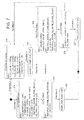
- controller 50 enters one of the three sub-states: No Error sub-state 200; Sensor Error sub-state 300; or Defrost Preparation sub-state 400, and moves between these sub-states based upon the criteria of Transitions 3-8 as described further below and shown in Fig. 3 .
- controller 50 moves from the No Error sub-state 200 to the Sensor Error sub-state 300 if an error is found to exist in either refrigerator compartment temperature sensor 22 or freezer compartment temperature sensor 32.
- any reference to “C1” refers to variables or constants associated with freezer compartment 30 and any reference to “C2” refers to variables or constants associated with refrigerator compartment 20. It will be appreciated however that “C1” and “C2” may instead refer to any two compartments of a refrigerator.
- the references to the freezer and refrigerator compartments are made to assist in the understanding of this example relative to the most common commercial units that include a refrigerator compartment and a freezer compartment. Further, this example may be implemented in side-by-side, top mount, and bottom mount refrigerators.
- Controller 50 transitions from the No Error sub-state 200 to the Defrost Preparation sub-state 400 when the criterion of the following Transition 5 is met:
- Controller 50 transitions from the Defrost Preparation sub-state 400 to the No Error sub-state 200 when the criteria of the following Transition 6 are met:
- Controller 50 transitions from the Sensor Error sub-state 300 to the Defrost Preparation sub-state 400 when the criterion of the following Transition 7 is met:
- Controller 50 transitions from the Defrost Preparation sub-state 400 to the Sensor Error sub-state 300 when the criteria of the following Transition 6 are met:
- controller 50 determines a current refrigerator mode in Figs. 4 and 5 and performs the functions of Figs. 6-10 depending on the current refrigerator mode. While in the Sensor Error sub-state 300, controller 50 performs the functions of Figs. 11-13 . While in the Defrost Preparation sub-state 400, controller 50 performs the functions of Fig. 14 .
- controller 50 determines which cooling priority to assign to the C1 compartment (e.g., freezer compartment 30) and the C2 compartment (e.g., refrigerator compartment 20) based on actual compartment temperatures (as sensed by sensors 22 and 32, set points, hysteresis and temperature constants associated with each compartment and determines a current refrigerator mode so as to decide which compartment(s) will be cooled and in what order.
- the priority calculus is executed every 1 minute and uses as reference the difference (Delta Temperature) between the actual temperature of the compartment (C#_ACTUAL-TEMP) and the control point (C#_TEMP) associated with the compartment (C#).
- the designation C# refers to a generic compartment that may be either of the C1 or C2 compartments.
- C#_HYSTERESIS Based on Delta Temperature, hysteresis (C#_HYSTERESIS) and the priority calculation parameters (C#_TEMP_HIGH_PRIORITY_CONSTANT and
- controller 50 assigns a priority for each compartment (C#) as set forth in Table 1 below.
- the freezer hysteresis, refrigerator hysteresis, the freezer and refrigerator compartment high priority constant and medium priority constant are selected based on the market preference, freezer and refrigerator storage volume and product heat gain volume for the best performance and energy consumption. These parameters may all be stored in memory of the user interface so as to be introduced to the refrigerator as a parameter set suitable for the refrigerator characteristics and the particular market and to which the particular model is to be shipped. Such markets may vary considerably, particularly depending upon the country in which the model will be sold.
- the freezer and refrigerator compartment medium priority constants can be different or the same.
- the refrigerator compartment is given a high priority at a much lower delta temperature than is the freezer compartment, which as explained further below, tends to more often give cooling priority to the refrigerator compartment over the freezer compartment.
- the current refrigerator system mode is selected from at least the following modes: a satisfied mode 204 in which neither refrigerator compartment 20 nor freezer compartment 30 is cooled, a pull-down mode 210 during which both freezer compartment 30 and refrigerator compartment 20 are alternatingly and periodically cooled, a freezer compartment (C1) cooling mode in which freezer compartment 30 is cooled, and a refrigerator compartment (C2) cooling mode in which refrigerator compartment 20 is cooled.
- a satisfied mode 204 in which neither refrigerator compartment 20 nor freezer compartment 30 is cooled
- a pull-down mode 210 during which both freezer compartment 30 and refrigerator compartment 20 are alternatingly and periodically cooled
- a freezer compartment (C1) cooling mode in which freezer compartment 30 is cooled
- a refrigerator compartment (C2) cooling mode in which refrigerator compartment 20 is cooled.
- controller 50 Whenever the refrigerator is plugged in or after a power outage, controller 50 initializes valve 45 (block 202, Fig. 4 ) and determines which refrigerator mode to select as the current mode based upon which one of Transitions 9-12 below are true.
- Controller 50 initially selects the pull-down mode 210 if Transition 9 is true, the C1 cooling mode 230 if Transition 10 is true, the C2 cooling mode 230 if Transition 11 is true, and the satisfied mode if Transition 12 is true. Only one of Transitions 9-12 may be true.
- controller 50 may change the modes from one to another based upon various criteria set forth in Transitions 13-25 as shown in Fig. 5 .
- controller 50 will generally select the satisfied mode 204 when the cooling priorities for both compartments are satisfied from the initial state 202 or if previously in the pull-down mode 210. Once in the satisfied mode 204, controller 50 will stay in the satisfied mode for at least a set time period corresponding to the parameter (SATISFIED_TIME). If at the end of this time period, the cooling priorities remain in the satisfied priority level, controller remains in the satisfied mode 204 until such time that one of the cooling priorities changes.
- SATISFIED_TIME the parameter
- controller 50 will generally select the pull-down mode 210 whenever the cooling priorities for both compartments are high and will remain in the pull-down mode until one or both of the cooling priorities is no longer high. In this event, controller 50 will transition from the pull-down mode 210 to C1 cooling mode 230 if the cooling priority of the freezer (C1_PRIORITY) is equal to or greater than that of the refrigerator (C2_PRIORITY), otherwise it will transition from the pull-down mode 210 to C2 cooling mode 270 if the cooling priority of the freezer (C1_PRIORITY) is less than that of the refrigerator (C2_PRIORITY).
- C1_PRIORITY the cooling priority of the freezer
- C2_PRIORITY the cooling priority of the freezer
- controller 50 determines the cooling priorities of the refrigerator and freezer compartments 20 and 30, and how controller determines a current refrigerator mode from the satisfied mode 204, the pull-down mode 210, the freezer (C1) cooling mode 230, and the refrigerator (C2) cooling mode 270, the controller functions performed in each of these modes is now described with reference to Figs. 6-10 .
- Fig. 6 shows the functions 205 of controller 50 during the satisfied mode 204 in which cooling is no longer required.
- controller 50 turns of compressor 40, controls valve 45 to be closed to freezer evaporator 34 and open to refrigerator evaporator 24, expires the extended refrigerator fan 26 run time to turn that fan off, restarts a timer for which valve 45 is open to refrigerator evaporator 24, and sets the pump out flag to ON.
- Fig. 7 shows the functions 212-226 that controller 50 may perform during the pull-down mode 210 in which pull-down cooling is required (both compartments warm). As illustrated, controller 50 executes some or all of the functions 212-226 in a particular sequence depending upon which of the following Conditions 1-8 are true:
- controller 50 turns on compressor 40, controls valve 45 by opening it to the refrigerator (C2) compartment, and after a specified delay period, turns refrigerator fan 26 on at a 100% duty cycle in order to prepare the loads to cool the refrigerator (C2) compartment.
- Pre-C2 Pull Down function 214 is also executed following Pull Down Pump Out function 212 and function 216 in which the C2_PUMP_OUT_TIME timer is restarted following a PROTECTION_OFF_TIME timeout after function 212 is executed.
- C2 Pull Down function 218 is the actual cooling of the refrigerator (C2) compartment. After PULL_DOWN_COMP_TIME it will wait for a refrigerator fan extend period before turning off refrigerator fan 26, if the product needs to switch to cool the freezer compartment or go to the satisfied mode, depending on the priorities for each compartment. More specifically, if either compartment priority is no longer at the high priority level, function 220 is performed whereby the PUMP_OUT_FLAG is set to OFF before moving to a different mode and its associated functions. If the priorities of both compartments are still high (Condition 6), controller 50 executes the Pre-C1 Pull Down function 222 whereby the loads are prepared to cool the freezer (C1) compartment.
- controller 50 When executing the Pre-C1 Pull Down function 222, controller 50 turns on freezer fan 36, closes valve 45 to the refrigerator compartment and opens it to the freezer compartment while keeping compressor 40 on. Thereafter, controller 50 executes the C1 Pull Down function 224 which is the actual cooling of the freezer (C1) compartment. After PULL_DOWN_COMP_TIME it will switch to another state, depending on the priorities for each compartment. More specifically, if either compartment priority is no longer at the high priority level, function 226 is performed whereby the PUMP_OUT_FLAG is set to ON before moving to a different mode and its associated functions. If the priorities of both compartments are still high (Condition 8), controller 50 returns to the Pull Down Pump Out function 212.
- freezer fan 36 C1_Fan
- refrigerator fan 26 C2_Fan
- Figs. 8 and 9 show the functions 232-258 performed by controller 50 during the C1 cooling mode 230 in which freezer compartment 30 is cooled continuously until such time as one of Transitions 16, 20, or 23 (see Fig. 5 ) causes controller 50 to go to another refrigerator mode (i.e., 204, 210, or 270).
- cooling of freezer compartment 30 includes three main functions including C1 Pre-Cooling function 232 in which loads are prepared to cool the freezer (C1) compartment, a C1Cooling function 256 that follows C1 Pre-Cooling function 232, and a C1 Extra Cooling function 258 that may be executed after C1Cooling function 256.
- Fig. 9 shows the various sub-functions 234-254 performed in Pre-Cooling function 232.
- controller 50 first decides in block 234 whether compressor 40 is ON or OFF. Note that compressor 40 may be ON or OFF depending upon which refrigerator mode the controller was in, prior to entering the C1 Cooling mode 204. If compressor 40 is OFF, controller 50 executes sub-function 236. Otherwise, controller 50 executes function 238 in which it decides whether valve 45 is open or closed to refrigerator evaporator 24. If it is closed to refrigerator evaporator 24, controller 50 opens valve 45 to freezer evaporator 34 in block 240 and then executes sub-function block 242 in which a timer is restarted to monitor the time valve 45 is open in this manner.
- controller 50 sets another timer (C1_ON_COOLING_TIMER) to be equal to C1_COOLING_TIME. If controller 50 determines in block 238 that valve 45 is open to refrigerator evaporator 24, controller 50 executes block 246 whereby valve 45 is opened to freezer evaporator 34 and then after a delay, valve 45 is closed to refrigerator evaporator 24 while remaining open to freezer evaporator 34. Then, after a short delay, freezer fan 36 is turned on in block 248 before proceeding to the aforementioned block 242.
- C1_ON_COOLING_TIMER another timer
- controller 50 determines that compressor 40 is OFF, it determines in block 236 whether valve 45 is open to both evaporators 24 and 34 or only one of the evaporators. If valve 45 is open to both evaporators, controller 50 executes block 250 whereby valve 45 is closed to refrigerator evaporator 24 and compressor 40 is turned on. Then, after a longer delay, freezer fan 36 is turned on in block 252 before proceeding to the aforementioned block 242. If valve 45 is open to only one of the evaporators, controller 50 executes block 254 whereby valve 45 is closed to refrigerator evaporator 24 and opened to freezer evaporator 34 and compressor 40 is turned on. Then, controller 50 executes the aforementioned blocks 248 and 242.
- controller 50 executes the C1 Cooling function 256 in which the freezer (C1) compartment continues to get colder until one of Transitions 16, 20, or 23 force controller 50 to leave the C1 cooling mode 230 based on the priority of the compartments. If none of Transitions 16, 20, or 23 has forced controller 50 to leave the C1 cooling mode 230, the C1 Extra Cooling function 258 adds an extra cooling time to the C1_ON_COOLING_TIMER to allow the temperature in the freezer (C1) compartment to continue to decrease.
- controller 50 If one of Transitions 16, 20, or 23 force controller 50 to leave the C1 cooling mode 230, controller first closes valve 45 to freezer evaporator 34, waits for a fan delay period and turns off freezer fan 36 (C1_FAN), and then sets PUMP_OUT_FLAG to ON in block 256.
- controller 50 When controller 50 goes from C1 cooling mode 230 to another mode the freezer (C1) fan 36 will remain ON until C1_COOLING_C1_FAN_EXTEND is expired. In order to avoid the system to switch to another cooling mode at beginning of C1 cooling mode 230, controller 50 shall stay in C1 cooling Mode for a minimum amount of time (C1_ON_COOLING TIME), even if the C2_PRIORITY is higher than C1_PRIORITY.
- Fig. 10 shows the functions 272-280 executed by controller 50 when in the C2 cooling mode 270 in which the refrigerator (C2) compartment 20 is cooled continuously until such time as one of Transitions 18, 22, or 24 (see Fig. 5 ) causes controller 50 to go to another refrigerator mode (i.e., 204, 210, or 230).
- the system shall stay in C2 Cooling Mode for a minimum amount of time (C2_ON_COOLING TIME), even iftransitioning conditions are met.
- the process begins with a determination as to whether the PUMP_OUT_FLAG is ON or OFF. If it is ON, controller 50 proceeds to the C2 Pump Out function 272, and if it is OFF, controller 50 proceeds to the C2 Pre-Cooling function 274.
- controller 50 closes valve 45 to both evaporators and turns on compressor 40 to allow refrigerant gas return to the condenser.
- controller 50 will wait for the compressor protection time out before it restarts C2_PUMP_OUT_TIME in block 276 and proceeds to C2 Pre-Cooling function 274 when C2_PUMP_OUT_TIME is greater than C2_REFRIGERANT_RETURN_TIME.
- the loads are prepared to cool the refrigerator (C2) compartment. Specifically, the compressor is turned on, valve 45 is opened to refrigerator evaporator 34, turns refrigerator fan 26 on at 100% duty cycle after a delay, and sets C2_ON_COOLING_TIMER to C2_COOLING_TIME.
- C2 Cooling function 278 is executed after C2 Pre-Cooling function 274.
- C2 Cooling function 278 the temperature in refrigerator compartment 20 gets colder until one of Transitions 18, 22, or 24 force controller 50 to leave the C2 cooling mode 270 based on the priority status of both compartments. If transitioning conditions are not met, controller 50 will add an extra cooling time to C2_ON_COOLING_TIMER to allow the temperature in refrigerator compartment 20 to continue to drop in the C2 Extra Cooling function 280.
- refrigerator fan 26 (C2 fan) will remain on until C2_COOLING_C2_FAN_EXTEND is expired or C2_ACTUAL_TEMP - C2 EVAP ACTUAL TEMP ⁇ C2_FAN_OFF_DELTA_T as shown in block 278.
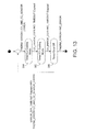
- Figs. 11-13 show state diagrams for when the refrigerator is in the Sensor Error sub-state 300, which is active while a sensor error is detected on the sensor associated with one or both compartments (per Fig. 3 ). Sub-states are described below. When the system comes out of error it shall calculate the priorities and based on this go to the appropriate cooling mode.
- controller 50 determines whether the sensor error is in the FC (C1) temperature sensor 32, the RC (C2) temperature sensor 22, or both, and operates in the sub-states shown in Fig. 11 when the sensor error is in the FC (C1) temperature sensor 32, in the sub-states shown in Fig. 12 when the sensor error is in the RC (C2) temperature sensor 22, and in the sub-states shown in Fig. 13 when the sensor error is in the both the FC (C1) temperature sensor 32 and the RC (C2) temperature sensor 22.
- Timed C1 Cooling Mode 302 operates the same as C1 Cooling Mode 230 except that, as the C1 sensor cannot be read due to its error, no logic related to C1_PRIORITY is executed. As a consequence, the product remains in Timed C1 Cooling Mode 302 for a determined period of time (C1_ERROR_COOLING_TIMEOUT). Thus, the exit condition for Timed C1 Cooling Mode 302 will be only C1_ERROR_COOLING_TIMEOUT expired. Once it comes out of Timed C1 Cooling Mode 302, controller 50 shall stay in Satisfied Mode 204 until C2_PRIORITY > 0, at which time it will repeat the cycle shown in Fig. 11 until such time that a sensor error is no longer detected.
- Timed C2 Cooling Mode 304 is the same as described above.
- Timed C2 Cooling Mode 304 operates the same as C2 Cooling Mode 270 except that, as the C2 sensor cannot be read due to its error, no logic related to C2_PRIORITY is executed. As a consequence, the product remains in Timed C2 Cooling Mode 304 for a determined period of time (C2_ERROR_COOLING_TIMEOUT).
- C2_ERROR_COOLING_TIMEOUT shall be greater than C2_REFRIGERANT_RETURN_TIME to allow C2 Pump Out be executed before cooling C2.Once it comes out of C1 Cooling Mode 230, controller 50 shall stay in Satisfied Mode 204 until C1_PRIORITY > 0, at which time it will repeat the cycle shown in Fig. 12 until such time that a sensor error is no longer detected. As the C2 sensor is in error, controller 50 shall execute C2 fan extension for C2_COOLING_C2_FAN_EXTEND, after exit Timed C2 Cooling Mode 304.
- controller 50 will run Timed C2 Cooling Mode 304 followed by Timed C1 Cooling Mode 302 and then a Timed Error Off mode 306 for ERROR_OFF_TIMEOUT .
- Timed Error Off mode 306 the refrigerator remains in Satisfied Mode 204 for a determined period of time (ERROR_OFF_TIMEOUT).
- controller 50 shall execute C2 fan extension for C2_COOLING_C2_FAN_EXTEND, after exit Timed C2 Cooling Mode. As soon as controller 50 enters this routine it shall set PUMP OUT FLAG ON.
- refrigerator evaporator temperature sensor 28 (C2 Evap Sensor) is used to control refrigerator fan 26 (C2 Evap fan) extension. If refrigerator evaporator temperature sensor 28 (C2 Evap Sensor) is in error, control refrigerator fan 26 (C2 Evap fan) extension will be executed until C2_COOLING_C2_FAN_EXTEND is elapsed.
- Fig. 14 shows the details of the Defrost Preparation sub-state 400 ( Fig. 3 ).
- controller 50 will execute C2 Cooling Mode 270 until the refrigerator C2 compartment temperature is satisfied or until C2_VALVE_OPEN_TIMER is greater than C2_ON_COOLING_TIMER.
- C2_ACTUAL_TEMP the refrigerator compartment temperature
- C2_VALVE_OPEN_TIMER the freezer compartment
- C2_ON_COOLING_TIMER For the freezer (C1) compartment there is no temperature restriction to execute a defrost. It can occur at any time. No Extra Cooling Time is allowed on C2 Cooling during defrost preparation.
- valve 45 shall be initialized.
- controller 50 opens valve 45 to freezer evaporator 34, turns freezer fan 36 off, opens valve 45 to refrigerator evaporator 24, turns refrigerator fan 26 off, and turns compressor 40 off.
- Fig. 15 shows Temperature Controller Disabled State 102, which describes the operation of both compartments of the refrigerator while temperature control is disabled.
- controller 50 performs an idle function 103 in which it turns off compressor 40, closes valve 45 to freezer evaporator 34, turns freezer fan 36 off, closes valve 45 to refrigerator evaporator 24, and turns refrigerator fan 26 off.
- Fig. 16 is a chart showing the power consumption (in wattage) of the refrigerator over time along with the respective average temperatures of the freezer and refrigerator compartments. As apparent from this chart, power consumption is initially very high which is when the temperatures of the refrigerator and freezer compartments would be high. After a defrost cycle. The product could be set to pull down mode, freezer cooling mode or refrigerator cooling mode, depending on the freezer and refrigerator cooling priorities. In Fig. 16 , controller 50 set the refrigerator to the refrigerator cooling mode for a short time, then switched to freezer cooling mode when the freezer cooling priority changed into the high level and the refrigerator cooling priority was not at the high level. After the freezer temperature was reduced enough to lower the freezer cooling priority, controller 50 switched the refrigerator to the refrigerator cooling mode followed by another freezer cooling cycle before the refrigerator entered into the satisfied mode.
- the power consumption is more cyclical and tends to spike when the compressor is first turned on but then tapers off as the refrigerator compartment (C2) cooling mode begins.
- the compressor remains on while the system transitions to the freezer compartment (C1) cooling mode and then turns off until the next refrigerator compartment (C2) cooling mode is to begin.
- the compressor is not turned on and off as frequently, instead it is turned on longer during each on/off cycle and is off longer during each cycle. By turning the compressor on and off less frequently, there are far fewer of the power consumption spikes over time and therefore lower overall power consumption.
- Tables 3 and 4 below are provided to give some exemplary values of the various parameters and variables used in the above example. These parameters and variables are not limited to the values provided and may be varied to achieve optimal performance, and more specifically to minimize power consumption.
- Table 3 Parameters Name Default Value (in units) Range (in units) Resolution (1 bit) Units Comment C1_TEMP -18 -2048 .. 2048 1/16 °C Compartment temperature control point C1_HYSTERESIS 2,22 -2048 .. 2048 1/16 °C Compartment Hysteresis C1_TEMP_HIGH_PRIORITY_CONSTANT 5,55 0 ..
- PULL_DOWN_C1_FAN_EXTEND 2 0 .. 255 1 min Amount of time to keep the C1 fan on after the end of C1 cooling during Pull Down mode.
- PULL_DOWN_C2_FAN_DELAY 0 0 .. 255 1 min Amount of time to keep the C2 fan off before start of C2 cooling during Pull Down mode.
- PULL_DOWN_C2_FAN_EXTEND 20 0 .. 255 1 min Amount of time to keep the C2 fan on after the end of C2 cooling during Pull Down mode.
- PULL_DOWN_C2_VALVE_CLOSE_DELAY 60 0 .. 1275 5 sec Amount of time to keep C2 valve open before starting C1 cooling during Pull Down mode.
- PULL_DOWN_COMP_TIME 20 0 .. 255 1 min Amount of time that C1 or C2 valve has to remain opened during each cycle of the Pull Down Mode.
- C1_COOLING_TIME 15 0 .. 255 1 min Minimum time that the product must remain in C Cooling Mode if C1 compartment is not satisfied.
- C1_COOLING_C1_FAN_EXTEND 2 0 .. 255 1 min Amount of time to keep the C1 fan on after the end of C1 cooling mode.
- C1_COOLING_C1_LONG_FAN_DELAY 5 0 .. 255 1 min Amount of maximum time to keep the C fan off after the 1st C1 cooling cycle after C1 defrost cycle.
- C1_COOLING_C1_SHORT_FAN_DELAY 20 0 .. 1275 5 sec Amount of maximum time to keep the C fan off after the start of C1 cooling mode and not right after C defrost C1_COOLING_C2_VALVE_EXTEND 0 0..255 1 min Amount of time to keep the C2 valve opened before being closed when product switches from C2 cooling to C1 cooling directly.
- C2_COOLING_TIME 15 0..255 1 min Minimum time that the product must remain in C2 Cooling Mode if C2 sensor is not satisfied.
- C2_COOLING_C2_FAN_EXTEND 20 0..255 1 min Maximum amount of time to keep the C2 fan on after the end of C2 cooling mode.
- C2_REFRIGERANT_RETURN_TIME 1 0..255 1 min Amount of necessary time to the refrigerant fluid to return to condenser area.
- C2_ERROR_COOLING_TIMEOUT 8 0..255 1 min Amount of time to stay in C2 cooling mode during C2 sensor error.
- SATISFIED_TIME 7 0..255 1 min Amount of time that the product must remain in Satisfied Mode before leave such state.
- EXTRA_COOLING_TIME 5 0..255 1 min Extra amount of time to stay in C1 or C2 Cooling mode.
- DEFROST_DELAY_TIME 3 0..255 1 min This timer is used to count the time a Temperature Control instance will not be active after a Defrost.
- ERROR_OFF_TIMEOUT 20 0..255 1 min Amount of time to stay in satisfied mode during C1 and C2 sensor error.
- Table 4 Variable Name Default Value Range Resolution Units Comment C1_ACTUAL_TEMP -2048 .. 2048 1/16 °C The compartment 1 sensor actual temperature reading.
- C2_ACTUAL_TEMP -2048 .. 2048 1/16 °C The compartment2 sensor actual temperature reading.
- C2_EVAP_ACTUAL_TEMP -2048 .. 2048 1/16 °C The compartment2 Evap sensor actual temperature reading.
- C1_VALVE_OPEN_TIMER 0 0..2048 1 min Defines time that C1 valve is open.
- C1_VALVE_CLOSE_TIMER 0 0..2048 1 min Defines time that C valve is close.
- C1_ON_COOLING_TIMER 0 0..2048 1 min Defines the time since the products start C1 cooling.
- C2_VALVE_OPEN_TIMER 0 0..2048 1 min Defines time that C2 valve is open.
- C2_VALVE_ CLOSE_TIMER 0 0..2048 1 min Defines time that C2 valve is close.
- C2_ON_COOLING_TIMER 0 0..2048 1 min Defines the time since the products start C2cooling.
- C2_PUMP_OUT_TIME 0 0..2048 1 Min Defines the time since C1 and C2 valves are closed and compressor is ON.
- TEMP_CONTROL_ENABLE DISABLED ENABLED N/A N/A Defines if the temperature controller is enabled, disabled or locked.
Landscapes
- Engineering & Computer Science (AREA)
- Physics & Mathematics (AREA)
- Mechanical Engineering (AREA)
- Thermal Sciences (AREA)
- General Engineering & Computer Science (AREA)
- Chemical & Material Sciences (AREA)
- Combustion & Propulsion (AREA)
- Devices That Are Associated With Refrigeration Equipment (AREA)
Abstract
A refrigerator and method are provided where the refrigerator includes at least a refrigerator compartment (C2) cooled by a refrigerator evaporator, a freezer compartment (C1) cooled by a freezer evaporator, a compressor, a controller, and a valve that selectively couples the compressor to a selected one of the refrigerator evaporator and the freezer evaporator. The method includes determining both refrigerator and freezer compartment cooling priorities as a function of the respective actual refrigerator or freezer compartment temperatures, desired refrigerator or freezer compartment temperatures, and refrigerator or freezer hysteresis. The refrigerator and freezer compartment cooling priorities having one of the following priority levels: high, medium, low, and satisfied. The method further includes selecting a current refrigerator system mode in response to the refrigerator and freezer compartment cooling priorities.
Description
- The present invention generally relates to a sequential dual evaporator refrigerator, and more particularly relates to a particular method of controlling the same.
- According to one aspect of the present invention, a method is disclosed for controlling a refrigerator having at least a refrigerator compartment cooled by a refrigerator evaporator, a freezer compartment cooled by a freezer evaporator, a compressor, and a valve that selectively couples the compressor to a selected one of the refrigerator evaporator and the freezer evaporator. The method comprises the steps of: (a) determining the refrigerator compartment cooling priority as a function of the actual refrigerator compartment temperature, a desired refrigerator compartment temperature, and a refrigerator hysteresis, wherein the refrigerator compartment cooling priority has one of the following priority levels: high, medium, low, and satisfied; (b) determining the freezer compartment cooling priority as a function of the actual freezer compartment temperature, a desired freezer compartment temperature, and a freezer hysteresis, wherein the freezer compartment cooling priority has one of the following priority levels: high, medium, low, and satisfied; (c) selecting a current refrigerator system mode in response to a refrigerator compartment cooling priority and a freezer compartment cooling priority, the current refrigerator system mode is selected from at least the following modes: a pull down mode during which both the freezer and refrigerator compartments are alternatingly and periodically cooled, a refrigerator compartment cooling mode in which the refrigerator compartment is cooled, a freezer compartment cooling mode in which the freezer compartment is cooled, and a satisfied mode in which neither the refrigerator or freezer compartments are cooled; and (d) controlling the valve and the compressor to selectively cool one, both or neither of the refrigerator compartment and the freezer compartment based on the current refrigerator system mode.
- According to another aspect of the present invention, a refrigerator is provided that comprises: a refrigerator compartment; a freezer compartment; a refrigerator compartment temperature sensor for sensing an actual refrigerator compartment temperature; a freezer compartment temperature sensor for sensing an actual freezer compartment temperature; a refrigerator evaporator associated with the refrigerator compartment; a freezer evaporator associated with the freezer compartment; a compressor; a valve fluidly coupled between the compressor and the refrigerator evaporator and the freezer evaporator, wherein, in response to a valve control signal, the valve is selectively operative to open or close between the compressor and the refrigerator evaporator to allow or prevent refrigerant from flowing therebetween and to open or close between the compressor and the freezer evaporator to allow or prevent refrigerant from flowing therebetween; and a controller electrically coupled to the compressor, the valve, the refrigerator compartment temperature sensor, and the freezer compartment temperature sensor. The controller is provided for turning the compressor on and off, for selecting operational states of the valve, and for determining a current refrigerator system mode in response to a refrigerator compartment cooling priority and a freezer compartment cooling priority, the current refrigerator system mode is selected from at least the following modes: a pull down mode during which both the freezer and refrigerator compartments are alternatingly and periodically cooled, a refrigerator compartment cooling mode in which the refrigerator compartment is cooled, a freezer compartment cooling mode in which the freezer compartment is cooled, and a satisfied mode in which neither the refrigerator or freezer compartments are cooled. The refrigerator compartment cooling priority has one of the following priority levels: high, medium, low, and satisfied, wherein the refrigerator compartment cooling priority is determined of as a function of the actual refrigerator compartment temperature, a desired refrigerator compartment temperature, and a refrigerator hysteresis. The freezer compartment cooling priority has one of the following priority levels: high, medium, low, and satisfied, wherein the freezer compartment cooling priority is determined of as a function of the actual freezer compartment temperature, a desired freezer compartment temperature, and a freezer hysteresis.
- The invention will be further described by way of example with reference to the accompanying drawings, in which:
-
Fig. 1 is a schematic representation of a refrigerator constructed in accordance with an embodiment of the present invention; -
Fig. 2 is a temperature controller main state diagram; -
Fig. 3 is a temperature controller enable state diagram; -
Fig. 4 is a control initialization state machine; -
Fig. 5 is a no error state machine; -
Fig. 6 is a satisfied mode state diagram; -
Fig. 7 is a pull-down mode state diagram; -
Fig. 8 is a C1 cooling mode state diagram; -
Fig. 9 is a process C1 pre-cooling activity diagram; -
Fig. 10 is a C2 cooling mode state diagram; -
Fig. 11 is a C1 sensor error state diagram; -
Fig. 12 is a C2 sensor error state diagram; -
Fig. 13 is a C1 and C2 sensor error state diagram; -
Fig. 14 is a defrost preparation state diagram; -
Fig. 15 is a temperature controller disabled state diagram; and -
Fig. 16 is a graph illustrating average refrigerator compartment temperature, average freezer compartment temperature and wattage taken with respect to time for a refrigerator constructed in accordance with the present invention. - Reference will now be made in detail to the present preferred embodiment of the invention, an example of which is illustrated in the accompanying drawings. Wherever possible, the same reference numerals will be used throughout the drawings to refer to the same or like parts.
-
Fig. 1 shows a schematic representation of arefrigerator 10 according to a first embodiment. The refrigerator shown is a sequential dual evaporator refrigerator in that it includes arefrigerator compartment 20 and afreezer compartment 30 as well as separate evaporators for each compartment, namely, arefrigerator evaporator 24 associated withrefrigerator compartment 20 and afreezer evaporator 34 associated withfreezer compartment 30, wherein the refrigerant is sequentially supplied to each evaporator using avalve 45 and acompressor 40. Valve 45 is fluidly coupled betweencompressor 40 andrefrigerator evaporator 24 andfreezer evaporator 34, wherein, in response to a valve control signal,valve 45 is selectively operative to open or close betweencompressor 40 andrefrigerator evaporator 24 to allow or prevent refrigerant from flowing therebetween and to open or close betweencompressor 40 andfreezer evaporator 34 to allow or prevent refrigerant from flowing therebetween. -
Refrigerator 10 may further comprise a refrigerator compartment (RC)temperature sensor 22 for sensing an actual refrigerator compartment temperature; a freezer compartment (FC)temperature sensor 32 for sensing an actual freezer compartment temperature; and acontroller 50 electrically coupled tocompressor 40,valve 45, refrigeratorcompartment temperature sensor 22, and freezercompartment temperature sensor 32.Controller 50 is programmed or otherwise configured for turningcompressor 40 on and off, for selecting operational states ofvalve 45, and for determining a current refrigerator system mode in response to a refrigerator compartment cooling priority and a freezer compartment cooling priority. -
Refrigerator 10 may further comprise arefrigerator fan 26 coupled to controller 50 for moving airpast refrigerator evaporator 24 intorefrigerator compartment 20, wherecontroller 50 turnsrefrigerator fan 26 on and off. As described further below, the refrigerator fan on time is extended at the end of each refrigerator cooling cycle, and is turned off when the actual refrigerator evaporator temperature is getting closer to the actual refrigerator compartment temperature. The refrigerator fan extension helps to continue cooling the refrigerator compartment and also helps to defrost the refrigerator evaporator without a heater.Refrigerator 10 may also further comprise afreezer fan 36 coupled tocontroller 50 for moving airpast freezer evaporator 34 intofreezer compartment 30, wherecontroller 50 turnsfreezer fan 36 on and off. - A refrigerator
evaporator temperature sensor 28 may be provided on or atrefrigerator evaporator 24 so as to sense the temperature thereof and provide the sensed temperature to controller 50. Similarly, a freezerevaporator temperature sensor 38 may be provided on or atfreezer evaporator 34 so as to sense the temperature thereof and provide the sensed temperature to controller 50.Controller 50 may use these temperature readings to controlfans -
Refrigerator 10 may additionally include acondenser 42 and adrier 44 fluidly connected betweencompressor 40 andvalve 45. Acheck valve 48 may be provided between the output line offreezer evaporator 34 andcompressor 40 so as to prevent backflow of refrigerant tofreezer evaporator 34. - Lastly,
refrigerator 10 may include auser interface 55 coupled tocontroller 50 for allowing a user to manually set a desired refrigerator compartment temperature, and a desired freezer compartment temperature.User interface 55 may optionally include door open sensors for bothrefrigerator compartment 20 andfreezer compartment 30. - Valve 45 is preferably a three-way valve, but may consist of two or more two-way valves. Valve 45 is fluidly coupled to
refrigerator evaporator 24 via a firstcapillary tube 47 and is coupled tofreezer evaporator 34 through a secondcapillary tube 49. Valve 45 may have four different positions: (1) open torefrigerator evaporator 24 only (whencontroller 50 determines that the variables C2_VALVE = OPEN and C1_VALVE = CLOSE); (2) open tofreezer evaporator 34 only (whencontroller 50 determines that the variables C1_VALVE = OPEN and C2_VALVE = CLOSE); (3) open to bothrefrigerator evaporator 24 and freezer evaporator 34 (whencontroller 50 determines that the variables C1_VALVE = OPEN and C2_VALVE = OPEN); and (4) closed to bothrefrigerator evaporator 24 and freezer evaporator 34 (whencontroller 50 determines that the variables C1_VALVE = CLOSE and C2_VALVE = CLOSE). - Having generally described the structure of
refrigerator 10, a method for controllingrefrigerator 10 is now described. The method is generally executed bycontroller 50, which executes an algorithm in order to control the operation ofvalve 45,compressor 40,refrigerator fan 26, andfreezer fan 36 in response to various inputs fromuser interface 55,RC temperature sensor 22,FC temperature sensor 32, refrigeratorevaporator temperature sensor 28, and freezerevaporator temperature sensor 38. The method generally may comprise the steps of: (a) determining the refrigerator compartment cooling priority as a function of the actual refrigerator compartment temperature, a desired refrigerator compartment temperature, and a refrigerator hysteresis, wherein the refrigerator compartment cooling priority has one of the following priority levels: high, medium, low, and satisfied; (b) determining the freezer compartment cooling priority as a function of the actual freezer compartment temperature, a desired freezer compartment temperature, and a freezer hysteresis, wherein the freezer compartment cooling priority has one of the following priority levels: high, medium, low, and satisfied; (c) selecting a current refrigerator system mode in response to a refrigerator compartment cooling priority and a freezer compartment cooling priority, the current refrigerator system mode is selected from at least the following modes: a pull-down mode during which both the freezer and refrigerator compartments are alternatingly and periodically cooled, a refrigerator compartment cooling mode in which the refrigerator compartment is cooled, a freezer compartment cooling mode in which the freezer compartment is cooled, and a satisfied mode in which neither the refrigerator nor freezer compartments is cooled; and (d) controlling the valve and the compressor to selectively cool one, both or neither of the refrigerator compartment and the freezer compartment based on the current refrigerator system mode. The freezer hysteresis may be different from the refrigerator hysteresis, and is preferably greater than the refrigerator hysteresis. However, this is not a necessary condition. - The refrigerator system mode may be set to satisfied mode when both the refrigerator compartment cooling priority and the freezer compartment cooling priority are in the satisfied priority levels. The refrigerator system mode may be set to pull-down mode when both the refrigerator compartment cooling priority and the freezer compartment cooling priority are in the high priority levels.
- In general, and with some exceptions explained below, the refrigerator system mode is set to refrigerator compartment cooling mode when the refrigerator compartment cooling priority is greater than the freezer compartment cooling priority. In general, and with some exceptions explained below, the refrigerator system mode may be set to freezer compartment cooling mode when the freezer compartment cooling priority is at the high priority level and the refrigerator compartment cooling priority is not at the high priority level, or when the actual refrigerator compartment temperature is lower than the desired refrigerator compartment temperature minus the refrigerator hysteresis.The refrigerator compartment cooling priority may be determined to be in a satisfied priority level when the actual refrigerator compartment temperature minus the desired refrigerator compartment temperature is less than or equal to the refrigerator hysteresis. The freezer compartment cooling priority may be determined to be in a satisfied priority level when the actual freezer compartment temperature minus the desired freezer compartment temperature is less than or equal to the freezer hysteresis.
-
Controller 50 may determine that the refrigerator compartment cooling priority should be in a high priority level when the actual refrigerator compartment temperature minus the desired refrigerator compartment temperature is greater than or equal to a sum of a refrigerator compartment high priority constant and the refrigerator hysteresis. The freezer compartment cooling priority may be determined to be in a high priority level when the actual freezer compartment temperature minus the freezer refrigerator compartment temperature is greater than or equal to a sum of a freezer compartment high priority constant and the freezer hysteresis. The freezer compartment high priority constant may be the same as or different from the refrigerator compartment high priority constant. -
Controller 50 may determine that the refrigerator compartment cooling priority should be in a medium priority level when the actual refrigerator compartment temperature minus the desired refrigerator compartment temperature is: (1) greater than a sum of a refrigerator compartment medium priority constant and the refrigerator hysteresis, and (2) less than or equal to a sum of a refrigerator compartment high priority constant and the refrigerator hysteresis. The freezer compartment cooling priority may be determined to be in a medium priority level when the actual freezer compartment temperature minus the freezer refrigerator compartment temperature is: (1) greater than a sum of a freezer compartment medium priority constant and the freezer hysteresis, and (2) less than or equal to a sum of a freezer compartment high priority constant and the freezer hysteresis. The freezer and refrigerator compartment medium priority constants can be different or the same. - The refrigerator compartment cooling priority is determined to be in a low priority level when the actual refrigerator compartment temperature minus the desired refrigerator compartment temperature is: (1) greater than the refrigerator hysteresis, and (2) less than or equal to a sum of a refrigerator compartment medium priority constant and the refrigerator hysteresis. The freezer compartment cooling priority is determined to be in a low priority level when the actual freezer compartment temperature minus the freezer refrigerator compartment temperature is: (1) greater than the freezer hysteresis, and (2) less than or equal to a sum of a freezer compartment medium priority constant and the freezer hysteresis. The freezer and refrigerator compartment medium priority constants can be different or the same.
- As explained further below, the embodiment disclosed herein allows the ON/OFF cycles of
compressor 40 to be reduced which lowers power consumption. The values of the hysteresis and medium and high priority constants may be independent for the freezer and refrigerator compartments and may be optimized to minimize the ON/OFF cycles ofcompressor 40. - Having generally described the operation of
controller 50, a more specific example of operation is described below with respect toFigs. 2-16 . The following example is provided for purposes of illustration and should not be considered as limiting the scope of the present invention. - In this example, various parameters and variables are used by the algorithm executed by
controller 50. Parameters are constants that may be stored in non-volatile memory (if available) or in program memory. Parameters may be used to set values for key parts of an algorithm (especially those that are difficult to specify without performance evaluation or are model specific). These variables may be easily modified for development of algorithms and calibration of product performance. A list of the parameters and some exemplary default values, ranges, resolutions and units are provided in Table 3 appearing at the end of this example. A list of the variables and some exemplary default values, ranges, resolutions and units are provided in Table 4 appearing at the end of this example. The parameters and variables in Tables 3 and 4 are just for reference. Each application may have its own default values for parameters and variables. -
Fig. 2 shows a main temperature controller state diagram in which the high-level behavior is illustrated of the dual evaporator temperature controller operation. Sub-states are described below with respect to other drawing figures. - As shown in
Fig. 2 , there are two main states including a Temperature Controller Enabled andLocked state 100 and a Temperature ControllerDisabled state 102.Controller 50 may enter either state as a default state upon power-up, but will transition between states based upon certain transition criteria. Specifically,controller 50 transitions from the Temperature Controller Enabled andLocked state 100 to the Temperature ControllerDisabled state 102 when the following criterion ofTransition 1 is met: - Receive opcode "set Temp Control Enable (TEMP_CONTROL_ENABLE==DISABLED)"
-
Controller 50 transitions from the Temperature ControllerDisabled state 102 to the Temperature Controller Enabled andLocked state 100 when the following criterion ofTransition 2 is met: - Receive opcode "set Temp Control Enable (TEMP_CONTROL_ENABLE==ENABLED)" OR receive opcode "set Temp Control Enable (TEMP_CONTROL_ENABLE==LOCKED)"
- When in the Temperature Controller
Disabled state 102,controller 50 performs the functions described below and shown inFig. 15 and then sits idle until such time that the criterion ofTransition 2 is met. When in the Temperature Controller Enabled andLocked state 100,controller 50 enters one of the three sub-states: No Error sub-state 200; Sensor Error sub-state 300; or Defrost Preparation sub-state 400, and moves between these sub-states based upon the criteria of Transitions 3-8 as described further below and shown inFig. 3 . For example,controller 50 moves from the No Error sub-state 200 to the Sensor Error sub-state 300 if an error is found to exist in either refrigeratorcompartment temperature sensor 22 or freezercompartment temperature sensor 32. More specifically, as set forth inTransition 3 below, if the variable THERM_ERROR is found to be equal to C1_SENSOR_ERROR, which represents an error in the output from freezercompartment temperature sensor 32, or to be equal to C2_SENSOR_ERROR, which represents an error in the output from refrigeratorcompartment temperature sensor 22,controller 50 transitions to the Sensor Error sub-state 300. If the variable THERM_ERROR is later found to be equal to NO_ERROR,controller 50 transitions back to the No Error sub-state 200 perTransition 4 below. - THERM_ERROR == C1_SENSOR_ERROR OR THERM_ERROR == C2_SENSOR_ERROR
- THERM_ERROR ==NO_ERROR
- It should be noted that for purposes of this example, any reference to "C1" refers to variables or constants associated with
freezer compartment 30 and any reference to "C2" refers to variables or constants associated withrefrigerator compartment 20. It will be appreciated however that "C1" and "C2" may instead refer to any two compartments of a refrigerator. The references to the freezer and refrigerator compartments are made to assist in the understanding of this example relative to the most common commercial units that include a refrigerator compartment and a freezer compartment. Further, this example may be implemented in side-by-side, top mount, and bottom mount refrigerators. -
Controller 50 transitions from the No Error sub-state 200 to the Defrost Preparation sub-state 400 when the criterion of the followingTransition 5 is met: - DEFROST_STATE == READY TO DEFROST
-
Controller 50 transitions from the Defrost Preparation sub-state 400 to the No Error sub-state 200 when the criteria of the followingTransition 6 are met: - (DEFROST_STATE == MONITOR AND THERM_ERROR == NO_ERROR AND
- DEFROST_DELAY_TIMER timeout)
-
Controller 50 transitions from the Sensor Error sub-state 300 to the Defrost Preparation sub-state 400 when the criterion of the followingTransition 7 is met: - DEFROST_STATE == READY TO DEFROST
-
Controller 50 transitions from the Defrost Preparation sub-state 400 to the Sensor Error sub-state 300 when the criteria of the followingTransition 6 are met: - (DEFROST_STATE == MONITOR AND THERM_ERROR == C1_ERROR AND DEFROST_DELAY_TIMER timeout) OR (DEFROST_STATE == MONITOR AND
- THERM_ERROR == C2_ERROR AND DEFROST_DELAY_TIMER timeout)
- As described further below, while in the No Error sub-state 200,
controller 50 determines a current refrigerator mode inFigs. 4 and 5 and performs the functions ofFigs. 6-10 depending on the current refrigerator mode. While in the Sensor Error sub-state 300,controller 50 performs the functions ofFigs. 11-13 . While in the Defrost Preparation sub-state 400,controller 50 performs the functions ofFig. 14 . - When in the No Error sub-state 200,
controller 50 determines which cooling priority to assign to the C1 compartment (e.g., freezer compartment 30) and the C2 compartment (e.g., refrigerator compartment 20) based on actual compartment temperatures (as sensed bysensors - Based on Delta Temperature, hysteresis (C#_HYSTERESIS) and the priority calculation parameters (C#_TEMP_HIGH_PRIORITY_CONSTANT and
- C#_TEMP_MEDIUM_PRIORITY_CONSTANT),
controller 50 assigns a priority for each compartment (C#) as set forth in Table 1 below.TABLE 1 Compartment Priority Calculus Compartment Priority Priority Level Delta Temperature > C# _TEMP_ HIGH_PRIORITY_CONSTANT+ C#_HYSTERESIS 3 High C#_TEMP_MEDIUM_PRIORITY_CONSTANT + C#_HYSTERESIS < Delta Temperature <= C#_TEMP_HIGH_PRIORITY_CONSTANT+ C#_HYSTERESIS 2 Medium C#_ HYSTERESIS < Delta Temperature <= C#_TEMP_MEDIUM PRIORITY_CONSTANT + C#_HYSTERESIS 1 Low Delta Temperature <= C#_HYSTERESIS 0 Satisfied - The refrigerator compartment cooling priority (C2_PRIORITY) is thus be determined to be in a satisfied priority level (C2_PRIORITY=0) when the actual refrigerator compartment temperature (C2_ACTUAL_TEMP) minus the desired refrigerator compartment temperature (C2_TEMP) is less than or equal to the refrigerator hysteresis (C2_HYSTERESIS). The freezer compartment cooling priority (C1_PRIORITY) is determined to be in a satisfied priority level (C1_PRIORITY=0) when the actual freezer compartment temperature (C1_ACTUAL_TEMP) minus the desired freezer compartment temperature (C1_TEMP) is less than or equal to the freezer hysteresis (C1_HYSTERESIS).
- The freezer hysteresis, refrigerator hysteresis, the freezer and refrigerator compartment high priority constant and medium priority constant are selected based on the market preference, freezer and refrigerator storage volume and product heat gain volume for the best performance and energy consumption. These parameters may all be stored in memory of the user interface so as to be introduced to the refrigerator as a parameter set suitable for the refrigerator characteristics and the particular market and to which the particular model is to be shipped. Such markets may vary considerably, particularly depending upon the country in which the model will be sold.
-
Controller 50 determines that the refrigerator compartment cooling priority is in a high priority level (C2_PRIORITY=3) when the actual refrigerator compartment temperature (C2_ACTUAL_TEMP) minus the desired refrigerator compartment temperature (C2_TEMP) is greater than or equal to a sum of a refrigerator compartment high priority constant (C2_TEMP_HIGH_PRIORITY_CONSTANT) and the refrigerator hysteresis (C2_HYSTERESIS). - The freezer compartment cooling priority is determined to be in a high priority level (C1_PRIORITY=3) when the actual freezer compartment temperature (C1_ACTUAL_TEMP) minus the desired freezer refrigerator compartment temperature (C1_TEMP) is greater than or equal to a sum of a freezer compartment high priority constant (C1_TEMP_HIGH_PRIORITY_CONSTANT) and the freezer hysteresis (C1_HYSTERESIS).
-
Controller 50 determines that the refrigerator compartment cooling priority is in a medium priority level (C2_PRIORITY=2) when the actual refrigerator compartment temperature (C2_ACTUAL_TEMP) minus the desired refrigerator compartment temperature (C2_TEMP) is: (1) greater than a sum of the refrigerator compartment medium priority constant (C2_TEMP_MEDIUM_PRIORITY_CONSTANT) and the refrigerator hysteresis (C2_HYSTERESIS), and (2) less than or equal to a sum of the refrigerator compartment high priority constant (C2_TEMP_HIGH_PRIORITY_CONSTANT) and the refrigerator hysteresis (C2_HYSTERESIS). - The freezer compartment cooling priority is determined to be in a medium priority level (C1_PRIORITY=2) when the actual freezer compartment temperature (C1_ACTUAL_TEMP) minus the desired freezer refrigerator compartment temperature (C1_TEMP) is: (1) greater than a sum of a freezer compartment medium priority constant
(C1TEMP_MEDIUM_PRIORITY_CONSTANT) and the freezer hysteresis (C1_HYSTERESIS), and (2) less than or equal to a sum of a freezer compartment high priority constant (C1_TEMP_HIGH_PRIORITY_CONSTANT) and the freezer hysteresis (C1_HYSTERESIS). The freezer and refrigerator compartment medium priority constants can be different or the same. - The refrigerator compartment cooling priority is determined to be in a low priority level (C2_PRIORITY=1) when the actual refrigerator compartment temperature (C2_ACTUAL_TEMP) minus the desired refrigerator compartment temperature (C2_TEMP) is: (1) greater than the refrigerator hysteresis (C2_HYSTERESIS), and (2) less than or equal to a sum of a refrigerator compartment medium priority constant (C2_TEMP_MEDIUM_PRIORITY_CONSTANT) and the refrigerator hysteresis (C2_HYSTERESIS).
- The freezer compartment cooling priority is determined to be in a low priority level (C1_PRIORITY=1) when the actual freezer compartment temperature (C1_ACTUAL_TEMP) minus the desired freezer refrigerator compartment temperature (C1_TEMP) is: (1) greater than the freezer hysteresis (C1_HYSTERESIS), and (2) less than or equal to a sum of a freezer compartment medium priority constant (C1_TEMP_MEDIUM_PRIORITY_CONSTANT) and the freezer hysteresis (C1_HYSTERESIS).
- Using the default values in Table 3 for the parameters used to calculate the compartment priorities, namely:
- C1_TEMP = -18°C,
- C1_HYSTERESIS = 2°C,
- C1_TEMP_MEDIUM_PRIORITY_CONSTANT = 4°C,
- C1_TEMP_HIGH_PRIORITY_CONSTANT = 5°C,
- C2_TEMP = 3°C,
- C2_HYSTERESIS = 1 °C,
- C2_TEMP_MEDIUM_PRIORITY_CONSTANT = 1°C, and
- C2_TEMP_HIGH_PRIORITY_CONSTANT = 2°C,
- Thus, with these exemplary parameter default values, the refrigerator compartment is given a high priority at a much lower delta temperature than is the freezer compartment, which as explained further below, tends to more often give cooling priority to the refrigerator compartment over the freezer compartment.
- As described further below and shown in
Figs. 4 and 5 , the current refrigerator system mode is selected from at least the following modes: asatisfied mode 204 in which neitherrefrigerator compartment 20 norfreezer compartment 30 is cooled, a pull-down mode 210 during which bothfreezer compartment 30 andrefrigerator compartment 20 are alternatingly and periodically cooled, a freezer compartment (C1) cooling mode in whichfreezer compartment 30 is cooled, and a refrigerator compartment (C2) cooling mode in whichrefrigerator compartment 20 is cooled. - Whenever the refrigerator is plugged in or after a power outage,
controller 50 initializes valve 45 (block 202,Fig. 4 ) and determines which refrigerator mode to select as the current mode based upon which one of Transitions 9-12 below are true. -
- (C1_PRIORITY == 3) AND (C2_PRIORITY == 3)
-
- ((C1_PRIORITY < 3) OR (C2_PRIORITY < 3)) AND ((C1_PRIORITY >C2_PRIORITY) AND
- (C2_ACTUAL_TEMP < C2_TEMP - C2_HYSTERESIS))
-
- ((C1_PRIORITY < 3) OR (C2_PRIORITY < 3)) AND ((C1_PRIORITY > 0) OR
- (C2_PRIORITY> 0)) AND ((C1_PRIORITY < C2_PRIORITY) OR (C2_ACTUAL_TEMP>= C2_TEMP - C2_HYSTERESIS))
-
- (C1_PRIORITY == 0) AND (C2_PRIORITY == 0)
-
Controller 50 initially selects the pull-down mode 210 ifTransition 9 is true, theC1 cooling mode 230 ifTransition 10 is true, theC2 cooling mode 230 ifTransition 11 is true, and the satisfied mode ifTransition 12 is true. Only one of Transitions 9-12 may be true. - After selecting an initial mode per
Fig. 4 ,controller 50 may change the modes from one to another based upon various criteria set forth in Transitions 13-25 as shown inFig. 5 . -
- (C1_PRIORITY == 0) AND
- (C2_PRIORITY == 0)
- Expired (SATISFIED_TIME) AND
- (C1_PRIORITY == 3) AND
- (C2_PRIORITY == 3)
-
- ((C1_PRIORITY < 3) OR (C2_PRIORITY < 3)) AND
- ((C1_PRIORITY > 0) OR (C2_PRIORITY > 0)) AND
- (C1_PRIORITY >= C2_PRIORITY)
-
- (C1_VALVE_OPEN_TIMER >= C1_ON_COOLING_TIMER) AND
- (C1_PRIORITY == 3) AND
- (C2_PRIORITY == 3)
-
- ((C1_PRIORITY < 3) OR (C2_PRIORITY < 3)) AND
- ((C1_PRIORITY > 0) OR (C2 PRIORITY> 0)) AND
- (C2_PRIORITY > C1_PRIORITY)
-
- (C2_VALVE_OPEN_TIMER >= C2_ON_COOLING_TIMER) AND
- (C1_PRIORITY == 3) AND
- (C2_PRIORITY == 3)
- Expired (SATISFIED_TIME) AND
- [((C1_PRIORITY < 3) OR (C2_PRIORITY < 3)) AND
- ((C1_PRIORITY > 0) OR (C2_PRIORITY > 0)) AND
- (C1_PRIORITY >= C2_PRIORITY) AND
- (C2_ACTUAL_TEMP < C2_TEMP - C2_HYSTERESIS)]
-
- (C1_ACTUAL_TEMP <= C1_TEMP - C1_HYSTERESIS) AND
- (C2_PRIORITY == 0)
- Expired (SATISFIED_TIME) AND
- ((C1_PRIORITY < 3) OR (C2_PRIORITY < 3)) AND
- ((C1_PRIORITY > 0) OR (C2_PRIORITY > 0)) AND
- ((C1_PRIORITY < C2_PRIORITY) OR (C2_ACTUAL_TEMP >= C2_TEMP-C2_HYSTERESIS))
-
- (C2_ACTUAL_TEMP <= C2_TEMP - C2_HYSTERESIS) AND
- (C1_ACTUAL_TEMP < C1_TEMP + C1_HYSTERESIS/2)
- Transition 23:
- (C1_VALVE_OPEN_TIMER > C1_ON_COOLING_TIMER) AND
- (C2_PRIORITY> C1_PRIORITY)
-
- (C2_VALVE_OPEN_TIMER> C2_ON_COOLING_TIMER) AND
- [(C1_PRIORITY == 3) OR {((C1_PRIORITY > C2_PRIORITY) OR (C1_ACTUAL_TEMP >= C1_TEMP + C1_HYSTERESIS/2)) AND (C2_ACTUAL_TEMP < C2_TEMP-C2_HYSTERESIS)}]
- Expired (SATISFIED_TIME) AND
- (C1_PRIORITY == 0) AND
- (C2_PRIORITY == 0)
- From the above and
Fig. 5 , it will be apparent thatcontroller 50 will generally select thesatisfied mode 204 when the cooling priorities for both compartments are satisfied from theinitial state 202 or if previously in the pull-down mode 210. Once in thesatisfied mode 204,controller 50 will stay in the satisfied mode for at least a set time period corresponding to the parameter (SATISFIED_TIME). If at the end of this time period, the cooling priorities remain in the satisfied priority level, controller remains in thesatisfied mode 204 until such time that one of the cooling priorities changes. - From the above, it will also be apparent that
controller 50 will generally select the pull-down mode 210 whenever the cooling priorities for both compartments are high and will remain in the pull-down mode until one or both of the cooling priorities is no longer high. In this event,controller 50 will transition from the pull-down mode 210 toC1 cooling mode 230 if the cooling priority of the freezer (C1_PRIORITY) is equal to or greater than that of the refrigerator (C2_PRIORITY), otherwise it will transition from the pull-down mode 210 toC2 cooling mode 270 if the cooling priority of the freezer (C1_PRIORITY) is less than that of the refrigerator (C2_PRIORITY). The other transitions between states are apparent fromFig. 5 and Transitions 13-25 that govern such transitions. - Having described how
controller 50 determines the cooling priorities of the refrigerator andfreezer compartments satisfied mode 204, the pull-down mode 210, the freezer (C1) coolingmode 230, and the refrigerator (C2) coolingmode 270, the controller functions performed in each of these modes is now described with reference toFigs. 6-10 . -
Fig. 6 shows thefunctions 205 ofcontroller 50 during thesatisfied mode 204 in which cooling is no longer required. As illustrated,controller 50 turns ofcompressor 40, controlsvalve 45 to be closed tofreezer evaporator 34 and open torefrigerator evaporator 24, expires theextended refrigerator fan 26 run time to turn that fan off, restarts a timer for whichvalve 45 is open torefrigerator evaporator 24, and sets the pump out flag to ON. -
Fig. 7 shows the functions 212-226 thatcontroller 50 may perform during the pull-down mode 210 in which pull-down cooling is required (both compartments warm). As illustrated,controller 50 executes some or all of the functions 212-226 in a particular sequence depending upon which of the following Conditions 1-8 are true: - PUMP_OUT_FLAG==ON
- PUMP_OUT_FLAG==OFF
- PROTECTION_OFF_TIME timeout
- C2_PUMP_OUT_TIME > PULL_DOWN_REFRNT_RTRN
- (C1_PRIORITY < 3) OR (C2_PRIORITY < 3)
- (C1_PRIORITY == 3) AND (C2_PRIORITY == 3) AND PULL_DOWN_COMP_TIME is expired
- (C1_PRIORITY < 3) OR (C2_PRIORITY < 3)
- (C1_PRIORITY == 3) AND (C2_PRIORITY == 3) AND PULL_DOWN_COMP_TIME is expired
- Pull Down Pump Out
function 212 is executed if PUMP_OUT_FLAG==ON. If executed,controller 50controls valve 45 by closing it to both compartments and turns oncompressor 40 in order to allow refrigerant gas return to the evaporators. - Pre-C2 Pull Down
function 214 is executed if PUMP_OUT_FLAG==OFF. If executed,controller 50 turns oncompressor 40, controlsvalve 45 by opening it to the refrigerator (C2) compartment, and after a specified delay period, turnsrefrigerator fan 26 on at a 100% duty cycle in order to prepare the loads to cool the refrigerator (C2) compartment. Provided C2_PUMP_OUT_TIME> PULL_DOWN_REFRNT_RTRN, Pre-C2 Pull Downfunction 214 is also executed following Pull DownPump Out function 212 and function 216 in which the C2_PUMP_OUT_TIME timer is restarted following a PROTECTION_OFF_TIME timeout afterfunction 212 is executed. - C2 Pull Down
function 218 is the actual cooling of the refrigerator (C2) compartment. After PULL_DOWN_COMP_TIME it will wait for a refrigerator fan extend period before turning offrefrigerator fan 26, if the product needs to switch to cool the freezer compartment or go to the satisfied mode, depending on the priorities for each compartment. More specifically, if either compartment priority is no longer at the high priority level, function 220 is performed whereby the PUMP_OUT_FLAG is set to OFF before moving to a different mode and its associated functions. If the priorities of both compartments are still high (Condition 6),controller 50 executes the Pre-C1 Pull Downfunction 222 whereby the loads are prepared to cool the freezer (C1) compartment. - When executing the Pre-C1 Pull Down
function 222,controller 50 turns onfreezer fan 36, closesvalve 45 to the refrigerator compartment and opens it to the freezer compartment while keepingcompressor 40 on. Thereafter,controller 50 executes the C1 Pull Down function 224 which is the actual cooling of the freezer (C1) compartment. After PULL_DOWN_COMP_TIME it will switch to another state, depending on the priorities for each compartment. More specifically, if either compartment priority is no longer at the high priority level, function 226 is performed whereby the PUMP_OUT_FLAG is set to ON before moving to a different mode and its associated functions. If the priorities of both compartments are still high (Condition 8),controller 50 returns to the Pull DownPump Out function 212. The functions ofFig. 7 are repeatedly executed such that the refrigerator compartment is cooled for a specified time period (PULL_DOWN_COMP_TIME) and then the freezer compartment is cooled for a specified time period (PULL_DOWN_COMP_TIME) over and over until such time that the actual temperature of one of the compartments falls to a level that results in a change of cooling priorities of one of the compartments to be less than a high priority level. - If
controller 50 required to leave Pull DownMode 210 for another mode, freezer fan 36 (C1_Fan) or refrigerator fan 26 (C2_Fan) will remain on until PULL_DOWN_C1_FAN_EXTENDED or PULL_DOWN_C2_FAN_EXTENDED is expired, respectively. -
Figs. 8 and9 show the functions 232-258 performed bycontroller 50 during theC1 cooling mode 230 in whichfreezer compartment 30 is cooled continuously until such time as one ofTransitions Fig. 5 ) causescontroller 50 to go to another refrigerator mode (i.e., 204, 210, or 270). As shown inFig. 8 , cooling offreezer compartment 30 includes three main functions includingC1 Pre-Cooling function 232 in which loads are prepared to cool the freezer (C1) compartment, aC1Cooling function 256 that followsC1 Pre-Cooling function 232, and a C1Extra Cooling function 258 that may be executed afterC1Cooling function 256. -
Fig. 9 shows the various sub-functions 234-254 performed inPre-Cooling function 232. As shown,controller 50 first decides inblock 234 whethercompressor 40 is ON or OFF. Note thatcompressor 40 may be ON or OFF depending upon which refrigerator mode the controller was in, prior to entering theC1 Cooling mode 204. Ifcompressor 40 is OFF,controller 50 executessub-function 236. Otherwise,controller 50 executesfunction 238 in which it decides whethervalve 45 is open or closed torefrigerator evaporator 24. If it is closed torefrigerator evaporator 24,controller 50 opensvalve 45 tofreezer evaporator 34 inblock 240 and then executes sub-function block 242 in which a timer is restarted to monitor thetime valve 45 is open in this manner. Also in block 242,controller 50 sets another timer (C1_ON_COOLING_TIMER) to be equal to C1_COOLING_TIME. Ifcontroller 50 determines inblock 238 thatvalve 45 is open torefrigerator evaporator 24,controller 50 executes block 246 wherebyvalve 45 is opened tofreezer evaporator 34 and then after a delay,valve 45 is closed torefrigerator evaporator 24 while remaining open tofreezer evaporator 34. Then, after a short delay,freezer fan 36 is turned on inblock 248 before proceeding to the aforementioned block 242. - If in
block 234,controller 50 determines thatcompressor 40 is OFF, it determines inblock 236 whethervalve 45 is open to bothevaporators valve 45 is open to both evaporators,controller 50 executes block 250 wherebyvalve 45 is closed torefrigerator evaporator 24 andcompressor 40 is turned on. Then, after a longer delay,freezer fan 36 is turned on inblock 252 before proceeding to the aforementioned block 242. Ifvalve 45 is open to only one of the evaporators,controller 50 executes block 254 wherebyvalve 45 is closed torefrigerator evaporator 24 and opened tofreezer evaporator 34 andcompressor 40 is turned on. Then,controller 50 executes theaforementioned blocks 248 and 242. - Referring back to
Fig. 8 , after the above described C1Pre-Cooling function 232,controller 50 executes theC1 Cooling function 256 in which the freezer (C1) compartment continues to get colder until one ofTransitions force controller 50 to leave theC1 cooling mode 230 based on the priority of the compartments. If none ofTransitions controller 50 to leave theC1 cooling mode 230, the C1Extra Cooling function 258 adds an extra cooling time to the C1_ON_COOLING_TIMER to allow the temperature in the freezer (C1) compartment to continue to decrease. - If one of
Transitions force controller 50 to leave theC1 cooling mode 230, controller first closesvalve 45 tofreezer evaporator 34, waits for a fan delay period and turns off freezer fan 36 (C1_FAN), and then sets PUMP_OUT_FLAG to ON inblock 256. - When
controller 50 goes fromC1 cooling mode 230 to another mode the freezer (C1)fan 36 will remain ON until C1_COOLING_C1_FAN_EXTEND is expired. In order to avoid the system to switch to another cooling mode at beginning ofC1 cooling mode 230,controller 50 shall stay in C1 cooling Mode for a minimum amount of time (C1_ON_COOLING TIME), even if the C2_PRIORITY is higher than C1_PRIORITY. -
Fig. 10 shows the functions 272-280 executed bycontroller 50 when in theC2 cooling mode 270 in which the refrigerator (C2)compartment 20 is cooled continuously until such time as one ofTransitions Fig. 5 ) causescontroller 50 to go to another refrigerator mode (i.e., 204, 210, or 230). In order to avoid the system to switch to another cooling mode at beginning ofC2 cooling mode 270, the system shall stay in C2 Cooling Mode for a minimum amount of time (C2_ON_COOLING TIME), even iftransitioning conditions are met. - As shown, the process begins with a determination as to whether the PUMP_OUT_FLAG is ON or OFF. If it is ON,
controller 50 proceeds to the C2Pump Out function 272, and if it is OFF,controller 50 proceeds to theC2 Pre-Cooling function 274. - In the C2
Pump Out function 272,controller 50 closesvalve 45 to both evaporators and turns oncompressor 40 to allow refrigerant gas return to the condenser. When the compressor is prevented from being turned on by the compressor protection time,controller 50 will wait for the compressor protection time out before it restarts C2_PUMP_OUT_TIME inblock 276 and proceeds toC2 Pre-Cooling function 274 when C2_PUMP_OUT_TIME is greater than C2_REFRIGERANT_RETURN_TIME. - In the
C2 Pre-Cooling function 274, the loads are prepared to cool the refrigerator (C2) compartment. Specifically, the compressor is turned on,valve 45 is opened torefrigerator evaporator 34, turnsrefrigerator fan 26 on at 100% duty cycle after a delay, and sets C2_ON_COOLING_TIMER to C2_COOLING_TIME. -
C2 Cooling function 278 is executed afterC2 Pre-Cooling function 274. DuringC2 Cooling function 278, the temperature inrefrigerator compartment 20 gets colder until one ofTransitions force controller 50 to leave theC2 cooling mode 270 based on the priority status of both compartments. If transitioning conditions are not met,controller 50 will add an extra cooling time to C2_ON_COOLING_TIMER to allow the temperature inrefrigerator compartment 20 to continue to drop in the C2Extra Cooling function 280. - When the system goes from
C2 cooling mode 270 to another mode, refrigerator fan 26 (C2 fan) will remain on until C2_COOLING_C2_FAN_EXTEND is expired or C2_ACTUAL_TEMP - C2 EVAP ACTUAL TEMP < C2_FAN_OFF_DELTA_T as shown inblock 278. -
Figs. 11-13 show state diagrams for when the refrigerator is in the Sensor Error sub-state 300, which is active while a sensor error is detected on the sensor associated with one or both compartments (perFig. 3 ). Sub-states are described below. When the system comes out of error it shall calculate the priorities and based on this go to the appropriate cooling mode. In the Sensor Error sub-state 300,controller 50 determines whether the sensor error is in the FC (C1)temperature sensor 32, the RC (C2)temperature sensor 22, or both, and operates in the sub-states shown inFig. 11 when the sensor error is in the FC (C1)temperature sensor 32, in the sub-states shown inFig. 12 when the sensor error is in the RC (C2)temperature sensor 22, and in the sub-states shown inFig. 13 when the sensor error is in the both the FC (C1)temperature sensor 32 and the RC (C2)temperature sensor 22. - As shown in
Fig. 11 , during a C1 sensor error condition,controller 50 will runC2 Cooling Mode 270 when necessary and a TimedC1 Cooling Mode 302 right after.C2 Cooling Mode 270 is the same as described above. TimedC1 Cooling Mode 302 operates the same asC1 Cooling Mode 230 except that, as the C1 sensor cannot be read due to its error, no logic related to C1_PRIORITY is executed. As a consequence, the product remains in TimedC1 Cooling Mode 302 for a determined period of time (C1_ERROR_COOLING_TIMEOUT). Thus, the exit condition for TimedC1 Cooling Mode 302 will be only C1_ERROR_COOLING_TIMEOUT expired. Once it comes out of TimedC1 Cooling Mode 302,controller 50 shall stay inSatisfied Mode 204 until C2_PRIORITY > 0, at which time it will repeat the cycle shown inFig. 11 until such time that a sensor error is no longer detected. - As shown in
Fig. 12 , during C2 sensor error condition,controller 50 will run TimedC2 Cooling Mode 304 every time before the C1 compartment asks for cooling and then will go to theC1 Cooling Mode 230.C1 Cooling Mode 230 is the same as described above. TimedC2 Cooling Mode 304 operates the same asC2 Cooling Mode 270 except that, as the C2 sensor cannot be read due to its error, no logic related to C2_PRIORITY is executed. As a consequence, the product remains in TimedC2 Cooling Mode 304 for a determined period of time (C2_ERROR_COOLING_TIMEOUT). Thus, the exit condition for TimedC2 Cooling Mode 304 will be only C2 _ERROR_COOLING_TIMEOUT expired. C2_ERROR_COOLING_TIMEOUT shall be greater than C2_REFRIGERANT_RETURN_TIME to allow C2 Pump Out be executed before cooling C2.Once it comes out ofC1 Cooling Mode 230,controller 50 shall stay inSatisfied Mode 204 until C1_PRIORITY > 0, at which time it will repeat the cycle shown inFig. 12 until such time that a sensor error is no longer detected. As the C2 sensor is in error,controller 50 shall execute C2 fan extension for C2_COOLING_C2_FAN_EXTEND, after exit TimedC2 Cooling Mode 304. - As shown in
Fig. 13 , during C1 and C2 error condition,controller 50 will run TimedC2 Cooling Mode 304 followed by TimedC1 Cooling Mode 302 and then a TimedError Off mode 306 for ERROR_OFF_TIMEOUT . In TimedError Off mode 306 the refrigerator remains inSatisfied Mode 204 for a determined period of time (ERROR_OFF_TIMEOUT). As the C2 Sensor is in error,controller 50 shall execute C2 fan extension for C2_COOLING_C2_FAN_EXTEND, after exit Timed C2 Cooling Mode. As soon ascontroller 50 enters this routine it shall set PUMP OUT FLAG ON. - As mentioned above, refrigerator evaporator temperature sensor 28 (C2 Evap Sensor) is used to control refrigerator fan 26 (C2 Evap fan) extension. If refrigerator evaporator temperature sensor 28 (C2 Evap Sensor) is in error, control refrigerator fan 26 (C2 Evap fan) extension will be executed until C2_COOLING_C2_FAN_EXTEND is elapsed.
-
Fig. 14 shows the details of the Defrost Preparation sub-state 400 (Fig. 3 ). During the Defrost Preparation sub-state 400, if the refrigerator (C2) compartment temperature (C2_ACTUAL_TEMP) is above C2_TEMP - C2_HYSTERESIS,controller 50 will executeC2 Cooling Mode 270 until the refrigerator C2 compartment temperature is satisfied or until C2_VALVE_OPEN_TIMER is greater than C2_ON_COOLING_TIMER. For the freezer (C1) compartment there is no temperature restriction to execute a defrost. It can occur at any time. No Extra Cooling Time is allowed on C2 Cooling during defrost preparation. In case of a C2 sensor error it shall execute C2 cooling for C2_ERROR_COOLING_TIMEOUT. When the system enters in the defrost mode,valve 45 shall be initialized. - In the OK to Defrost sub-state 402, which is used to determine when the refrigerator is ready to defrost,
controller 50 opensvalve 45 tofreezer evaporator 34, turnsfreezer fan 36 off, opensvalve 45 torefrigerator evaporator 24, turnsrefrigerator fan 26 off, and turnscompressor 40 off. -
Fig. 15 shows TemperatureController Disabled State 102, which describes the operation of both compartments of the refrigerator while temperature control is disabled. In this state,controller 50 performs anidle function 103 in which it turns offcompressor 40, closesvalve 45 tofreezer evaporator 34, turnsfreezer fan 36 off, closesvalve 45 torefrigerator evaporator 24, and turnsrefrigerator fan 26 off. -
Fig. 16 is a chart showing the power consumption (in wattage) of the refrigerator over time along with the respective average temperatures of the freezer and refrigerator compartments. As apparent from this chart, power consumption is initially very high which is when the temperatures of the refrigerator and freezer compartments would be high. After a defrost cycle. The product could be set to pull down mode, freezer cooling mode or refrigerator cooling mode, depending on the freezer and refrigerator cooling priorities. InFig. 16 ,controller 50 set the refrigerator to the refrigerator cooling mode for a short time, then switched to freezer cooling mode when the freezer cooling priority changed into the high level and the refrigerator cooling priority was not at the high level. After the freezer temperature was reduced enough to lower the freezer cooling priority,controller 50 switched the refrigerator to the refrigerator cooling mode followed by another freezer cooling cycle before the refrigerator entered into the satisfied mode. Subsequently, the power consumption is more cyclical and tends to spike when the compressor is first turned on but then tapers off as the refrigerator compartment (C2) cooling mode begins. The compressor remains on while the system transitions to the freezer compartment (C1) cooling mode and then turns off until the next refrigerator compartment (C2) cooling mode is to begin. Compared to prior sequential dual evaporator refrigerators, the compressor is not turned on and off as frequently, instead it is turned on longer during each on/off cycle and is off longer during each cycle. By turning the compressor on and off less frequently, there are far fewer of the power consumption spikes over time and therefore lower overall power consumption. - As mentioned above, Tables 3 and 4 below are provided to give some exemplary values of the various parameters and variables used in the above example. These parameters and variables are not limited to the values provided and may be varied to achieve optimal performance, and more specifically to minimize power consumption.
Table 3 Parameters Name Default Value (in units) Range (in units) Resolution (1 bit) Units Comment C1_TEMP -18 -2048 .. 2048 1/16 °C Compartment temperature control point C1_HYSTERESIS 2,22 -2048 .. 2048 1/16 °C Compartment Hysteresis C1_TEMP_HIGH_PRIORITY_CONSTANT 5,55 0 .. 16 1/16 °C Temperature constant used to calculate C priority C1_TEMP_MEDIUM_PRIORITY_CONSTANT 4,44 0 .. 16 1/16 °C Temperature constant used to calculate C priority C2_TEMP 3 -2048 .. 2048 1/16 °C Compartment2 temperature control point C2_HYSTERESIS 1,11 -2048 .. 2048 1/16 °C Compartment2 Hysteresis C2_TEMP_HIGH_PRIORITY_CONSTANT 2,77 0 .. 16 1/16 °C Temperature constant used to calculate C2 priority. C2_TEMP_MEDIUM_PRIORITY_CONSTANT 1,66 0 .. 16 1/16 °C Temperature constant used to calculate C2 priority C2_EVAP_FAN_OFF_DELTA_T 0,55 0 .. 16 1/16 °C The temperature difference between C2 compartment and C2 evaporator that can keep C2 fan running before C2_COOLING_C2_EVAP_F AN_EXTEND timer expires. PULL_DOWN_REFRNT_RTRN 1 0 .. 255 1 min Amount of necessary time to the refrigerant fluid to return to condenser area, during Pull Down mode. PULL_DOWN_C1_FAN_DELAY 15 0 .. 1275 5 sec Amount of time to keep the C1 fan off before start of C1 cooling during Pull Down mode. PULL_DOWN_C1_FAN_EXTEND 2 0 .. 255 1 min Amount of time to keep the C1 fan on after the end of C1 cooling during Pull Down mode. PULL_DOWN_C2_FAN_DELAY 0 0 .. 255 1 min Amount of time to keep the C2 fan off before start of C2 cooling during Pull Down mode. PULL_DOWN_C2_FAN_EXTEND 20 0 .. 255 1 min Amount of time to keep the C2 fan on after the end of C2 cooling during Pull Down mode. PULL_DOWN_C2_VALVE_CLOSE_DELAY 60 0 .. 1275 5 sec Amount of time to keep C2 valve open before starting C1 cooling during Pull Down mode. PULL_DOWN_COMP_TIME 20 0 .. 255 1 min Amount of time that C1 or C2 valve has to remain opened during each cycle of the Pull Down Mode. C1_COOLING_TIME 15 0 .. 255 1 min Minimum time that the product must remain in C Cooling Mode if C1 compartment is not satisfied. C1_COOLING_C1_FAN_EXTEND 2 0 .. 255 1 min Amount of time to keep the C1 fan on after the end of C1 cooling mode. C1_COOLING_C1_LONG_FAN_DELAY 5 0 .. 255 1 min Amount of maximum time to keep the C fan off after the 1st C1 cooling cycle after C1 defrost cycle. C1_COOLING_C1_SHORT_FAN_DELAY 20 0 .. 1275 5 sec Amount of maximum time to keep the C fan off after the start of C1 cooling mode and not right after C defrost C1_COOLING_C2_VALVE_EXTEND 0 0..255 1 min Amount of time to keep the C2 valve opened before being closed when product switches from C2 cooling to C1 cooling directly. C1_ERROR_COOLING_TIMEOUT 40 0..255 1 min Amount of time to stay in C1 cooling mode during C sensor error. C2_COOLING_TIME 15 0..255 1 min Minimum time that the product must remain in C2 Cooling Mode if C2 sensor is not satisfied. C2_COOLING_C2_FAN_EXTEND 20 0..255 1 min Maximum amount of time to keep the C2 fan on after the end of C2 cooling mode. C2_COOLING_C2_FAN_DELAY 0 0..255 1 min Amount of time to keep the C2 fan off before start of C2 cooling during C2 Cooling Mode. C2_REFRIGERANT_RETURN_TIME 1 0..255 1 min Amount of necessary time to the refrigerant fluid to return to condenser area. C2_ERROR_COOLING_TIMEOUT 8 0..255 1 min Amount of time to stay in C2 cooling mode during C2 sensor error. SATISFIED_TIME 7 0..255 1 min Amount of time that the product must remain in Satisfied Mode before leave such state. EXTRA_COOLING_TIME 5 0..255 1 min Extra amount of time to stay in C1 or C2 Cooling mode. DEFROST_DELAY_TIME 3 0..255 1 min This timer is used to count the time a Temperature Control instance will not be active after a Defrost. ERROR_OFF_TIMEOUT 20 0..255 1 min Amount of time to stay in satisfied mode during C1 and C2 sensor error. Table 4 Variable Name Default Value Range Resolution Units Comment C1_ACTUAL_TEMP -2048 .. 2048 1/16 °C The compartment 1 sensor actual temperature reading.C2_ACTUAL_TEMP -2048 .. 2048 1/16 °C The compartment2 sensor actual temperature reading. C2_EVAP_ACTUAL_TEMP -2048 .. 2048 1/16 °C The compartment2 Evap sensor actual temperature reading. C1_VALVE_OPEN_TIMER 0 0..2048 1 min Defines time that C1 valve is open. C1_VALVE_CLOSE_TIMER 0 0..2048 1 min Defines time that C valve is close. C1_ON_COOLING_TIMER 0 0..2048 1 min Defines the time since the products start C1 cooling. C2_VALVE_OPEN_TIMER 0 0..2048 1 min Defines time that C2 valve is open. C2_VALVE_ CLOSE_TIMER 0 0..2048 1 min Defines time that C2 valve is close. C2_ON_COOLING_TIMER 0 0..2048 1 min Defines the time since the products start C2cooling. C2_PUMP_OUT_TIME 0 0..2048 1 Min Defines the time since C1 and C2 valves are closed and compressor is ON. TEMP_CONTROL_ENABLE DISABLED ENABLED N/A N/A Defines if the temperature controller is enabled, disabled or locked. DISABLED LOCKED THERM_ERROR N/A N/A N/A N/A DEFROST_STATE N/A N/A N/A N/A PUMP_OUT_FLAG ON ON N/A min Flag used to indicate that product is coming from FC defrost, FC cooling, pull down-FC or power up. OFF C1_PRIORITY 0 0..3 1 N/A Defines cooling priority of C1 compartment. C2_PRIORITY 0 0..3 1 N/A Defines cooling priority of C2 compartment. TEMP_CTRL_STATE SATISFIED MODE INITIALIZATION N/A N/A Defines Temperature Control State during no sensor error. SATISFIED MODE PULL_DOWN_MODE C1_COOLING_MODE C2 COOLING MODE OK TO DEFROST ERROR_CODE NO ERROR NO_ERROR N/A N/A Defines which sensor is in error. C1_SENSOR_ERROR C2_SENSOR_ERROR C2_EV_AP_SENSOR ERROR C1_AND_C2_SENSOR ERROR C1_C2_AND_C2_EVAP_SENSOR _ERROR - The above description is considered that of the preferred embodiments only. Modifications of the invention will occur to those skilled in the art and to those who make or use the invention. Therefore, it is understood that the embodiments shown in the drawings and described above are merely for illustrative purposes and not intended to limit the scope of the invention, which is defined by the following claims.
| Delta Temp | C1_ACTUAL_TEMP | C1_PRIORITY | C2_ACTUAL_TEMP | C2_PRIORITY |
| 0 | -18° | 0 | 3° | 0 |
| 1 | -17° | 0 | 4° | 0 |
| 2 | -16° | 0 | 5° | 1 |
| 3 | -15° | 1 | 6° | 2 |
| 4 | -14° | 1 | 7° | 3 |
| 5 | -13° | 1 | 8° | 3 |
| 6 | -12° | 1 | 9° | 3 |
| 7 | -11° | 2 | 10° | 3 |
| 8 | -10° | 3 | 11° | 3 |
| 9 | -9° | 3 | 12° | 3 |
| 10 | -8° | 3 | 13° | 3 |
Claims (15)
- A method for controlling a refrigerator having at least a refrigerator compartment cooled by a refrigerator evaporator, a freezer compartment cooled by a freezer evaporator, a compressor, and a valve that selectively couples the compressor to a selected one of the refrigerator evaporator and the freezer evaporator, the method comprising the steps of:determining a refrigerator compartment cooling priority as a function of the actual refrigerator compartment temperature, a desired refrigerator compartment temperature, and a refrigerator hysteresis, wherein the refrigerator compartment cooling priority has one of the following priority levels: high, medium, low, and satisfied;determining a freezer compartment cooling priority as a function of the actual freezer compartment temperature, a desired freezer compartment temperature, and a freezer hysteresis, wherein the freezer compartment cooling priority has one of the following priority levels: high, medium, low, and satisfied;selecting a current refrigerator system mode in response to a refrigerator compartment cooling priority and a freezer compartment cooling priority, the current refrigerator system mode is selected from at least the following modes: a pull down mode during which both the freezer and refrigerator compartments are alternatingly and periodically cooled, a refrigerator compartment cooling mode in which the refrigerator compartment is cooled, a freezer compartment cooling mode in which the freezer compartment is cooled, and a satisfied mode in which neither the refrigerator or freezer compartments are cooled; andcontrolling the valve and the compressor to selectively cool one, both or neither of the refrigerator compartment and the freezer compartment based on the current refrigerator system mode.
- The method of claim 1, wherein the refrigerator system mode is set to satisfied mode when both the refrigerator compartment cooling priority and the freezer compartment cooling priority are in the satisfied priority levels.
- The method of claim 1 or 2, wherein the refrigerator system mode is set to pull down mode when both the refrigerator compartment cooling priority and the freezer compartment cooling priority are in the high priority levels.
- The method of claim 1, 2 or 3, wherein the refrigerator system mode is set to refrigerator compartment cooling mode when the refrigerator compartment cooling priority is greater than the freezer compartment cooling priority, or when the actual refrigerator compartment temperature is higher than the desired refrigerator compartment temperature minus the refrigerator hysteresis, and the freezer compartment cooling priority is not at the high priority level.
- The method of claim 1, 2, 3 or 4, wherein the refrigerator system mode is set to freezer compartment cooling mode when the freezer compartment cooling priority is at the high priority level and the refrigerator compartment cooling priority is not at the high priority level, or when the actual refrigerator compartment temperature is lower than the desired refrigerator compartment temperature minus the refrigerator hysteresis.
- The method of any one of the preceding claims, wherein:the refrigerator compartment cooling priority is determined to be in a satisfied priority level when the actual refrigerator compartment temperature minus the desired refrigerator compartment temperature is less than or equal to the refrigerator hysteresis; andthe freezer compartment cooling priority is determined to be in a satisfied priority level when the actual freezer compartment temperature minus the desired freezer compartment temperature is less than or equal to the freezer hysteresis.
- The method of any one of the preceding claims, wherein:the refrigerator compartment cooling priority is determined to be in a high priority level when the actual refrigerator compartment temperature minus the desired refrigerator compartment temperature is greater than or equal to a sum of a refrigerator compartment high priority constant and the refrigerator hysteresis; andthe freezer compartment cooling priority is determined to be in a high priority level when the actual freezer compartment temperature minus the freezer refrigerator compartment temperature is greater than or equal to a sum of a freezer compartment high priority constant and the freezer hysteresis.
- The method of any one of the preceding claims, wherein:the refrigerator compartment cooling priority is determined to be in a medium priority level when the actual refrigerator compartment temperature minus the desired refrigerator compartment temperature is: (1) greater than a sum of a refrigerator compartment medium priority constant and the refrigerator hysteresis, and (2) less than or equal to a sum of a refrigerator compartment high priority constant and the refrigerator hysteresis; andthe freezer compartment cooling priority is determined to be in a medium priority level when the actual freezer compartment temperature minus the freezer refrigerator compartment temperature is: (1) greater than a sum of a freezer compartment medium priority constant and the freezer hysteresis, and (2) less than or equal to a sum of a freezer compartment high priority constant and the freezer hysteresis.
- The method of claim 7 or 8, wherein the freezer compartment high priority constant is greater than the refrigerator compartment high priority constant.
- The method of any one of the preceding claims, wherein said controller:the refrigerator compartment cooling priority is determined to be in a low priority level when the actual refrigerator compartment temperature minus the desired refrigerator compartment temperature is: (1) greater than the refrigerator hysteresis, and (2) less than or equal to a sum of a refrigerator compartment medium priority constant and the refrigerator hysteresis; andthe freezer compartment cooling priority is determined to be in a low priority level when the actual freezer compartment temperature minus the freezer refrigerator compartment temperature is: (1) greater than the freezer hysteresis, and (2) less than or equal to a sum of a freezer compartment medium priority constant and the freezer hysteresis.
- The method of claim 8, 9 or 10, wherein the freezer compartment medium priority constant is greater than the refrigerator compartment medium priority constant.
- The method of any one of the preceding claims, wherein the freezer hysteresis is: (a) different from; or (b) greater than the refrigerator hysteresis.
- A refrigerator comprising:a refrigerator compartment;a freezer compartment;a refrigerator compartment temperature sensor for sensing an actual refrigerator compartment temperature;a freezer compartment temperature sensor for sensing an actual freezer compartment temperature;a refrigerator evaporator associated with said refrigerator compartment;a freezer evaporator associated with said freezer compartment;a compressor;a valve fluidly coupled between said compressor and said refrigerator evaporator and said freezer evaporator, wherein, in response to a valve control signal, said valve is selectively operative to open or close between said compressor and said refrigerator evaporator to allow or prevent refrigerant from flowing therebetween and to open or close between said compressor and said freezer evaporator to allow or prevent refrigerant from flowing therebetween; anda controller electrically coupled to said compressor, said valve, said refrigerator compartment temperature sensor, and said freezer compartment temperature sensor, for turning said compressor on and off, for selecting operational states of said valve, and for determining a current refrigerator system mode in accordance with the method of any one of the preceding claims.
- The refrigerator of claim 13 further comprising a user input interface coupled to said controller for allowing a user to manually select the desired refrigerator compartment temperature and the desired freezer compartment temperature.
- The refrigerator of claim 13 or 14, further comprising at least one of: (a) a refrigerator fan coupled to said controller for moving air past said refrigerator evaporator into said refrigerator compartment, wherein said controller turns said refrigerator fan on and off; or (b) a freezer fan coupled to said controller for moving air past said freezer evaporator into said freezer compartment, wherein said controller turns said freezer fan on and off.
Applications Claiming Priority (1)
| Application Number | Priority Date | Filing Date | Title |
|---|---|---|---|
| US13/231,322 US20130061620A1 (en) | 2011-09-13 | 2011-09-13 | Sequential dual evaporator refrigerator and method of controlling same |
Publications (1)
| Publication Number | Publication Date |
|---|---|
| EP2570750A2 true EP2570750A2 (en) | 2013-03-20 |
Family
ID=46317243
Family Applications (1)
| Application Number | Title | Priority Date | Filing Date |
|---|---|---|---|
| EP12172796A Withdrawn EP2570750A2 (en) | 2011-09-13 | 2012-06-20 | Sequential dual evaporator refrigerator and method of controlling the same |
Country Status (3)
| Country | Link |
|---|---|
| US (1) | US20130061620A1 (en) |
| EP (1) | EP2570750A2 (en) |
| BR (1) | BR102012023012A2 (en) |
Families Citing this family (15)
| Publication number | Priority date | Publication date | Assignee | Title |
|---|---|---|---|---|
| US10145589B2 (en) * | 2013-03-15 | 2018-12-04 | Whirlpool Corporation | Net heat load compensation control method and appliance for temperature stability |
| EP2869004B1 (en) * | 2013-11-04 | 2019-05-01 | LG Electronics Inc. | Refrigerator and method for controlling the same |
| KR102126401B1 (en) * | 2013-12-17 | 2020-06-24 | 엘지전자 주식회사 | Refrigerator and colntrol method for refrigerator |
| EP3356752B1 (en) * | 2015-09-30 | 2021-04-21 | Electrolux Home Products, Inc. | Temperature control of refrigeration cavities in low ambient temperature conditions |
| KR20170067559A (en) * | 2015-12-08 | 2017-06-16 | 엘지전자 주식회사 | A refrigerator and a method for controlling the same |
| US10203144B2 (en) * | 2016-11-29 | 2019-02-12 | Bsh Hausgeraete Gmbh | Refrigeration device comprising a refrigerant circuit with a multi suction line |
| US10544979B2 (en) * | 2016-12-19 | 2020-01-28 | Whirlpool Corporation | Appliance and method of controlling the appliance |
| KR102359565B1 (en) * | 2017-08-25 | 2022-02-08 | 엘지전자 주식회사 | Refrigerator |
| JP6901041B2 (en) * | 2018-03-23 | 2021-07-14 | 日本電気株式会社 | Cooling device, control method and storage medium |
| US20230080672A1 (en) * | 2021-09-16 | 2023-03-16 | Trane International Inc. | Refrigerant leak mitigation system |
| CN113959172A (en) * | 2021-10-14 | 2022-01-21 | Tcl家用电器(合肥)有限公司 | Refrigeration control method and device, computer readable storage medium and refrigerator |
| CN114935231B (en) * | 2022-06-06 | 2023-05-02 | 珠海格力电器股份有限公司 | Control method for refrigeration equipment, controller and refrigeration equipment |
| US12498163B2 (en) | 2023-04-10 | 2025-12-16 | Haier Us Appliance Solutions, Inc. | Refrigeration appliance and method for three-compartment cooling |
| US12320571B2 (en) * | 2023-04-10 | 2025-06-03 | Whirlpool Corporation | Thermal improvements in vis refrigerators |
| KR20250123583A (en) * | 2024-02-08 | 2025-08-18 | 엘지전자 주식회사 | Refrigerator and method for controlling the same |
-
2011
- 2011-09-13 US US13/231,322 patent/US20130061620A1/en not_active Abandoned
-
2012
- 2012-06-20 EP EP12172796A patent/EP2570750A2/en not_active Withdrawn
- 2012-09-12 BR BRBR102012023012-7A patent/BR102012023012A2/en not_active IP Right Cessation
Non-Patent Citations (1)
| Title |
|---|
| None |
Also Published As
| Publication number | Publication date |
|---|---|
| US20130061620A1 (en) | 2013-03-14 |
| BR102012023012A2 (en) | 2013-08-06 |
Similar Documents
| Publication | Publication Date | Title |
|---|---|---|
| US20130061620A1 (en) | Sequential dual evaporator refrigerator and method of controlling same | |
| US10928126B2 (en) | Refrigerator | |
| KR101235546B1 (en) | An air conditioner and a control method the same | |
| US20100070083A1 (en) | Control method of refrigerator | |
| EP3435014B1 (en) | Refrigerator and control method therefor | |
| US11835291B2 (en) | Refrigerator and method for controlling the same | |
| JP4068390B2 (en) | Defrosting operation method of refrigerator equipped with two evaporators | |
| US11371768B2 (en) | Refrigerator and method for controlling the same | |
| CN103913024B (en) | For the method controlling the speed of variable speed compressor | |
| JPH09236370A (en) | Rapid cooling control method for refrigerator | |
| US20170059210A1 (en) | Robust fixed-sequence control method and appliance for exceptional temperature stability | |
| US20200166269A1 (en) | Refrigerator and method of controlling the same | |
| CN102472569B (en) | A refrigerator operating independently of the ambient temperature | |
| KR102617277B1 (en) | Refrigerator and method for controlling the same | |
| US11879681B2 (en) | Method for controlling refrigerator | |
| CN112665299B (en) | Refrigeration control method and device of refrigerator, controller and refrigerator | |
| KR102589265B1 (en) | Refrigerator and method for controlling the same | |
| JP3886190B2 (en) | vending machine | |
| KR100814912B1 (en) | Refrigerator | |
| CN121452781A (en) | Refrigerator, control method, device and system thereof, storage medium and program product | |
| CN117168074A (en) | Method and device for refrigerator refrigeration, refrigerator, storage medium | |
| JPH07270038A (en) | Refrigerator | |
| KR20070081675A (en) | Refrigerator | |
| JPH0610575B2 (en) | refrigerator |
Legal Events
| Date | Code | Title | Description |
|---|---|---|---|
| PUAI | Public reference made under article 153(3) epc to a published international application that has entered the european phase |
Free format text: ORIGINAL CODE: 0009012 |
|
| AK | Designated contracting states |
Kind code of ref document: A2 Designated state(s): AL AT BE BG CH CY CZ DE DK EE ES FI FR GB GR HR HU IE IS IT LI LT LU LV MC MK MT NL NO PL PT RO RS SE SI SK SM TR |
|
| AX | Request for extension of the european patent |
Extension state: BA ME |
|
| STAA | Information on the status of an ep patent application or granted ep patent |
Free format text: STATUS: THE APPLICATION HAS BEEN WITHDRAWN |
|
| 18W | Application withdrawn |
Effective date: 20131112 |