EP2570725B1 - Oxygen supplying apparatus of a melting furnace - Google Patents
Oxygen supplying apparatus of a melting furnace Download PDFInfo
- Publication number
- EP2570725B1 EP2570725B1 EP12166799.2A EP12166799A EP2570725B1 EP 2570725 B1 EP2570725 B1 EP 2570725B1 EP 12166799 A EP12166799 A EP 12166799A EP 2570725 B1 EP2570725 B1 EP 2570725B1
- Authority
- EP
- European Patent Office
- Prior art keywords
- air cooling
- melting furnace
- oxygen supplying
- cooling member
- hole
- Prior art date
- Legal status (The legal status is an assumption and is not a legal conclusion. Google has not performed a legal analysis and makes no representation as to the accuracy of the status listed.)
- Active
Links
Images

Classifications
-
- F—MECHANICAL ENGINEERING; LIGHTING; HEATING; WEAPONS; BLASTING
- F23—COMBUSTION APPARATUS; COMBUSTION PROCESSES
- F23L—SUPPLYING AIR OR NON-COMBUSTIBLE LIQUIDS OR GASES TO COMBUSTION APPARATUS IN GENERAL ; VALVES OR DAMPERS SPECIALLY ADAPTED FOR CONTROLLING AIR SUPPLY OR DRAUGHT IN COMBUSTION APPARATUS; INDUCING DRAUGHT IN COMBUSTION APPARATUS; TOPS FOR CHIMNEYS OR VENTILATING SHAFTS; TERMINALS FOR FLUES
- F23L7/00—Supplying non-combustible liquids or gases, other than air, to the fire, e.g. oxygen, steam
- F23L7/007—Supplying oxygen or oxygen-enriched air
-
- G—PHYSICS
- G21—NUCLEAR PHYSICS; NUCLEAR ENGINEERING
- G21F—PROTECTION AGAINST X-RADIATION, GAMMA RADIATION, CORPUSCULAR RADIATION OR PARTICLE BOMBARDMENT; TREATING RADIOACTIVELY CONTAMINATED MATERIAL; DECONTAMINATION ARRANGEMENTS THEREFOR
- G21F9/00—Treating radioactively contaminated material; Decontamination arrangements therefor
- G21F9/28—Treating solids
-
- G—PHYSICS
- G21—NUCLEAR PHYSICS; NUCLEAR ENGINEERING
- G21F—PROTECTION AGAINST X-RADIATION, GAMMA RADIATION, CORPUSCULAR RADIATION OR PARTICLE BOMBARDMENT; TREATING RADIOACTIVELY CONTAMINATED MATERIAL; DECONTAMINATION ARRANGEMENTS THEREFOR
- G21F9/00—Treating radioactively contaminated material; Decontamination arrangements therefor
- G21F9/28—Treating solids
- G21F9/30—Processing
- G21F9/32—Processing by incineration
-
- Y—GENERAL TAGGING OF NEW TECHNOLOGICAL DEVELOPMENTS; GENERAL TAGGING OF CROSS-SECTIONAL TECHNOLOGIES SPANNING OVER SEVERAL SECTIONS OF THE IPC; TECHNICAL SUBJECTS COVERED BY FORMER USPC CROSS-REFERENCE ART COLLECTIONS [XRACs] AND DIGESTS
- Y02—TECHNOLOGIES OR APPLICATIONS FOR MITIGATION OR ADAPTATION AGAINST CLIMATE CHANGE
- Y02E—REDUCTION OF GREENHOUSE GAS [GHG] EMISSIONS, RELATED TO ENERGY GENERATION, TRANSMISSION OR DISTRIBUTION
- Y02E20/00—Combustion technologies with mitigation potential
- Y02E20/34—Indirect CO2mitigation, i.e. by acting on non CO2directly related matters of the process, e.g. pre-heating or heat recovery
Definitions
- the present invention relates to an oxygen supplying apparatus of a melting furnace, and more particularly, to an oxygen supplying apparatus of a melting furnace, in which the oxygen supplying apparatus inserted to the melting furnace is cooled by using air cooling provided externally of the oxygen supplying apparatus, thereby improving durability to enable melting waste for longer time, and has a simple structure to minimize economic damage due to wear and tear.
- a protective clothing, PVC, vinyl sheet, waste, waste ion exchange resin, boric acid waste, slurry and a dried material that are produced during operation and maintenance of the nuclear power plant are placed altogether in a melting furnace that uses inductive current heating such that verified waste is generated to minimize an environmental impact as well as emission of a radioactive waste drum is reduced.
- an oxygen supplying apparatus of a melting furnace is an apparatus used for vitrificating waste contained within the melting furnace.
- Prior art documents include, for example, Korean Patent No. 10-0507893 , titled “Method and Device for Incineration and Vitrification of waste, in particular Radioactive Waste,” Korean Patent No. 10-0498881 , titled “Treatment Apparatus for Destroying by Burning up and Melting Radioactive Waste and Method the Same,” and Korean Utility Model No. 20-0294861 , titled “Treatment Apparatus for Destroying by Burning up and Melting Radioactive Waste.”
- the above prior art documents discloses providing an oxygen supplying apparatus for supplying oxygen to a melting furnace, wherein water cooling is used to cool the oxygen supplying apparatus to prevent overheating.
- the prior art oxygen supplying apparatus of the melting furnace has a problem in that the prior oxygen supplying apparatus is cooled by water cooling such that leakage occurs due to damage such as wear and corrosion.
- the damage requires replacement, which increases processing time and costs, thus lowering reliability of the melting furnace.
- US 3703279 A discloses a reactor for the refining of molten metals, including a reaction vessel for holding a charge of molten metal.
- a number of tuyeres extend through an inwardly sloping lower wall portion of the reaction vessel in contact with the heat of molten metal during refining thereof.
- Each of the tuyeres includes an outer tube and a concentric inner tube.
- the inner tube is provided with a plurality of ribs which serve to maintain the concentric spacing of the inner and outer tubes.
- US 4941646 A discloses an injection lance assembly for introducing a reactive gas into a bath of molten metal comprising a refractory covered tubular lance.
- the tubular lance comprises a first centrally located tubular conduit extending from a reactive gas side of a manifold to a discharge nozzle at lance tip, a second centrally located tubular conduit coaxially spaced and surrounding the first tubular conduit extending from a coolant side of the manifold to a discharge end located in the lower lance portion, and a third centrally located tubular conduit coaxially spaced and surrounding the first and second tubular conduits extending from a coolant exhaust means to a point located below the discharge end of the second tubular conduit and above the discharge nozzle in the conical shaped lance tip.
- US 4550898 A discloses an air cooled refractory lance comprising an elongated tubular refractory body with triangular bore.
- a secondary tube extends longitudinally of and completely through the refractory body and forms an outlet port for stirring gas or the like.
- a cross sectionally triangular metal tube is positioned in the bore and a cross sectionally circular tube is positioned in the cross sectionally triangular metal tube.
- the upper end of the tube is provided with a reducing fitting to which a compressed air hose is attached so that compressed air for cooling may be directed downwardly through the tube. The cooling air will emerge from the bottom of the tube and flow upwardly through three passageways.
- US 3976238 A discloses a refractory guide tube for insertion in the wall of a metallurgical furnace to permit reciprocal movement of an elongated rod-shaped member into and out of the interior of the furnace through a central orifice extending through the tube.
- US 3488044 A discloses an apparatus for performing a steelmaking process including a lance apparatus and an oxygen furnace.
- the lance apparatus comprises an outer tubular member through which gaseous oxygen is discharged and an inner tubular member in spaced relation within the outer tubular member.
- An annular space between the tubular members is divided by a tubular petitioning member forming annular chambers.
- Cooling fluid such as water, is introduced by a conduit to the annular chamber and cooling fluid leaves the lance apparatus through conduit connected to the annular chamber.
- US 2828956 A discloses an apparatus for the top blowing of oxygen into molten metal.
- the apparatus comprises two pipes forming an outlet passageway and a pipe through which gas under pressure is led to a nozzle.
- a water inlet leads to a water passageway around the pipe and within the pipe. The water is led downwardly within the water passageway and then moves up through the passageway to an outlet connection.
- US 4449701 A discloses a tuyere for use in a metallurgical vessel comprising a first tuyere pipe adapted to be mounted on the outer metallic shell of the metallurgical vessel for being inserted through a first opening in the shell, a second tuyere pipe extending coaxially through the first pipe and spacers maintaining the pipes in a spaced apart relation.
- the first tuyere pipe is affixed to the vessel shell by means of a circular flange plate and a mounting member which includes a short cylindrical section affixed to the vessel shell and in a concentric surrounding relation to the opening.
- EP 0877203 A1 discloses an air-fuel burner including an outer conduit, an inner fuel conduit and a middle conduit fitted around the inner fuel conduit in the space between the inner and outer conduits.
- An inner annular passage communicating with a source of oxygen is formed between the inner fuel conduit and the middle conduit.
- An outer annular passage communicating with a source of air is formed between the middle conduit and the outer conduit.
- US 5267850 A discloses a low velocity fuel jet burner comprising a burner for injecting fuel and oxidant into a cavity.
- the burner comprises a central conduit and an annular conduit or injector which runs coaxially with central conduit.
- a second annular or coaxial conduit is positioned between the central conduit and the annular coaxial injector conduit. The conduit provides cooling air from an air source through the burner and into the cavity.
- US 5217363 A discloses an air-cooled oxygen-gas burner with a burner body formed by three concentrically disposed stainless steel metal tubes, an inner tube, an outer tube and an intermediate tube supported in spaced concentric relationship by metal spacers within a cylindrical housing.
- the area between the outer tube and the intermediate tube defines an oxygen chamber, while the area between the outer tube and the cylindrical housing defines an air chamber.
- the cylindrical housing is provided with an air inlet coupling for feeding air in the air chamber about the outer tube for cooling the burner assembly.
- FR 2131673 A5 discloses a burner for a melting furnace comprising an inner tube for supplying fuel, a tube for supplying oxygen surrounding the inner tube and a tube for supplying cooling fluid.
- a perforated plate is provided at the rear end of the tube.
- the present invention has been made in view of the above problems, and the present invention is to provide an oxygen supplying apparatus of a melting furnace, in which the oxygen supplying apparatus inserted to the melting furnace is cooled by using air cooling provided externally of the oxygen supplying apparatus, thereby improving durability to enable melting waste for longer time, and has a simple structure to minimize economic damage due to wear and tear.
- An oxygen supplying apparatus of a melting furnace according to claim 1 is provided.
- An oxygen supplying apparatus of a melting furnace according to the present invention is inserted within the melting furnace, as shown in FIG. 1 , and a connection unit is provided between an air cooling member and an oxygen supplying member, as shown in FIG. 2 .
- the oxygen supplying apparatus includes a melting furnace 100, an oxygen supplying member 200 and an air cooling member 300.
- the melting furnace 100 is formed in a cylindrical shape to receive radioactive and nonradioactive waste therein.
- the melting furnace 100 includes a container for containing the waste to be melted and a cover for sealing the contained waste.
- the melting furnace 100 is provided with the oxygen supplying member 200 to supply oxygen to improve combustion of the waste contained within the melting furnace 100 or generates a bubble in the waste contained within the melting furnace 100 to uniformly melt the waste.
- the oxygen supplying member 200 is inserted to an interior of the melting furnace 100 by penetrating through a through hole 110 formed on the melting furnace 100, wherein a diameter of the oxygen supplying member 200 is formed to be smaller than that of the through hole 110.
- the oxygen supplying member 200 is formed to be elongated along a longitudinal direction to be longer than the air cooling member 300, which will be described below. A part of the oxygen supplying member 200 passes an upper portion of the air cooling member 300 to be exposed to an outside and another part of the oxygen supplying member 200 inserted to the interior of the melting furnace 100 passes a lower portion of the air cooling member 300.
- the oxygen supplying member 200 may be formed in a shape of a pipe that is open at both ends and comprise stainless steel.
- the waste received in the melting furnace 100 may be stirred by the oxygen supplying member 200, thereby increasing a processing capacity.
- the air cooling member 300 is provided in the through hole 110 formed on the melting furnace 100 and mounted on the oxygen supplying member 200 to allow an outside air to be entered thereto.
- the air cooling member 300 is formed to have a diameter greater than that of the oxygen supplying member 200 and a part of the oxygen supplying member 200 is inserted within the air cooling member 300.
- the oxygen supplying member 200 is inserted within the air cooling member 300, the oxygen supplying member 200 and the air cooling member 300 are connected to each other by using a plurality of connection units 500.
- the air cooling member 300 is formed to have an upper portion that is open and a lower portion that is closed by a closing unit 310 such that the outside air is entered through the open upper portion thereof.
- the air introduced to the air cooling member 300 is circulated to cool the oxygen supplying member 200 inserted within the melting furnace 100.
- the oxygen supplying member 200 may maintain durability by using the air cooling member 300 even in an extreme circumstance of high temperature.
- a fixing member 400 is mounted and fixed to an upper portion of the melting furnace 100 and is provided at an outer surface of the air cooling member 300.
- the fixing member 400 comprises an upper fixing member 410 and a lower fixing member 420 and is provided to surround the outer surface of the air cooling member 300.
- the lower fixing member 420 is mounted on the upper portion of the melting furnace 100 and the lower fixing member 420 is fixed to the melting furnace 100 by welding.
- the upper fixing member 410 is mounted on an upper portion of the lower fixing member 420, and a separate fixing bolt B is rotated to securely fix the upper fixing member 410 to the lower fixing member 420.
- An 0-ring which is designated by a reference character "O" in Fig. 1 , is interposed between the upper fixing member 410 and the lower fixing member 420 to maintain sealing within the melting furnace 100.
- the air cooling member 300 is securely fixed by the fixing member 400.
- the oxygen supplying member 200 is supported by using a plurality of the connection units 500 positioned between the oxygen supplying member 200 and the air cooling member 300.
- connection unit 500 As shown in FIG. 2 , by using the connection unit 500, the air cooling member 300 and the oxygen supplying member 200 inserted within the air cooling member 300 are separated from each other to maintain a predetermined interval therebetween.
- connection unit 500 is formed in a shape of a cylinder or a wide plate and is fixed to an inner surface of the air cooling member 300 and the outer surface of the oxygen supplying member 200.
- a predetermined interval is maintained between the oxygen supplying member 200 and the air cooling member 300 by the connection unit 500 so that cooling by the air cooling member 300 is efficiently performed.
- the melting furnace 100 containing the waste to be vitrified, the oxygen supplying member 200, and the air cooling member 300 are standardized and modularized in a factory beforehand, thereby improving work efficiency at a work site.
- the melting furnace 100 containing the waste includes the air cooling member 300 provided in the through hole 110 formed on the melting furnace 100 and the oxygen supplying member 200 that is modularized within the air cooling member 300.
- the fixing member 400 is mounted on the upper portion of the melting furnace 100 and surrounds the outer surface of the air cooling member 300.
- the fixing member 400 is mounted on the melting furnace 100 and is fastened to the melting furnace 100 by using the separate fixing bolt B.
- the waste By supplying oxygen into the melting furnace 100 that is assembled as above, the waste may be efficiently melted.
- cooling is performed by an air cooling provided outside the air supplying apparatus, and thus the waste may be melted during a longer period by using the durability of the oxygen supplying apparatus.
Landscapes
- Engineering & Computer Science (AREA)
- General Engineering & Computer Science (AREA)
- Physics & Mathematics (AREA)
- High Energy & Nuclear Physics (AREA)
- Chemical & Material Sciences (AREA)
- Combustion & Propulsion (AREA)
- Mechanical Engineering (AREA)
- Environmental & Geological Engineering (AREA)
- Gasification And Melting Of Waste (AREA)
Description
- The present invention relates to an oxygen supplying apparatus of a melting furnace, and more particularly, to an oxygen supplying apparatus of a melting furnace, in which the oxygen supplying apparatus inserted to the melting furnace is cooled by using air cooling provided externally of the oxygen supplying apparatus, thereby improving durability to enable melting waste for longer time, and has a simple structure to minimize economic damage due to wear and tear.
- In a nuclear power plant, a protective clothing, PVC, vinyl sheet, waste, waste ion exchange resin, boric acid waste, slurry and a dried material that are produced during operation and maintenance of the nuclear power plant are placed altogether in a melting furnace that uses inductive current heating such that verified waste is generated to minimize an environmental impact as well as emission of a radioactive waste drum is reduced.
- Generally, an oxygen supplying apparatus of a melting furnace is an apparatus used for vitrificating waste contained within the melting furnace.
- Prior art documents include, for example, Korean Patent No.
10-0507893 10-0498881 20-0294861 - The above prior art documents discloses providing an oxygen supplying apparatus for supplying oxygen to a melting furnace, wherein water cooling is used to cool the oxygen supplying apparatus to prevent overheating.
- However, the prior art oxygen supplying apparatus of the melting furnace has a problem in that the prior oxygen supplying apparatus is cooled by water cooling such that leakage occurs due to damage such as wear and corrosion.
- In addition, the damage requires replacement, which increases processing time and costs, thus lowering reliability of the melting furnace.
-
US 3703279 A discloses a reactor for the refining of molten metals, including a reaction vessel for holding a charge of molten metal. A number of tuyeres extend through an inwardly sloping lower wall portion of the reaction vessel in contact with the heat of molten metal during refining thereof. Each of the tuyeres includes an outer tube and a concentric inner tube. The inner tube is provided with a plurality of ribs which serve to maintain the concentric spacing of the inner and outer tubes. -
US 4941646 A discloses an injection lance assembly for introducing a reactive gas into a bath of molten metal comprising a refractory covered tubular lance. The tubular lance comprises a first centrally located tubular conduit extending from a reactive gas side of a manifold to a discharge nozzle at lance tip, a second centrally located tubular conduit coaxially spaced and surrounding the first tubular conduit extending from a coolant side of the manifold to a discharge end located in the lower lance portion, and a third centrally located tubular conduit coaxially spaced and surrounding the first and second tubular conduits extending from a coolant exhaust means to a point located below the discharge end of the second tubular conduit and above the discharge nozzle in the conical shaped lance tip. -
US 4550898 A discloses an air cooled refractory lance comprising an elongated tubular refractory body with triangular bore. A secondary tube extends longitudinally of and completely through the refractory body and forms an outlet port for stirring gas or the like. A cross sectionally triangular metal tube is positioned in the bore and a cross sectionally circular tube is positioned in the cross sectionally triangular metal tube. The upper end of the tube is provided with a reducing fitting to which a compressed air hose is attached so that compressed air for cooling may be directed downwardly through the tube. The cooling air will emerge from the bottom of the tube and flow upwardly through three passageways. -
US 3976238 A discloses a refractory guide tube for insertion in the wall of a metallurgical furnace to permit reciprocal movement of an elongated rod-shaped member into and out of the interior of the furnace through a central orifice extending through the tube. -
US 3488044 A discloses an apparatus for performing a steelmaking process including a lance apparatus and an oxygen furnace. The lance apparatus comprises an outer tubular member through which gaseous oxygen is discharged and an inner tubular member in spaced relation within the outer tubular member. An annular space between the tubular members is divided by a tubular petitioning member forming annular chambers. Cooling fluid, such as water, is introduced by a conduit to the annular chamber and cooling fluid leaves the lance apparatus through conduit connected to the annular chamber. -
US 2828956 A discloses an apparatus for the top blowing of oxygen into molten metal. The apparatus comprises two pipes forming an outlet passageway and a pipe through which gas under pressure is led to a nozzle. A water inlet leads to a water passageway around the pipe and within the pipe. The water is led downwardly within the water passageway and then moves up through the passageway to an outlet connection. -
US 4449701 A discloses a tuyere for use in a metallurgical vessel comprising a first tuyere pipe adapted to be mounted on the outer metallic shell of the metallurgical vessel for being inserted through a first opening in the shell, a second tuyere pipe extending coaxially through the first pipe and spacers maintaining the pipes in a spaced apart relation. The first tuyere pipe is affixed to the vessel shell by means of a circular flange plate and a mounting member which includes a short cylindrical section affixed to the vessel shell and in a concentric surrounding relation to the opening. -
EP 0877203 A1 discloses an air-fuel burner including an outer conduit, an inner fuel conduit and a middle conduit fitted around the inner fuel conduit in the space between the inner and outer conduits. An inner annular passage communicating with a source of oxygen is formed between the inner fuel conduit and the middle conduit. An outer annular passage communicating with a source of air is formed between the middle conduit and the outer conduit. -
US 5267850 A discloses a low velocity fuel jet burner comprising a burner for injecting fuel and oxidant into a cavity. The burner comprises a central conduit and an annular conduit or injector which runs coaxially with central conduit. A second annular or coaxial conduit is positioned between the central conduit and the annular coaxial injector conduit. The conduit provides cooling air from an air source through the burner and into the cavity. -
US 5217363 A discloses an air-cooled oxygen-gas burner with a burner body formed by three concentrically disposed stainless steel metal tubes, an inner tube, an outer tube and an intermediate tube supported in spaced concentric relationship by metal spacers within a cylindrical housing. The area between the outer tube and the intermediate tube defines an oxygen chamber, while the area between the outer tube and the cylindrical housing defines an air chamber. The cylindrical housing is provided with an air inlet coupling for feeding air in the air chamber about the outer tube for cooling the burner assembly. -
FR 2131673 A5 - Accordingly, the present invention has been made in view of the above problems, and the present invention is to provide an oxygen supplying apparatus of a melting furnace, in which the oxygen supplying apparatus inserted to the melting furnace is cooled by using air cooling provided externally of the oxygen supplying apparatus, thereby improving durability to enable melting waste for longer time, and has a simple structure to minimize economic damage due to wear and tear.
- An oxygen supplying apparatus of a melting furnace according to claim 1 is provided.
- The above and other objects, features and advantages of the present invention will be more clearly understood from the following detailed description taken in conjunction with the accompanying drawings, in which:
-
FIG. 1 is a front view illustrating a cross section of a part of an oxygen supplying apparatus of a melting furnace according to the present invention; and -
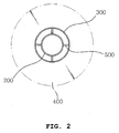
FIG. 2 is a plan view illustrating a connection unit provided between an air cooling member and an oxygen supplying member according to the present invention. - Exemplary embodiments of the present invention will be described herein below with reference to the accompanying drawings.
- An oxygen supplying apparatus of a melting furnace according to the present invention is inserted within the melting furnace, as shown in
FIG. 1 , and a connection unit is provided between an air cooling member and an oxygen supplying member, as shown inFIG. 2 . - As shown in
FIG. 1 , the oxygen supplying apparatus includes amelting furnace 100, anoxygen supplying member 200 and anair cooling member 300. - The
melting furnace 100 is formed in a cylindrical shape to receive radioactive and nonradioactive waste therein. - Specifically, the
melting furnace 100 includes a container for containing the waste to be melted and a cover for sealing the contained waste. - The
melting furnace 100 is provided with theoxygen supplying member 200 to supply oxygen to improve combustion of the waste contained within themelting furnace 100 or generates a bubble in the waste contained within themelting furnace 100 to uniformly melt the waste. - The
oxygen supplying member 200 is inserted to an interior of themelting furnace 100 by penetrating through athrough hole 110 formed on themelting furnace 100, wherein a diameter of theoxygen supplying member 200 is formed to be smaller than that of thethrough hole 110. - Specifically, the
oxygen supplying member 200 is formed to be elongated along a longitudinal direction to be longer than theair cooling member 300, which will be described below. A part of theoxygen supplying member 200 passes an upper portion of theair cooling member 300 to be exposed to an outside and another part of theoxygen supplying member 200 inserted to the interior of the meltingfurnace 100 passes a lower portion of theair cooling member 300. - The
oxygen supplying member 200 may be formed in a shape of a pipe that is open at both ends and comprise stainless steel. - Accordingly, the waste received in the melting
furnace 100 may be stirred by theoxygen supplying member 200, thereby increasing a processing capacity. - The
air cooling member 300 is provided in thethrough hole 110 formed on themelting furnace 100 and mounted on theoxygen supplying member 200 to allow an outside air to be entered thereto. - Specifically, the
air cooling member 300 is formed to have a diameter greater than that of theoxygen supplying member 200 and a part of theoxygen supplying member 200 is inserted within theair cooling member 300. - While the
oxygen supplying member 200 is inserted within theair cooling member 300, theoxygen supplying member 200 and theair cooling member 300 are connected to each other by using a plurality ofconnection units 500. - The
air cooling member 300 is formed to have an upper portion that is open and a lower portion that is closed by aclosing unit 310 such that the outside air is entered through the open upper portion thereof. - The air introduced to the
air cooling member 300 is circulated to cool theoxygen supplying member 200 inserted within themelting furnace 100. - Accordingly, the
oxygen supplying member 200 may maintain durability by using theair cooling member 300 even in an extreme circumstance of high temperature. - A fixing
member 400 is mounted and fixed to an upper portion of themelting furnace 100 and is provided at an outer surface of theair cooling member 300. - The fixing
member 400 comprises anupper fixing member 410 and alower fixing member 420 and is provided to surround the outer surface of theair cooling member 300. - The
lower fixing member 420 is mounted on the upper portion of themelting furnace 100 and thelower fixing member 420 is fixed to themelting furnace 100 by welding. - The
upper fixing member 410 is mounted on an upper portion of thelower fixing member 420, and a separate fixing bolt B is rotated to securely fix the upper fixingmember 410 to thelower fixing member 420. - An 0-ring, which is designated by a reference character "O" in
Fig. 1 , is interposed between the upper fixingmember 410 and thelower fixing member 420 to maintain sealing within themelting furnace 100. - Accordingly, the
air cooling member 300 is securely fixed by the fixingmember 400. - The
oxygen supplying member 200 is supported by using a plurality of theconnection units 500 positioned between theoxygen supplying member 200 and theair cooling member 300. - As shown in
FIG. 2 , by using theconnection unit 500, theair cooling member 300 and theoxygen supplying member 200 inserted within theair cooling member 300 are separated from each other to maintain a predetermined interval therebetween. - The
connection unit 500 is formed in a shape of a cylinder or a wide plate and is fixed to an inner surface of theair cooling member 300 and the outer surface of theoxygen supplying member 200. - Thus, a predetermined interval is maintained between the
oxygen supplying member 200 and theair cooling member 300 by theconnection unit 500 so that cooling by theair cooling member 300 is efficiently performed. - A condition of use and an operation of the oxygen supplying apparatus of the melting furnace that is configured as described above according to the present invention are described below.
- First, as shown in
FIGS. 1 and2 , themelting furnace 100 containing the waste to be vitrified, theoxygen supplying member 200, and theair cooling member 300 are standardized and modularized in a factory beforehand, thereby improving work efficiency at a work site. - The
melting furnace 100 containing the waste includes theair cooling member 300 provided in the throughhole 110 formed on themelting furnace 100 and theoxygen supplying member 200 that is modularized within theair cooling member 300. - The fixing
member 400 is mounted on the upper portion of themelting furnace 100 and surrounds the outer surface of theair cooling member 300. - The fixing
member 400 is mounted on themelting furnace 100 and is fastened to themelting furnace 100 by using the separate fixing bolt B. - By supplying oxygen into the
melting furnace 100 that is assembled as above, the waste may be efficiently melted. - According to the present invention, cooling is performed by an air cooling provided outside the air supplying apparatus, and thus the waste may be melted during a longer period by using the durability of the oxygen supplying apparatus.
- Also, economic damage due to wear and tear may be minimized by using a simplified structure, thereby improving reliability.
- In the above, although the embodiments of the present invention have been described with reference to the accompanying drawings, a person skilled in the art should apprehend that the present invention can be embodied in other specific forms. Thus, the embodiments described above should be construed as exemplary in every aspect and not limiting.
Claims (1)
- An oxygen supplying apparatus of a melting furnace (100), the oxygen supplying apparatus comprising:a through hole (110) formed in a wall of the melting furnace (100);an air cooling member (300) having a pipe shape, passing through the through hole (110) and extending inside and outside the melting furnace (100), the air cooling member (300) having a first end and a second end, the first end being open to an outside of the melting furnace (100) and allowing an outside air to enter into the air cooling member (300), the second end being closed in an inside of the melting furnace (100);an oxygen supplying member (200) having a pipe shape and passing through the air cooling member (300), the oxygen supplying member (200) being longer than the air cooling member (300) and having a first end and a second end, the first end of the oxygen supplying member (200) being open to introduce oxygen and extended out from the first end of the air cooling member (300), the second end of the oxygen supplying member (200) being open to the inside of the melting furnace (100) and extended out from the second end of the air cooling member (300), thereby allowing the oxygen to enter into the melting furnace (100);a plurality of connection units (500) positioned between the air cooling member (300) and the oxygen supplying member (200), the plurality of connection units (500) fixing the oxygen supplying member (200) in the air cooling member (300);a closing unit (310) provided in the second end of the air cooling member (300), the closing unit (310) closing an inside end of a space between an inner surface of the air cooling member (300) and an outer surface of the oxygen supplying member (200) such that the outside air entered into the space through the first end of the air cooling member (300) circulates in the space;a lower fixing member (420) mounted on an outer surface of the melting furnace (100), fixed on the outer surface of the melting furnace (100) by a welding and having a hole in a center, the hole of the lower fixing member (420) having a diameter greater than a diameter of the air cooling member (300) such that an outer surface of the air cooling member (300) does not directly contact with the inner surface of the hole of the lower fixing member (420), the hole of the lower fixing member (420) being arranged to have the same central axis with the through hole (110) of the melting furnace (100); andan upper fixing member (410) mounted on the lower fixing member (420), fixed on the lower fixing member (420) by a bolt (B) and having a hole in a center, the upper fixing member (410) fixing the air cooling member (300) in the hole of the upper fixing member (410);a ring (O) interposed between the lower fixing member (420) and the upper fixing member (410) to seal the melting furnace (100);wherein a diameter of the through hole (110) of the wall of the melting furnace (100) is greater than the diameter of the air cooling member (300) such that the outer surface of the air cooling member (300) does not directly contact with the inner surface of the through hole (110) of the wall of the melting furnace (100); andwherein the space between the inner surface of the air cooling member (300) and the outer surface of the oxygen supplying member (200) includes only the connection units (500), and the oxygen supplying member (200) includes nothing thereinside.
Applications Claiming Priority (1)
| Application Number | Priority Date | Filing Date | Title |
|---|---|---|---|
| KR1020110094291A KR101248940B1 (en) | 2011-09-19 | 2011-09-19 | Crucible of a oxygen suppling apparatus |
Publications (3)
| Publication Number | Publication Date |
|---|---|
| EP2570725A2 EP2570725A2 (en) | 2013-03-20 |
| EP2570725A3 EP2570725A3 (en) | 2015-03-18 |
| EP2570725B1 true EP2570725B1 (en) | 2016-11-02 |
Family
ID=46396984
Family Applications (1)
| Application Number | Title | Priority Date | Filing Date |
|---|---|---|---|
| EP12166799.2A Active EP2570725B1 (en) | 2011-09-19 | 2012-05-04 | Oxygen supplying apparatus of a melting furnace |
Country Status (4)
| Country | Link |
|---|---|
| US (1) | US8770118B2 (en) |
| EP (1) | EP2570725B1 (en) |
| JP (1) | JP5659184B2 (en) |
| KR (1) | KR101248940B1 (en) |
Family Cites Families (24)
| Publication number | Priority date | Publication date | Assignee | Title |
|---|---|---|---|---|
| US2828956A (en) * | 1954-10-01 | 1958-04-01 | Union Carbide Corp | Top blowing oxygen nozzle in molten metal |
| US3488044A (en) * | 1967-05-01 | 1970-01-06 | Nat Steel Corp | Apparatus for refining metal |
| US3703279A (en) * | 1969-08-15 | 1972-11-21 | Joslyn Mfg & Supply Co | Reactor |
| DE2118409A1 (en) * | 1971-04-16 | 1973-04-12 | Messer Griesheim Gmbh | BURNER |
| FR2238395A5 (en) * | 1973-07-17 | 1975-02-14 | Est Aciers Fins | |
| US4023676A (en) * | 1976-09-20 | 1977-05-17 | Armco Steel Corporation | Lance structure and method for oxygen refining of molten metal |
| JPS6045685B2 (en) * | 1981-12-11 | 1985-10-11 | 新日本製鐵株式会社 | Double pipe tuyere for bottom blowing |
| US4449701A (en) * | 1982-08-23 | 1984-05-22 | Pennsylvania Engineering Corporation | Tuyere for the injection of gases into a metallurgical vessel |
| US4550898A (en) * | 1984-06-04 | 1985-11-05 | Labate Ii Michael D | Air cooled refractory lance |
| DE3508618A1 (en) * | 1985-03-29 | 1986-09-18 | Vasipari Kutató és Fejlesztö Vállalat, Budapest | BLOWING TREATMENT FOR TREATING METAL MELT IN MILL PLANTS |
| JPS61198253U (en) * | 1985-05-27 | 1986-12-11 | ||
| US4941646A (en) * | 1988-11-23 | 1990-07-17 | Bethlehem Steel Corporation | Air cooled gas injection lance |
| US5217363A (en) * | 1992-06-03 | 1993-06-08 | Gaz Metropolitan & Co., Ltd. And Partnership | Air-cooled oxygen gas burner assembly |
| US5267850A (en) * | 1992-06-04 | 1993-12-07 | Praxair Technology, Inc. | Fuel jet burner |
| US5443572A (en) * | 1993-12-03 | 1995-08-22 | Molten Metal Technology, Inc. | Apparatus and method for submerged injection of a feed composition into a molten metal bath |
| JPH10245618A (en) * | 1997-03-06 | 1998-09-14 | Arco Ind Kk | Oxygen blowing device |
| US5904475A (en) * | 1997-05-08 | 1999-05-18 | Praxair Technology, Inc. | Dual oxidant combustion system |
| DE19755876C2 (en) * | 1997-12-04 | 2000-02-24 | Mannesmann Ag | Blow lance for treating metallic melts and method for blowing in gases |
| US6576807B1 (en) * | 1998-12-01 | 2003-06-10 | Société Générale pour les Techniques Nouvelles-SGN | Method and apparatus for incinerating and vitrifying of waste, in particular radioactive waste |
| AUPQ308799A0 (en) * | 1999-09-27 | 1999-10-21 | Technological Resources Pty Limited | A direct smelting process |
| KR100392503B1 (en) * | 2000-12-20 | 2003-08-19 | 한국수력원자력 주식회사 | Method for Start-up of Glass Using Resistance Heater in Cold Crucible Melter Combustible Low and Intermediate - Level Radioactive Waste |
| KR100498881B1 (en) | 2002-06-07 | 2005-07-04 | 현대모비스 주식회사 | treatment apparatus for destroying by burning up and melting radioactive waste and method the same |
| KR200294861Y1 (en) | 2002-06-07 | 2002-11-13 | 현대모비스 주식회사 | treatment apparatus for destroying by burning up and melting radioactive waste |
| KR100611358B1 (en) * | 2004-11-24 | 2006-08-11 | 한국수력원자력 주식회사 | Waste Metal Vitrification Apparatus and Method |
-
2011
- 2011-09-19 KR KR1020110094291A patent/KR101248940B1/en active Active
-
2012
- 2012-04-05 JP JP2012086265A patent/JP5659184B2/en active Active
- 2012-05-04 EP EP12166799.2A patent/EP2570725B1/en active Active
- 2012-05-08 US US13/466,294 patent/US8770118B2/en active Active
Also Published As
| Publication number | Publication date |
|---|---|
| JP2013064720A (en) | 2013-04-11 |
| EP2570725A2 (en) | 2013-03-20 |
| KR20130030671A (en) | 2013-03-27 |
| EP2570725A3 (en) | 2015-03-18 |
| JP5659184B2 (en) | 2015-01-28 |
| US8770118B2 (en) | 2014-07-08 |
| KR101248940B1 (en) | 2013-04-01 |
| US20130068420A1 (en) | 2013-03-21 |
Similar Documents
| Publication | Publication Date | Title |
|---|---|---|
| LU102098B1 (en) | Blast furnace with shaft feeding of hot process gas | |
| US20090129428A1 (en) | Cooling device for use in an electric arc furnace | |
| US8142711B2 (en) | Forged copper burner enclosure | |
| US20200333075A1 (en) | Fluid cooled housing system for instruments of a metal making furnace | |
| EP1170386A2 (en) | Injection lance, particularly for injecting substances in the form of powder or particulate, into electric furnaces for steelmaking | |
| LU102096B1 (en) | Exchangeable cooled nose with ceramic injector passage | |
| CN215447495U (en) | Flue gas rapid cooling processing apparatus | |
| CN215725068U (en) | A multi-functional clean energy stove for rock wool production | |
| WO2008047979A1 (en) | Tuyere of melter-gasifier | |
| CN210441657U (en) | Nozzle assemblies and reactors for reactors | |
| BRPI1100201A2 (en) | Vacuum circulating degassing system with pilot burner | |
| WO1997002365A1 (en) | Device for after-burning combustible components of the atmosphere in metallurgical smelting vessels | |
| EP0871785B1 (en) | Method and apparatus for after-burning the combustible components of the atmosphere in metallurgical smelting vessels | |
| CN112050649B (en) | Nozzle assembly for reactor and reactor | |
| CN112050650B (en) | Nozzle assembly for reactor and reactor | |
| CN222187821U (en) | Cold material mouth water jacket for fuming furnace | |
| CN217785844U (en) | Top-blown furnace spray gun cooling device | |
| CN207958280U (en) | A kind of head uses the blast orifice oxygen burner of impinging cooling | |
| EA045788B1 (en) | BLAST FURNACE WITH HOT PROCESS GAS SUPPLY TO THE MINE | |
| CN112044359B (en) | Spraying device for reactor and reactor | |
| US5916512A (en) | Method and apparatus for after-burning the combustible components of the atmosphere in metallurgical smelting vessels | |
| US8770118B2 (en) | Oxygen supplying apparatus of a melting furnace | |
| JPH0329318Y2 (en) | ||
| KR20080004171A (en) | Installation structure of top burner supporting burner in electric furnace |
Legal Events
| Date | Code | Title | Description |
|---|---|---|---|
| PUAI | Public reference made under article 153(3) epc to a published international application that has entered the european phase |
Free format text: ORIGINAL CODE: 0009012 |
|
| AK | Designated contracting states |
Kind code of ref document: A2 Designated state(s): AL AT BE BG CH CY CZ DE DK EE ES FI FR GB GR HR HU IE IS IT LI LT LU LV MC MK MT NL NO PL PT RO RS SE SI SK SM TR |
|
| AX | Request for extension of the european patent |
Extension state: BA ME |
|
| PUAL | Search report despatched |
Free format text: ORIGINAL CODE: 0009013 |
|
| AK | Designated contracting states |
Kind code of ref document: A3 Designated state(s): AL AT BE BG CH CY CZ DE DK EE ES FI FR GB GR HR HU IE IS IT LI LT LU LV MC MK MT NL NO PL PT RO RS SE SI SK SM TR |
|
| AX | Request for extension of the european patent |
Extension state: BA ME |
|
| RIC1 | Information provided on ipc code assigned before grant |
Ipc: F23L 7/00 20060101AFI20150209BHEP |
|
| 17P | Request for examination filed |
Effective date: 20150908 |
|
| RBV | Designated contracting states (corrected) |
Designated state(s): AL AT BE BG CH CY CZ DE DK EE ES FI FR GB GR HR HU IE IS IT LI LT LU LV MC MK MT NL NO PL PT RO RS SE SI SK SM TR |
|
| GRAP | Despatch of communication of intention to grant a patent |
Free format text: ORIGINAL CODE: EPIDOSNIGR1 |
|
| GRAJ | Information related to disapproval of communication of intention to grant by the applicant or resumption of examination proceedings by the epo deleted |
Free format text: ORIGINAL CODE: EPIDOSDIGR1 |
|
| GRAP | Despatch of communication of intention to grant a patent |
Free format text: ORIGINAL CODE: EPIDOSNIGR1 |
|
| INTG | Intention to grant announced |
Effective date: 20160512 |
|
| INTG | Intention to grant announced |
Effective date: 20160523 |
|
| GRAS | Grant fee paid |
Free format text: ORIGINAL CODE: EPIDOSNIGR3 |
|
| GRAA | (expected) grant |
Free format text: ORIGINAL CODE: 0009210 |
|
| AK | Designated contracting states |
Kind code of ref document: B1 Designated state(s): AL AT BE BG CH CY CZ DE DK EE ES FI FR GB GR HR HU IE IS IT LI LT LU LV MC MK MT NL NO PL PT RO RS SE SI SK SM TR |
|
| REG | Reference to a national code |
Ref country code: GB Ref legal event code: FG4D |
|
| REG | Reference to a national code |
Ref country code: AT Ref legal event code: REF Ref document number: 842226 Country of ref document: AT Kind code of ref document: T Effective date: 20161115 Ref country code: CH Ref legal event code: EP |
|
| REG | Reference to a national code |
Ref country code: IE Ref legal event code: FG4D |
|
| REG | Reference to a national code |
Ref country code: DE Ref legal event code: R096 Ref document number: 602012024751 Country of ref document: DE |
|
| PG25 | Lapsed in a contracting state [announced via postgrant information from national office to epo] |
Ref country code: LV Free format text: LAPSE BECAUSE OF FAILURE TO SUBMIT A TRANSLATION OF THE DESCRIPTION OR TO PAY THE FEE WITHIN THE PRESCRIBED TIME-LIMIT Effective date: 20161102 |
|
| REG | Reference to a national code |
Ref country code: NL Ref legal event code: MP Effective date: 20161102 |
|
| REG | Reference to a national code |
Ref country code: LT Ref legal event code: MG4D |
|
| REG | Reference to a national code |
Ref country code: AT Ref legal event code: MK05 Ref document number: 842226 Country of ref document: AT Kind code of ref document: T Effective date: 20161102 |
|
| PG25 | Lapsed in a contracting state [announced via postgrant information from national office to epo] |
Ref country code: NO Free format text: LAPSE BECAUSE OF FAILURE TO SUBMIT A TRANSLATION OF THE DESCRIPTION OR TO PAY THE FEE WITHIN THE PRESCRIBED TIME-LIMIT Effective date: 20170202 Ref country code: GR Free format text: LAPSE BECAUSE OF FAILURE TO SUBMIT A TRANSLATION OF THE DESCRIPTION OR TO PAY THE FEE WITHIN THE PRESCRIBED TIME-LIMIT Effective date: 20170203 Ref country code: SE Free format text: LAPSE BECAUSE OF FAILURE TO SUBMIT A TRANSLATION OF THE DESCRIPTION OR TO PAY THE FEE WITHIN THE PRESCRIBED TIME-LIMIT Effective date: 20161102 Ref country code: NL Free format text: LAPSE BECAUSE OF FAILURE TO SUBMIT A TRANSLATION OF THE DESCRIPTION OR TO PAY THE FEE WITHIN THE PRESCRIBED TIME-LIMIT Effective date: 20161102 Ref country code: LT Free format text: LAPSE BECAUSE OF FAILURE TO SUBMIT A TRANSLATION OF THE DESCRIPTION OR TO PAY THE FEE WITHIN THE PRESCRIBED TIME-LIMIT Effective date: 20161102 |
|
| PG25 | Lapsed in a contracting state [announced via postgrant information from national office to epo] |
Ref country code: RS Free format text: LAPSE BECAUSE OF FAILURE TO SUBMIT A TRANSLATION OF THE DESCRIPTION OR TO PAY THE FEE WITHIN THE PRESCRIBED TIME-LIMIT Effective date: 20161102 Ref country code: PT Free format text: LAPSE BECAUSE OF FAILURE TO SUBMIT A TRANSLATION OF THE DESCRIPTION OR TO PAY THE FEE WITHIN THE PRESCRIBED TIME-LIMIT Effective date: 20170302 Ref country code: IS Free format text: LAPSE BECAUSE OF FAILURE TO SUBMIT A TRANSLATION OF THE DESCRIPTION OR TO PAY THE FEE WITHIN THE PRESCRIBED TIME-LIMIT Effective date: 20170302 Ref country code: HR Free format text: LAPSE BECAUSE OF FAILURE TO SUBMIT A TRANSLATION OF THE DESCRIPTION OR TO PAY THE FEE WITHIN THE PRESCRIBED TIME-LIMIT Effective date: 20161102 Ref country code: PL Free format text: LAPSE BECAUSE OF FAILURE TO SUBMIT A TRANSLATION OF THE DESCRIPTION OR TO PAY THE FEE WITHIN THE PRESCRIBED TIME-LIMIT Effective date: 20161102 Ref country code: ES Free format text: LAPSE BECAUSE OF FAILURE TO SUBMIT A TRANSLATION OF THE DESCRIPTION OR TO PAY THE FEE WITHIN THE PRESCRIBED TIME-LIMIT Effective date: 20161102 Ref country code: AT Free format text: LAPSE BECAUSE OF FAILURE TO SUBMIT A TRANSLATION OF THE DESCRIPTION OR TO PAY THE FEE WITHIN THE PRESCRIBED TIME-LIMIT Effective date: 20161102 |
|
| PG25 | Lapsed in a contracting state [announced via postgrant information from national office to epo] |
Ref country code: EE Free format text: LAPSE BECAUSE OF FAILURE TO SUBMIT A TRANSLATION OF THE DESCRIPTION OR TO PAY THE FEE WITHIN THE PRESCRIBED TIME-LIMIT Effective date: 20161102 Ref country code: RO Free format text: LAPSE BECAUSE OF FAILURE TO SUBMIT A TRANSLATION OF THE DESCRIPTION OR TO PAY THE FEE WITHIN THE PRESCRIBED TIME-LIMIT Effective date: 20161102 Ref country code: CZ Free format text: LAPSE BECAUSE OF FAILURE TO SUBMIT A TRANSLATION OF THE DESCRIPTION OR TO PAY THE FEE WITHIN THE PRESCRIBED TIME-LIMIT Effective date: 20161102 Ref country code: DK Free format text: LAPSE BECAUSE OF FAILURE TO SUBMIT A TRANSLATION OF THE DESCRIPTION OR TO PAY THE FEE WITHIN THE PRESCRIBED TIME-LIMIT Effective date: 20161102 Ref country code: SK Free format text: LAPSE BECAUSE OF FAILURE TO SUBMIT A TRANSLATION OF THE DESCRIPTION OR TO PAY THE FEE WITHIN THE PRESCRIBED TIME-LIMIT Effective date: 20161102 |
|
| REG | Reference to a national code |
Ref country code: DE Ref legal event code: R097 Ref document number: 602012024751 Country of ref document: DE |
|
| PG25 | Lapsed in a contracting state [announced via postgrant information from national office to epo] |
Ref country code: BG Free format text: LAPSE BECAUSE OF FAILURE TO SUBMIT A TRANSLATION OF THE DESCRIPTION OR TO PAY THE FEE WITHIN THE PRESCRIBED TIME-LIMIT Effective date: 20170202 Ref country code: LU Free format text: LAPSE BECAUSE OF NON-PAYMENT OF DUE FEES Effective date: 20170531 Ref country code: SM Free format text: LAPSE BECAUSE OF FAILURE TO SUBMIT A TRANSLATION OF THE DESCRIPTION OR TO PAY THE FEE WITHIN THE PRESCRIBED TIME-LIMIT Effective date: 20161102 Ref country code: IT Free format text: LAPSE BECAUSE OF FAILURE TO SUBMIT A TRANSLATION OF THE DESCRIPTION OR TO PAY THE FEE WITHIN THE PRESCRIBED TIME-LIMIT Effective date: 20161102 Ref country code: BE Free format text: LAPSE BECAUSE OF FAILURE TO SUBMIT A TRANSLATION OF THE DESCRIPTION OR TO PAY THE FEE WITHIN THE PRESCRIBED TIME-LIMIT Effective date: 20161102 |
|
| PLBE | No opposition filed within time limit |
Free format text: ORIGINAL CODE: 0009261 |
|
| STAA | Information on the status of an ep patent application or granted ep patent |
Free format text: STATUS: NO OPPOSITION FILED WITHIN TIME LIMIT |
|
| 26N | No opposition filed |
Effective date: 20170803 |
|
| PG25 | Lapsed in a contracting state [announced via postgrant information from national office to epo] |
Ref country code: SI Free format text: LAPSE BECAUSE OF FAILURE TO SUBMIT A TRANSLATION OF THE DESCRIPTION OR TO PAY THE FEE WITHIN THE PRESCRIBED TIME-LIMIT Effective date: 20161102 |
|
| REG | Reference to a national code |
Ref country code: DE Ref legal event code: R119 Ref document number: 602012024751 Country of ref document: DE |
|
| PG25 | Lapsed in a contracting state [announced via postgrant information from national office to epo] |
Ref country code: MC Free format text: LAPSE BECAUSE OF FAILURE TO SUBMIT A TRANSLATION OF THE DESCRIPTION OR TO PAY THE FEE WITHIN THE PRESCRIBED TIME-LIMIT Effective date: 20161102 |
|
| REG | Reference to a national code |
Ref country code: IE Ref legal event code: MM4A |
|
| REG | Reference to a national code |
Ref country code: FR Ref legal event code: ST Effective date: 20180131 |
|
| PG25 | Lapsed in a contracting state [announced via postgrant information from national office to epo] |
Ref country code: LU Free format text: LAPSE BECAUSE OF NON-PAYMENT OF DUE FEES Effective date: 20170504 |
|
| PG25 | Lapsed in a contracting state [announced via postgrant information from national office to epo] |
Ref country code: IE Free format text: LAPSE BECAUSE OF NON-PAYMENT OF DUE FEES Effective date: 20170504 Ref country code: DE Free format text: LAPSE BECAUSE OF NON-PAYMENT OF DUE FEES Effective date: 20171201 |
|
| PG25 | Lapsed in a contracting state [announced via postgrant information from national office to epo] |
Ref country code: FR Free format text: LAPSE BECAUSE OF NON-PAYMENT OF DUE FEES Effective date: 20170531 |
|
| PG25 | Lapsed in a contracting state [announced via postgrant information from national office to epo] |
Ref country code: MT Free format text: LAPSE BECAUSE OF NON-PAYMENT OF DUE FEES Effective date: 20170504 |
|
| PG25 | Lapsed in a contracting state [announced via postgrant information from national office to epo] |
Ref country code: HU Free format text: LAPSE BECAUSE OF FAILURE TO SUBMIT A TRANSLATION OF THE DESCRIPTION OR TO PAY THE FEE WITHIN THE PRESCRIBED TIME-LIMIT; INVALID AB INITIO Effective date: 20120504 |
|
| PG25 | Lapsed in a contracting state [announced via postgrant information from national office to epo] |
Ref country code: CY Free format text: LAPSE BECAUSE OF NON-PAYMENT OF DUE FEES Effective date: 20161102 |
|
| PG25 | Lapsed in a contracting state [announced via postgrant information from national office to epo] |
Ref country code: MK Free format text: LAPSE BECAUSE OF FAILURE TO SUBMIT A TRANSLATION OF THE DESCRIPTION OR TO PAY THE FEE WITHIN THE PRESCRIBED TIME-LIMIT Effective date: 20161102 |
|
| PG25 | Lapsed in a contracting state [announced via postgrant information from national office to epo] |
Ref country code: TR Free format text: LAPSE BECAUSE OF FAILURE TO SUBMIT A TRANSLATION OF THE DESCRIPTION OR TO PAY THE FEE WITHIN THE PRESCRIBED TIME-LIMIT Effective date: 20161102 |
|
| PG25 | Lapsed in a contracting state [announced via postgrant information from national office to epo] |
Ref country code: AL Free format text: LAPSE BECAUSE OF FAILURE TO SUBMIT A TRANSLATION OF THE DESCRIPTION OR TO PAY THE FEE WITHIN THE PRESCRIBED TIME-LIMIT Effective date: 20161102 |
|
| PGFP | Annual fee paid to national office [announced via postgrant information from national office to epo] |
Ref country code: FI Payment date: 20250513 Year of fee payment: 14 |
|
| PGFP | Annual fee paid to national office [announced via postgrant information from national office to epo] |
Ref country code: GB Payment date: 20250501 Year of fee payment: 14 |
|
| PGFP | Annual fee paid to national office [announced via postgrant information from national office to epo] |
Ref country code: CH Payment date: 20250601 Year of fee payment: 14 |