EP2570653A1 - Convertible wind turbine nacelle cover - Google Patents
Convertible wind turbine nacelle cover Download PDFInfo
- Publication number
- EP2570653A1 EP2570653A1 EP11382297A EP11382297A EP2570653A1 EP 2570653 A1 EP2570653 A1 EP 2570653A1 EP 11382297 A EP11382297 A EP 11382297A EP 11382297 A EP11382297 A EP 11382297A EP 2570653 A1 EP2570653 A1 EP 2570653A1
- Authority
- EP
- European Patent Office
- Prior art keywords
- cover
- wind turbine
- platform
- nacelle cover
- nacelle
- Prior art date
- Legal status (The legal status is an assumption and is not a legal conclusion. Google has not performed a legal analysis and makes no representation as to the accuracy of the status listed.)
- Granted
Links
- 238000012423 maintenance Methods 0.000 claims abstract description 14
- 230000000694 effects Effects 0.000 description 1
Images


Classifications
-
- F—MECHANICAL ENGINEERING; LIGHTING; HEATING; WEAPONS; BLASTING
- F03—MACHINES OR ENGINES FOR LIQUIDS; WIND, SPRING, OR WEIGHT MOTORS; PRODUCING MECHANICAL POWER OR A REACTIVE PROPULSIVE THRUST, NOT OTHERWISE PROVIDED FOR
- F03D—WIND MOTORS
- F03D80/00—Details, components or accessories not provided for in groups F03D1/00 - F03D17/00
- F03D80/50—Maintenance or repair
-
- F—MECHANICAL ENGINEERING; LIGHTING; HEATING; WEAPONS; BLASTING
- F03—MACHINES OR ENGINES FOR LIQUIDS; WIND, SPRING, OR WEIGHT MOTORS; PRODUCING MECHANICAL POWER OR A REACTIVE PROPULSIVE THRUST, NOT OTHERWISE PROVIDED FOR
- F03D—WIND MOTORS
- F03D80/00—Details, components or accessories not provided for in groups F03D1/00 - F03D17/00
-
- F—MECHANICAL ENGINEERING; LIGHTING; HEATING; WEAPONS; BLASTING
- F05—INDEXING SCHEMES RELATING TO ENGINES OR PUMPS IN VARIOUS SUBCLASSES OF CLASSES F01-F04
- F05B—INDEXING SCHEME RELATING TO WIND, SPRING, WEIGHT, INERTIA OR LIKE MOTORS, TO MACHINES OR ENGINES FOR LIQUIDS COVERED BY SUBCLASSES F03B, F03D AND F03G
- F05B2230/00—Manufacture
- F05B2230/80—Repairing, retrofitting or upgrading methods
-
- F—MECHANICAL ENGINEERING; LIGHTING; HEATING; WEAPONS; BLASTING
- F05—INDEXING SCHEMES RELATING TO ENGINES OR PUMPS IN VARIOUS SUBCLASSES OF CLASSES F01-F04
- F05B—INDEXING SCHEME RELATING TO WIND, SPRING, WEIGHT, INERTIA OR LIKE MOTORS, TO MACHINES OR ENGINES FOR LIQUIDS COVERED BY SUBCLASSES F03B, F03D AND F03G
- F05B2240/00—Components
- F05B2240/10—Stators
- F05B2240/14—Casings, housings, nacelles, gondels or the like, protecting or supporting assemblies there within
-
- Y—GENERAL TAGGING OF NEW TECHNOLOGICAL DEVELOPMENTS; GENERAL TAGGING OF CROSS-SECTIONAL TECHNOLOGIES SPANNING OVER SEVERAL SECTIONS OF THE IPC; TECHNICAL SUBJECTS COVERED BY FORMER USPC CROSS-REFERENCE ART COLLECTIONS [XRACs] AND DIGESTS
- Y02—TECHNOLOGIES OR APPLICATIONS FOR MITIGATION OR ADAPTATION AGAINST CLIMATE CHANGE
- Y02E—REDUCTION OF GREENHOUSE GAS [GHG] EMISSIONS, RELATED TO ENERGY GENERATION, TRANSMISSION OR DISTRIBUTION
- Y02E10/00—Energy generation through renewable energy sources
- Y02E10/70—Wind energy
- Y02E10/72—Wind turbines with rotation axis in wind direction
-
- Y—GENERAL TAGGING OF NEW TECHNOLOGICAL DEVELOPMENTS; GENERAL TAGGING OF CROSS-SECTIONAL TECHNOLOGIES SPANNING OVER SEVERAL SECTIONS OF THE IPC; TECHNICAL SUBJECTS COVERED BY FORMER USPC CROSS-REFERENCE ART COLLECTIONS [XRACs] AND DIGESTS
- Y02—TECHNOLOGIES OR APPLICATIONS FOR MITIGATION OR ADAPTATION AGAINST CLIMATE CHANGE
- Y02P—CLIMATE CHANGE MITIGATION TECHNOLOGIES IN THE PRODUCTION OR PROCESSING OF GOODS
- Y02P70/00—Climate change mitigation technologies in the production process for final industrial or consumer products
- Y02P70/50—Manufacturing or production processes characterised by the final manufactured product
Definitions
- the present invention relates to wind turbines, especially to small and mid power machines, which size frequently makes it not possible to gain access and perform maintenance operations inside the nacelle.
- Wind energy is one of the more extended renewable energy resources. This kind of energy easily covers a wide power range with reduced costs.
- the nacelle of large turbines is reached by means of a ladder or, more commonly, an elevator inside the tower, and once there the maintenance operations can be conveniently performed since the space inside the nacelle cover is enough to work.
- the tower is too small to allow an elevator inside, and the only way to access the nacelle through the tower is by means of a ladder fixed outside of it, although in the bigger designs sometimes the ladder can be placed inside.
- a second problem once the worker has climbed to the tower top is that he has not an adequate and safe place to stand while performing the maintenance operations, with good access to the nacelle components.
- the nacelle cover has to be removed to reach the elements of the wind turbine equipment.
- the present invention relates to a convertible wind turbine nacelle cover which consists on a new concept, named "convertible nacelle cover”.
- the present invention allows operators to work on the nacelle components of a wind turbine minimizing the attachments to the turbine and avoiding the use of lifting platforms.
- the nacelle When the turbine is in operation, the nacelle is in a closed position, so the cover forms a closed envelope as in standard turbines, with all its parts joined together in contact.
- the nacelle cover can be opened, separating the cover parts from each other, in such a way that a platform, which is integrated in one of those parts, is accessible, so an operator can stand on it and perform the mentioned operations.
- the nacelle cover comprises at least two parts being the working platform integrated in one of said parts. This is the most important feature of the present invention.
- the working platform is integrated in the nacelle cover so it is the nacelle cover per se the place where the operators work.
- the convertible wind nacelle cover of the present invention comprises at least two parts which are in direct contact when the cover is in a closed position and which can be moved to open the cover.
- One of said at least two parts has a working platform integrated on it so when the cover is opened the maintenance operations can be performed from the working platform which is part of the cover.
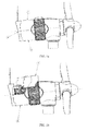
- the convertible nacelle cover comprises three parts which are an upper part (1), a lower part (2) and a rear part (3) ( figure 1a ), arranged in a way that the opened position of the nacelle cover is reached moving up the upper part ( figure 1b ) and moving down the lower part (2) ( figure 1c ).
- the rear part (3) which integrates the working platform, is opened pivoting around a horizontal axis until the platform integrated on said rear part (3) reaches a horizontal position ( figure 1d ).
- the convertible nacelle cover comprises three parts which are a right part (4), a left part (5) and a third part (6) ( figure 2a ), arranged in such a way that the opened position of the nacelle cover is reached pivoting the right part (4) and the left part (5) around an axis located on the top of the nacelle ( figure 2b ).
- the third part (6) which integrates the working platform, is opened pivoting around a horizontal axis until the platform integrated on said rear part reaches a horizontal position ( figure 2c ).
- the convertible nacelle cover of the present invention When the nacelle cover of the present invention is in an opened position, the convertible nacelle cover is closed following the inverse sequence than the opening sequence.
- the relative movements of the cover parts can be achieved by linear actuators or rotary motors conveniently integrated with the mechanism structure.
- the actuators or motors can be driven electrically (AC or DC), hydraulically, pneumatically, by springs or even manually.
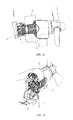
- Figure 3 shows a possible configuration of the present invention. As can be seen from figure 3 , actuators (7) can be used for the cover parts movement.
- hatches (8, 9) can be included in the present invention in the part of the cover which has the working platform.
- the hatches are especially useful in cases where the access to the working platform is allowed from below.
- the operator opens the hatch (8) placed in the outside of the cover and passes to the working platform.
- the hatch (9) placed in the working platform so he can stay safely in the platform.
- the hatches would not be necessary.
- security anchors 10
- These anchors can be included in the cover or platform itself and/or directly on the turbine structure, ensuring that the worker can reach them.
- Safety can also be increased by means of a handrail (11), embodied with the working platform, which can be either fixed, or partially or completely removable.
- the invention can also include some devices to fix the cover parts together, avoiding any movement between them when the convertible cover is closed, like for instance security locks (12) in which a bolt (13) is trapped when the cover parts are together.
- these locking devices shall be operated remotely, as well as the linear actuators or motors, ensuring that they are opened before the opening movement of the cover starts.
- the maintenance works on the wind turbine nacelle sensors can be enhanced if these sensors are placed on a support (14) which is placed in the rear part of the cover, fixed by means of a hinge mechanism, which allows turning it when the worker is on the platform, as shown in figure 3 .
Landscapes
- Engineering & Computer Science (AREA)
- Life Sciences & Earth Sciences (AREA)
- Sustainable Development (AREA)
- Sustainable Energy (AREA)
- Chemical & Material Sciences (AREA)
- Combustion & Propulsion (AREA)
- Mechanical Engineering (AREA)
- General Engineering & Computer Science (AREA)
- Wind Motors (AREA)
- Movable Scaffolding (AREA)
Abstract
Description
- The present invention relates to wind turbines, especially to small and mid power machines, which size frequently makes it not possible to gain access and perform maintenance operations inside the nacelle.
- Wind energy is one of the more extended renewable energy resources. This kind of energy easily covers a wide power range with reduced costs.
- Nowadays, the most common application of wind energy is the utility-scale generation by means of wind farms consisting on several large turbines, each one with a power of at least 800 kW. However, a newer and promising application is the use of small and medium size turbines (normally below 500 kW) in distributed generation.
- The size of these turbines allows placing them near to the point where the generated energy will be used. In those cases it is not necessary a transport grid. The use of small and medium size turbines makes it possible to generate renewable energy at low cost close to factories or industrial areas, for example.
- For the reasons above, the development of small and medium size wind turbines is increasing nowadays.
- One difficulty in small and medium turbines is that their relatively small size makes it impossible to apply the usual solutions of large wind turbines to allow the maintenance personnel both accessing and working on the components of the nacelle.
- Indeed, the nacelle of large turbines is reached by means of a ladder or, more commonly, an elevator inside the tower, and once there the maintenance operations can be conveniently performed since the space inside the nacelle cover is enough to work.
- However, in most small and medium wind turbines, the tower is too small to allow an elevator inside, and the only way to access the nacelle through the tower is by means of a ladder fixed outside of it, although in the bigger designs sometimes the ladder can be placed inside.
- Moreover, a second problem once the worker has climbed to the tower top, is that he has not an adequate and safe place to stand while performing the maintenance operations, with good access to the nacelle components.
- To solve this problem, many small and medium size wind turbines are equipped with a platform at the top of the tower, just below the yaw gear, which is reached by means of the mentioned ladder (in case of inside ladders, a door is provided at the top of the tower). Standing there, the worker removes the cover to operate on the components, a difficult job due to the small size of the platform (limited by the overhang distance between tower and blades) and, especially in the case of bigger designs, because some of the parts can be hardly reached from the working position. On the other hand, this fixed platform affects negatively to the aesthetics of the turbine and can even induce a shadow effect on the rotor when the turbine is turning, increasing loads.
- In other small and medium size wind turbines, lifting platforms or cranes must be used to reach and work on the nacelle components during maintenance, increasing the O&M costs and adding the problem of the limited availability of these devices. Finally, in some turbines the nacelle has to be brought down in order to perform the maintenance operations on the ground, a complex and time-consuming practice, especially in the bigger turbines of this range.
- In all cases, the nacelle cover has to be removed to reach the elements of the wind turbine equipment.
- The present invention relates to a convertible wind turbine nacelle cover which consists on a new concept, named "convertible nacelle cover". The present invention allows operators to work on the nacelle components of a wind turbine minimizing the attachments to the turbine and avoiding the use of lifting platforms.
- When the turbine is in operation, the nacelle is in a closed position, so the cover forms a closed envelope as in standard turbines, with all its parts joined together in contact. When it is necessary to perform maintenance operations in the nacelle, the nacelle cover can be opened, separating the cover parts from each other, in such a way that a platform, which is integrated in one of those parts, is accessible, so an operator can stand on it and perform the mentioned operations.
- The nacelle cover comprises at least two parts being the working platform integrated in one of said parts. This is the most important feature of the present invention. The working platform is integrated in the nacelle cover so it is the nacelle cover per se the place where the operators work.
-
-
Figure 1 shows one of the preferred embodiments, in which the cover includes three parts where an upper part and a lower part are moved towards the front of the turbine, allowing the rear part to turn. Infigures 1a to 1d the movements of the parts of the cover are represented and it is shown the sequence to open the cover of the represented embodiment. -
Figure 2 shows another embodiment of the invention, in which the cover has a left and a right part which are opened upwards, and a third part which turns to open. Infigures 2a to 2c the movements of the parts of the cover are represented and it is shown the sequence to open the cover of the represented embodiment. -
Figure 3 shows a view of an embodiment of the present invention. - The convertible wind nacelle cover of the present invention comprises at least two parts which are in direct contact when the cover is in a closed position and which can be moved to open the cover. One of said at least two parts has a working platform integrated on it so when the cover is opened the maintenance operations can be performed from the working platform which is part of the cover.
- In a first embodiment of the invention (
figure 1 ), the convertible nacelle cover comprises three parts which are an upper part (1), a lower part (2) and a rear part (3) (figure 1a ), arranged in a way that the opened position of the nacelle cover is reached moving up the upper part (figure 1b ) and moving down the lower part (2) (figure 1c ). Once these two parts are opened, the rear part (3), which integrates the working platform, is opened pivoting around a horizontal axis until the platform integrated on said rear part (3) reaches a horizontal position (figure 1d ). - In another embodiment of the invention (
figure 2 ), the convertible nacelle cover comprises three parts which are a right part (4), a left part (5) and a third part (6) (figure 2a ), arranged in such a way that the opened position of the nacelle cover is reached pivoting the right part (4) and the left part (5) around an axis located on the top of the nacelle (figure 2b ). Once these two parts are opened, the third part (6), which integrates the working platform, is opened pivoting around a horizontal axis until the platform integrated on said rear part reaches a horizontal position (figure 2c ). - When the nacelle cover of the present invention is in an opened position, the convertible nacelle cover is closed following the inverse sequence than the opening sequence.
- The relative movements of the cover parts can be achieved by linear actuators or rotary motors conveniently integrated with the mechanism structure. The actuators or motors can be driven electrically (AC or DC), hydraulically, pneumatically, by springs or even manually.
- Some additional elements are included to any possible embodiment of the invention, as described below.
Figure 3 shows a possible configuration of the present invention. As can be seen fromfigure 3 , actuators (7) can be used for the cover parts movement. - Also hatches (8, 9) can be included in the present invention in the part of the cover which has the working platform. The hatches are especially useful in cases where the access to the working platform is allowed from below. In said cases, to access the working platform, the operator opens the hatch (8) placed in the outside of the cover and passes to the working platform. When the operator is on the platform, he closes the hatch (9) placed in the working platform so he can stay safely in the platform. In case that access to the platform can be gained from the front, from one side or from above, the hatches would not be necessary.
- Other elements applicable to any embodiment of the invention are security anchors (10), which are provided for the safety of the operator. These anchors can be included in the cover or platform itself and/or directly on the turbine structure, ensuring that the worker can reach them. Safety can also be increased by means of a handrail (11), embodied with the working platform, which can be either fixed, or partially or completely removable.
- The invention can also include some devices to fix the cover parts together, avoiding any movement between them when the convertible cover is closed, like for instance security locks (12) in which a bolt (13) is trapped when the cover parts are together. In case of remote operation of the cover movement, these locking devices shall be operated remotely, as well as the linear actuators or motors, ensuring that they are opened before the opening movement of the cover starts.
- Finally, the maintenance works on the wind turbine nacelle sensors can be enhanced if these sensors are placed on a support (14) which is placed in the rear part of the cover, fixed by means of a hinge mechanism, which allows turning it when the worker is on the platform, as shown in
figure 3 .
Claims (8)
- Convertible wind turbine nacelle cover, comprising at least two parts which are in contact when the cover is closed, and the cover being equipped with driving devices which are able to separate the at least two pars from each other, opening the cover, in such a way that a platform, integrated in one of the parts, reaches a horizontal position which allows maintenance workers to stand on it..
- Convertible wind turbine nacelle cover according to claim 1 in which the parts comprised in the nacelle cover include an upper part (1) , a lower part (2) and a rear part (3), which includes the working platform, arranged in a way that the opened position is reached moving up the upper part (1), moving down the lower part (2), and finally pivoting the rear part (3) towards an axis in order to reach a horizontal position of the platform when the cover is opened.
- Convertible wind turbine nacelle cover according to claim 1 in which the parts comprised in the nacelle cover include a left part (4) a right part (5) , and a rear part (3), which includes the working platform, arranged in a way that the opened position is reached pivoting the left part (4) and the right part (5) around an axis located on the top of the nacelle, and pivoting the rear part (6) towards an axis in order to reach a horizontal position of the platform.
- Convertible wind turbine nacelle cover according to claim 1, in which there is at least one hatch (8, 9) which can be opened and closed from the outside of the cover and from the working platform.
- Convertible wind turbine nacelle cover according to claim 1, that comprises security anchors (10), placed either inside the nacelle cover, in the platform or in the turbine structure.
- Convertible wind turbine nacelle cover according to claim 1 in which the platform has a handrail (11) which can be fixed or partially or fully removable by the operator.
- Convertible wind turbine nacelle cover according to claim 1 in which the parts are kept together when the cover is closed by means of locking devices, including security locks (12) and trapping bolts (13).
- Convertible wind turbine nacelle cover according to claim 1 in which the cover includes a sensors support (14) which is arranged to rotate towards the working platform in order to facilitate the maintenance works on the sensors by the operator.
Priority Applications (3)
| Application Number | Priority Date | Filing Date | Title |
|---|---|---|---|
| EP11382297.7A EP2570653B1 (en) | 2011-09-16 | 2011-09-16 | Convertible wind turbine nacelle cover |
| ES11382297T ES2534943T3 (en) | 2011-09-16 | 2011-09-16 | Convertible wind turbine gondola cover |
| US13/610,226 US9228562B2 (en) | 2011-09-16 | 2012-09-11 | Convertible wind turbine nacelle cover |
Applications Claiming Priority (1)
| Application Number | Priority Date | Filing Date | Title |
|---|---|---|---|
| EP11382297.7A EP2570653B1 (en) | 2011-09-16 | 2011-09-16 | Convertible wind turbine nacelle cover |
Publications (2)
| Publication Number | Publication Date |
|---|---|
| EP2570653A1 true EP2570653A1 (en) | 2013-03-20 |
| EP2570653B1 EP2570653B1 (en) | 2015-01-21 |
Family
ID=44785775
Family Applications (1)
| Application Number | Title | Priority Date | Filing Date |
|---|---|---|---|
| EP11382297.7A Not-in-force EP2570653B1 (en) | 2011-09-16 | 2011-09-16 | Convertible wind turbine nacelle cover |
Country Status (3)
| Country | Link |
|---|---|
| US (1) | US9228562B2 (en) |
| EP (1) | EP2570653B1 (en) |
| ES (1) | ES2534943T3 (en) |
Cited By (3)
| Publication number | Priority date | Publication date | Assignee | Title |
|---|---|---|---|---|
| WO2013182198A1 (en) * | 2012-06-04 | 2013-12-12 | Liftra Ip Aps | Method and means for establishing access to the main parts in the nacelle on a wind turbine. |
| EP3431757A1 (en) * | 2017-07-20 | 2019-01-23 | General Electric Company | External platform assembly for wind turbine repairs |
| WO2019149611A1 (en) * | 2018-02-02 | 2019-08-08 | Wobben Properties Gmbh | Nacelle of a wind turbine, as well as wind turbine having a nacelle and method for the maintenance of a wind turbine of this type |
Families Citing this family (6)
| Publication number | Priority date | Publication date | Assignee | Title |
|---|---|---|---|---|
| ES2751757T3 (en) | 2015-03-13 | 2020-04-01 | Ge Renewable Tech Wind Bv | Safety structure to carry out maintenance operations on a wind turbine and procedure for its installation |
| US20180313334A1 (en) * | 2017-04-27 | 2018-11-01 | General Electric Company | Hoistable platform assembly within a nacelle of a wind turbine |
| US10570888B2 (en) * | 2017-04-27 | 2020-02-25 | General Electric Company | Working platform within a nacelle of a wind turbine |
| EP3453867B1 (en) * | 2017-09-06 | 2021-02-17 | Siemens Gamesa Renewable Energy A/S | Wind turbine nacelle platform structure |
| US10641042B2 (en) | 2017-11-07 | 2020-05-05 | General Electric Company | External ladder assembly for wind turbine nacelle |
| CN112855470B (en) * | 2021-02-10 | 2024-06-04 | 优利康达(天津)科技有限公司 | Novel wind driven generator cabin cover |
Citations (2)
| Publication number | Priority date | Publication date | Assignee | Title |
|---|---|---|---|---|
| US4757211A (en) * | 1987-07-10 | 1988-07-12 | Danregn Vidraft A/S | Machine for generating electricity |
| EP0670009B1 (en) * | 1990-10-04 | 1997-06-18 | SVENNING, Sven | An improvement in wind-power plants |
Family Cites Families (3)
| Publication number | Priority date | Publication date | Assignee | Title |
|---|---|---|---|---|
| US7931254B2 (en) * | 2006-10-02 | 2011-04-26 | Pp Energy Aps | Hoisting device |
| EP2412970A1 (en) * | 2010-07-26 | 2012-02-01 | Alstom Wind, S.L.U. | Nacelle for a wind turbine |
| DK2698529T3 (en) * | 2012-08-14 | 2016-02-01 | Siemens Ag | Windmill |
-
2011
- 2011-09-16 ES ES11382297T patent/ES2534943T3/en active Active
- 2011-09-16 EP EP11382297.7A patent/EP2570653B1/en not_active Not-in-force
-
2012
- 2012-09-11 US US13/610,226 patent/US9228562B2/en not_active Expired - Fee Related
Patent Citations (2)
| Publication number | Priority date | Publication date | Assignee | Title |
|---|---|---|---|---|
| US4757211A (en) * | 1987-07-10 | 1988-07-12 | Danregn Vidraft A/S | Machine for generating electricity |
| EP0670009B1 (en) * | 1990-10-04 | 1997-06-18 | SVENNING, Sven | An improvement in wind-power plants |
Cited By (6)
| Publication number | Priority date | Publication date | Assignee | Title |
|---|---|---|---|---|
| WO2013182198A1 (en) * | 2012-06-04 | 2013-12-12 | Liftra Ip Aps | Method and means for establishing access to the main parts in the nacelle on a wind turbine. |
| US9845791B2 (en) | 2012-06-04 | 2017-12-19 | Liftra Ip Aps | Method and means for establishing access to the main parts in the nacelle on a wind turbine |
| EP3431757A1 (en) * | 2017-07-20 | 2019-01-23 | General Electric Company | External platform assembly for wind turbine repairs |
| US10550826B2 (en) | 2017-07-20 | 2020-02-04 | General Electric Company | External platform assembly for wind turbine repairs |
| WO2019149611A1 (en) * | 2018-02-02 | 2019-08-08 | Wobben Properties Gmbh | Nacelle of a wind turbine, as well as wind turbine having a nacelle and method for the maintenance of a wind turbine of this type |
| US11795921B2 (en) | 2018-02-02 | 2023-10-24 | Wobben Properties Gmbh | Nacelle of a wind turbine, as well as a wind turbine having a nacelle and method for the maintenance of a wind turbine of this type |
Also Published As
| Publication number | Publication date |
|---|---|
| US20130089433A1 (en) | 2013-04-11 |
| US9228562B2 (en) | 2016-01-05 |
| ES2534943T3 (en) | 2015-04-30 |
| EP2570653B1 (en) | 2015-01-21 |
Similar Documents
| Publication | Publication Date | Title |
|---|---|---|
| US9228562B2 (en) | Convertible wind turbine nacelle cover | |
| US10982659B2 (en) | Method for opening a cover portion of a wind turbine | |
| EP2520533B1 (en) | Service crane for a wind turbine | |
| EP2433001B1 (en) | A hub for a wind turbine | |
| US8596614B2 (en) | Method for hoisting and lowering device in rotor head of wind turbine generator | |
| US7748547B2 (en) | Movable independent crane system used temporarily for moving or replacing components and mounting wind generators | |
| EP2505541B1 (en) | Wind turbine | |
| EP2412970A1 (en) | Nacelle for a wind turbine | |
| JP6824914B2 (en) | How to move wind turbine components and transport system to move wind turbine components | |
| US20140034418A1 (en) | Repair/cleaning scaffolding tower for wind turbines | |
| US20220127114A1 (en) | A wind turbine and a method for transporting cargo inside a wind turbine | |
| EP2394051B1 (en) | Wind turbine having power electronics in the nacelle | |
| CN115053064A (en) | Nacelle for a wind turbine and method of manufacturing a wind turbine | |
| EP3918198B1 (en) | A maintenance enclosure and method for maintaining wind turbine blades | |
| WO2012098384A1 (en) | Crane assembly | |
| US10641042B2 (en) | External ladder assembly for wind turbine nacelle | |
| US20190234379A1 (en) | Offshore wind turbine | |
| CN112983763B (en) | Assembly and method for protecting personnel from exposure to an opening defined by a surface of a wind turbine | |
| US10570888B2 (en) | Working platform within a nacelle of a wind turbine | |
| US20180313334A1 (en) | Hoistable platform assembly within a nacelle of a wind turbine | |
| CA2669371A1 (en) | Wind power generator with a panoramic platform | |
| EP3872340B1 (en) | Hub access through nacelle | |
| KR101390275B1 (en) | Offshore wind power generator and method for maintaining the same | |
| WO2025087489A1 (en) | Wind turbine having a hoisting system | |
| HK40035048A (en) | A maintenance enclosure and method for maintaining wind turbine blades |
Legal Events
| Date | Code | Title | Description |
|---|---|---|---|
| PUAI | Public reference made under article 153(3) epc to a published international application that has entered the european phase |
Free format text: ORIGINAL CODE: 0009012 |
|
| AK | Designated contracting states |
Kind code of ref document: A1 Designated state(s): AL AT BE BG CH CY CZ DE DK EE ES FI FR GB GR HR HU IE IS IT LI LT LU LV MC MK MT NL NO PL PT RO RS SE SI SK SM TR |
|
| AX | Request for extension of the european patent |
Extension state: BA ME |
|
| 17P | Request for examination filed |
Effective date: 20130919 |
|
| 17Q | First examination report despatched |
Effective date: 20131106 |
|
| GRAP | Despatch of communication of intention to grant a patent |
Free format text: ORIGINAL CODE: EPIDOSNIGR1 |
|
| INTG | Intention to grant announced |
Effective date: 20141103 |
|
| GRAS | Grant fee paid |
Free format text: ORIGINAL CODE: EPIDOSNIGR3 |
|
| GRAA | (expected) grant |
Free format text: ORIGINAL CODE: 0009210 |
|
| AK | Designated contracting states |
Kind code of ref document: B1 Designated state(s): AL AT BE BG CH CY CZ DE DK EE ES FI FR GB GR HR HU IE IS IT LI LT LU LV MC MK MT NL NO PL PT RO RS SE SI SK SM TR |
|
| REG | Reference to a national code |
Ref country code: GB Ref legal event code: FG4D |
|
| REG | Reference to a national code |
Ref country code: CH Ref legal event code: EP |
|
| REG | Reference to a national code |
Ref country code: IE Ref legal event code: FG4D |
|
| REG | Reference to a national code |
Ref country code: DE Ref legal event code: R096 Ref document number: 602011013301 Country of ref document: DE Effective date: 20150305 |
|
| REG | Reference to a national code |
Ref country code: AT Ref legal event code: REF Ref document number: 709321 Country of ref document: AT Kind code of ref document: T Effective date: 20150315 |
|
| REG | Reference to a national code |
Ref country code: ES Ref legal event code: FG2A Ref document number: 2534943 Country of ref document: ES Kind code of ref document: T3 Effective date: 20150430 |
|
| REG | Reference to a national code |
Ref country code: NL Ref legal event code: VDEP Effective date: 20150121 |
|
| REG | Reference to a national code |
Ref country code: AT Ref legal event code: MK05 Ref document number: 709321 Country of ref document: AT Kind code of ref document: T Effective date: 20150121 |
|
| REG | Reference to a national code |
Ref country code: LT Ref legal event code: MG4D |
|
| PG25 | Lapsed in a contracting state [announced via postgrant information from national office to epo] |
Ref country code: NO Free format text: LAPSE BECAUSE OF FAILURE TO SUBMIT A TRANSLATION OF THE DESCRIPTION OR TO PAY THE FEE WITHIN THE PRESCRIBED TIME-LIMIT Effective date: 20150421 Ref country code: LT Free format text: LAPSE BECAUSE OF FAILURE TO SUBMIT A TRANSLATION OF THE DESCRIPTION OR TO PAY THE FEE WITHIN THE PRESCRIBED TIME-LIMIT Effective date: 20150121 Ref country code: FI Free format text: LAPSE BECAUSE OF FAILURE TO SUBMIT A TRANSLATION OF THE DESCRIPTION OR TO PAY THE FEE WITHIN THE PRESCRIBED TIME-LIMIT Effective date: 20150121 Ref country code: HR Free format text: LAPSE BECAUSE OF FAILURE TO SUBMIT A TRANSLATION OF THE DESCRIPTION OR TO PAY THE FEE WITHIN THE PRESCRIBED TIME-LIMIT Effective date: 20150121 Ref country code: SE Free format text: LAPSE BECAUSE OF FAILURE TO SUBMIT A TRANSLATION OF THE DESCRIPTION OR TO PAY THE FEE WITHIN THE PRESCRIBED TIME-LIMIT Effective date: 20150121 Ref country code: BG Free format text: LAPSE BECAUSE OF FAILURE TO SUBMIT A TRANSLATION OF THE DESCRIPTION OR TO PAY THE FEE WITHIN THE PRESCRIBED TIME-LIMIT Effective date: 20150421 |
|
| PG25 | Lapsed in a contracting state [announced via postgrant information from national office to epo] |
Ref country code: IS Free format text: LAPSE BECAUSE OF FAILURE TO SUBMIT A TRANSLATION OF THE DESCRIPTION OR TO PAY THE FEE WITHIN THE PRESCRIBED TIME-LIMIT Effective date: 20150521 Ref country code: RS Free format text: LAPSE BECAUSE OF FAILURE TO SUBMIT A TRANSLATION OF THE DESCRIPTION OR TO PAY THE FEE WITHIN THE PRESCRIBED TIME-LIMIT Effective date: 20150121 Ref country code: LV Free format text: LAPSE BECAUSE OF FAILURE TO SUBMIT A TRANSLATION OF THE DESCRIPTION OR TO PAY THE FEE WITHIN THE PRESCRIBED TIME-LIMIT Effective date: 20150121 Ref country code: NL Free format text: LAPSE BECAUSE OF FAILURE TO SUBMIT A TRANSLATION OF THE DESCRIPTION OR TO PAY THE FEE WITHIN THE PRESCRIBED TIME-LIMIT Effective date: 20150121 Ref country code: GR Free format text: LAPSE BECAUSE OF FAILURE TO SUBMIT A TRANSLATION OF THE DESCRIPTION OR TO PAY THE FEE WITHIN THE PRESCRIBED TIME-LIMIT Effective date: 20150422 Ref country code: PL Free format text: LAPSE BECAUSE OF FAILURE TO SUBMIT A TRANSLATION OF THE DESCRIPTION OR TO PAY THE FEE WITHIN THE PRESCRIBED TIME-LIMIT Effective date: 20150121 Ref country code: AT Free format text: LAPSE BECAUSE OF FAILURE TO SUBMIT A TRANSLATION OF THE DESCRIPTION OR TO PAY THE FEE WITHIN THE PRESCRIBED TIME-LIMIT Effective date: 20150121 |
|
| REG | Reference to a national code |
Ref country code: DE Ref legal event code: R097 Ref document number: 602011013301 Country of ref document: DE |
|
| PG25 | Lapsed in a contracting state [announced via postgrant information from national office to epo] |
Ref country code: CZ Free format text: LAPSE BECAUSE OF FAILURE TO SUBMIT A TRANSLATION OF THE DESCRIPTION OR TO PAY THE FEE WITHIN THE PRESCRIBED TIME-LIMIT Effective date: 20150121 Ref country code: SK Free format text: LAPSE BECAUSE OF FAILURE TO SUBMIT A TRANSLATION OF THE DESCRIPTION OR TO PAY THE FEE WITHIN THE PRESCRIBED TIME-LIMIT Effective date: 20150121 Ref country code: DK Free format text: LAPSE BECAUSE OF FAILURE TO SUBMIT A TRANSLATION OF THE DESCRIPTION OR TO PAY THE FEE WITHIN THE PRESCRIBED TIME-LIMIT Effective date: 20150121 Ref country code: RO Free format text: LAPSE BECAUSE OF FAILURE TO SUBMIT A TRANSLATION OF THE DESCRIPTION OR TO PAY THE FEE WITHIN THE PRESCRIBED TIME-LIMIT Effective date: 20150121 Ref country code: EE Free format text: LAPSE BECAUSE OF FAILURE TO SUBMIT A TRANSLATION OF THE DESCRIPTION OR TO PAY THE FEE WITHIN THE PRESCRIBED TIME-LIMIT Effective date: 20150121 |
|
| PLBE | No opposition filed within time limit |
Free format text: ORIGINAL CODE: 0009261 |
|
| STAA | Information on the status of an ep patent application or granted ep patent |
Free format text: STATUS: NO OPPOSITION FILED WITHIN TIME LIMIT |
|
| 26N | No opposition filed |
Effective date: 20151022 |
|
| PG25 | Lapsed in a contracting state [announced via postgrant information from national office to epo] |
Ref country code: SI Free format text: LAPSE BECAUSE OF FAILURE TO SUBMIT A TRANSLATION OF THE DESCRIPTION OR TO PAY THE FEE WITHIN THE PRESCRIBED TIME-LIMIT Effective date: 20150121 |
|
| REG | Reference to a national code |
Ref country code: DE Ref legal event code: R119 Ref document number: 602011013301 Country of ref document: DE |
|
| PG25 | Lapsed in a contracting state [announced via postgrant information from national office to epo] |
Ref country code: LU Free format text: LAPSE BECAUSE OF FAILURE TO SUBMIT A TRANSLATION OF THE DESCRIPTION OR TO PAY THE FEE WITHIN THE PRESCRIBED TIME-LIMIT Effective date: 20150916 Ref country code: MC Free format text: LAPSE BECAUSE OF FAILURE TO SUBMIT A TRANSLATION OF THE DESCRIPTION OR TO PAY THE FEE WITHIN THE PRESCRIBED TIME-LIMIT Effective date: 20150121 |
|
| REG | Reference to a national code |
Ref country code: CH Ref legal event code: PL |
|
| PG25 | Lapsed in a contracting state [announced via postgrant information from national office to epo] |
Ref country code: BE Free format text: LAPSE BECAUSE OF FAILURE TO SUBMIT A TRANSLATION OF THE DESCRIPTION OR TO PAY THE FEE WITHIN THE PRESCRIBED TIME-LIMIT Effective date: 20150121 |
|
| REG | Reference to a national code |
Ref country code: IE Ref legal event code: MM4A |
|
| REG | Reference to a national code |
Ref country code: FR Ref legal event code: ST Effective date: 20160531 |
|
| PG25 | Lapsed in a contracting state [announced via postgrant information from national office to epo] |
Ref country code: CH Free format text: LAPSE BECAUSE OF NON-PAYMENT OF DUE FEES Effective date: 20150930 Ref country code: LI Free format text: LAPSE BECAUSE OF NON-PAYMENT OF DUE FEES Effective date: 20150930 Ref country code: DE Free format text: LAPSE BECAUSE OF NON-PAYMENT OF DUE FEES Effective date: 20160401 Ref country code: IE Free format text: LAPSE BECAUSE OF NON-PAYMENT OF DUE FEES Effective date: 20150916 |
|
| PG25 | Lapsed in a contracting state [announced via postgrant information from national office to epo] |
Ref country code: FR Free format text: LAPSE BECAUSE OF NON-PAYMENT OF DUE FEES Effective date: 20150930 |
|
| PG25 | Lapsed in a contracting state [announced via postgrant information from national office to epo] |
Ref country code: MT Free format text: LAPSE BECAUSE OF FAILURE TO SUBMIT A TRANSLATION OF THE DESCRIPTION OR TO PAY THE FEE WITHIN THE PRESCRIBED TIME-LIMIT Effective date: 20150121 |
|
| PG25 | Lapsed in a contracting state [announced via postgrant information from national office to epo] |
Ref country code: SM Free format text: LAPSE BECAUSE OF FAILURE TO SUBMIT A TRANSLATION OF THE DESCRIPTION OR TO PAY THE FEE WITHIN THE PRESCRIBED TIME-LIMIT Effective date: 20150121 Ref country code: HU Free format text: LAPSE BECAUSE OF FAILURE TO SUBMIT A TRANSLATION OF THE DESCRIPTION OR TO PAY THE FEE WITHIN THE PRESCRIBED TIME-LIMIT; INVALID AB INITIO Effective date: 20110916 |
|
| PG25 | Lapsed in a contracting state [announced via postgrant information from national office to epo] |
Ref country code: CY Free format text: LAPSE BECAUSE OF FAILURE TO SUBMIT A TRANSLATION OF THE DESCRIPTION OR TO PAY THE FEE WITHIN THE PRESCRIBED TIME-LIMIT Effective date: 20150121 |
|
| PG25 | Lapsed in a contracting state [announced via postgrant information from national office to epo] |
Ref country code: TR Free format text: LAPSE BECAUSE OF FAILURE TO SUBMIT A TRANSLATION OF THE DESCRIPTION OR TO PAY THE FEE WITHIN THE PRESCRIBED TIME-LIMIT Effective date: 20150121 |
|
| PGFP | Annual fee paid to national office [announced via postgrant information from national office to epo] |
Ref country code: GB Payment date: 20170921 Year of fee payment: 7 Ref country code: IT Payment date: 20170926 Year of fee payment: 7 |
|
| PG25 | Lapsed in a contracting state [announced via postgrant information from national office to epo] |
Ref country code: MK Free format text: LAPSE BECAUSE OF FAILURE TO SUBMIT A TRANSLATION OF THE DESCRIPTION OR TO PAY THE FEE WITHIN THE PRESCRIBED TIME-LIMIT Effective date: 20150121 Ref country code: PT Free format text: LAPSE BECAUSE OF FAILURE TO SUBMIT A TRANSLATION OF THE DESCRIPTION OR TO PAY THE FEE WITHIN THE PRESCRIBED TIME-LIMIT Effective date: 20150121 |
|
| PG25 | Lapsed in a contracting state [announced via postgrant information from national office to epo] |
Ref country code: AL Free format text: LAPSE BECAUSE OF FAILURE TO SUBMIT A TRANSLATION OF THE DESCRIPTION OR TO PAY THE FEE WITHIN THE PRESCRIBED TIME-LIMIT Effective date: 20150121 |
|
| PGFP | Annual fee paid to national office [announced via postgrant information from national office to epo] |
Ref country code: ES Payment date: 20190328 Year of fee payment: 8 |
|
| GBPC | Gb: european patent ceased through non-payment of renewal fee |
Effective date: 20180916 |
|
| PG25 | Lapsed in a contracting state [announced via postgrant information from national office to epo] |
Ref country code: IT Free format text: LAPSE BECAUSE OF NON-PAYMENT OF DUE FEES Effective date: 20180916 |
|
| PG25 | Lapsed in a contracting state [announced via postgrant information from national office to epo] |
Ref country code: GB Free format text: LAPSE BECAUSE OF NON-PAYMENT OF DUE FEES Effective date: 20180916 |
|
| REG | Reference to a national code |
Ref country code: ES Ref legal event code: FD2A Effective date: 20210128 |
|
| PG25 | Lapsed in a contracting state [announced via postgrant information from national office to epo] |
Ref country code: ES Free format text: LAPSE BECAUSE OF NON-PAYMENT OF DUE FEES Effective date: 20190917 |