EP2570608A2 - Ceramic matrix composite rotor module for a gas turbine engine, corresponding turbine assembly and method of assembling - Google Patents
Ceramic matrix composite rotor module for a gas turbine engine, corresponding turbine assembly and method of assembling Download PDFInfo
- Publication number
- EP2570608A2 EP2570608A2 EP20120169252 EP12169252A EP2570608A2 EP 2570608 A2 EP2570608 A2 EP 2570608A2 EP 20120169252 EP20120169252 EP 20120169252 EP 12169252 A EP12169252 A EP 12169252A EP 2570608 A2 EP2570608 A2 EP 2570608A2
- Authority
- EP
- European Patent Office
- Prior art keywords
- rotor module
- cmc
- recited
- gas turbine
- turbine engine
- Prior art date
- Legal status (The legal status is an assumption and is not a legal conclusion. Google has not performed a legal analysis and makes no representation as to the accuracy of the status listed.)
- Granted
Links
Images

Classifications
-
- F—MECHANICAL ENGINEERING; LIGHTING; HEATING; WEAPONS; BLASTING
- F01—MACHINES OR ENGINES IN GENERAL; ENGINE PLANTS IN GENERAL; STEAM ENGINES
- F01D—NON-POSITIVE DISPLACEMENT MACHINES OR ENGINES, e.g. STEAM TURBINES
- F01D5/00—Blades; Blade-carrying members; Heating, heat-insulating, cooling or antivibration means on the blades or the members
- F01D5/34—Rotor-blade aggregates of unitary construction, e.g. formed of sheet laminae
-
- C—CHEMISTRY; METALLURGY
- C04—CEMENTS; CONCRETE; ARTIFICIAL STONE; CERAMICS; REFRACTORIES
- C04B—LIME, MAGNESIA; SLAG; CEMENTS; COMPOSITIONS THEREOF, e.g. MORTARS, CONCRETE OR LIKE BUILDING MATERIALS; ARTIFICIAL STONE; CERAMICS; REFRACTORIES; TREATMENT OF NATURAL STONE
- C04B37/00—Joining burned ceramic articles with other burned ceramic articles or other articles by heating
- C04B37/001—Joining burned ceramic articles with other burned ceramic articles or other articles by heating directly with other burned ceramic articles
-
- F—MECHANICAL ENGINEERING; LIGHTING; HEATING; WEAPONS; BLASTING
- F01—MACHINES OR ENGINES IN GENERAL; ENGINE PLANTS IN GENERAL; STEAM ENGINES
- F01D—NON-POSITIVE DISPLACEMENT MACHINES OR ENGINES, e.g. STEAM TURBINES
- F01D11/00—Preventing or minimising internal leakage of working-fluid, e.g. between stages
- F01D11/001—Preventing or minimising internal leakage of working-fluid, e.g. between stages for sealing space between stator blade and rotor
-
- F—MECHANICAL ENGINEERING; LIGHTING; HEATING; WEAPONS; BLASTING
- F01—MACHINES OR ENGINES IN GENERAL; ENGINE PLANTS IN GENERAL; STEAM ENGINES
- F01D—NON-POSITIVE DISPLACEMENT MACHINES OR ENGINES, e.g. STEAM TURBINES
- F01D5/00—Blades; Blade-carrying members; Heating, heat-insulating, cooling or antivibration means on the blades or the members
- F01D5/12—Blades
- F01D5/28—Selecting particular materials; Particular measures relating thereto; Measures against erosion or corrosion
- F01D5/282—Selecting composite materials, e.g. blades with reinforcing filaments
-
- F—MECHANICAL ENGINEERING; LIGHTING; HEATING; WEAPONS; BLASTING
- F01—MACHINES OR ENGINES IN GENERAL; ENGINE PLANTS IN GENERAL; STEAM ENGINES
- F01D—NON-POSITIVE DISPLACEMENT MACHINES OR ENGINES, e.g. STEAM TURBINES
- F01D5/00—Blades; Blade-carrying members; Heating, heat-insulating, cooling or antivibration means on the blades or the members
- F01D5/12—Blades
- F01D5/28—Selecting particular materials; Particular measures relating thereto; Measures against erosion or corrosion
- F01D5/284—Selection of ceramic materials
-
- C—CHEMISTRY; METALLURGY
- C04—CEMENTS; CONCRETE; ARTIFICIAL STONE; CERAMICS; REFRACTORIES
- C04B—LIME, MAGNESIA; SLAG; CEMENTS; COMPOSITIONS THEREOF, e.g. MORTARS, CONCRETE OR LIKE BUILDING MATERIALS; ARTIFICIAL STONE; CERAMICS; REFRACTORIES; TREATMENT OF NATURAL STONE
- C04B2237/00—Aspects relating to ceramic laminates or to joining of ceramic articles with other articles by heating
- C04B2237/30—Composition of layers of ceramic laminates or of ceramic or metallic articles to be joined by heating, e.g. Si substrates
- C04B2237/32—Ceramic
- C04B2237/38—Fiber or whisker reinforced
-
- C—CHEMISTRY; METALLURGY
- C04—CEMENTS; CONCRETE; ARTIFICIAL STONE; CERAMICS; REFRACTORIES
- C04B—LIME, MAGNESIA; SLAG; CEMENTS; COMPOSITIONS THEREOF, e.g. MORTARS, CONCRETE OR LIKE BUILDING MATERIALS; ARTIFICIAL STONE; CERAMICS; REFRACTORIES; TREATMENT OF NATURAL STONE
- C04B2237/00—Aspects relating to ceramic laminates or to joining of ceramic articles with other articles by heating
- C04B2237/50—Processing aspects relating to ceramic laminates or to the joining of ceramic articles with other articles by heating
- C04B2237/76—Forming laminates or joined articles comprising at least one member in the form other than a sheet or disc, e.g. two tubes or a tube and a sheet or disc
-
- C—CHEMISTRY; METALLURGY
- C04—CEMENTS; CONCRETE; ARTIFICIAL STONE; CERAMICS; REFRACTORIES
- C04B—LIME, MAGNESIA; SLAG; CEMENTS; COMPOSITIONS THEREOF, e.g. MORTARS, CONCRETE OR LIKE BUILDING MATERIALS; ARTIFICIAL STONE; CERAMICS; REFRACTORIES; TREATMENT OF NATURAL STONE
- C04B2237/00—Aspects relating to ceramic laminates or to joining of ceramic articles with other articles by heating
- C04B2237/50—Processing aspects relating to ceramic laminates or to the joining of ceramic articles with other articles by heating
- C04B2237/84—Joining of a first substrate with a second substrate at least partially inside the first substrate, where the bonding area is at the inside of the first substrate, e.g. one tube inside another tube
-
- F—MECHANICAL ENGINEERING; LIGHTING; HEATING; WEAPONS; BLASTING
- F05—INDEXING SCHEMES RELATING TO ENGINES OR PUMPS IN VARIOUS SUBCLASSES OF CLASSES F01-F04
- F05D—INDEXING SCHEME FOR ASPECTS RELATING TO NON-POSITIVE-DISPLACEMENT MACHINES OR ENGINES, GAS-TURBINES OR JET-PROPULSION PLANTS
- F05D2300/00—Materials; Properties thereof
- F05D2300/60—Properties or characteristics given to material by treatment or manufacturing
- F05D2300/603—Composites; e.g. fibre-reinforced
- F05D2300/6033—Ceramic matrix composites [CMC]
-
- Y—GENERAL TAGGING OF NEW TECHNOLOGICAL DEVELOPMENTS; GENERAL TAGGING OF CROSS-SECTIONAL TECHNOLOGIES SPANNING OVER SEVERAL SECTIONS OF THE IPC; TECHNICAL SUBJECTS COVERED BY FORMER USPC CROSS-REFERENCE ART COLLECTIONS [XRACs] AND DIGESTS
- Y10—TECHNICAL SUBJECTS COVERED BY FORMER USPC
- Y10T—TECHNICAL SUBJECTS COVERED BY FORMER US CLASSIFICATION
- Y10T29/00—Metal working
- Y10T29/49—Method of mechanical manufacture
- Y10T29/49316—Impeller making
- Y10T29/4932—Turbomachine making
Definitions
- the present disclosure relates to a gas turbine engine, and more particularly to Ceramic Matrix Composites (CMC) components therefor.
- CMC Ceramic Matrix Composites
- Turbine rotor assemblies often include a multiple of rotor disks that are typically fastened together by bolts, tie rods and other fasteners. Such fasteners increase weight not just from the fasteners themselves but from the extra material in the area which support the fasteners.
- a rotor module for a gas turbine engine includes a multiple of CMC airfoil rows which extend from a common CMC drum.
- a Turbine assembly for a gas turbine engine includes a split case defined about an axis and a Turbine rotor module having a multiple of CMC airfoil rows which extend from a common CMC drum which rotates about the axis.
- a method of assembling a turbine assembly for a gas turbine engine includes assembling a split case around a common CMC drum defined about an axis, a multiple of CMC airfoil rows extending from the common CMC drum.
- FIG. 1 schematically illustrates a gas turbine engine 20.
- the gas turbine engine 20 is disclosed herein as a two-spool turbofan that generally incorporates a fan section 22, a compressor section 24, a combustor section 26 and a turbine section 28.
- Alternative engines might include an augmentor section (not shown) among other systems or features.
- the fan section 22 drives air along a bypass flowpath while the compressor section 24 drives air along a core flowpath for compression and communication into the combustor section 26 then expansion through the turbine section 28.
- FIG. 1 schematically illustrates a gas turbine engine 20.
- the gas turbine engine 20 is disclosed herein as a two-spool turbofan that generally incorporates a fan section 22, a compressor section 24, a combustor section 26 and a turbine section 28.
- Alternative engines might include an augmentor section (not shown) among other systems or features.
- the fan section 22 drives air along a bypass flowpath while the compressor section 24 drives air along a core flowpath for compression and communication into the combustor section 26
- the engine 20 generally includes a low speed spool 30 and a high speed spool 32 mounted for rotation about an engine central longitudinal axis A relative to an engine static structure 36 via several bearing systems 38. It should be understood that various bearing systems 38 at various locations may alternatively or additionally be provided.
- the low speed spool 30 generally includes an inner shaft 40 that interconnects a fan 42, a low pressure compressor 44 and a low pressure turbine 46.
- the inner shaft 40 is connected to the fan 42 through a geared architecture 48 to drive the fan 42 at a lower speed than the low speed spool 30.
- the high speed spool 32 includes an outer shaft 50 that interconnects a high pressure compressor 52 and high pressure turbine 54.
- a combustor 56 is arranged between the high pressure compressor 52 and the high pressure turbine 54.
- the inner shaft 40 and the outer shaft 50 are concentric and rotate about the engine central longitudinal axis A which is collinear with their longitudinal axes.
- the core airflow is compressed by the low pressure compressor 44 then the high pressure compressor 52, mixed with fuel and burned in the combustor 56, then expanded over the high pressure turbine 54 and low pressure turbine 46.
- the turbines 54, 46 rotationally drive the respective low speed spool 30 and high speed spool 32 in response to the expansion.
- the low pressure turbine 46 generally includes a case 60 with a multiple of (at least two) low pressure turbine stages.
- the case 60 is manufactured of a ceramic matrix composite (CMC) material or metal superalloy.
- CMC material for all componentry discussed herein may include, but are not limited to, for example, S200 and SiC/SiC.
- metal superalloy for all componentry discussed herein may include, but are not limited to, for example, INCO 718 and Waspaloy.
- a rotor module 62 includes multiple rows of CMC airfoils 64A, 64B, 64C which extend from a common CMC drum 66.
- the rows of airfoils 64A, 64B, 64C are interspersed with CMC vane structures 68A, 68B to form a respective number of LPT stages.
- the fibers in CMC of each rotor stage may be extended to join each stage and hybrid stages formed of a multiple of materials to increase strength in highly loaded areas, i.e. hubs, winged appendages, etc. It should be understood that each of the stages may include a full hoop ring-strut ring construction.
- full hoop is defined herein as an uninterrupted member such that the vanes do not pass through apertures formed therethrough
- low pressure turbine depicted as a low pressure turbine in the disclosed embodiment, it should be understood that the concepts described herein are not limited to use with low pressure turbine as the teachings may be applied to other sections such as high pressure turbine, high pressure compressor, low pressure compressor and intermediate pressure turbine and intermediate pressure turbine of a three-spool architecture gas turbine engine.
- the rotor module 62 further defines a radially inwardly extending mount 70 which collectively mounts the LPT rotor module 62 to the inner rotor shaft 40 through a ring of fasteners or other such interface ( Figure 1 ).
- the radially inwardly extending mount 70 may extend generally from an axially central location of the common CMC drum 66 adjacent airfoil row 64B. That is, the rotor module 62 is a unitary component which integrates multiple rows of airfoils 64A, 64B, 64C with the common CMC drum 66 without the heretofor utilized fir tree attachments otherwise conventionally required for each blade.
- the rotor module 62 defines a single unitary CMC structure which may additionally receive separate, typically more geometrically complicated, features such as knife edge seals 72.
- the knife edge seals 72 and other such features may be manufactured of a monolithic ceramic or metal alloy material different from the CMC material.
- the knife edge seals 72 are bonded into the rotor module 62 or otherwise mounted therein.
- the rotor module 62 eliminates inter-stage fasteners along with any added material mass required to lower stresses in the fastener region.
- the rotor module 62 may require a split low pressure case 60 for assembly. That is, since the rotor module 62 is an integral module, the case 60 must be assembled around the rotor module 62.
- the case 60 may be assembled from, for example, two longitudinal halves which are assembled together with a multiple of fasteners f.
Landscapes
- Engineering & Computer Science (AREA)
- Chemical & Material Sciences (AREA)
- Ceramic Engineering (AREA)
- Mechanical Engineering (AREA)
- General Engineering & Computer Science (AREA)
- Materials Engineering (AREA)
- Structural Engineering (AREA)
- Organic Chemistry (AREA)
- Composite Materials (AREA)
- Turbine Rotor Nozzle Sealing (AREA)
- Structures Of Non-Positive Displacement Pumps (AREA)
Abstract
Description
- The present disclosure relates to a gas turbine engine, and more particularly to Ceramic Matrix Composites (CMC) components therefor.
- The turbine section of a gas turbine engine operates at elevated temperatures in a strenuous, oxidizing type of gas flow environment and are typically manufactured of high temperature superalloys. Turbine rotor assemblies often include a multiple of rotor disks that are typically fastened together by bolts, tie rods and other fasteners. Such fasteners increase weight not just from the fasteners themselves but from the extra material in the area which support the fasteners.
- A rotor module for a gas turbine engine according to an exemplary aspect of the present disclosure includes a multiple of CMC airfoil rows which extend from a common CMC drum.
- A Turbine assembly for a gas turbine engine according to an exemplary aspect of the present disclosure includes a split case defined about an axis and a Turbine rotor module having a multiple of CMC airfoil rows which extend from a common CMC drum which rotates about the axis.
- A method of assembling a turbine assembly for a gas turbine engine according to an exemplary aspect of the present disclosure includes assembling a split case around a common CMC drum defined about an axis, a multiple of CMC airfoil rows extending from the common CMC drum.
- Various features will become apparent to those skilled in the art from the following detailed description of the disclosed non-limiting embodiment. The drawings that accompany the detailed description can be briefly described as follows:
-
Figure 1 is a schematic cross-section of a gas turbine engine; and -
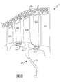
Figure 2 is an enlarged sectional view of a section of the gas turbine engine. -
Figure 1 schematically illustrates agas turbine engine 20. Thegas turbine engine 20 is disclosed herein as a two-spool turbofan that generally incorporates afan section 22, acompressor section 24, acombustor section 26 and aturbine section 28. Alternative engines might include an augmentor section (not shown) among other systems or features. Thefan section 22 drives air along a bypass flowpath while thecompressor section 24 drives air along a core flowpath for compression and communication into thecombustor section 26 then expansion through theturbine section 28. Although depicted as a turbofan gas turbine engine in the disclosed non-limiting embodiment, it should be understood that the concepts described herein are not limited to use with turbofans as the teachings may be applied to other types of turbine engines. - The
engine 20 generally includes alow speed spool 30 and ahigh speed spool 32 mounted for rotation about an engine central longitudinal axis A relative to an enginestatic structure 36 viaseveral bearing systems 38. It should be understood thatvarious bearing systems 38 at various locations may alternatively or additionally be provided. - The
low speed spool 30 generally includes aninner shaft 40 that interconnects afan 42, alow pressure compressor 44 and alow pressure turbine 46. Theinner shaft 40 is connected to thefan 42 through a gearedarchitecture 48 to drive thefan 42 at a lower speed than thelow speed spool 30. Thehigh speed spool 32 includes anouter shaft 50 that interconnects ahigh pressure compressor 52 andhigh pressure turbine 54. Acombustor 56 is arranged between thehigh pressure compressor 52 and thehigh pressure turbine 54. Theinner shaft 40 and theouter shaft 50 are concentric and rotate about the engine central longitudinal axis A which is collinear with their longitudinal axes. - The core airflow is compressed by the
low pressure compressor 44 then thehigh pressure compressor 52, mixed with fuel and burned in thecombustor 56, then expanded over thehigh pressure turbine 54 andlow pressure turbine 46. Theturbines low speed spool 30 andhigh speed spool 32 in response to the expansion. - With reference to
Figure 2 , thelow pressure turbine 46 generally includes acase 60 with a multiple of (at least two) low pressure turbine stages. In the disclosed non-limiting embodiment, thecase 60 is manufactured of a ceramic matrix composite (CMC) material or metal superalloy. It should be understood that examples of CMC material for all componentry discussed herein may include, but are not limited to, for example, S200 and SiC/SiC. It should be also understood that examples of metal superalloy for all componentry discussed herein may include, but are not limited to, for example, INCO 718 and Waspaloy. - A
rotor module 62 includes multiple rows ofCMC airfoils common CMC drum 66. The rows ofairfoils CMC vane structures - The
rotor module 62 further defines a radially inwardly extendingmount 70 which collectively mounts theLPT rotor module 62 to theinner rotor shaft 40 through a ring of fasteners or other such interface (Figure 1 ). The radially inwardly extendingmount 70 may extend generally from an axially central location of thecommon CMC drum 66adjacent airfoil row 64B. That is, therotor module 62 is a unitary component which integrates multiple rows ofairfoils common CMC drum 66 without the heretofor utilized fir tree attachments otherwise conventionally required for each blade. - The
rotor module 62 defines a single unitary CMC structure which may additionally receive separate, typically more geometrically complicated, features such asknife edge seals 72. Theknife edge seals 72 and other such features may be manufactured of a monolithic ceramic or metal alloy material different from the CMC material. Theknife edge seals 72 are bonded into therotor module 62 or otherwise mounted therein. - Hardware complexity and weight are significantly decreases with a
unitary rotor module 62. Therotor module 62 eliminates inter-stage fasteners along with any added material mass required to lower stresses in the fastener region. Therotor module 62 may require a splitlow pressure case 60 for assembly. That is, since therotor module 62 is an integral module, thecase 60 must be assembled around therotor module 62. Thecase 60 may be assembled from, for example, two longitudinal halves which are assembled together with a multiple of fasteners f. - It should be understood that like reference numerals identify corresponding or similar elements throughout the several drawings. It should also be understood that although a particular component arrangement is disclosed in the illustrated embodiment, other arrangements will benefit herefrom.
- Although particular step sequences are shown, described, and claimed, it should be understood that steps may be performed in any order, separated or combined unless otherwise indicated and will still benefit from the present disclosure.
- The foregoing description is exemplary rather than defined by the limitations within. Various non-limiting embodiments are disclosed herein, however, one of ordinary skill in the art would recognize that various modifications and variations in light of the above teachings will fall within the scope of the appended claims. It is therefore to be understood that within the scope of the appended claims, the disclosure may be practiced other than as specifically described. For that reason the appended claims should be studied to determine true scope and content.
Claims (15)
- A rotor module (62) for a gas turbine engine (20) comprising:a common CMC drum (66) defined about an axis (A); anda multiple of CMC airfoil rows (64A,64B,64C) which extend from said common CMC drum (66).
- The rotor module (62) as recited in claim 1, further comprising a split case (60) within which said rotor module (62) rotates.
- The rotor module (62) as recited in claim 1 or 2, further comprising a monolithic ceramic feature (72) mounted to said common CMC drum (66).
- The rotor module (62) as recited in claim 3, wherein said monolithic ceramic feature is a knife edge seal (72).
- The rotor module (62) as recited in claim 1 or 2, further comprising a metallic alloy feature (72) mounted to said common CMC drum (66).
- The rotor module (62) as recited in claim 5, wherein said metallic alloy feature is a knife edge seal (72).
- The rotor module (62) as recited in any preceding claim, wherein said multiple of CMC airfoil rows (64A,64B,64C) are within a compressor section (24) of the gas turbine engine (20).
- The rotor module (62) as recited in any preceding claim, wherein said multiple of CMC airfoil rows (64A,64B,64C) are within a high pressure compressor (52) section of the gas turbine engine (20).
- The rotor module as recited in any of claims 1 to 6, wherein said multiple of CMC airfoil rows are within a turbine section (28) of the gas turbine engine (20), optionally within a low pressure turbine section (46) of the gas turbine engine (20).
- A turbine assembly for a gas turbine engine (20) comprising:a split case (60) defined about an axis (A); anda turbine rotor module (62) having a multiple of CMC airfoil rows (64A,64B,64C) which extend from a common CMC drum (66) which rotates about said axis (A).
- The turbine assembly as recited in claim 10, further comprising a monolithic ceramic feature (72) or a metallic alloy feature (72) mounted to said common CMC drum (66).
- The turbine assembly as recited in claim 11, wherein said monolithic ceramic feature or said metallic alloy feature is a knife edge seal (72).
- The turbine assembly as recited in any of claims 10 to 12, wherein said turbine rotor module (62) is within a low pressure turbine section (46) of the gas turbine engine (20).
- A method of assembling a turbine assembly for a gas turbine engine (20) comprising:assembling a split case (60) around a common CMC drum (66) defined about an axis (A), a multiple of CMC airfoil rows (64A,64B,64C) extending from the common CMC drum (66).
- The method as recited in claim 14, further comprising assembling two longitudinal halves of the split case with a multiple of fasteners (f).
Applications Claiming Priority (1)
| Application Number | Priority Date | Filing Date | Title |
|---|---|---|---|
| US13/116,129 US20120301275A1 (en) | 2011-05-26 | 2011-05-26 | Integrated ceramic matrix composite rotor module for a gas turbine engine |
Publications (3)
| Publication Number | Publication Date |
|---|---|
| EP2570608A2 true EP2570608A2 (en) | 2013-03-20 |
| EP2570608A3 EP2570608A3 (en) | 2015-05-27 |
| EP2570608B1 EP2570608B1 (en) | 2018-07-04 |
Family
ID=46149269
Family Applications (1)
| Application Number | Title | Priority Date | Filing Date |
|---|---|---|---|
| EP12169252.9A Active EP2570608B1 (en) | 2011-05-26 | 2012-05-24 | Ceramic matrix composite rotor module for a gas turbine engine, corresponding turbine assembly and method of assembling |
Country Status (3)
| Country | Link |
|---|---|
| US (1) | US20120301275A1 (en) |
| EP (1) | EP2570608B1 (en) |
| JP (1) | JP5608701B2 (en) |
Families Citing this family (16)
| Publication number | Priority date | Publication date | Assignee | Title |
|---|---|---|---|---|
| US9631916B2 (en) * | 2013-03-13 | 2017-04-25 | Rolls Royce Corporation | Component including structures for determinant loading |
| CN107002690B (en) * | 2014-10-15 | 2021-03-02 | 赛峰航空器发动机 | Rotating assembly for a turbine engine including a self-supporting rotor casing |
| US10648481B2 (en) * | 2014-11-17 | 2020-05-12 | United Technologies Corporation | Fiber reinforced spacer for a gas turbine engine |
| US9938840B2 (en) * | 2015-02-10 | 2018-04-10 | United Technologies Corporation | Stator vane with platform having sloped face |
| US10161250B2 (en) * | 2015-02-10 | 2018-12-25 | United Technologies Corporation | Rotor with axial arm having protruding ramp |
| US20170030212A1 (en) * | 2015-07-29 | 2017-02-02 | General Electric Company | Near flow path seal for a turbomachine |
| US10590786B2 (en) | 2016-05-03 | 2020-03-17 | General Electric Company | System and method for cooling components of a gas turbine engine |
| KR101914870B1 (en) | 2017-06-28 | 2018-12-28 | 두산중공업 주식회사 | Method of disassembling and assembling a gas turbine and a gas turbine assembled thereby |
| US10724380B2 (en) | 2017-08-07 | 2020-07-28 | General Electric Company | CMC blade with internal support |
| US10774668B2 (en) * | 2017-09-20 | 2020-09-15 | General Electric Company | Intersage seal assembly for counter rotating turbine |
| GB201813086D0 (en) | 2018-08-10 | 2018-09-26 | Rolls Royce Plc | Efficient gas turbine engine |
| GB201813081D0 (en) | 2018-08-10 | 2018-09-26 | Rolls Royce Plc | Efficient gas turbine engine |
| GB201813082D0 (en) | 2018-08-10 | 2018-09-26 | Rolls Royce Plc | Efficient gas turbine engine |
| GB201813079D0 (en) | 2018-08-10 | 2018-09-26 | Rolls Royce Plc | Effcient gas turbine engine |
| DE102020209579A1 (en) | 2020-07-29 | 2022-02-03 | MTU Aero Engines AG | HIGH PRESSURE COMPRESSOR SECTION FOR A CYCLE MACHINE AND RELATIVE CYCLE MACHINE, AND METHOD FOR MANUFACTURING A COMPONENT FOR THE HIGH PRESSURE COMPRESSOR SECTION FROM A FIBER COMPOSITE |
| US11428160B2 (en) | 2020-12-31 | 2022-08-30 | General Electric Company | Gas turbine engine with interdigitated turbine and gear assembly |
Family Cites Families (26)
| Publication number | Priority date | Publication date | Assignee | Title |
|---|---|---|---|---|
| US4329114A (en) * | 1979-07-25 | 1982-05-11 | The United States Of America As Represented By The Administrator Of The National Aeronautics And Space Administration | Active clearance control system for a turbomachine |
| JP2598927Y2 (en) * | 1992-11-09 | 1999-08-23 | 東芝エンジニアリング株式会社 | Shaft sealing device |
| JPH07139305A (en) * | 1993-11-16 | 1995-05-30 | Mitsubishi Heavy Ind Ltd | Structure for labyrinth seal fixation |
| JPH09125907A (en) * | 1995-11-06 | 1997-05-13 | Ishikawajima Harima Heavy Ind Co Ltd | Turbine blade shroud structure |
| US5932356A (en) * | 1996-03-21 | 1999-08-03 | United Technologies Corporation | Abrasive/abradable gas path seal system |
| US6203273B1 (en) * | 1998-12-22 | 2001-03-20 | United Technologies Corporation | Rotary machine |
| US6213720B1 (en) * | 1999-06-11 | 2001-04-10 | Alliedsignal, Inc. | High strength composite reinforced turbomachinery disk |
| JP2001123803A (en) * | 1999-10-21 | 2001-05-08 | Toshiba Corp | Seal device, steam turbine and power plant equipped with the same |
| JP2002061502A (en) * | 2000-08-17 | 2002-02-28 | Senshin Zairyo Riyo Gas Generator Kenkyusho:Kk | Disc or brisk formed of ceramics composite material |
| US20020108376A1 (en) * | 2001-02-14 | 2002-08-15 | Stevens Eloy C. | Thermal management system for turbomachinery |
| FR2825748B1 (en) * | 2001-06-07 | 2003-11-07 | Snecma Moteurs | TURBOMACHINE ROTOR ARRANGEMENT WITH TWO BLADE DISCS SEPARATED BY A SPACER |
| US6554563B2 (en) * | 2001-08-13 | 2003-04-29 | General Electric Company | Tangential flow baffle |
| JP4016648B2 (en) * | 2001-12-07 | 2007-12-05 | 株式会社Ihi | Blisk |
| US6619030B1 (en) * | 2002-03-01 | 2003-09-16 | General Electric Company | Aircraft engine with inter-turbine engine frame supported counter rotating low pressure turbine rotors |
| US6709230B2 (en) * | 2002-05-31 | 2004-03-23 | Siemens Westinghouse Power Corporation | Ceramic matrix composite gas turbine vane |
| US9068464B2 (en) * | 2002-09-17 | 2015-06-30 | Siemens Energy, Inc. | Method of joining ceramic parts and articles so formed |
| US7128535B2 (en) * | 2003-11-26 | 2006-10-31 | United Technologies Corporation | Turbine drum rotor for a turbine engine |
| US7059831B2 (en) * | 2004-04-15 | 2006-06-13 | United Technologies Corporation | Turbine engine disk spacers |
| JP2007016704A (en) * | 2005-07-08 | 2007-01-25 | Mitsubishi Heavy Ind Ltd | Seal structure of rotating shaft and rotary machine having the same |
| JP4182098B2 (en) * | 2005-11-28 | 2008-11-19 | 川崎重工業株式会社 | Gas turbine casing |
| US7470113B2 (en) * | 2006-06-22 | 2008-12-30 | United Technologies Corporation | Split knife edge seals |
| US7758311B2 (en) * | 2006-10-12 | 2010-07-20 | General Electric Company | Part span shrouded fan blisk |
| JP2008144617A (en) * | 2006-12-07 | 2008-06-26 | Mitsubishi Heavy Ind Ltd | Gas turbine casing structure |
| US20080148708A1 (en) * | 2006-12-20 | 2008-06-26 | General Electric Company | Turbine engine system with shafts for improved weight and vibration characteristic |
| US20110027557A1 (en) * | 2009-07-31 | 2011-02-03 | Glen Harold Kirby | Solvent based environmental barrier coatings for high temperature ceramic components |
| US8303245B2 (en) * | 2009-10-09 | 2012-11-06 | General Electric Company | Shroud assembly with discourager |
-
2011
- 2011-05-26 US US13/116,129 patent/US20120301275A1/en not_active Abandoned
-
2012
- 2012-04-27 JP JP2012101927A patent/JP5608701B2/en active Active
- 2012-05-24 EP EP12169252.9A patent/EP2570608B1/en active Active
Non-Patent Citations (1)
| Title |
|---|
| None |
Also Published As
| Publication number | Publication date |
|---|---|
| US20120301275A1 (en) | 2012-11-29 |
| EP2570608B1 (en) | 2018-07-04 |
| EP2570608A3 (en) | 2015-05-27 |
| JP2012246918A (en) | 2012-12-13 |
| JP5608701B2 (en) | 2014-10-15 |
Similar Documents
| Publication | Publication Date | Title |
|---|---|---|
| EP2570608B1 (en) | Ceramic matrix composite rotor module for a gas turbine engine, corresponding turbine assembly and method of assembling | |
| EP2570593B1 (en) | Ceramic matrix composite airfoil segment for a gas turbine engine, corresponding structure and method of assembling | |
| US8905711B2 (en) | Ceramic matrix composite vane structures for a gas turbine engine turbine | |
| EP3640434B1 (en) | Hybrid rotor disk assembly with ceramic matrix composites platform for a gas turbine engine | |
| EP2570602B1 (en) | Ceramic matrix composite vane structure for a gas turbine engine, corresponding low pressure turbine and assembling method | |
| EP2570609B1 (en) | Ceramic matrix composite component and corresponding rotor disk assembly | |
| EP2570607B1 (en) | Gas turbine engine with ceramic matrix composite static structure and rotor module, and corresponding method of tip clearance control | |
| EP2570601B1 (en) | Ceramic matrix composite rotor disk for a gas turbine engine and corresponding rotor module | |
| US9011085B2 (en) | Ceramic matrix composite continuous “I”-shaped fiber geometry airfoil for a gas turbine engine | |
| EP2570598B1 (en) | Rotor disk assembly for a gas turbine engine | |
| US10184402B2 (en) | Ceramic matrix composite turbine exhaust case for a gas turbine engine | |
| EP2570605B1 (en) | Ceramic matrix composite rotor disk for a gas turbine engine and corresponding rotor module | |
| US20150377073A1 (en) | Titanium aluminide turbine exhaust structure |
Legal Events
| Date | Code | Title | Description |
|---|---|---|---|
| PUAI | Public reference made under article 153(3) epc to a published international application that has entered the european phase |
Free format text: ORIGINAL CODE: 0009012 |
|
| AK | Designated contracting states |
Kind code of ref document: A2 Designated state(s): AL AT BE BG CH CY CZ DE DK EE ES FI FR GB GR HR HU IE IS IT LI LT LU LV MC MK MT NL NO PL PT RO RS SE SI SK SM TR |
|
| AX | Request for extension of the european patent |
Extension state: BA ME |
|
| PUAL | Search report despatched |
Free format text: ORIGINAL CODE: 0009013 |
|
| AK | Designated contracting states |
Kind code of ref document: A3 Designated state(s): AL AT BE BG CH CY CZ DE DK EE ES FI FR GB GR HR HU IE IS IT LI LT LU LV MC MK MT NL NO PL PT RO RS SE SI SK SM TR |
|
| AX | Request for extension of the european patent |
Extension state: BA ME |
|
| RIC1 | Information provided on ipc code assigned before grant |
Ipc: F01D 5/34 20060101ALI20150420BHEP Ipc: C04B 35/80 20060101ALI20150420BHEP Ipc: F01D 5/28 20060101AFI20150420BHEP Ipc: F01D 11/00 20060101ALI20150420BHEP |
|
| 17P | Request for examination filed |
Effective date: 20151127 |
|
| RBV | Designated contracting states (corrected) |
Designated state(s): AL AT BE BG CH CY CZ DE DK EE ES FI FR GB GR HR HU IE IS IT LI LT LU LV MC MK MT NL NO PL PT RO RS SE SI SK SM TR |
|
| RAP1 | Party data changed (applicant data changed or rights of an application transferred) |
Owner name: UNITED TECHNOLOGIES CORPORATION |
|
| 17Q | First examination report despatched |
Effective date: 20161017 |
|
| STAA | Information on the status of an ep patent application or granted ep patent |
Free format text: STATUS: EXAMINATION IS IN PROGRESS |
|
| GRAP | Despatch of communication of intention to grant a patent |
Free format text: ORIGINAL CODE: EPIDOSNIGR1 |
|
| STAA | Information on the status of an ep patent application or granted ep patent |
Free format text: STATUS: GRANT OF PATENT IS INTENDED |
|
| RIC1 | Information provided on ipc code assigned before grant |
Ipc: F01D 11/00 20060101ALI20171121BHEP Ipc: C04B 35/80 20060101ALI20171121BHEP Ipc: F01D 5/28 20060101AFI20171121BHEP Ipc: C04B 37/00 20060101ALI20171121BHEP Ipc: F01D 5/34 20060101ALI20171121BHEP |
|
| INTG | Intention to grant announced |
Effective date: 20171213 |
|
| GRAS | Grant fee paid |
Free format text: ORIGINAL CODE: EPIDOSNIGR3 |
|
| AK | Designated contracting states |
Kind code of ref document: B1 Designated state(s): AL AT BE BG CH CY CZ DE DK EE ES FI FR GB GR HR HU IE IS IT LI LT LU LV MC MK MT NL NO PL PT RO RS SE SI SK SM TR |
|
| REG | Reference to a national code |
Ref country code: GB Ref legal event code: FG4D |
|
| GRAA | (expected) grant |
Free format text: ORIGINAL CODE: 0009210 |
|
| STAA | Information on the status of an ep patent application or granted ep patent |
Free format text: STATUS: THE PATENT HAS BEEN GRANTED |
|
| REG | Reference to a national code |
Ref country code: CH Ref legal event code: EP |
|
| REG | Reference to a national code |
Ref country code: AT Ref legal event code: REF Ref document number: 1014725 Country of ref document: AT Kind code of ref document: T Effective date: 20180715 |
|
| REG | Reference to a national code |
Ref country code: IE Ref legal event code: FG4D |
|
| REG | Reference to a national code |
Ref country code: DE Ref legal event code: R096 Ref document number: 602012047998 Country of ref document: DE |
|
| REG | Reference to a national code |
Ref country code: NL Ref legal event code: MP Effective date: 20180704 |
|
| REG | Reference to a national code |
Ref country code: LT Ref legal event code: MG4D |
|
| REG | Reference to a national code |
Ref country code: AT Ref legal event code: MK05 Ref document number: 1014725 Country of ref document: AT Kind code of ref document: T Effective date: 20180704 |
|
| PG25 | Lapsed in a contracting state [announced via postgrant information from national office to epo] |
Ref country code: NL Free format text: LAPSE BECAUSE OF FAILURE TO SUBMIT A TRANSLATION OF THE DESCRIPTION OR TO PAY THE FEE WITHIN THE PRESCRIBED TIME-LIMIT Effective date: 20180704 |
|
| PG25 | Lapsed in a contracting state [announced via postgrant information from national office to epo] |
Ref country code: LT Free format text: LAPSE BECAUSE OF FAILURE TO SUBMIT A TRANSLATION OF THE DESCRIPTION OR TO PAY THE FEE WITHIN THE PRESCRIBED TIME-LIMIT Effective date: 20180704 Ref country code: RS Free format text: LAPSE BECAUSE OF FAILURE TO SUBMIT A TRANSLATION OF THE DESCRIPTION OR TO PAY THE FEE WITHIN THE PRESCRIBED TIME-LIMIT Effective date: 20180704 Ref country code: FI Free format text: LAPSE BECAUSE OF FAILURE TO SUBMIT A TRANSLATION OF THE DESCRIPTION OR TO PAY THE FEE WITHIN THE PRESCRIBED TIME-LIMIT Effective date: 20180704 Ref country code: SE Free format text: LAPSE BECAUSE OF FAILURE TO SUBMIT A TRANSLATION OF THE DESCRIPTION OR TO PAY THE FEE WITHIN THE PRESCRIBED TIME-LIMIT Effective date: 20180704 Ref country code: PL Free format text: LAPSE BECAUSE OF FAILURE TO SUBMIT A TRANSLATION OF THE DESCRIPTION OR TO PAY THE FEE WITHIN THE PRESCRIBED TIME-LIMIT Effective date: 20180704 Ref country code: CZ Free format text: LAPSE BECAUSE OF FAILURE TO SUBMIT A TRANSLATION OF THE DESCRIPTION OR TO PAY THE FEE WITHIN THE PRESCRIBED TIME-LIMIT Effective date: 20180704 Ref country code: BG Free format text: LAPSE BECAUSE OF FAILURE TO SUBMIT A TRANSLATION OF THE DESCRIPTION OR TO PAY THE FEE WITHIN THE PRESCRIBED TIME-LIMIT Effective date: 20181004 Ref country code: NO Free format text: LAPSE BECAUSE OF FAILURE TO SUBMIT A TRANSLATION OF THE DESCRIPTION OR TO PAY THE FEE WITHIN THE PRESCRIBED TIME-LIMIT Effective date: 20181004 Ref country code: GR Free format text: LAPSE BECAUSE OF FAILURE TO SUBMIT A TRANSLATION OF THE DESCRIPTION OR TO PAY THE FEE WITHIN THE PRESCRIBED TIME-LIMIT Effective date: 20181005 Ref country code: AT Free format text: LAPSE BECAUSE OF FAILURE TO SUBMIT A TRANSLATION OF THE DESCRIPTION OR TO PAY THE FEE WITHIN THE PRESCRIBED TIME-LIMIT Effective date: 20180704 Ref country code: IS Free format text: LAPSE BECAUSE OF FAILURE TO SUBMIT A TRANSLATION OF THE DESCRIPTION OR TO PAY THE FEE WITHIN THE PRESCRIBED TIME-LIMIT Effective date: 20181104 |
|
| PG25 | Lapsed in a contracting state [announced via postgrant information from national office to epo] |
Ref country code: HR Free format text: LAPSE BECAUSE OF FAILURE TO SUBMIT A TRANSLATION OF THE DESCRIPTION OR TO PAY THE FEE WITHIN THE PRESCRIBED TIME-LIMIT Effective date: 20180704 Ref country code: ES Free format text: LAPSE BECAUSE OF FAILURE TO SUBMIT A TRANSLATION OF THE DESCRIPTION OR TO PAY THE FEE WITHIN THE PRESCRIBED TIME-LIMIT Effective date: 20180704 Ref country code: LV Free format text: LAPSE BECAUSE OF FAILURE TO SUBMIT A TRANSLATION OF THE DESCRIPTION OR TO PAY THE FEE WITHIN THE PRESCRIBED TIME-LIMIT Effective date: 20180704 Ref country code: AL Free format text: LAPSE BECAUSE OF FAILURE TO SUBMIT A TRANSLATION OF THE DESCRIPTION OR TO PAY THE FEE WITHIN THE PRESCRIBED TIME-LIMIT Effective date: 20180704 |
|
| REG | Reference to a national code |
Ref country code: DE Ref legal event code: R097 Ref document number: 602012047998 Country of ref document: DE |
|
| PG25 | Lapsed in a contracting state [announced via postgrant information from national office to epo] |
Ref country code: IT Free format text: LAPSE BECAUSE OF FAILURE TO SUBMIT A TRANSLATION OF THE DESCRIPTION OR TO PAY THE FEE WITHIN THE PRESCRIBED TIME-LIMIT Effective date: 20180704 Ref country code: RO Free format text: LAPSE BECAUSE OF FAILURE TO SUBMIT A TRANSLATION OF THE DESCRIPTION OR TO PAY THE FEE WITHIN THE PRESCRIBED TIME-LIMIT Effective date: 20180704 Ref country code: EE Free format text: LAPSE BECAUSE OF FAILURE TO SUBMIT A TRANSLATION OF THE DESCRIPTION OR TO PAY THE FEE WITHIN THE PRESCRIBED TIME-LIMIT Effective date: 20180704 |
|
| PLBE | No opposition filed within time limit |
Free format text: ORIGINAL CODE: 0009261 |
|
| STAA | Information on the status of an ep patent application or granted ep patent |
Free format text: STATUS: NO OPPOSITION FILED WITHIN TIME LIMIT |
|
| PG25 | Lapsed in a contracting state [announced via postgrant information from national office to epo] |
Ref country code: SK Free format text: LAPSE BECAUSE OF FAILURE TO SUBMIT A TRANSLATION OF THE DESCRIPTION OR TO PAY THE FEE WITHIN THE PRESCRIBED TIME-LIMIT Effective date: 20180704 Ref country code: DK Free format text: LAPSE BECAUSE OF FAILURE TO SUBMIT A TRANSLATION OF THE DESCRIPTION OR TO PAY THE FEE WITHIN THE PRESCRIBED TIME-LIMIT Effective date: 20180704 Ref country code: SM Free format text: LAPSE BECAUSE OF FAILURE TO SUBMIT A TRANSLATION OF THE DESCRIPTION OR TO PAY THE FEE WITHIN THE PRESCRIBED TIME-LIMIT Effective date: 20180704 |
|
| 26N | No opposition filed |
Effective date: 20190405 |
|
| PG25 | Lapsed in a contracting state [announced via postgrant information from national office to epo] |
Ref country code: SI Free format text: LAPSE BECAUSE OF FAILURE TO SUBMIT A TRANSLATION OF THE DESCRIPTION OR TO PAY THE FEE WITHIN THE PRESCRIBED TIME-LIMIT Effective date: 20180704 |
|
| REG | Reference to a national code |
Ref country code: CH Ref legal event code: PL |
|
| PG25 | Lapsed in a contracting state [announced via postgrant information from national office to epo] |
Ref country code: LI Free format text: LAPSE BECAUSE OF NON-PAYMENT OF DUE FEES Effective date: 20190531 Ref country code: CH Free format text: LAPSE BECAUSE OF NON-PAYMENT OF DUE FEES Effective date: 20190531 Ref country code: MC Free format text: LAPSE BECAUSE OF FAILURE TO SUBMIT A TRANSLATION OF THE DESCRIPTION OR TO PAY THE FEE WITHIN THE PRESCRIBED TIME-LIMIT Effective date: 20180704 |
|
| REG | Reference to a national code |
Ref country code: BE Ref legal event code: MM Effective date: 20190531 |
|
| PG25 | Lapsed in a contracting state [announced via postgrant information from national office to epo] |
Ref country code: LU Free format text: LAPSE BECAUSE OF NON-PAYMENT OF DUE FEES Effective date: 20190524 |
|
| PG25 | Lapsed in a contracting state [announced via postgrant information from national office to epo] |
Ref country code: TR Free format text: LAPSE BECAUSE OF FAILURE TO SUBMIT A TRANSLATION OF THE DESCRIPTION OR TO PAY THE FEE WITHIN THE PRESCRIBED TIME-LIMIT Effective date: 20180704 |
|
| PG25 | Lapsed in a contracting state [announced via postgrant information from national office to epo] |
Ref country code: IE Free format text: LAPSE BECAUSE OF NON-PAYMENT OF DUE FEES Effective date: 20190524 |
|
| PG25 | Lapsed in a contracting state [announced via postgrant information from national office to epo] |
Ref country code: BE Free format text: LAPSE BECAUSE OF NON-PAYMENT OF DUE FEES Effective date: 20190531 |
|
| PG25 | Lapsed in a contracting state [announced via postgrant information from national office to epo] |
Ref country code: FR Free format text: LAPSE BECAUSE OF NON-PAYMENT OF DUE FEES Effective date: 20190531 Ref country code: PT Free format text: LAPSE BECAUSE OF FAILURE TO SUBMIT A TRANSLATION OF THE DESCRIPTION OR TO PAY THE FEE WITHIN THE PRESCRIBED TIME-LIMIT Effective date: 20181105 |
|
| PG25 | Lapsed in a contracting state [announced via postgrant information from national office to epo] |
Ref country code: CY Free format text: LAPSE BECAUSE OF FAILURE TO SUBMIT A TRANSLATION OF THE DESCRIPTION OR TO PAY THE FEE WITHIN THE PRESCRIBED TIME-LIMIT Effective date: 20180704 |
|
| PG25 | Lapsed in a contracting state [announced via postgrant information from national office to epo] |
Ref country code: HU Free format text: LAPSE BECAUSE OF FAILURE TO SUBMIT A TRANSLATION OF THE DESCRIPTION OR TO PAY THE FEE WITHIN THE PRESCRIBED TIME-LIMIT; INVALID AB INITIO Effective date: 20120524 Ref country code: MT Free format text: LAPSE BECAUSE OF FAILURE TO SUBMIT A TRANSLATION OF THE DESCRIPTION OR TO PAY THE FEE WITHIN THE PRESCRIBED TIME-LIMIT Effective date: 20180704 |
|
| PG25 | Lapsed in a contracting state [announced via postgrant information from national office to epo] |
Ref country code: MK Free format text: LAPSE BECAUSE OF FAILURE TO SUBMIT A TRANSLATION OF THE DESCRIPTION OR TO PAY THE FEE WITHIN THE PRESCRIBED TIME-LIMIT Effective date: 20180704 |
|
| REG | Reference to a national code |
Ref country code: DE Ref legal event code: R081 Ref document number: 602012047998 Country of ref document: DE Owner name: RAYTHEON TECHNOLOGIES CORPORATION (N.D.GES.D.S, US Free format text: FORMER OWNER: UNITED TECHNOLOGIES CORPORATION, FARMINGTON, CONN., US Ref country code: DE Ref legal event code: R081 Ref document number: 602012047998 Country of ref document: DE Owner name: RTX CORPORATION (N.D.GES.D. STAATES DELAWARE),, US Free format text: FORMER OWNER: UNITED TECHNOLOGIES CORPORATION, FARMINGTON, CONN., US |
|
| P01 | Opt-out of the competence of the unified patent court (upc) registered |
Effective date: 20230520 |
|
| PGFP | Annual fee paid to national office [announced via postgrant information from national office to epo] |
Ref country code: DE Payment date: 20250423 Year of fee payment: 14 |
|
| PGFP | Annual fee paid to national office [announced via postgrant information from national office to epo] |
Ref country code: GB Payment date: 20250423 Year of fee payment: 14 |
|
| REG | Reference to a national code |
Ref country code: DE Ref legal event code: R081 Ref document number: 602012047998 Country of ref document: DE Owner name: RTX CORPORATION (N.D.GES.D. STAATES DELAWARE),, US Free format text: FORMER OWNER: RAYTHEON TECHNOLOGIES CORPORATION (N.D.GES.D.STAATES DELAWARE), ARLINGTON, VA, US |