EP2570605A2 - Ceramic matrix composite rotor disk for a gas turbine engine and corresponding rotor module - Google Patents
Ceramic matrix composite rotor disk for a gas turbine engine and corresponding rotor module Download PDFInfo
- Publication number
- EP2570605A2 EP2570605A2 EP20120169231 EP12169231A EP2570605A2 EP 2570605 A2 EP2570605 A2 EP 2570605A2 EP 20120169231 EP20120169231 EP 20120169231 EP 12169231 A EP12169231 A EP 12169231A EP 2570605 A2 EP2570605 A2 EP 2570605A2
- Authority
- EP
- European Patent Office
- Prior art keywords
- cmc
- disk
- rail
- hub
- defines
- Prior art date
- Legal status (The legal status is an assumption and is not a legal conclusion. Google has not performed a legal analysis and makes no representation as to the accuracy of the status listed.)
- Granted
Links
Images


Classifications
-
- F—MECHANICAL ENGINEERING; LIGHTING; HEATING; WEAPONS; BLASTING
- F01—MACHINES OR ENGINES IN GENERAL; ENGINE PLANTS IN GENERAL; STEAM ENGINES
- F01D—NON-POSITIVE DISPLACEMENT MACHINES OR ENGINES, e.g. STEAM TURBINES
- F01D5/00—Blades; Blade-carrying members; Heating, heat-insulating, cooling or antivibration means on the blades or the members
- F01D5/12—Blades
- F01D5/28—Selecting particular materials; Particular measures relating thereto; Measures against erosion or corrosion
- F01D5/282—Selecting composite materials, e.g. blades with reinforcing filaments
-
- F—MECHANICAL ENGINEERING; LIGHTING; HEATING; WEAPONS; BLASTING
- F01—MACHINES OR ENGINES IN GENERAL; ENGINE PLANTS IN GENERAL; STEAM ENGINES
- F01D—NON-POSITIVE DISPLACEMENT MACHINES OR ENGINES, e.g. STEAM TURBINES
- F01D5/00—Blades; Blade-carrying members; Heating, heat-insulating, cooling or antivibration means on the blades or the members
- F01D5/02—Blade-carrying members, e.g. rotors
- F01D5/026—Shaft to shaft connections
-
- F—MECHANICAL ENGINEERING; LIGHTING; HEATING; WEAPONS; BLASTING
- F01—MACHINES OR ENGINES IN GENERAL; ENGINE PLANTS IN GENERAL; STEAM ENGINES
- F01D—NON-POSITIVE DISPLACEMENT MACHINES OR ENGINES, e.g. STEAM TURBINES
- F01D5/00—Blades; Blade-carrying members; Heating, heat-insulating, cooling or antivibration means on the blades or the members
- F01D5/02—Blade-carrying members, e.g. rotors
- F01D5/06—Rotors for more than one axial stage, e.g. of drum or multiple disc type; Details thereof, e.g. shafts, shaft connections
- F01D5/066—Connecting means for joining rotor-discs or rotor-elements together, e.g. by a central bolt, by clamps
-
- F—MECHANICAL ENGINEERING; LIGHTING; HEATING; WEAPONS; BLASTING
- F01—MACHINES OR ENGINES IN GENERAL; ENGINE PLANTS IN GENERAL; STEAM ENGINES
- F01D—NON-POSITIVE DISPLACEMENT MACHINES OR ENGINES, e.g. STEAM TURBINES
- F01D5/00—Blades; Blade-carrying members; Heating, heat-insulating, cooling or antivibration means on the blades or the members
- F01D5/12—Blades
- F01D5/28—Selecting particular materials; Particular measures relating thereto; Measures against erosion or corrosion
- F01D5/284—Selection of ceramic materials
-
- F—MECHANICAL ENGINEERING; LIGHTING; HEATING; WEAPONS; BLASTING
- F01—MACHINES OR ENGINES IN GENERAL; ENGINE PLANTS IN GENERAL; STEAM ENGINES
- F01D—NON-POSITIVE DISPLACEMENT MACHINES OR ENGINES, e.g. STEAM TURBINES
- F01D5/00—Blades; Blade-carrying members; Heating, heat-insulating, cooling or antivibration means on the blades or the members
- F01D5/34—Rotor-blade aggregates of unitary construction, e.g. formed of sheet laminae
-
- F—MECHANICAL ENGINEERING; LIGHTING; HEATING; WEAPONS; BLASTING
- F05—INDEXING SCHEMES RELATING TO ENGINES OR PUMPS IN VARIOUS SUBCLASSES OF CLASSES F01-F04
- F05D—INDEXING SCHEME FOR ASPECTS RELATING TO NON-POSITIVE-DISPLACEMENT MACHINES OR ENGINES, GAS-TURBINES OR JET-PROPULSION PLANTS
- F05D2300/00—Materials; Properties thereof
- F05D2300/60—Properties or characteristics given to material by treatment or manufacturing
- F05D2300/603—Composites; e.g. fibre-reinforced
- F05D2300/6033—Ceramic matrix composites [CMC]
Definitions
- the present disclosure relates to a gas turbine engine, and more particularly to Ceramic Matrix Composites (CMC) rotor disk components therefor.
- CMC Ceramic Matrix Composites
- Turbine rotor assemblies often include a multiple of rotor disks that may be fastened together by bolts, tie rods and other structures.
- Each of the rotor disks includes a multiple of shrouded blades which are typically retained through a firtree slot arrangement within a rim of the rotor disk.
- the innermost diameter of the rotor disk defines a bore that provides self-retention capabilities through the minimization of excessive hoop growth that would otherwise occur without this feature.
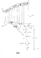
- the conventional bore geometrically includes a thin midsection that extends radially inward from the rim and flares out at an innermost diameter ( Figure 3 ). This geometry may not lend itself to Ceramic matrix composites (CMC).
- a disk for a gas turbine engine includes a CMC hub and a rail integrated with the CMC hub opposite a multiple of CMC airfoils, the rail defines a rail platform section that tapers to a rail inner bore.
- a CMC disk for a gas turbine engine includes a multiple of airfoils which extend from a CMC hub and a rail integrated with said CMC hub opposite said multiple of airfoils, the rail defines a rail platform section adjacent to the multiple of airfoils that tapers to a rail inner bore.
- a rotor module for a gas turbine engine includes a first CMC disk with a first CMC hub, a first CMC arm extends from the CMC hub, the first CMC disk defined about an axis.
- a second CMC disk with a second CMC hub, a second CMC arm extends from the second CMC hub, the second CMC disk defined about an axis.
- a third CMC disk with a third CMC hub, the third CMC hub defines a bore about the axis, the first CMC arm and the second CMC arm fastened to the third CMC hub.
- FIG. 1 schematically illustrates a gas turbine engine 20.
- the gas turbine engine 20 is disclosed herein as a two-spool turbofan that generally incorporates a fan section 22, a compressor section 24, a combustor section 26 and a turbine section 28.
- Alternative engines might include an augmentor section (not shown) among other systems or features.
- the fan section 22 drives air along a bypass flowpath while the compressor section 24 drives air along a core flowpath for compression and communication into the combustor section 26 then expansion through the turbine section 28.
- FIG. 1 schematically illustrates a gas turbine engine 20.
- the gas turbine engine 20 is disclosed herein as a two-spool turbofan that generally incorporates a fan section 22, a compressor section 24, a combustor section 26 and a turbine section 28.
- Alternative engines might include an augmentor section (not shown) among other systems or features.
- the fan section 22 drives air along a bypass flowpath while the compressor section 24 drives air along a core flowpath for compression and communication into the combustor section 26
- the engine 20 generally includes a low speed spool 30 and a high speed spool 32 mounted for rotation about an engine central longitudinal axis A relative to an engine static structure 36 via several bearing systems 38. It should be understood that various bearing systems 38 at various locations may alternatively or additionally be provided.
- the low speed spool 30 generally includes an inner shaft 40 that interconnects a fan 42, a low pressure compressor 44 and a low pressure turbine 46.
- the inner shaft 40 is connected to the fan 42 through a geared architecture 48 to drive the fan 42 at a lower speed than the low speed spool 30.
- the high speed spool 32 includes an outer shaft 50 that interconnects a high pressure compressor 52 and high pressure turbine 54.
- a combustor 56 is arranged between the high pressure compressor 52 and the high pressure turbine 54.
- the inner shaft 40 and the outer shaft 50 are concentric and rotate about the engine central longitudinal axis A which is collinear with their longitudinal axes.
- the core airflow is compressed by the low pressure compressor 44 then the high pressure compressor 52, mixed and burned with fuel in the combustor 56, then expanded over the high pressure turbine 54 and low pressure turbine 46.
- the turbines 54, 46 rotationally drive the respective low speed spool 30 and high speed spool 32 in response to the expansion.
- the low pressure turbine 46 generally includes a low pressure turbine case 60 with a multiple of low pressure turbine stages.
- the low pressure turbine case 60 is manufactured of a ceramic matrix composite (CMC) material or metal super alloy.
- CMC material for all componentry discussed herein may include, but are not limited to, for example, S200 and SiC/SiC.
- metal superalloy for all componentry discussed herein may include, but are not limited to, for example, INCO 718 and Waspaloy.
- low pressure turbine Although depicted as a low pressure turbine in the disclosed embodiment, it should be understood that the concepts described herein are not limited to use with low pressure turbine as the teachings may be applied to other sections such as high pressure turbine, high pressure compressor, low pressure compressor and intermediate pressure turbine and intermediate pressure turbine of a three-spool architecture gas turbine engine.
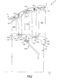
- a rotor module 62 includes a multiple (three shown) of CMC disks 64A, 64B, 64C.
- Each of the CMC disks 64A, 64B, 64C include a row of airfoils 66A, 66B, 66C which extend from a respective hub 68A, 68B, 68C.
- the rows of airfoils 66A, 66B, 66C are interspersed with CMC vane structures 70A, 70B to form a respective number of LPT stages. It should be understood that any number of stages may be provided.
- the disk may further include a ring-strut ring construction.
- the CMC disks 64A, 64C include arms 72A, 72C which extend from the respective hub 68A, 68C.
- the arms 72A, 72C are located a radial distance from the engine axis A generally equal to the self sustaining radius.
- the self sustaining radius is defined herein as the radius where the radial growth of the disk equals the radial growth of a free spinning ring.
- Mass radially inboard of the self sustaining radius is load carrying and mass radially outboard of the self-sustaining radius is not load carrying and can not support itself.
- Disk material outboard of the self-sustaining radius may generally increase bore stress and material inboard of the self-sustaining radius may generally reduce bore stress.
- the arms 72A, 72C trap a mount 74B which extends from hub 68B.
- a multiple of fasteners 76 (only one shown) mount the arms 72A, 72C to the mount 74B to assemble the CMC disks 64A, 64B, 64C and form the LPT rotor module 62.
- the radially inwardly extending mount 74B collectively mounts the LPT rotor module 62 to the inner rotor shaft 40 ( Figure 1 ).
- the arms 72A, 72C typically include knife edge seals 71 which interface with the CMC vane structures 70A, 70B.
- Each of the CMC disks 64A, 64B, 64C utilize the CMC hoop strength characteristics of an integrated bladed rotor with a full hoop shroud to form a ring-strut-ring structure.
- the term "full hoop" is defined herein as an uninterrupted member such that the airfoils do not pass through apertures formed therethrough.
- An outer shroud 78A, 78B, 78C of each of the CMC disks 64A, 64B, 64C forms the full hoop ring structure at an outermost tip of each respective row of airfoils 66A, 66B, 66C which is integrated therewith with large generous fillets to allow the fibers to uniformly transfer load.
- the root portion of the airfoils are also integrated into the full hoop disk with generous fillets to allow for the fibers to again better transfer load through the structure to the respective hub 68A, 68B, 68C. It should be understood that various CMC manufacturing and ply structures may be utilized.
- Each hub 68A, 68C defines a rail 80A, 80C which defines the innermost bore radius B relative to the engine axis A.
- the innermost bore radius B of each of the CMC disks 64A, 64B, 64C is significantly greater than a conventional rim, disk, bore, teardrop-like structure in cross section ( Figure 3 ; RELATED ART). That is, the innermost bore radius B of each rail 80A, 80C defines a relatively large bore diameter which reduces overall disk weight.
- the term "rail” as utilized herein is the annular structure inboard of the row of airfoils 66A, 66B, 66C which essentially replace the conventional rim, disk, bore, teardrop-like structure.
- the rail geometry readily lends itself to CMC material and preserves continuity of the internal stress carrying fibers.
- the rail design further facilitates the balance of hoop stresses by minimization of free ring growth and minimizes moments which cause rolling that may otherwise increase stresses.
- the rail inner bore 82 defines a radial dimension of 1.1X - 1.6X as compared to an inner bore diameter 1xC of the conventional rim, disk, bore teardrop-like structure.
- the geometry of each rail 80A, 80C defines the innermost bore radius B at a rail inner bore 82. That is, each rail 80A, 80C is relatively axially wide at a rail platform section 84 at an outer diameter adjacent to the airfoils 66A, 66C, then tapers toward the rail inner bore 82.
- the rail platform section 84 is radially located generally where the arms 72A, 72C extend from the respective hub 68A, 68C.
- the rail inner bore 82 defines an axial thickness 1y and the rail platform section 84 defines an axial thickness of 1y to 6y as compared to the conventional rim, disk, bore teardrop-like structure in which the bore defines a thickness of approximately 2yC to 8yC relative to the disk thickness of 1yC.
- the ring-strut-ring configuration utilizes the strengths of CMC by configuring an outer and inner ring with airfoils that are tied at both ends. Disposing of the fir tree attachment also eliminates many high stresses / structurally complex areas typical of conventional rim, disk, bore, teardrop-like structures.
- the integrated disk design still further provides packaging and weight benefit - even above the lower density weight of CMC offers - by elimination of the rim, disk, bore, neck and firtree attachment areas of the conventional blade and disk geometries.
Landscapes
- Engineering & Computer Science (AREA)
- Mechanical Engineering (AREA)
- General Engineering & Computer Science (AREA)
- Chemical & Material Sciences (AREA)
- Materials Engineering (AREA)
- Ceramic Engineering (AREA)
- Composite Materials (AREA)
- Turbine Rotor Nozzle Sealing (AREA)
- Structures Of Non-Positive Displacement Pumps (AREA)
Abstract
Description
- The present disclosure relates to a gas turbine engine, and more particularly to Ceramic Matrix Composites (CMC) rotor disk components therefor.
- The turbine section of a gas turbine engine operates at elevated temperatures in a strenuous, oxidizing type of gas flow environment and is typically manufactured of high temperature superalloys. Turbine rotor assemblies often include a multiple of rotor disks that may be fastened together by bolts, tie rods and other structures.
- Each of the rotor disks includes a multiple of shrouded blades which are typically retained through a firtree slot arrangement within a rim of the rotor disk. The innermost diameter of the rotor disk defines a bore that provides self-retention capabilities through the minimization of excessive hoop growth that would otherwise occur without this feature. The conventional bore geometrically includes a thin midsection that extends radially inward from the rim and flares out at an innermost diameter (
Figure 3 ). This geometry may not lend itself to Ceramic matrix composites (CMC). - A disk for a gas turbine engine according to an exemplary aspect of the present disclosure includes a CMC hub and a rail integrated with the CMC hub opposite a multiple of CMC airfoils, the rail defines a rail platform section that tapers to a rail inner bore.
- A CMC disk for a gas turbine engine according to an exemplary aspect of the present disclosure includes a multiple of airfoils which extend from a CMC hub and a rail integrated with said CMC hub opposite said multiple of airfoils, the rail defines a rail platform section adjacent to the multiple of airfoils that tapers to a rail inner bore.
- A rotor module for a gas turbine engine according to an exemplary aspect of the present disclosure includes a first CMC disk with a first CMC hub, a first CMC arm extends from the CMC hub, the first CMC disk defined about an axis. A second CMC disk with a second CMC hub, a second CMC arm extends from the second CMC hub, the second CMC disk defined about an axis. A third CMC disk with a third CMC hub, the third CMC hub defines a bore about the axis, the first CMC arm and the second CMC arm fastened to the third CMC hub.
- Various features will become apparent to those skilled in the art from the following detailed description of the disclosed non-limiting embodiment. The drawings that accompany the detailed description can be briefly described as follows:
-
Figure 1 is a schematic cross-section of a gas turbine engine; -
Figure 2 is an enlarged sectional view of a section of the gas turbine engine; -
Figure 3 is a RELATED ART rotor module; -
Figure 4 is a side view of a rotor module according to one non-limiting embodiment compared to a RELATED ART disk shown in phantom. -
Figure 1 schematically illustrates agas turbine engine 20. Thegas turbine engine 20 is disclosed herein as a two-spool turbofan that generally incorporates afan section 22, acompressor section 24, acombustor section 26 and aturbine section 28. Alternative engines might include an augmentor section (not shown) among other systems or features. Thefan section 22 drives air along a bypass flowpath while thecompressor section 24 drives air along a core flowpath for compression and communication into thecombustor section 26 then expansion through theturbine section 28. Although depicted as a turbofan gas turbine engine in the disclosed non-limiting embodiment, it should be understood that the concepts described herein are not limited to use with turbofans as the teachings may be applied to other types of turbine engines. - The
engine 20 generally includes alow speed spool 30 and ahigh speed spool 32 mounted for rotation about an engine central longitudinal axis A relative to an enginestatic structure 36 viaseveral bearing systems 38. It should be understood thatvarious bearing systems 38 at various locations may alternatively or additionally be provided. - The
low speed spool 30 generally includes aninner shaft 40 that interconnects afan 42, alow pressure compressor 44 and alow pressure turbine 46. Theinner shaft 40 is connected to thefan 42 through a gearedarchitecture 48 to drive thefan 42 at a lower speed than thelow speed spool 30. Thehigh speed spool 32 includes anouter shaft 50 that interconnects ahigh pressure compressor 52 andhigh pressure turbine 54. Acombustor 56 is arranged between thehigh pressure compressor 52 and thehigh pressure turbine 54. Theinner shaft 40 and theouter shaft 50 are concentric and rotate about the engine central longitudinal axis A which is collinear with their longitudinal axes. - The core airflow is compressed by the
low pressure compressor 44 then thehigh pressure compressor 52, mixed and burned with fuel in thecombustor 56, then expanded over thehigh pressure turbine 54 andlow pressure turbine 46. Theturbines low speed spool 30 andhigh speed spool 32 in response to the expansion. - With reference to
Figure 2 , thelow pressure turbine 46 generally includes a lowpressure turbine case 60 with a multiple of low pressure turbine stages. In the disclosed non-limiting embodiment, the lowpressure turbine case 60 is manufactured of a ceramic matrix composite (CMC) material or metal super alloy. It should be understood that examples of CMC material for all componentry discussed herein may include, but are not limited to, for example, S200 and SiC/SiC. It should be also understood that examples of metal superalloy for all componentry discussed herein may include, but are not limited to, for example, INCO 718 and Waspaloy. Although depicted as a low pressure turbine in the disclosed embodiment, it should be understood that the concepts described herein are not limited to use with low pressure turbine as the teachings may be applied to other sections such as high pressure turbine, high pressure compressor, low pressure compressor and intermediate pressure turbine and intermediate pressure turbine of a three-spool architecture gas turbine engine. - A
rotor module 62 includes a multiple (three shown) ofCMC disks CMC disks airfoils respective hub airfoils CMC vane structures - The
CMC disks arms respective hub arms - The
arms mount 74B which extends fromhub 68B. A multiple of fasteners 76 (only one shown) mount thearms mount 74B to assemble theCMC disks LPT rotor module 62. The radially inwardly extendingmount 74B collectively mounts theLPT rotor module 62 to the inner rotor shaft 40 (Figure 1 ). Thearms knife edge seals 71 which interface with theCMC vane structures - Each of the
CMC disks - An
outer shroud CMC disks airfoils respective hub - Each
hub rail CMC disks Figure 3 ; RELATED ART). That is, the innermost bore radius B of eachrail airfoils - The rail geometry readily lends itself to CMC material and preserves continuity of the internal stress carrying fibers. The rail design further facilitates the balance of hoop stresses by minimization of free ring growth and minimizes moments which cause rolling that may otherwise increase stresses.
- With reference to
Figure 4 , in one disclosed non-limiting embodiment, the rail inner bore 82 defines a radial dimension of 1.1X - 1.6X as compared to an inner bore diameter 1xC of the conventional rim, disk, bore teardrop-like structure. The geometry of eachrail rail rail platform section 84 at an outer diameter adjacent to theairfoils rail platform section 84 is radially located generally where thearms respective hub axial thickness 1y and therail platform section 84 defines an axial thickness of 1y to 6y as compared to the conventional rim, disk, bore teardrop-like structure in which the bore defines a thickness of approximately 2yC to 8yC relative to the disk thickness of 1yC. - The ring-strut-ring configuration utilizes the strengths of CMC by configuring an outer and inner ring with airfoils that are tied at both ends. Disposing of the fir tree attachment also eliminates many high stresses / structurally complex areas typical of conventional rim, disk, bore, teardrop-like structures. The integrated disk design still further provides packaging and weight benefit - even above the lower density weight of CMC offers - by elimination of the rim, disk, bore, neck and firtree attachment areas of the conventional blade and disk geometries.
- It should be understood that like reference numerals identify corresponding or similar elements throughout the several drawings. It should also be understood that although a particular component arrangement is disclosed in the illustrated embodiment, other arrangements will benefit herefrom.
- Although particular step sequences are shown, described, and claimed, it should be understood that steps may be performed in any order, separated or combined unless otherwise indicated and will still benefit from the present disclosure.
- The foregoing description is exemplary rather than defined by the limitations within. Various non-limiting embodiments are disclosed herein, however, one of ordinary skill in the art would recognize that various modifications and variations in light of the above teachings will fall within the scope of the appended claims. It is therefore to be understood that within the scope of the appended claims, the disclosure may be practiced other than as specifically described. For that reason the appended claims should be studied to determine true scope and content.
Claims (14)
- A disk (64A, 64C) for a gas turbine engine (20) comprising:a CMC hub (68A, 68C) defined about an axis (A); anda rail (80A, 80C) integrated with said CMC hub (68A, 68C) opposite the multiple of CMC airfoils (66A, 66C), said rail (80A, 80C) defines a rail platform section (84) adjacent to said multiple of CMC airfoils (66A, 66C) that tapers to a rail inner bore (82).
- The disk (64A, 64C) as recited in claim 1, wherein said rail inner bore (82) defines an axial thickness 1y and said rail platform section (84) defines an axial thickness of 1y to 6y.
- The disk (64A, 64C) as recited in claim 1 or 2, wherein said rail inner bore (82) defines a radius of 1.1X -1.6X as compared to a conventional disk inner bore of 1X.
- The disk (64A, 64C) as recited in any of claims 1 to 3, further comprising a CMC arm (72A, 72C) which extends from said CMC hub (68A, 68C).
- The disk (64, 64C) as recited in any preceding claim, further comprising an outer shroud (78A, 78C) defined about said multiple of CMC airfoils (66A, 66C).
- The disk (64, 64C) as recited in any preceding claim, wherein said rail (80A, 80C) defines an axial width at an innermost bore radius (B) that defines the smallest axial width of said rail (80A, 80C).
- A CMC disk (64A, 64C) for a gas turbine engine (20) comprising:a CMC hub (68A, 68C) defined about an axis (A);a multiple of airfoils (66A, 66C) which extend from said CMC hub (68A, 68C); anda rail (80A, 80C) integrated with said CMC hub (68A, 68C) opposite said multiple of airfoils (66A, 66C), said rail defines a rail platform section (84) adjacent to said multiple of airfoils (66A, 66C) that tapers to a rail inner bore (82).
- The CMC disk (64A, 64C) as recited in claim 7, wherein said rail (80A, 80C) defines an axial width at an innermost bore radius (B) that defines the smallest axial width of said rail (80A, 80C).
- The CMC disk (64A, 64C) as recited in claim 7 or 8, wherein said rail inner bore (82) defines an axial thickness 1y and said rail platform section (84) defines an axial thickness of 1y to 6y.
- The CMC disk (64A, 64C) as recited in any of claims 7 to 9, wherein said rail inner bore (82) defines a radius of 1.1X -1.6X as compared to a conventional disk inner bore of 1X.
- A rotor module (62) for a gas turbine engine (20) comprising:a first CMC disk (64A) with a first CMC hub (68A), a first CMC arm (72A) extends from said CMC hub (68A), said first CMC disk (64A) defined about an axis (A);a second CMC disk (64C) with a second CMC hub (68C), a second CMC arm (72C) extends from said second CMC hub (68C), said second CMC disk (64C) defined about an axis (A); anda third CMC disk (64B) with a third CMC hub (68B), said third CMC hub (68B) defines a bore about said axis (A), said first CMC arm (72A) and said second CMC arm (72C) fastened to said third CMC hub (68B).
- The rotor module (62) as recited in claim 11, wherein said first CMC disk (64A), said second CMC disk (64C) and said third CMC disk (64B) are located within a low pressure turbine section (46) of the gas turbine engine (20).
- The rotor module (62) as recited in claim 11, wherein said first CMC disk (64A), said second CMC disk (64C) and said third CMC disk (64B) are located within a high pressure turbine section (54) of the gas turbine engine (20).
- The rotor module (62) as recited in claim 11, wherein said first CMC disk (64A), said second CMC disk (64C) and said third CMC disk (64B) are located within a compressor section (24) of the gas turbine engine (20).
Applications Claiming Priority (1)
| Application Number | Priority Date | Filing Date | Title |
|---|---|---|---|
| US13/116,076 US8944770B2 (en) | 2011-05-26 | 2011-05-26 | Integrated ceramic matrix composite rotor disk hub geometry for a gas turbine engine |
Publications (3)
| Publication Number | Publication Date |
|---|---|
| EP2570605A2 true EP2570605A2 (en) | 2013-03-20 |
| EP2570605A3 EP2570605A3 (en) | 2015-08-19 |
| EP2570605B1 EP2570605B1 (en) | 2017-04-19 |
Family
ID=46149264
Family Applications (1)
| Application Number | Title | Priority Date | Filing Date |
|---|---|---|---|
| EP12169231.3A Active EP2570605B1 (en) | 2011-05-26 | 2012-05-24 | Ceramic matrix composite rotor disk for a gas turbine engine and corresponding rotor module |
Country Status (3)
| Country | Link |
|---|---|
| US (1) | US8944770B2 (en) |
| EP (1) | EP2570605B1 (en) |
| JP (1) | JP5572179B2 (en) |
Families Citing this family (3)
| Publication number | Priority date | Publication date | Assignee | Title |
|---|---|---|---|---|
| US9200520B2 (en) * | 2012-06-22 | 2015-12-01 | General Electric Company | Gas turbine conical flange bolted joint |
| CN103321955A (en) * | 2013-05-08 | 2013-09-25 | 济南风机厂有限责任公司 | Energy-saving fan |
| US10358922B2 (en) | 2016-11-10 | 2019-07-23 | Rolls-Royce Corporation | Turbine wheel with circumferentially-installed inter-blade heat shields |
Family Cites Families (14)
| Publication number | Priority date | Publication date | Assignee | Title |
|---|---|---|---|---|
| US5378110A (en) * | 1992-09-14 | 1995-01-03 | United Technologies Corporation | Composite compressor rotor with removable airfoils |
| JP3231231B2 (en) | 1995-10-31 | 2001-11-19 | 株式会社先進材料利用ガスジェネレータ研究所 | Disc or brisk made of ceramic composite |
| US5632600A (en) | 1995-12-22 | 1997-05-27 | General Electric Company | Reinforced rotor disk assembly |
| GB2456637B (en) | 1997-06-03 | 2010-01-13 | Rolls Royce Plc | A fibre reinforced metal rotor |
| US6053697A (en) * | 1998-06-26 | 2000-04-25 | General Electric Company | Trilobe mounting with anti-rotation apparatus for an air duct in a gas turbine rotor |
| US6213720B1 (en) * | 1999-06-11 | 2001-04-10 | Alliedsignal, Inc. | High strength composite reinforced turbomachinery disk |
| US20020108376A1 (en) * | 2001-02-14 | 2002-08-15 | Stevens Eloy C. | Thermal management system for turbomachinery |
| US9068464B2 (en) * | 2002-09-17 | 2015-06-30 | Siemens Energy, Inc. | Method of joining ceramic parts and articles so formed |
| US7329101B2 (en) | 2004-12-29 | 2008-02-12 | General Electric Company | Ceramic composite with integrated compliance/wear layer |
| GB2427658B (en) | 2005-06-30 | 2007-08-22 | Rolls Royce Plc | Organic matrix composite integrally bladed rotor |
| US7510379B2 (en) | 2005-12-22 | 2009-03-31 | General Electric Company | Composite blading member and method for making |
| US7632072B2 (en) * | 2005-12-29 | 2009-12-15 | Rolls-Royce Power Engineering Plc | Third stage turbine airfoil |
| US7758311B2 (en) * | 2006-10-12 | 2010-07-20 | General Electric Company | Part span shrouded fan blisk |
| US7766623B2 (en) | 2006-11-08 | 2010-08-03 | General Electric Company | System for manufacturing a rotor having an MMC ring component and an airfoil component having monolithic airfoils |
-
2011
- 2011-05-26 US US13/116,076 patent/US8944770B2/en active Active
-
2012
- 2012-04-25 JP JP2012099335A patent/JP5572179B2/en active Active
- 2012-05-24 EP EP12169231.3A patent/EP2570605B1/en active Active
Non-Patent Citations (1)
| Title |
|---|
| None |
Also Published As
| Publication number | Publication date |
|---|---|
| EP2570605B1 (en) | 2017-04-19 |
| JP2012246916A (en) | 2012-12-13 |
| US8944770B2 (en) | 2015-02-03 |
| US20120301305A1 (en) | 2012-11-29 |
| EP2570605A3 (en) | 2015-08-19 |
| JP5572179B2 (en) | 2014-08-13 |
Similar Documents
| Publication | Publication Date | Title |
|---|---|---|
| EP2570601B1 (en) | Ceramic matrix composite rotor disk for a gas turbine engine and corresponding rotor module | |
| EP3640434B1 (en) | Hybrid rotor disk assembly with ceramic matrix composites platform for a gas turbine engine | |
| EP2570609B1 (en) | Ceramic matrix composite component and corresponding rotor disk assembly | |
| US9915154B2 (en) | Ceramic matrix composite airfoil structures for a gas turbine engine | |
| EP2570608B1 (en) | Ceramic matrix composite rotor module for a gas turbine engine, corresponding turbine assembly and method of assembling | |
| EP2570607B1 (en) | Gas turbine engine with ceramic matrix composite static structure and rotor module, and corresponding method of tip clearance control | |
| EP2570598B1 (en) | Rotor disk assembly for a gas turbine engine | |
| US9011085B2 (en) | Ceramic matrix composite continuous “I”-shaped fiber geometry airfoil for a gas turbine engine | |
| EP2570610A2 (en) | Ceramic matrix composite vane structure for a gas turbine engine and corresponding low pressure turbine | |
| US10184402B2 (en) | Ceramic matrix composite turbine exhaust case for a gas turbine engine | |
| EP2570605B1 (en) | Ceramic matrix composite rotor disk for a gas turbine engine and corresponding rotor module | |
| US20150377073A1 (en) | Titanium aluminide turbine exhaust structure |
Legal Events
| Date | Code | Title | Description |
|---|---|---|---|
| PUAI | Public reference made under article 153(3) epc to a published international application that has entered the european phase |
Free format text: ORIGINAL CODE: 0009012 |
|
| AK | Designated contracting states |
Kind code of ref document: A2 Designated state(s): AL AT BE BG CH CY CZ DE DK EE ES FI FR GB GR HR HU IE IS IT LI LT LU LV MC MK MT NL NO PL PT RO RS SE SI SK SM TR |
|
| AX | Request for extension of the european patent |
Extension state: BA ME |
|
| RIC1 | Information provided on ipc code assigned before grant |
Ipc: F01D 5/02 20060101ALI20150316BHEP Ipc: C04B 35/80 20060101ALI20150316BHEP Ipc: F01D 5/28 20060101AFI20150316BHEP Ipc: F01D 5/34 20060101ALI20150316BHEP Ipc: F01D 5/06 20060101ALI20150316BHEP |
|
| PUAL | Search report despatched |
Free format text: ORIGINAL CODE: 0009013 |
|
| AK | Designated contracting states |
Kind code of ref document: A3 Designated state(s): AL AT BE BG CH CY CZ DE DK EE ES FI FR GB GR HR HU IE IS IT LI LT LU LV MC MK MT NL NO PL PT RO RS SE SI SK SM TR |
|
| AX | Request for extension of the european patent |
Extension state: BA ME |
|
| RIC1 | Information provided on ipc code assigned before grant |
Ipc: C04B 35/80 20060101ALI20150713BHEP Ipc: F01D 5/02 20060101ALI20150713BHEP Ipc: F01D 5/34 20060101ALI20150713BHEP Ipc: F01D 5/28 20060101AFI20150713BHEP Ipc: F01D 5/06 20060101ALI20150713BHEP |
|
| 17P | Request for examination filed |
Effective date: 20160218 |
|
| RBV | Designated contracting states (corrected) |
Designated state(s): AL AT BE BG CH CY CZ DE DK EE ES FI FR GB GR HR HU IE IS IT LI LT LU LV MC MK MT NL NO PL PT RO RS SE SI SK SM TR |
|
| RAP1 | Party data changed (applicant data changed or rights of an application transferred) |
Owner name: UNITED TECHNOLOGIES CORPORATION |
|
| GRAP | Despatch of communication of intention to grant a patent |
Free format text: ORIGINAL CODE: EPIDOSNIGR1 |
|
| INTG | Intention to grant announced |
Effective date: 20161206 |
|
| GRAS | Grant fee paid |
Free format text: ORIGINAL CODE: EPIDOSNIGR3 |
|
| GRAA | (expected) grant |
Free format text: ORIGINAL CODE: 0009210 |
|
| AK | Designated contracting states |
Kind code of ref document: B1 Designated state(s): AL AT BE BG CH CY CZ DE DK EE ES FI FR GB GR HR HU IE IS IT LI LT LU LV MC MK MT NL NO PL PT RO RS SE SI SK SM TR |
|
| REG | Reference to a national code |
Ref country code: GB Ref legal event code: FG4D |
|
| REG | Reference to a national code |
Ref country code: CH Ref legal event code: EP |
|
| REG | Reference to a national code |
Ref country code: AT Ref legal event code: REF Ref document number: 886168 Country of ref document: AT Kind code of ref document: T Effective date: 20170515 |
|
| REG | Reference to a national code |
Ref country code: IE Ref legal event code: FG4D |
|
| REG | Reference to a national code |
Ref country code: DE Ref legal event code: R096 Ref document number: 602012031247 Country of ref document: DE |
|
| REG | Reference to a national code |
Ref country code: DE Ref legal event code: R082 Ref document number: 602012031247 Country of ref document: DE Representative=s name: SCHMITT-NILSON SCHRAUD WAIBEL WOHLFROM PATENTA, DE |
|
| REG | Reference to a national code |
Ref country code: NL Ref legal event code: MP Effective date: 20170419 |
|
| REG | Reference to a national code |
Ref country code: LT Ref legal event code: MG4D |
|
| REG | Reference to a national code |
Ref country code: AT Ref legal event code: MK05 Ref document number: 886168 Country of ref document: AT Kind code of ref document: T Effective date: 20170419 |
|
| PG25 | Lapsed in a contracting state [announced via postgrant information from national office to epo] |
Ref country code: NL Free format text: LAPSE BECAUSE OF FAILURE TO SUBMIT A TRANSLATION OF THE DESCRIPTION OR TO PAY THE FEE WITHIN THE PRESCRIBED TIME-LIMIT Effective date: 20170419 |
|
| PG25 | Lapsed in a contracting state [announced via postgrant information from national office to epo] |
Ref country code: GR Free format text: LAPSE BECAUSE OF FAILURE TO SUBMIT A TRANSLATION OF THE DESCRIPTION OR TO PAY THE FEE WITHIN THE PRESCRIBED TIME-LIMIT Effective date: 20170720 Ref country code: ES Free format text: LAPSE BECAUSE OF FAILURE TO SUBMIT A TRANSLATION OF THE DESCRIPTION OR TO PAY THE FEE WITHIN THE PRESCRIBED TIME-LIMIT Effective date: 20170419 Ref country code: FI Free format text: LAPSE BECAUSE OF FAILURE TO SUBMIT A TRANSLATION OF THE DESCRIPTION OR TO PAY THE FEE WITHIN THE PRESCRIBED TIME-LIMIT Effective date: 20170419 Ref country code: NO Free format text: LAPSE BECAUSE OF FAILURE TO SUBMIT A TRANSLATION OF THE DESCRIPTION OR TO PAY THE FEE WITHIN THE PRESCRIBED TIME-LIMIT Effective date: 20170719 Ref country code: HR Free format text: LAPSE BECAUSE OF FAILURE TO SUBMIT A TRANSLATION OF THE DESCRIPTION OR TO PAY THE FEE WITHIN THE PRESCRIBED TIME-LIMIT Effective date: 20170419 Ref country code: AT Free format text: LAPSE BECAUSE OF FAILURE TO SUBMIT A TRANSLATION OF THE DESCRIPTION OR TO PAY THE FEE WITHIN THE PRESCRIBED TIME-LIMIT Effective date: 20170419 Ref country code: LT Free format text: LAPSE BECAUSE OF FAILURE TO SUBMIT A TRANSLATION OF THE DESCRIPTION OR TO PAY THE FEE WITHIN THE PRESCRIBED TIME-LIMIT Effective date: 20170419 |
|
| PG25 | Lapsed in a contracting state [announced via postgrant information from national office to epo] |
Ref country code: IS Free format text: LAPSE BECAUSE OF FAILURE TO SUBMIT A TRANSLATION OF THE DESCRIPTION OR TO PAY THE FEE WITHIN THE PRESCRIBED TIME-LIMIT Effective date: 20170819 Ref country code: PL Free format text: LAPSE BECAUSE OF FAILURE TO SUBMIT A TRANSLATION OF THE DESCRIPTION OR TO PAY THE FEE WITHIN THE PRESCRIBED TIME-LIMIT Effective date: 20170419 Ref country code: BG Free format text: LAPSE BECAUSE OF FAILURE TO SUBMIT A TRANSLATION OF THE DESCRIPTION OR TO PAY THE FEE WITHIN THE PRESCRIBED TIME-LIMIT Effective date: 20170719 Ref country code: LV Free format text: LAPSE BECAUSE OF FAILURE TO SUBMIT A TRANSLATION OF THE DESCRIPTION OR TO PAY THE FEE WITHIN THE PRESCRIBED TIME-LIMIT Effective date: 20170419 Ref country code: SE Free format text: LAPSE BECAUSE OF FAILURE TO SUBMIT A TRANSLATION OF THE DESCRIPTION OR TO PAY THE FEE WITHIN THE PRESCRIBED TIME-LIMIT Effective date: 20170419 Ref country code: RS Free format text: LAPSE BECAUSE OF FAILURE TO SUBMIT A TRANSLATION OF THE DESCRIPTION OR TO PAY THE FEE WITHIN THE PRESCRIBED TIME-LIMIT Effective date: 20170419 |
|
| REG | Reference to a national code |
Ref country code: CH Ref legal event code: PL |
|
| REG | Reference to a national code |
Ref country code: DE Ref legal event code: R097 Ref document number: 602012031247 Country of ref document: DE |
|
| PG25 | Lapsed in a contracting state [announced via postgrant information from national office to epo] |
Ref country code: CZ Free format text: LAPSE BECAUSE OF FAILURE TO SUBMIT A TRANSLATION OF THE DESCRIPTION OR TO PAY THE FEE WITHIN THE PRESCRIBED TIME-LIMIT Effective date: 20170419 Ref country code: RO Free format text: LAPSE BECAUSE OF FAILURE TO SUBMIT A TRANSLATION OF THE DESCRIPTION OR TO PAY THE FEE WITHIN THE PRESCRIBED TIME-LIMIT Effective date: 20170419 Ref country code: EE Free format text: LAPSE BECAUSE OF FAILURE TO SUBMIT A TRANSLATION OF THE DESCRIPTION OR TO PAY THE FEE WITHIN THE PRESCRIBED TIME-LIMIT Effective date: 20170419 Ref country code: SK Free format text: LAPSE BECAUSE OF FAILURE TO SUBMIT A TRANSLATION OF THE DESCRIPTION OR TO PAY THE FEE WITHIN THE PRESCRIBED TIME-LIMIT Effective date: 20170419 Ref country code: DK Free format text: LAPSE BECAUSE OF FAILURE TO SUBMIT A TRANSLATION OF THE DESCRIPTION OR TO PAY THE FEE WITHIN THE PRESCRIBED TIME-LIMIT Effective date: 20170419 Ref country code: MC Free format text: LAPSE BECAUSE OF FAILURE TO SUBMIT A TRANSLATION OF THE DESCRIPTION OR TO PAY THE FEE WITHIN THE PRESCRIBED TIME-LIMIT Effective date: 20170419 |
|
| REG | Reference to a national code |
Ref country code: IE Ref legal event code: MM4A |
|
| PLBE | No opposition filed within time limit |
Free format text: ORIGINAL CODE: 0009261 |
|
| STAA | Information on the status of an ep patent application or granted ep patent |
Free format text: STATUS: NO OPPOSITION FILED WITHIN TIME LIMIT |
|
| PG25 | Lapsed in a contracting state [announced via postgrant information from national office to epo] |
Ref country code: IT Free format text: LAPSE BECAUSE OF FAILURE TO SUBMIT A TRANSLATION OF THE DESCRIPTION OR TO PAY THE FEE WITHIN THE PRESCRIBED TIME-LIMIT Effective date: 20170419 Ref country code: LI Free format text: LAPSE BECAUSE OF NON-PAYMENT OF DUE FEES Effective date: 20170531 Ref country code: CH Free format text: LAPSE BECAUSE OF NON-PAYMENT OF DUE FEES Effective date: 20170531 Ref country code: SM Free format text: LAPSE BECAUSE OF FAILURE TO SUBMIT A TRANSLATION OF THE DESCRIPTION OR TO PAY THE FEE WITHIN THE PRESCRIBED TIME-LIMIT Effective date: 20170419 |
|
| REG | Reference to a national code |
Ref country code: FR Ref legal event code: ST Effective date: 20180131 |
|
| 26N | No opposition filed |
Effective date: 20180122 |
|
| PG25 | Lapsed in a contracting state [announced via postgrant information from national office to epo] |
Ref country code: LU Free format text: LAPSE BECAUSE OF NON-PAYMENT OF DUE FEES Effective date: 20170524 |
|
| REG | Reference to a national code |
Ref country code: BE Ref legal event code: MM Effective date: 20170531 |
|
| PG25 | Lapsed in a contracting state [announced via postgrant information from national office to epo] |
Ref country code: IE Free format text: LAPSE BECAUSE OF NON-PAYMENT OF DUE FEES Effective date: 20170524 |
|
| PG25 | Lapsed in a contracting state [announced via postgrant information from national office to epo] |
Ref country code: SI Free format text: LAPSE BECAUSE OF FAILURE TO SUBMIT A TRANSLATION OF THE DESCRIPTION OR TO PAY THE FEE WITHIN THE PRESCRIBED TIME-LIMIT Effective date: 20170419 Ref country code: FR Free format text: LAPSE BECAUSE OF NON-PAYMENT OF DUE FEES Effective date: 20170619 |
|
| PG25 | Lapsed in a contracting state [announced via postgrant information from national office to epo] |
Ref country code: BE Free format text: LAPSE BECAUSE OF NON-PAYMENT OF DUE FEES Effective date: 20170531 |
|
| PG25 | Lapsed in a contracting state [announced via postgrant information from national office to epo] |
Ref country code: MT Free format text: LAPSE BECAUSE OF NON-PAYMENT OF DUE FEES Effective date: 20170524 |
|
| PG25 | Lapsed in a contracting state [announced via postgrant information from national office to epo] |
Ref country code: HU Free format text: LAPSE BECAUSE OF FAILURE TO SUBMIT A TRANSLATION OF THE DESCRIPTION OR TO PAY THE FEE WITHIN THE PRESCRIBED TIME-LIMIT; INVALID AB INITIO Effective date: 20120524 |
|
| PG25 | Lapsed in a contracting state [announced via postgrant information from national office to epo] |
Ref country code: CY Free format text: LAPSE BECAUSE OF NON-PAYMENT OF DUE FEES Effective date: 20170419 |
|
| PG25 | Lapsed in a contracting state [announced via postgrant information from national office to epo] |
Ref country code: MK Free format text: LAPSE BECAUSE OF FAILURE TO SUBMIT A TRANSLATION OF THE DESCRIPTION OR TO PAY THE FEE WITHIN THE PRESCRIBED TIME-LIMIT Effective date: 20170419 |
|
| PG25 | Lapsed in a contracting state [announced via postgrant information from national office to epo] |
Ref country code: TR Free format text: LAPSE BECAUSE OF FAILURE TO SUBMIT A TRANSLATION OF THE DESCRIPTION OR TO PAY THE FEE WITHIN THE PRESCRIBED TIME-LIMIT Effective date: 20170419 |
|
| PG25 | Lapsed in a contracting state [announced via postgrant information from national office to epo] |
Ref country code: PT Free format text: LAPSE BECAUSE OF FAILURE TO SUBMIT A TRANSLATION OF THE DESCRIPTION OR TO PAY THE FEE WITHIN THE PRESCRIBED TIME-LIMIT Effective date: 20170419 |
|
| PG25 | Lapsed in a contracting state [announced via postgrant information from national office to epo] |
Ref country code: AL Free format text: LAPSE BECAUSE OF FAILURE TO SUBMIT A TRANSLATION OF THE DESCRIPTION OR TO PAY THE FEE WITHIN THE PRESCRIBED TIME-LIMIT Effective date: 20170419 |
|
| REG | Reference to a national code |
Ref country code: DE Ref legal event code: R081 Ref document number: 602012031247 Country of ref document: DE Owner name: RAYTHEON TECHNOLOGIES CORPORATION (N.D.GES.D.S, US Free format text: FORMER OWNER: UNITED TECHNOLOGIES CORPORATION, FARMINGTON, CONN., US Ref country code: DE Ref legal event code: R081 Ref document number: 602012031247 Country of ref document: DE Owner name: RTX CORPORATION (N.D.GES.D. STAATES DELAWARE),, US Free format text: FORMER OWNER: UNITED TECHNOLOGIES CORPORATION, FARMINGTON, CONN., US |
|
| P01 | Opt-out of the competence of the unified patent court (upc) registered |
Effective date: 20230520 |
|
| PGFP | Annual fee paid to national office [announced via postgrant information from national office to epo] |
Ref country code: DE Payment date: 20250423 Year of fee payment: 14 |
|
| PGFP | Annual fee paid to national office [announced via postgrant information from national office to epo] |
Ref country code: GB Payment date: 20250423 Year of fee payment: 14 |
|
| REG | Reference to a national code |
Ref country code: DE Ref legal event code: R081 Ref document number: 602012031247 Country of ref document: DE Owner name: RTX CORPORATION (N.D.GES.D. STAATES DELAWARE),, US Free format text: FORMER OWNER: RAYTHEON TECHNOLOGIES CORPORATION (N.D.GES.D.STAATES DELAWARE), ARLINGTON, VA, US |