EP2570591A2 - Method for repairing a ceramic fiber reinforced ceramic composite article and corresponding intermediate - Google Patents
Method for repairing a ceramic fiber reinforced ceramic composite article and corresponding intermediate Download PDFInfo
- Publication number
- EP2570591A2 EP2570591A2 EP12176637A EP12176637A EP2570591A2 EP 2570591 A2 EP2570591 A2 EP 2570591A2 EP 12176637 A EP12176637 A EP 12176637A EP 12176637 A EP12176637 A EP 12176637A EP 2570591 A2 EP2570591 A2 EP 2570591A2
- Authority
- EP
- European Patent Office
- Prior art keywords
- ceramic
- airfoil
- cavity
- ceramic material
- turbine
- Prior art date
- Legal status (The legal status is an assumption and is not a legal conclusion. Google has not performed a legal analysis and makes no representation as to the accuracy of the status listed.)
- Withdrawn
Links
- 239000000919 ceramic Substances 0.000 title claims abstract description 47
- 238000000034 method Methods 0.000 title claims abstract description 32
- 239000000835 fiber Substances 0.000 title claims description 18
- 239000002131 composite material Substances 0.000 title 1
- 239000011226 reinforced ceramic Substances 0.000 title 1
- 229910010293 ceramic material Inorganic materials 0.000 claims abstract description 45
- 239000000463 material Substances 0.000 claims abstract description 31
- 239000011230 binding agent Substances 0.000 claims abstract description 17
- 238000010438 heat treatment Methods 0.000 claims abstract description 10
- 239000000843 powder Substances 0.000 claims abstract description 8
- 230000008439 repair process Effects 0.000 claims abstract description 6
- 239000011153 ceramic matrix composite Substances 0.000 claims description 36
- 238000001816 cooling Methods 0.000 claims description 10
- HBMJWWWQQXIZIP-UHFFFAOYSA-N silicon carbide Chemical compound [Si+]#[C-] HBMJWWWQQXIZIP-UHFFFAOYSA-N 0.000 claims description 10
- 239000000203 mixture Substances 0.000 claims description 9
- 229910010271 silicon carbide Inorganic materials 0.000 claims description 8
- OKTJSMMVPCPJKN-UHFFFAOYSA-N Carbon Chemical compound [C] OKTJSMMVPCPJKN-UHFFFAOYSA-N 0.000 claims description 5
- 229910052799 carbon Inorganic materials 0.000 claims description 5
- 239000002245 particle Substances 0.000 claims description 4
- ZOXJGFHDIHLPTG-UHFFFAOYSA-N Boron Chemical compound [B] ZOXJGFHDIHLPTG-UHFFFAOYSA-N 0.000 claims description 3
- 229910052796 boron Inorganic materials 0.000 claims description 3
- 238000007493 shaping process Methods 0.000 claims description 3
- 239000011888 foil Substances 0.000 claims 1
- 239000000543 intermediate Substances 0.000 abstract description 5
- 239000007789 gas Substances 0.000 description 26
- VYPSYNLAJGMNEJ-UHFFFAOYSA-N Silicium dioxide Chemical compound O=[Si]=O VYPSYNLAJGMNEJ-UHFFFAOYSA-N 0.000 description 12
- 235000012239 silicon dioxide Nutrition 0.000 description 6
- 239000000377 silicon dioxide Substances 0.000 description 6
- PNEYBMLMFCGWSK-UHFFFAOYSA-N aluminium oxide Inorganic materials [O-2].[O-2].[O-2].[Al+3].[Al+3] PNEYBMLMFCGWSK-UHFFFAOYSA-N 0.000 description 4
- 238000002485 combustion reaction Methods 0.000 description 4
- 239000002826 coolant Substances 0.000 description 3
- 239000012768 molten material Substances 0.000 description 3
- 239000011148 porous material Substances 0.000 description 3
- 239000004593 Epoxy Substances 0.000 description 2
- 230000015572 biosynthetic process Effects 0.000 description 2
- 238000010586 diagram Methods 0.000 description 2
- 239000000446 fuel Substances 0.000 description 2
- 230000008595 infiltration Effects 0.000 description 2
- 238000001764 infiltration Methods 0.000 description 2
- 238000001802 infusion Methods 0.000 description 2
- 238000004519 manufacturing process Methods 0.000 description 2
- 239000011159 matrix material Substances 0.000 description 2
- 239000002184 metal Substances 0.000 description 2
- 238000012986 modification Methods 0.000 description 2
- 230000004048 modification Effects 0.000 description 2
- 229920000049 Carbon (fiber) Polymers 0.000 description 1
- 238000010521 absorption reaction Methods 0.000 description 1
- 239000000853 adhesive Substances 0.000 description 1
- 230000001070 adhesive effect Effects 0.000 description 1
- 239000004917 carbon fiber Substances 0.000 description 1
- 150000001875 compounds Chemical class 0.000 description 1
- 230000007547 defect Effects 0.000 description 1
- 230000005611 electricity Effects 0.000 description 1
- 239000012530 fluid Substances 0.000 description 1
- 239000012634 fragment Substances 0.000 description 1
- 239000003292 glue Substances 0.000 description 1
- 239000011796 hollow space material Substances 0.000 description 1
- 238000011065 in-situ storage Methods 0.000 description 1
- 238000001746 injection moulding Methods 0.000 description 1
- 238000000626 liquid-phase infiltration Methods 0.000 description 1
- 239000002114 nanocomposite Substances 0.000 description 1
- 230000008569 process Effects 0.000 description 1
- 239000012779 reinforcing material Substances 0.000 description 1
- 238000007569 slipcasting Methods 0.000 description 1
- 239000000126 substance Substances 0.000 description 1
- 238000010345 tape casting Methods 0.000 description 1
- 230000007704 transition Effects 0.000 description 1
- XLYOFNOQVPJJNP-UHFFFAOYSA-N water Substances O XLYOFNOQVPJJNP-UHFFFAOYSA-N 0.000 description 1
Images


Classifications
-
- F—MECHANICAL ENGINEERING; LIGHTING; HEATING; WEAPONS; BLASTING
- F01—MACHINES OR ENGINES IN GENERAL; ENGINE PLANTS IN GENERAL; STEAM ENGINES
- F01D—NON-POSITIVE DISPLACEMENT MACHINES OR ENGINES, e.g. STEAM TURBINES
- F01D5/00—Blades; Blade-carrying members; Heating, heat-insulating, cooling or antivibration means on the blades or the members
- F01D5/005—Repairing methods or devices
-
- C—CHEMISTRY; METALLURGY
- C04—CEMENTS; CONCRETE; ARTIFICIAL STONE; CERAMICS; REFRACTORIES
- C04B—LIME, MAGNESIA; SLAG; CEMENTS; COMPOSITIONS THEREOF, e.g. MORTARS, CONCRETE OR LIKE BUILDING MATERIALS; ARTIFICIAL STONE; CERAMICS; REFRACTORIES; TREATMENT OF NATURAL STONE
- C04B41/00—After-treatment of mortars, concrete, artificial stone or ceramics; Treatment of natural stone
- C04B41/009—After-treatment of mortars, concrete, artificial stone or ceramics; Treatment of natural stone characterised by the material treated
-
- C—CHEMISTRY; METALLURGY
- C04—CEMENTS; CONCRETE; ARTIFICIAL STONE; CERAMICS; REFRACTORIES
- C04B—LIME, MAGNESIA; SLAG; CEMENTS; COMPOSITIONS THEREOF, e.g. MORTARS, CONCRETE OR LIKE BUILDING MATERIALS; ARTIFICIAL STONE; CERAMICS; REFRACTORIES; TREATMENT OF NATURAL STONE
- C04B41/00—After-treatment of mortars, concrete, artificial stone or ceramics; Treatment of natural stone
- C04B41/45—Coating or impregnating, e.g. injection in masonry, partial coating of green or fired ceramics, organic coating compositions for adhering together two concrete elements
- C04B41/52—Multiple coating or impregnating multiple coating or impregnating with the same composition or with compositions only differing in the concentration of the constituents, is classified as single coating or impregnation
-
- C—CHEMISTRY; METALLURGY
- C04—CEMENTS; CONCRETE; ARTIFICIAL STONE; CERAMICS; REFRACTORIES
- C04B—LIME, MAGNESIA; SLAG; CEMENTS; COMPOSITIONS THEREOF, e.g. MORTARS, CONCRETE OR LIKE BUILDING MATERIALS; ARTIFICIAL STONE; CERAMICS; REFRACTORIES; TREATMENT OF NATURAL STONE
- C04B41/00—After-treatment of mortars, concrete, artificial stone or ceramics; Treatment of natural stone
- C04B41/80—After-treatment of mortars, concrete, artificial stone or ceramics; Treatment of natural stone of only ceramics
- C04B41/81—Coating or impregnation
- C04B41/89—Coating or impregnation for obtaining at least two superposed coatings having different compositions
-
- F—MECHANICAL ENGINEERING; LIGHTING; HEATING; WEAPONS; BLASTING
- F01—MACHINES OR ENGINES IN GENERAL; ENGINE PLANTS IN GENERAL; STEAM ENGINES
- F01D—NON-POSITIVE DISPLACEMENT MACHINES OR ENGINES, e.g. STEAM TURBINES
- F01D5/00—Blades; Blade-carrying members; Heating, heat-insulating, cooling or antivibration means on the blades or the members
- F01D5/12—Blades
- F01D5/14—Form or construction
- F01D5/147—Construction, i.e. structural features, e.g. of weight-saving hollow blades
-
- F—MECHANICAL ENGINEERING; LIGHTING; HEATING; WEAPONS; BLASTING
- F01—MACHINES OR ENGINES IN GENERAL; ENGINE PLANTS IN GENERAL; STEAM ENGINES
- F01D—NON-POSITIVE DISPLACEMENT MACHINES OR ENGINES, e.g. STEAM TURBINES
- F01D5/00—Blades; Blade-carrying members; Heating, heat-insulating, cooling or antivibration means on the blades or the members
- F01D5/12—Blades
- F01D5/28—Selecting particular materials; Particular measures relating thereto; Measures against erosion or corrosion
- F01D5/282—Selecting composite materials, e.g. blades with reinforcing filaments
-
- F—MECHANICAL ENGINEERING; LIGHTING; HEATING; WEAPONS; BLASTING
- F01—MACHINES OR ENGINES IN GENERAL; ENGINE PLANTS IN GENERAL; STEAM ENGINES
- F01D—NON-POSITIVE DISPLACEMENT MACHINES OR ENGINES, e.g. STEAM TURBINES
- F01D5/00—Blades; Blade-carrying members; Heating, heat-insulating, cooling or antivibration means on the blades or the members
- F01D5/12—Blades
- F01D5/28—Selecting particular materials; Particular measures relating thereto; Measures against erosion or corrosion
- F01D5/284—Selection of ceramic materials
-
- F—MECHANICAL ENGINEERING; LIGHTING; HEATING; WEAPONS; BLASTING
- F05—INDEXING SCHEMES RELATING TO ENGINES OR PUMPS IN VARIOUS SUBCLASSES OF CLASSES F01-F04
- F05D—INDEXING SCHEME FOR ASPECTS RELATING TO NON-POSITIVE-DISPLACEMENT MACHINES OR ENGINES, GAS-TURBINES OR JET-PROPULSION PLANTS
- F05D2300/00—Materials; Properties thereof
- F05D2300/60—Properties or characteristics given to material by treatment or manufacturing
- F05D2300/603—Composites; e.g. fibre-reinforced
- F05D2300/6033—Ceramic matrix composites [CMC]
-
- Y—GENERAL TAGGING OF NEW TECHNOLOGICAL DEVELOPMENTS; GENERAL TAGGING OF CROSS-SECTIONAL TECHNOLOGIES SPANNING OVER SEVERAL SECTIONS OF THE IPC; TECHNICAL SUBJECTS COVERED BY FORMER USPC CROSS-REFERENCE ART COLLECTIONS [XRACs] AND DIGESTS
- Y10—TECHNICAL SUBJECTS COVERED BY FORMER USPC
- Y10T—TECHNICAL SUBJECTS COVERED BY FORMER US CLASSIFICATION
- Y10T29/00—Metal working
- Y10T29/49—Method of mechanical manufacture
- Y10T29/49316—Impeller making
- Y10T29/49318—Repairing or disassembling
Definitions
- the present subject matter relates generally to repairing tips or caps for turbine airfoils and, more particularly, to a ceramic-based tip or cap repair for a turbine airfoil.
- a gas turbine air is pressurized by a compressor and then mixed with fuel and ignited within an annular array of combustors to generate hot gases of combustion.
- the hot gases flow from each combustor through a transition piece for flow along an annular hot gas path.
- Turbine stages are typically disposed along the hot gas path such that the hot gases flow through first-stage nozzles and airfoils and through the nozzles and airfoils of follow-on turbine stages.
- the turbine airfoils may be secured to a structural case or a plurality of rotor disks comprising the turbine rotor, with each rotor disk being mounted to the rotor shaft for rotation therewith.
- a turbine airfoil generally includes an airfoil extending radially outwardly from a substantially planar platform and an attachment portion extending radially inwardly from the platform for securing the airfoil to one of the rotor disks.
- Certain airfoils can be composed of ceramic and ceramic matrix composite (CMC) materials for operation in a high temperature environment as exist in gas turbines. After the airfoil is put into service, however, the tip or cap of the rotating CMC airfoil can experience localized damage as the tip or cap comes into contact with a gas turbine shroud or due to foreign object damage. The damage to the CMC airfoil can lead to secondary damage if the CMC or ceramic fibers are exposed to the moisture or other contaminates in the gas turbine hot gas path steam.
- a cavity located in the article can be filled with a ceramic paste (e.g., including a ceramic powder and a binder).
- the ceramic paste in the cavity can then be heated to remove the binder, thereby forming a porous ceramic material.
- a molten ceramic material can then be added to the porous ceramic material.
- the cavity can be defined in an airfoil of the turbine airfoil (e.g., on a tip or cap of the airfoil).
- the methods may be used for repairing a tip or cap of an airfoil constructed from a ceramic matrix composite material.
- the invention further resides in intermediates formed during the repair of a turbine airfoil.
- the intermediate can generally include an airfoil comprising a CMC material, a cavity defined in the airfoil, and a porous ceramic material filling the cavity.
- methods are generally provided for repairing an article (e.g., a tip or cap of an airfoil in a gas turbine), along with the resulting repaired article (e.g., repaired airfoils).
- methods are generally provided for repairing articles (e.g., the tip or cap of an airfoil) constructed from ceramic matrix composite (CMC) material, along with the resulting repaired article (e.g., airfoils).
- CMC ceramic matrix composite
- the methods may be broadly applied to any article constructed from a CMC material.
- CMC materials used to form the airfoil generally exhibit enhanced high temperature capabilities as compared to conventional metal-based airfoils.
- the airfoil may reduce or eliminate the need for supplying a cooling medium (e.g., air and the like) to and/or through the tip or cap, thereby increasing the efficiency of the gas turbine.
- a cooling medium e.g., air and the like
- the weight of the tip or cap may be significantly less than conventional metal-based tips or caps, thereby reducing the loads generated by the tip or cap during operation of the gas turbine.
- the methods disclosed herein may be designed for retrofit applications and, thus, may be configured to be performed on pre-existing turbine airfoils.
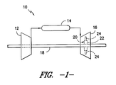
- FIG. 1 illustrates a schematic diagram of a gas turbine 10.
- the gas turbine 10 generally includes a compressor section 12, a combustor section 14 disposed downstream of the compressor section 12, and a turbine section 16 disposed downstream of the combustor section 14. Additionally, the gas turbine 10 may include a shaft 18 coupled between the compressor section 12 and the turbine section 16.
- the turbine section 16 may generally include a turbine rotor 20 having a plurality of structural cases 22 (one of which is shown) and a plurality of turbine airfoil 24 extending radially outwardly from and being coupled to each structural case 22 for rotation therewith. Each structural case 22 may, in turn, be coupled to a portion of the shaft 18 extending through the turbine section 16.
- the compressor section 12 pressurizes air entering the gas turbine 10 and supplies the pressurized air to the combustors of the combustor section 14.
- the pressurized air is mixed with fuel and burned within each combustor to produce hot gases of combustion.
- the hot gases of combustion flow in a hot gas path from the combustor section 14 to the turbine section 16, wherein energy is extracted from the hot gases by the turbine airfoils 24.
- the energy extracted by the turbine airfoils 24 is used to rotate the structural cases 22 which may, in turn, rotate the shaft 18.
- the mechanical rotational energy may then be used to power the compressor section 12 and generate electricity.
- the present disclosure is not limited to use in structural cases 22 in the turbine section 16 of a turbine system 10. Rather, the structural cases 22 and/or turbine airfoils 24 may be utilized in conjunction with any suitable section of the turbine system 10. For example, the structural cases 22 and/or turbine airfoils 24 may, in exemplary embodiments, be utilized in the compressor 12.
- FIGS. 2-6 sequentially show an exemplary method of repairing a tip or cap 36 of an airfoil 30 of a turbine airfoil24.
- the turbine airfoil 24 includes an attachment portion 28 and an airfoil 30 extending from a substantially planar platform 32.
- the platform 32 generally serves as the radially inward boundary for the hot gases of combustion flowing through the turbine section 16 of the gas turbine 10 ( FIG. 1 ).
- the attachment portion 28 may generally be configured to extend radially inwardly from the platform 32 and may include a root structure (not shown), such as a dovetail, configured to secure the airfoil 23 to the structural case 22 of the gas turbine 10 ( FIG. 1 ).
- the airfoil 30 may generally extend radially outwardly from the platform 32 and may include an airfoil base 34 disposed at the platform 32 and an airfoil tip or cap 36 disposed opposite the airfoil base 34.
- the airfoil tip or cap 36 may generally define the radially outermost portion of the turbine airfoil 24.
- the airfoil 30 may also include a pressure side wall 38 and a suction side wall 40 ( FIGS. 3 and 4 ) extending between a leading edge 42 and a trailing edge 44.
- the pressure side wall 38 may generally comprise an aerodynamic, concave outer wall of the airfoil 30.
- the suction side wall 40 may generally define an aerodynamic, convex outer wall of the airfoil 30.
- the turbine airfoil 24 may also include an airfoil cooling circuit 46 extending radially outwardly from the attachment portion 28 for flowing a cooling medium, such as air, water, steam or any other suitable fluid, throughout the airfoil 30.
- the airfoil cooling circuit 46 may generally have any suitable configuration known in the art.
- the cooling circuit 46 may include a plurality of cooling channels or passages 48 (one of which is shown in the cross-sectional view of FIG. 4 ) extending radially within the airfoil 30, such as from the airfoil base 34 to a location generally adjacent the airfoil tip or cap 36.
- the airfoil cooling circuit 46 may be configured as a multiple-pass cooling circuit, with the cooling passages 48 being interconnected and extending radially inward and radially outward within the airfoil 30 (e.g., in a serpentine-like path) such that the cooling medium within the passages 48 flows alternately radially outwardly and radially inwardly throughout the airfoil 30.
- the various components of the turbine airfoil 24 may generally be formed from a ceramic matrix composite (CMC) material.
- CMC ceramic matrix composite
- the CMC material used to form the turbine airfoil 24 may comprise any suitable CMC material known in the art and, thus, may generally include a ceramic matrix having a suitable reinforcing material incorporated therein to enhance the material's properties (e.g., the material strength and/or the thermo-physical properties).
- the CMC material used may be configured as a continuous fiber reinforced CMC material.
- suitable continuous fiber reinforced CMC materials may include, but are not limited to, CMC materials reinforced with continuous carbon fibers, oxide fibers, silicon carbide monofilament fibers or other CMC materials including continuous fiber lay-ups and/or woven fiber performs.
- the CMC material used may be configured as a discontinuous reinforced CMC material.
- suitable discontinuous reinforced CMC materials may include, but are not limited to, particulate, platelet, whisker, discontinuous fiber, in situ and nano-composite reinforced CMC materials or mixtures thereof.
- suitable turbine airfoil 24 may be formed from the CMC material using any suitable manufacturing process known in the art.
- suitable manufacturing processes may include, but are not limited to, injection molding, slip casting, tape casting, infiltration methods (e.g., chemical vapor infiltration, melt infiltration and/or the like) and various other suitable methods and/or processes.
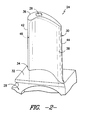
- FIG. 2 illustrates a perspective view of the turbine airfoil 24 having a cavity 26, which can be the result of damage to the tip or cap.
- the term "cavity" refers to any hollow space within the turbine airfoil 24 (e.g., in the airfoil), such as an opening, crack, gap, aperture, hole, etc.
- Such a cavity 26 can be formed on the airfoil 30 through normal use, and generally represents an area where fragments of the original CMC material has been chipped off of the turbine airfoil 24.
- the cavity 26 is located on the tip or cap 36 of the airfoil 30, which is an area that is particularly susceptible to such damage; however, cavities on any portion of the turbine airfoil 24 can be repaired according to the present disclosure.
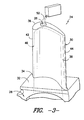
- FIG. 3 shows the addition of a ceramic paste 50 into the cavity 26.
- the ceramic paste 50 can generally be applied at room temperature (i.e., about 20° C to about 25° C) or may be applied at an elevated temperature (e.g., up to about 100° C).
- the ceramic paste 50 can fill the cavity 26 completely, and may be shaped in the desired manner to repair the cavity 26.
- the ceramic paste 50 generally includes a ceramic powder, a binder, and optionally ceramic fibers.
- the ceramic powder can include silicon carbide (SiC), silicon dioxide (SiO2), Alumina oxide (Al203), carbon, or mixtures thereof.
- the binder can include suitable composition configured to hold the ceramic powder (and optional ceramic fibers, if present) together as a paste, and can include but is not limited to, an epoxy binder, a polymeric binder, an adhesive (e.g., glue),silicon dioxide (SiO2), Alumina oxide (A12O3), carbon, boron, or mixtures thereof.
- the ceramic paste 50 includes SiC and an epoxy binder.
- SiC fibers may or may not be included in the ceramic paste 50 if desired.
- the SiC fibers, when included, can be coated to prevent absorption by the CMC matrix exposed on the cavity 26.
- the SiC fibers can be coated with boron (B) or carbon (C) particles, any other suitable particle, or mixtures thereof.
- the ceramic paste 50 can then be heated to remove the binder from the cavity 26, leaving a porous ceramic material 52 in the cavity 26.
- the ceramic paste 50 in the cavity 26 can be heated to 100° C or greater, such as about 110° C to about 200° C. Heating can be achieved either locally (e.g., heating only the porous ceramic material 52 and the immediate area around the cavity 26) or entirely (e.g., heating the entire airfoil 30 and/or turbine airfoil 24).
- the binder in the ceramic paste 50 will begin to decompose, sublimate, and/or evaporate from the ceramic paste 50 to leave only a porous ceramic material 52 in the cavity 26, as shown in FIG. 4 .
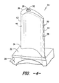
- FIG. 4 shows an intermediary that includes a porous ceramic material 52 (e.g., substantially free from any binder) within the cavity 26.
- the porous ceramic material 52 and cavity 26 can then be further heated to temperatures for receiving a molten ceramic material to fill pores in the porous ceramic material 52, thereby forming a ceramic patch to fill the cavity 26.
- the porous ceramic material 52 and cavity 26 can be heated (either locally or with the entire airfoil 30 and/or turbine airfoil 24) to temperatures of greater than about 1000° C, such as about 1100° C to about 1500°C.
- FIG. 5 shows molten ceramic material 54 added to the heated porous ceramic material 52.
- the molten ceramic material 54 can be added at a temperature that is greater than about 1000° C, such as about 1100° C to about 2000°C. As such, the molten ceramic material 54 can flow and penetrate the pores of the porous ceramic material 52, similar to in melt infusion techniques. Additionally, the molten ceramic material 54 can bond (e.g., thermally, mechanically, chemically, etc.) with the porous ceramic material 52 and/or the CMC material of the turbine airfoil 24 that defines the cavity 26.
- the molten ceramic material 54 can generally include ceramic material, such as silicon carbide (SiC), silicon dioxide (SiO2), Alumina oxide (Al2O3), carbon or mixtures thereof.
- the molten ceramic material 54 can be substantially pure SiC (e.g., being substantially free from other compounds).
- substantially free means no more than an insignificant trace amount present and encompasses completely free (e.g., 0 molar % up to 0.0001 molar %).
- the cavity 26 (and the rest of the turbine airfoil 24) can be cooled, allowing the porous ceramic material 52 and molten ceramic material 54 to cure and set into a ceramic patch 56 filling the cavity 26 ( FIG. 6 ).
- the cavity 26 can be filled with CMC material to repair and refurbish the turbine airfoil.
- the shape of the ceramic patch 56 can be molded as desired either during its formation at any of the above discussed steps or after its formation upon cooling.
- one particular embodiment of the method of repairing a turbine airfoil constructed from a CMC material can be summarized as follows: filling a cavity on a CMC turbine airfoil with a ceramic paste, heating the ceramic paste to remove the binder forming a porous structure in the cavity, further heating the porous structure, adding molten material to fill pores in the porous structure, and cooling the molten material and the porous structure to form a ceramic patch in the cavity. Other steps can be included (e.g., shaping the porous structure, shaping the ceramic patch, etc.) in this method as desired.
Landscapes
- Engineering & Computer Science (AREA)
- Chemical & Material Sciences (AREA)
- Ceramic Engineering (AREA)
- Materials Engineering (AREA)
- Mechanical Engineering (AREA)
- General Engineering & Computer Science (AREA)
- Structural Engineering (AREA)
- Organic Chemistry (AREA)
- Composite Materials (AREA)
- Architecture (AREA)
- Turbine Rotor Nozzle Sealing (AREA)
Abstract
Description
- The present subject matter relates generally to repairing tips or caps for turbine airfoils and, more particularly, to a ceramic-based tip or cap repair for a turbine airfoil.
- In a gas turbine, air is pressurized by a compressor and then mixed with fuel and ignited within an annular array of combustors to generate hot gases of combustion. The hot gases flow from each combustor through a transition piece for flow along an annular hot gas path. Turbine stages are typically disposed along the hot gas path such that the hot gases flow through first-stage nozzles and airfoils and through the nozzles and airfoils of follow-on turbine stages. The turbine airfoils may be secured to a structural case or a plurality of rotor disks comprising the turbine rotor, with each rotor disk being mounted to the rotor shaft for rotation therewith.
- A turbine airfoil generally includes an airfoil extending radially outwardly from a substantially planar platform and an attachment portion extending radially inwardly from the platform for securing the airfoil to one of the rotor disks. Certain airfoils can be composed of ceramic and ceramic matrix composite (CMC) materials for operation in a high temperature environment as exist in gas turbines. After the airfoil is put into service, however, the tip or cap of the rotating CMC airfoil can experience localized damage as the tip or cap comes into contact with a gas turbine shroud or due to foreign object damage. The damage to the CMC airfoil can lead to secondary damage if the CMC or ceramic fibers are exposed to the moisture or other contaminates in the gas turbine hot gas path steam.
- As such, methods would be welcomed for repairing damage to a CMC airfoil, especially on the tip or cap to extend the working life of the airfoil.
- Aspects and advantages of the invention will be set forth in part in the following description, or may be obvious from the description, or may be learned through practice of the invention.
- The invention resides in methods for repairing an article constructed from a CMC material. According to one aspect, a cavity located in the article can be filled with a ceramic paste (e.g., including a ceramic powder and a binder). The ceramic paste in the cavity can then be heated to remove the binder, thereby forming a porous ceramic material. A molten ceramic material can then be added to the porous ceramic material. In one particular embodiment, the cavity can be defined in an airfoil of the turbine airfoil (e.g., on a tip or cap of the airfoil).
- For example, the methods may be used for repairing a tip or cap of an airfoil constructed from a ceramic matrix composite material.
- The invention further resides in intermediates formed during the repair of a turbine airfoil. The intermediate can generally include an airfoil comprising a CMC material, a cavity defined in the airfoil, and a porous ceramic material filling the cavity.
- These and other features, aspects and advantages of the present invention will become better understood with reference to the following description and appended claims. The accompanying drawings, which are incorporated in and constitute a part of this specification, illustrate embodiments of the invention and, together with the description, serve to explain the principles of the invention.
- Embodiments of the present invention will now be described, by way of example only, with reference to the accompanying drawings in which:
-
FIG. 1 illustrates a schematic diagram of one embodiment of a gas turbine; -
FIG. 2 illustrates a perspective view of one embodiment of a turbine airfoil having a cavity formed in the tip or cap of the airfoil after normal use; -
FIG. 3 illustrates filling the cavity in the turbine airfoil shown inFIG. 2 with a ceramic powder mix; -
FIG. 4 illustrates an intermediate having the cavity shown inFIG. 2 filled with a porous ceramic material after heating the ceramic powder mix added as shown inFIG. 3 ; , -
FIG. 5 illustrates filling the porous ceramic material in the cavity shown inFIG. 4 with a molten material; and -
FIG. 6 illustrates the turbine airfoil shown inFIG. 2 after repairing the cavity in the tip or cap. - Reference now will be made in detail to embodiments of the invention, one or more examples of which are illustrated in the drawings. Each example is provided by way of explanation of the invention, not limitation of the invention. In fact, it will be apparent to those skilled in the art that various modifications and variations can be made in the present invention without departing from the scope or spirit of the invention. For instance, features illustrated or described as part of one embodiment can be used with another embodiment to yield a still further embodiment. Thus, it is intended that the present invention covers such modifications and variations as come within the scope of the appended claims and their equivalents.
- In general, methods are generally provided for repairing an article (e.g., a tip or cap of an airfoil in a gas turbine), along with the resulting repaired article (e.g., repaired airfoils). In particular, methods are generally provided for repairing articles (e.g., the tip or cap of an airfoil) constructed from ceramic matrix composite (CMC) material, along with the resulting repaired article (e.g., airfoils). Though discussed hereinafter with respect to an airfoil, the methods may be broadly applied to any article constructed from a CMC material.
- CMC materials used to form the airfoil generally exhibit enhanced high temperature capabilities as compared to conventional metal-based airfoils. As such, the airfoil may reduce or eliminate the need for supplying a cooling medium (e.g., air and the like) to and/or through the tip or cap, thereby increasing the efficiency of the gas turbine. Additionally, because of the low densities of CMC materials, the weight of the tip or cap may be significantly less than conventional metal-based tips or caps, thereby reducing the loads generated by the tip or cap during operation of the gas turbine. In several embodiments of the present subject mater, it should be appreciated that the methods disclosed herein may be designed for retrofit applications and, thus, may be configured to be performed on pre-existing turbine airfoils.
- Referring now to the drawings,
FIG. 1 illustrates a schematic diagram of agas turbine 10. Thegas turbine 10 generally includes a compressor section 12, acombustor section 14 disposed downstream of the compressor section 12, and aturbine section 16 disposed downstream of thecombustor section 14. Additionally, thegas turbine 10 may include ashaft 18 coupled between the compressor section 12 and theturbine section 16. Theturbine section 16 may generally include aturbine rotor 20 having a plurality of structural cases 22 (one of which is shown) and a plurality ofturbine airfoil 24 extending radially outwardly from and being coupled to eachstructural case 22 for rotation therewith. Eachstructural case 22 may, in turn, be coupled to a portion of theshaft 18 extending through theturbine section 16. - During operation of the
gas turbine 10, the compressor section 12 pressurizes air entering thegas turbine 10 and supplies the pressurized air to the combustors of thecombustor section 14. The pressurized air is mixed with fuel and burned within each combustor to produce hot gases of combustion. The hot gases of combustion flow in a hot gas path from thecombustor section 14 to theturbine section 16, wherein energy is extracted from the hot gases by theturbine airfoils 24. The energy extracted by theturbine airfoils 24 is used to rotate thestructural cases 22 which may, in turn, rotate theshaft 18. The mechanical rotational energy may then be used to power the compressor section 12 and generate electricity. - It should be understood, however, that the present disclosure is not limited to use in
structural cases 22 in theturbine section 16 of aturbine system 10. Rather, thestructural cases 22 and/orturbine airfoils 24 may be utilized in conjunction with any suitable section of theturbine system 10. For example, thestructural cases 22 and/orturbine airfoils 24 may, in exemplary embodiments, be utilized in the compressor 12. -
FIGS. 2-6 sequentially show an exemplary method of repairing a tip orcap 36 of anairfoil 30 of a turbine airfoil24.Generally, theturbine airfoil 24 includes anattachment portion 28 and anairfoil 30 extending from a substantiallyplanar platform 32. Theplatform 32 generally serves as the radially inward boundary for the hot gases of combustion flowing through theturbine section 16 of the gas turbine 10 (FIG. 1 ). Theattachment portion 28 may generally be configured to extend radially inwardly from theplatform 32 and may include a root structure (not shown), such as a dovetail, configured to secure the airfoil 23 to thestructural case 22 of the gas turbine 10 (FIG. 1 ). - The
airfoil 30 may generally extend radially outwardly from theplatform 32 and may include anairfoil base 34 disposed at theplatform 32 and an airfoil tip orcap 36 disposed opposite theairfoil base 34. Thus, the airfoil tip orcap 36 may generally define the radially outermost portion of theturbine airfoil 24. Theairfoil 30 may also include apressure side wall 38 and a suction side wall 40 (FIGS. 3 and4 ) extending between a leadingedge 42 and atrailing edge 44. Thepressure side wall 38 may generally comprise an aerodynamic, concave outer wall of theairfoil 30. Similarly, the suction side wall 40 may generally define an aerodynamic, convex outer wall of theairfoil 30. - Additionally, the
turbine airfoil 24 may also include anairfoil cooling circuit 46 extending radially outwardly from theattachment portion 28 for flowing a cooling medium, such as air, water, steam or any other suitable fluid, throughout theairfoil 30. Theairfoil cooling circuit 46 may generally have any suitable configuration known in the art. Thus, in several embodiments, the coolingcircuit 46 may include a plurality of cooling channels or passages 48 (one of which is shown in the cross-sectional view ofFIG. 4 ) extending radially within theairfoil 30, such as from theairfoil base 34 to a location generally adjacent the airfoil tip orcap 36. For example, in one embodiment, theairfoil cooling circuit 46 may be configured as a multiple-pass cooling circuit, with the cooling passages 48 being interconnected and extending radially inward and radially outward within the airfoil 30 (e.g., in a serpentine-like path) such that the cooling medium within the passages 48 flows alternately radially outwardly and radially inwardly throughout theairfoil 30. - It should be appreciated that the various components of the turbine airfoil 24 (e.g., the
airfoil 30,platform 32 and attachment portion 28) may generally be formed from a ceramic matrix composite (CMC) material. In general, the CMC material used to form theturbine airfoil 24 may comprise any suitable CMC material known in the art and, thus, may generally include a ceramic matrix having a suitable reinforcing material incorporated therein to enhance the material's properties (e.g., the material strength and/or the thermo-physical properties). In several embodiments, the CMC material used may be configured as a continuous fiber reinforced CMC material. For example, suitable continuous fiber reinforced CMC materials may include, but are not limited to, CMC materials reinforced with continuous carbon fibers, oxide fibers, silicon carbide monofilament fibers or other CMC materials including continuous fiber lay-ups and/or woven fiber performs. In other embodiments, the CMC material used may be configured as a discontinuous reinforced CMC material. For instance, suitable discontinuous reinforced CMC materials may include, but are not limited to, particulate, platelet, whisker, discontinuous fiber, in situ and nano-composite reinforced CMC materials or mixtures thereof. Moreover, it should be appreciated that the disclosedturbine airfoil 24 may be formed from the CMC material using any suitable manufacturing process known in the art. For example, suitable manufacturing processes may include, but are not limited to, injection molding, slip casting, tape casting, infiltration methods (e.g., chemical vapor infiltration, melt infiltration and/or the like) and various other suitable methods and/or processes. - In normal use, defects can be formed in the
turbine airfoil 24, and particularly along theairfoil 30.FIG. 2 illustrates a perspective view of theturbine airfoil 24 having acavity 26, which can be the result of damage to the tip or cap. As used herein, the term "cavity" refers to any hollow space within the turbine airfoil 24 (e.g., in the airfoil), such as an opening, crack, gap, aperture, hole, etc. Such acavity 26 can be formed on theairfoil 30 through normal use, and generally represents an area where fragments of the original CMC material has been chipped off of theturbine airfoil 24. As shown, thecavity 26 is located on the tip or cap 36 of theairfoil 30, which is an area that is particularly susceptible to such damage; however, cavities on any portion of theturbine airfoil 24 can be repaired according to the present disclosure. -
FIG. 3 shows the addition of aceramic paste 50 into thecavity 26. Theceramic paste 50 can generally be applied at room temperature (i.e., about 20° C to about 25° C) or may be applied at an elevated temperature (e.g., up to about 100° C). In one embodiment, theceramic paste 50 can fill thecavity 26 completely, and may be shaped in the desired manner to repair thecavity 26. - The
ceramic paste 50 generally includes a ceramic powder, a binder, and optionally ceramic fibers. The ceramic powder can include silicon carbide (SiC), silicon dioxide (SiO2), Alumina oxide (Al203), carbon, or mixtures thereof. The binder can include suitable composition configured to hold the ceramic powder (and optional ceramic fibers, if present) together as a paste, and can include but is not limited to, an epoxy binder, a polymeric binder, an adhesive (e.g., glue),silicon dioxide (SiO2), Alumina oxide (A12O3), carbon, boron, or mixtures thereof. - In one particular embodiment, the
ceramic paste 50 includes SiC and an epoxy binder. In this embodiment, SiC fibers may or may not be included in theceramic paste 50 if desired. The SiC fibers, when included, can be coated to prevent absorption by the CMC matrix exposed on thecavity 26. For example, the SiC fibers can be coated with boron (B) or carbon (C) particles, any other suitable particle, or mixtures thereof. - After application into the
cavity 26, theceramic paste 50 can then be heated to remove the binder from thecavity 26, leaving a porousceramic material 52 in the cavity 26.For example, theceramic paste 50 in thecavity 26 can be heated to 100° C or greater, such as about 110° C to about 200° C. Heating can be achieved either locally (e.g., heating only the porousceramic material 52 and the immediate area around the cavity 26) or entirely (e.g., heating theentire airfoil 30 and/or turbine airfoil 24). At these elevated temperatures, the binder in theceramic paste 50 will begin to decompose, sublimate, and/or evaporate from theceramic paste 50 to leave only a porousceramic material 52 in thecavity 26, as shown inFIG. 4 . Specifically,FIG. 4 shows an intermediary that includes a porous ceramic material 52 (e.g., substantially free from any binder) within thecavity 26. - The porous
ceramic material 52 andcavity 26 can then be further heated to temperatures for receiving a molten ceramic material to fill pores in the porousceramic material 52, thereby forming a ceramic patch to fill thecavity 26. For example, the porousceramic material 52 andcavity 26 can be heated (either locally or with theentire airfoil 30 and/or turbine airfoil 24) to temperatures of greater than about 1000° C, such as about 1100° C to about 1500°C. -
FIG. 5 shows moltenceramic material 54 added to the heated porousceramic material 52. The moltenceramic material 54 can be added at a temperature that is greater than about 1000° C, such as about 1100° C to about 2000°C. As such, the moltenceramic material 54 can flow and penetrate the pores of the porousceramic material 52, similar to in melt infusion techniques. Additionally, the moltenceramic material 54 can bond (e.g., thermally, mechanically, chemically, etc.) with the porousceramic material 52 and/or the CMC material of theturbine airfoil 24 that defines thecavity 26. - The molten
ceramic material 54 can generally include ceramic material, such as silicon carbide (SiC), silicon dioxide (SiO2), Alumina oxide (Al2O3), carbon or mixtures thereof. In one embodiment, the moltenceramic material 54 can be substantially pure SiC (e.g., being substantially free from other compounds). As used herein, the term "substantially free" means no more than an insignificant trace amount present and encompasses completely free (e.g., 0 molar % up to 0.0001 molar %). - After infusion of the molten
ceramic material 54, the cavity 26 (and the rest of the turbine airfoil 24) can be cooled, allowing the porousceramic material 52 and moltenceramic material 54 to cure and set into aceramic patch 56 filling the cavity 26 (FIG. 6 ). As such, thecavity 26 can be filled with CMC material to repair and refurbish the turbine airfoil. The shape of theceramic patch 56 can be molded as desired either during its formation at any of the above discussed steps or after its formation upon cooling. - As described in greater detail above, one particular embodiment of the method of repairing a turbine airfoil constructed from a CMC material can be summarized as follows: filling a cavity on a CMC turbine airfoil with a ceramic paste, heating the ceramic paste to remove the binder forming a porous structure in the cavity, further heating the porous structure, adding molten material to fill pores in the porous structure, and cooling the molten material and the porous structure to form a ceramic patch in the cavity. Other steps can be included (e.g., shaping the porous structure, shaping the ceramic patch, etc.) in this method as desired.
- This written description uses examples to disclose the invention, including the best mode, and also to enable any person skilled in the art to practice the invention, including making and using any devices or systems and performing any incorporated methods. The patentable scope of the invention is defmed by the claims, and may include other examples that occur to those skilled in the art. Such other examples are intended to be within the scope of the claims if they include structural elements that do not differ from the literal language of the claims, or if they include equivalent structural elements with insubstantial differences from the literal languages of the claims.
Claims (15)
- A method of repairing an article constructed from a ceramic matrix composite material, the method comprising:filling a cavity (26) located in the article with a ceramic paste (50), wherein the ceramic paste (50) comprises a ceramic powder and a binder;heating the ceramic paste (50) in the cavity (26) to remove the binder, thereby forming a porous ceramic material (52); andadding a molten ceramic material (54) to the porous ceramic material (52).
- The method of claim 1, wherein the porous ceramic material (52) is heated to about 100° C or higher to remove the binder.
- The method of claim 1 or 2, wherein the ceramic paste (50) is substantially free from a ceramic fiber.
- The method of claim 1 or 2, wherein the ceramic paste (50) further comprises a ceramic fiber.
- The method of claim 4, wherein the ceramic fiber comprises silicon carbide.
- The method of claim 4 or 5, wherein the ceramic fiber is coated with particles.
- The method of claim 6, wherein the particles comprise boron, carbon, or mixtures thereof.
- The method of any preceding claim, further comprising:heating the porous ceramic material (52) to a temperature of about 1000° C to about 1500° C prior to adding the molten ceramic material (54).
- The method of any preceding claim, wherein the molten ceramic material (54) is added to the porous ceramic material (52) at a temperature of about 1000° C to about 2000° C.
- The method of any preceding claim, further comprising, after adding the molten ceramic material (54):cooling the porous ceramic material (52) and molten ceramic material (54) to form a ceramic patch (56) in the cavity (26).
- The method of claim 10, further comprising:shaping the ceramic patch (56).
- The method of any preceding claim, wherein the molten ceramic material (54) comprises silicon carbide.
- The method of any preceding claim, wherein heating the porous ceramic material (52) to remove the binder is achieved locally.
- The method of any preceding claim, wherein the article is a turbine airfoil (24).
- An intermediate formed during the repair of a turbine airfoil (24), the intermediate comprising:an air foil (24) comprising a ceramic matrix composite material;a cavity (26) defined in the airfoil (24); anda porous ceramic material (52) filling the cavity (26).
Applications Claiming Priority (1)
| Application Number | Priority Date | Filing Date | Title |
|---|---|---|---|
| US13/188,755 US20130022471A1 (en) | 2011-07-22 | 2011-07-22 | Methods for repairing a turbine airfoil constructed from cmc material |
Publications (2)
| Publication Number | Publication Date |
|---|---|
| EP2570591A2 true EP2570591A2 (en) | 2013-03-20 |
| EP2570591A3 EP2570591A3 (en) | 2015-11-11 |
Family
ID=46551396
Family Applications (1)
| Application Number | Title | Priority Date | Filing Date |
|---|---|---|---|
| EP12176637.2A Withdrawn EP2570591A3 (en) | 2011-07-22 | 2012-07-17 | Method for repairing a ceramic fiber reinforced ceramic composite article and corresponding intermediate |
Country Status (3)
| Country | Link |
|---|---|
| US (2) | US20130022471A1 (en) |
| EP (1) | EP2570591A3 (en) |
| CN (1) | CN102887727A (en) |
Families Citing this family (17)
| Publication number | Priority date | Publication date | Assignee | Title |
|---|---|---|---|---|
| US9895716B2 (en) * | 2013-04-17 | 2018-02-20 | General Electric Company | Repair process and a repaired component |
| US9701072B2 (en) * | 2013-10-30 | 2017-07-11 | General Electric Company | Methods of repairing matrix cracks in melt infiltrated ceramic matrix composites |
| US9382801B2 (en) | 2014-02-26 | 2016-07-05 | General Electric Company | Method for removing a rotor bucket from a turbomachine rotor wheel |
| US9512505B2 (en) | 2014-10-23 | 2016-12-06 | General Electric Company | Methods and compositions for repair of composite materials |
| US10202854B2 (en) | 2014-12-18 | 2019-02-12 | Rolls-Royce North America Technologies, Inc. | Abrasive tips for ceramic matrix composite blades and methods for making the same |
| US10834790B2 (en) | 2014-12-22 | 2020-11-10 | Rolls-Royce High Temperature Composites, Inc. | Method for making ceramic matrix composite articles with progressive melt infiltration |
| US10406640B2 (en) | 2014-12-22 | 2019-09-10 | Rolls-Royce High Temperature Composites, Inc. | Method for repairing ceramic matrix composite (CMC) articles |
| US10697305B2 (en) * | 2016-01-08 | 2020-06-30 | General Electric Company | Method for making hybrid ceramic/metal, ceramic/ceramic body by using 3D printing process |
| US20180005191A1 (en) * | 2016-06-30 | 2018-01-04 | Xerox Corporation | Method and system for ranking questions for job interview |
| US10774648B2 (en) | 2016-10-04 | 2020-09-15 | General Electric Company | Methods and features for CMC component repairs |
| US10150188B1 (en) * | 2017-08-04 | 2018-12-11 | General Electric Company | Method of ceramic matrix composite repair |
| US11292217B2 (en) * | 2018-05-31 | 2022-04-05 | General Electric Company | Composite component void repair |
| WO2021021231A1 (en) | 2019-07-30 | 2021-02-04 | Siemens Energy, Inc. | System and method for repairing high-temperature gas turbine components |
| US11504813B2 (en) | 2020-05-18 | 2022-11-22 | Rolls-Royce Plc | Methods for health monitoring of ceramic matrix composite components in gas turbine engines |
| US11969962B2 (en) | 2020-09-25 | 2024-04-30 | General Electric Company | Method for repairing composite components and associated infiltration systems and methods |
| US11814979B1 (en) * | 2022-09-21 | 2023-11-14 | Rtx Corporation | Systems and methods of hybrid blade tip repair |
| FR3155229A1 (en) | 2023-11-14 | 2025-05-16 | Safran Ceramics | Repair of ceramic matrix composite material parts |
Family Cites Families (9)
| Publication number | Priority date | Publication date | Assignee | Title |
|---|---|---|---|---|
| US5156321A (en) * | 1990-08-28 | 1992-10-20 | Liburdi Engineering Limited | Powder metallurgy repair technique |
| US6820334B2 (en) * | 2002-04-19 | 2004-11-23 | General Electric Company | Method for repairing articles of ceramic composites |
| US6875464B2 (en) * | 2003-04-22 | 2005-04-05 | General Electric Company | In-situ method and composition for repairing a thermal barrier coating |
| CN1448363A (en) * | 2003-05-01 | 2003-10-15 | 东南大学 | High-strength anchor grouting agent |
| FR2876687B1 (en) * | 2004-10-20 | 2007-01-26 | Air Liquide | PROCESS FOR FILLING A CONTAINER WITH A MICROPOROUS MASS |
| FR2906172A1 (en) * | 2006-09-22 | 2008-03-28 | Snecma Services Sa | Blade`s defect e.g. crack, repairing method for e.g. low pressure distributor part, of aircraft`s turbomachine, involves heating damaging zone by generating induced current using inductor for passing powder to liquid state |
| CN100575307C (en) * | 2006-10-31 | 2009-12-30 | 重庆钢铁(集团)有限责任公司 | Shaft Furnace Lining Repair Material and Its Application |
| WO2010123602A1 (en) * | 2009-01-28 | 2010-10-28 | Applied Thin Films Inc. | High temperature stable amorphous silica-rich aluminosilicates |
| CN101717254A (en) * | 2009-12-01 | 2010-06-02 | 陕西盛华冶化有限公司 | Masonry material of silicon-calcium-iron alloy furnace taphole and maintaining technology |
-
2011
- 2011-07-22 US US13/188,755 patent/US20130022471A1/en not_active Abandoned
-
2012
- 2012-07-17 EP EP12176637.2A patent/EP2570591A3/en not_active Withdrawn
- 2012-07-20 CN CN2012102544275A patent/CN102887727A/en active Pending
-
2014
- 2014-05-05 US US14/269,240 patent/US20140241900A1/en not_active Abandoned
Non-Patent Citations (1)
| Title |
|---|
| None |
Also Published As
| Publication number | Publication date |
|---|---|
| US20140241900A1 (en) | 2014-08-28 |
| US20130022471A1 (en) | 2013-01-24 |
| CN102887727A (en) | 2013-01-23 |
| EP2570591A3 (en) | 2015-11-11 |
Similar Documents
| Publication | Publication Date | Title |
|---|---|---|
| EP2570591A2 (en) | Method for repairing a ceramic fiber reinforced ceramic composite article and corresponding intermediate | |
| US9410437B2 (en) | Airfoil components containing ceramic-based materials and processes therefor | |
| CN102678188B (en) | Turbine blade | |
| CN103183519B (en) | Form the method and ceramic matrix composite component of ceramic matrix composite | |
| US8777583B2 (en) | Turbine airfoil components containing ceramic-based materials and processes therefor | |
| US8721290B2 (en) | Processes for producing components containing ceramic-based and metallic materials | |
| CA2867913C (en) | Process for producing ceramic composite components | |
| US8980435B2 (en) | CMC component, power generation system and method of forming a CMC component | |
| US9228445B2 (en) | Turbine airfoil components containing ceramic-based materials and processes therefor | |
| US8777582B2 (en) | Components containing ceramic-based materials and coatings therefor | |
| US20160312626A1 (en) | Method for fabricating a ceramic matrix composite rotor blade | |
| US8734107B2 (en) | Ceramic-based tip cap for a turbine bucket | |
| US20170328223A1 (en) | Hybrid ceramic matrix composite materials | |
| US20140199174A1 (en) | Method of forming a ceramic matrix composite component, a ceramic matrix composite component and a tip member | |
| WO2020018090A1 (en) | Hybrid components having an intermediate ceramic fiber material |
Legal Events
| Date | Code | Title | Description |
|---|---|---|---|
| PUAI | Public reference made under article 153(3) epc to a published international application that has entered the european phase |
Free format text: ORIGINAL CODE: 0009012 |
|
| AK | Designated contracting states |
Kind code of ref document: A2 Designated state(s): AL AT BE BG CH CY CZ DE DK EE ES FI FR GB GR HR HU IE IS IT LI LT LU LV MC MK MT NL NO PL PT RO RS SE SI SK SM TR |
|
| AX | Request for extension of the european patent |
Extension state: BA ME |
|
| PUAL | Search report despatched |
Free format text: ORIGINAL CODE: 0009013 |
|
| AK | Designated contracting states |
Kind code of ref document: A3 Designated state(s): AL AT BE BG CH CY CZ DE DK EE ES FI FR GB GR HR HU IE IS IT LI LT LU LV MC MK MT NL NO PL PT RO RS SE SI SK SM TR |
|
| AX | Request for extension of the european patent |
Extension state: BA ME |
|
| RIC1 | Information provided on ipc code assigned before grant |
Ipc: F01D 5/28 20060101ALI20151008BHEP Ipc: C04B 35/80 20060101ALI20151008BHEP Ipc: F01D 5/00 20060101AFI20151008BHEP |
|
| STAA | Information on the status of an ep patent application or granted ep patent |
Free format text: STATUS: THE APPLICATION IS DEEMED TO BE WITHDRAWN |
|
| 18D | Application deemed to be withdrawn |
Effective date: 20160512 |