EP2570366A2 - Quick-mounting device for canister - Google Patents
Quick-mounting device for canister Download PDFInfo
- Publication number
- EP2570366A2 EP2570366A2 EP12004317A EP12004317A EP2570366A2 EP 2570366 A2 EP2570366 A2 EP 2570366A2 EP 12004317 A EP12004317 A EP 12004317A EP 12004317 A EP12004317 A EP 12004317A EP 2570366 A2 EP2570366 A2 EP 2570366A2
- Authority
- EP
- European Patent Office
- Prior art keywords
- housing
- arched
- quick
- mounting device
- piece
- Prior art date
- Legal status (The legal status is an assumption and is not a legal conclusion. Google has not performed a legal analysis and makes no representation as to the accuracy of the status listed.)
- Granted
Links
Images
Classifications
-
- B—PERFORMING OPERATIONS; TRANSPORTING
- B65—CONVEYING; PACKING; STORING; HANDLING THIN OR FILAMENTARY MATERIAL
- B65D—CONTAINERS FOR STORAGE OR TRANSPORT OF ARTICLES OR MATERIALS, e.g. BAGS, BARRELS, BOTTLES, BOXES, CANS, CARTONS, CRATES, DRUMS, JARS, TANKS, HOPPERS, FORWARDING CONTAINERS; ACCESSORIES, CLOSURES, OR FITTINGS THEREFOR; PACKAGING ELEMENTS; PACKAGES
- B65D83/00—Containers or packages with special means for dispensing contents
- B65D83/14—Containers for dispensing liquid or semi-liquid contents by internal gaseous pressure, i.e. aerosol containers comprising propellant
- B65D83/16—Actuating means
- B65D83/26—Actuating means operating automatically, e.g. periodically
- B65D83/262—Actuating means operating automatically, e.g. periodically by clockwork, motor, electric or magnetic means operating without repeated human input
-
- B—PERFORMING OPERATIONS; TRANSPORTING
- B05—SPRAYING OR ATOMISING IN GENERAL; APPLYING FLUENT MATERIALS TO SURFACES, IN GENERAL
- B05B—SPRAYING APPARATUS; ATOMISING APPARATUS; NOZZLES
- B05B11/00—Single-unit hand-held apparatus in which flow of contents is produced by the muscular force of the operator at the moment of use
- B05B11/0005—Components or details
- B05B11/0008—Sealing or attachment arrangements between sprayer and container
-
- B—PERFORMING OPERATIONS; TRANSPORTING
- B65—CONVEYING; PACKING; STORING; HANDLING THIN OR FILAMENTARY MATERIAL
- B65D—CONTAINERS FOR STORAGE OR TRANSPORT OF ARTICLES OR MATERIALS, e.g. BAGS, BARRELS, BOTTLES, BOXES, CANS, CARTONS, CRATES, DRUMS, JARS, TANKS, HOPPERS, FORWARDING CONTAINERS; ACCESSORIES, CLOSURES, OR FITTINGS THEREFOR; PACKAGING ELEMENTS; PACKAGES
- B65D83/00—Containers or packages with special means for dispensing contents
- B65D83/14—Containers for dispensing liquid or semi-liquid contents by internal gaseous pressure, i.e. aerosol containers comprising propellant
- B65D83/16—Actuating means
- B65D83/20—Actuator caps
-
- B—PERFORMING OPERATIONS; TRANSPORTING
- B65—CONVEYING; PACKING; STORING; HANDLING THIN OR FILAMENTARY MATERIAL
- B65D—CONTAINERS FOR STORAGE OR TRANSPORT OF ARTICLES OR MATERIALS, e.g. BAGS, BARRELS, BOTTLES, BOXES, CANS, CARTONS, CRATES, DRUMS, JARS, TANKS, HOPPERS, FORWARDING CONTAINERS; ACCESSORIES, CLOSURES, OR FITTINGS THEREFOR; PACKAGING ELEMENTS; PACKAGES
- B65D83/00—Containers or packages with special means for dispensing contents
- B65D83/14—Containers for dispensing liquid or semi-liquid contents by internal gaseous pressure, i.e. aerosol containers comprising propellant
- B65D83/38—Details of the container body
- B65D83/388—Details of the container body with means for suspending the aerosol container
-
- B—PERFORMING OPERATIONS; TRANSPORTING
- B05—SPRAYING OR ATOMISING IN GENERAL; APPLYING FLUENT MATERIALS TO SURFACES, IN GENERAL
- B05B—SPRAYING APPARATUS; ATOMISING APPARATUS; NOZZLES
- B05B15/00—Details of spraying plant or spraying apparatus not otherwise provided for; Accessories
- B05B15/60—Arrangements for mounting, supporting or holding spraying apparatus
-
- B—PERFORMING OPERATIONS; TRANSPORTING
- B05—SPRAYING OR ATOMISING IN GENERAL; APPLYING FLUENT MATERIALS TO SURFACES, IN GENERAL
- B05B—SPRAYING APPARATUS; ATOMISING APPARATUS; NOZZLES
- B05B9/00—Spraying apparatus for discharge of liquids or other fluent material, without essentially mixing with gas or vapour
- B05B9/03—Spraying apparatus for discharge of liquids or other fluent material, without essentially mixing with gas or vapour characterised by means for supplying liquid or other fluent material
- B05B9/04—Spraying apparatus for discharge of liquids or other fluent material, without essentially mixing with gas or vapour characterised by means for supplying liquid or other fluent material with pressurised or compressible container; with pump
- B05B9/08—Apparatus to be carried on or by a person, e.g. of knapsack type
- B05B9/0805—Apparatus to be carried on or by a person, e.g. of knapsack type comprising a pressurised or compressible container for liquid or other fluent material
-
- B—PERFORMING OPERATIONS; TRANSPORTING
- B65—CONVEYING; PACKING; STORING; HANDLING THIN OR FILAMENTARY MATERIAL
- B65D—CONTAINERS FOR STORAGE OR TRANSPORT OF ARTICLES OR MATERIALS, e.g. BAGS, BARRELS, BOTTLES, BOXES, CANS, CARTONS, CRATES, DRUMS, JARS, TANKS, HOPPERS, FORWARDING CONTAINERS; ACCESSORIES, CLOSURES, OR FITTINGS THEREFOR; PACKAGING ELEMENTS; PACKAGES
- B65D83/00—Containers or packages with special means for dispensing contents
- B65D83/14—Containers for dispensing liquid or semi-liquid contents by internal gaseous pressure, i.e. aerosol containers comprising propellant
- B65D83/40—Closure caps
Definitions
- the present invention relates to a quick-mounting device that can quickly and conveniently mount a canister for spraying a mist of an agent, such as air fresheners, disinfectants, detergents, cosmetics, insect repellents or similar substances.
- an agent such as air fresheners, disinfectants, detergents, cosmetics, insect repellents or similar substances.
- a conventional spray device for aromatic liquid is provided with a hinged clamp that can clamp a neck of a canister.
- the spray device can be pressed to release a mist of an aromatic agent to allow a room full of good smell to overcome the original odor of the room.
- the hinged clamp can be opened again to allow the neck of an exhausted canister to be released from the clamp.
- some clamps cannot be opened more than 60 degrees, and thus the user cannot clearly see the coupling status of a canister, so that the replacement is not easy and cannot be accomplished in one operation.
- the applicant has contrive a quick-mounting device that can quickly and conveniently dismount an exhausted canister and mount a new canister for spraying aromatic agent.
- the primary object of the present invention is to provide a quick-mounting device that can mount a canister quickly and conveniently.
- the quick-mounting device is implemented to comprise a housing and an adjustment means.
- the housing defines a recess at a top thereof and a hollow space therein, the recess being defined by a circumferential surface and a bottom surface.
- the housing is sealed with a cover that defines a though hole at a center thereof
- the adjustment means includes two arched pieces and a control piece.
- the arched pieces are placed in the recess of the housing to define an opening therebetween, wherein the opening communicates with the through hole of the cover and the hollow space of the housing.
- the control piece has a pusher and is placed on top of the arched pieces to engage with two ends of each arched piece.
- Each arched piece is provided with a spring at an external side thereof intermediate of the two ends to be elastically engaged with the housing. Thereby, the pusher of the control piece of the adjustment means can be pressed to have the two arched pieces moved outwardly to change the dimension of the opening defined by the two arched pieces so as to mount a canister.
- the circumferential surface of the recess of the housing is defined with a first pair of opposing recesses and a second pair of opposing recesses, the first pair of opposing recesses being located at an orientation about 90 degrees relative to the second pair of opposing recesses.
- control piece is formed into a generally annular piece having two opposing projections, one of which is formed with the pusher, each projection being provided with an engaging protrusion on a bottom surface thereof
- Each of the two ends of each arched piece is formed with a sloping surface.
- Each of the arched pieces is formed with two protrusions and a boss therebetween at an external side intermediate of the two ends for engaging with a corresponding spring.
- each engaging protrusion of the control piece of the adjustment means has two sides formed into a general V-shape for mating with two corresponding slopping surfaces respectively on the two arched pieces
- each arched piece of the adjustment means is formed with a sharp edge along an internal side thereof.
- the bottom surface of the recess of the housing is defined with multiple grooves to be inserted with protrusions, which are formed on bottom surfaces of the arched pieces.
- the housing defines a plurality of first holes on a top thereof, and the cover defines a plurality of second holes corresponding to the first holes, so that the cover can be sealed with the housing by using fastening members through the first and second holes.
- two opposing lugs are provided on the cover across the through hole of the cover.
- the quick mounting device 1 comprises a housing 11 and an adjustment means 12.
- the housing 11 defines a recess 112 at a top thereof and a hollow space 111 therein, the recess 112 being defined by a circumferential surface and a bottom surface.
- the circumferential surface of the recess 112 of the housing 11 is defined with a first pair of opposing recesses 113, 114, and a second pair of opposing recesses 115, the first pair of opposing recesses 113, 114 being located at an orientation about 90 degrees relative to the second pair of opposing recesses 115.
- the line formed by the first pair of the opposing recesses 113, 114 is perpendicular to the line formed by the second pair of the opposing recesses 115.
- the bottom surface of the recess 112 of the housing 11 is defined with multiple grooves 116.
- the housing 11 is sealed with a cover 117 that defines a though hole at a center thereof
- the housing 11 defines a plurality of first holes on a top thereof, and the cover 117 defines a plurality of second holes corresponding to the first holes, so that the cover 117 can be sealed with the housing 11 by using fastening members through the first and second holes.
- two opposing lugs 118 are provided on the cover 117 across the through hole of the cover 117.
- the adjustment means 12 includes two arched pieces 124 and a control piece 121.
- the arched pieces 121 are placed in the recess 112 of the housing 11 to define an opening therebetween, wherein the opening communicates with the through hole of the cover 117 and the hollow space 111 of the housing 11.
- the control piece 121 has a pusher 122 and is placed on top of the arched pieces 124 to engage with two ends of each arched piece 124, each arched piece 124 being provided with a spring 131 at an external side thereof intermediate of the two ends to be elastically engaged with the housing 11. As shown in FIGS. 3 and 4 , the two ends of each arched piece 124 are respectively formed with sloping surfaces 127, 128.
- Each of the arched pieces 124 is formed with two protrusions 125 and a boss 126 between the two protrusions 125 at the external side intermediate of the two ends for engaging with a corresponding spring 131.
- the control piece 121 is formed into a generally annular piece having two opposing projections, one of which is formed with the pusher 122, which has a large area.
- the control piece 121 has a central opening.
- Each projection is provided with an engaging protrusion 123 at a bottom surface thereof.
- Each of the engaging portions 123 has two sides formed into a general V-shape for mating with two corresponding slopping surfaces respectively on the two arched pieces 124.
- each arched piece 124 of the adjustment means 12 is formed with protrusions 129 on a bottom surface thereof to be inserted into the grooves 116 of the housing 11.
- Each arched piece 124 of the adjustment means 12 is formed with a sharp edge 130 along an internal side thereof.
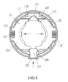
- the sharp edges 130 of the arched pieces 124 are located to face to each other; the spring 131 is mounted around the boss 126; the control piece 121 is placed on top of the two arched pieces 124, wherein the sharp edges 130 extend to partly cover the central opening of the control piece 121 (see FIG 5 ). Also the protrusions 123 are placed to contact with the sloping surfaces 127, 128 by their two sides formed into a general V-shape. As shown in FIG 5 , the control piece 121 of the adjustment means 12 is placed in the recess 112 of the housing 11, wherein the two projections (one with the pusher 122) are placed in the recesses 113, 114.
- the protrusions 129 of the two arched pieces 124 are placed in the grooves 116 defined in the bottom surface of the recess 112.
- the spring 131 and the protrusions 125 are placed in the recesses 115 defined in the circumferential surface of the recess 112 of the housing 11.
- a user may press the pusher 122 to allow the generally V-shaped protrusion 123 to push the sloping surfaces 127, 128 to move the two arched piece 124 outwardly so that the canister 14 can be fitted in the housing 11 from the bottom. Thereafter, the user may release the pusher 122 to allow the springs 131 to restore to their original positions so that the sharp edges 130 of the arched pieces 124 can clamp a neck 142 of the canister 14 so that the canister 14 can be mounted quickly and properly. Similarly, the canister 14 can be quickly dismounted in the same manner.
- the present invention has the following advantages over the prior art.
Landscapes
- Chemical & Material Sciences (AREA)
- Dispersion Chemistry (AREA)
- Engineering & Computer Science (AREA)
- Mechanical Engineering (AREA)
- Casings For Electric Apparatus (AREA)
- Supplying Secondary Fuel Or The Like To Fuel, Air Or Fuel-Air Mixtures (AREA)
- Clamps And Clips (AREA)
- Connection Of Plates (AREA)
Abstract
Description
- The present invention relates to a quick-mounting device that can quickly and conveniently mount a canister for spraying a mist of an agent, such as air fresheners, disinfectants, detergents, cosmetics, insect repellents or similar substances.
- Due to the development of economy and human civilization, the material and spiritual aspects of life are being paid more and more attention. Everyone is actively pursuing the goal of good living environment. To have offices, rooms or cars without special smell or remove the turbidity of the air, they are typically equipped with air-conditioning equipments, air cleaners, etc, to allow persons therein to improve the work efficiency and have better mental state. Alternatively, they can be provided with aromatic agents, electric air fresheners, perfumes so as to eliminate unpleasant odor. Many products for eliminating the air smell are available from the market.
- A conventional spray device for aromatic liquid is provided with a hinged clamp that can clamp a neck of a canister. The spray device can be pressed to release a mist of an aromatic agent to allow a room full of good smell to overcome the original odor of the room. When replacing with a canister, the hinged clamp can be opened again to allow the neck of an exhausted canister to be released from the clamp. However, some clamps cannot be opened more than 60 degrees, and thus the user cannot clearly see the coupling status of a canister, so that the replacement is not easy and cannot be accomplished in one operation.
- To overcome the drawback of the conventional spray device, the applicant has contrive a quick-mounting device that can quickly and conveniently dismount an exhausted canister and mount a new canister for spraying aromatic agent.
- The primary object of the present invention is to provide a quick-mounting device that can mount a canister quickly and conveniently.
- To achieve the above object, the quick-mounting device is implemented to comprise a housing and an adjustment means. The housing defines a recess at a top thereof and a hollow space therein, the recess being defined by a circumferential surface and a bottom surface. The housing is sealed with a cover that defines a though hole at a center thereof The adjustment means includes two arched pieces and a control piece. The arched pieces are placed in the recess of the housing to define an opening therebetween, wherein the opening communicates with the through hole of the cover and the hollow space of the housing. The control piece has a pusher and is placed on top of the arched pieces to engage with two ends of each arched piece. Each arched piece is provided with a spring at an external side thereof intermediate of the two ends to be elastically engaged with the housing. Thereby, the pusher of the control piece of the adjustment means can be pressed to have the two arched pieces moved outwardly to change the dimension of the opening defined by the two arched pieces so as to mount a canister.
- Furthermore, the circumferential surface of the recess of the housing is defined with a first pair of opposing recesses and a second pair of opposing recesses, the first pair of opposing recesses being located at an orientation about 90 degrees relative to the second pair of opposing recesses.
- Still furthermore, the control piece is formed into a generally annular piece having two opposing projections, one of which is formed with the pusher, each projection being provided with an engaging protrusion on a bottom surface thereof Each of the two ends of each arched piece is formed with a sloping surface. Each of the arched pieces is formed with two protrusions and a boss therebetween at an external side intermediate of the two ends for engaging with a corresponding spring.
- Still furthermore, each engaging protrusion of the control piece of the adjustment means has two sides formed into a general V-shape for mating with two corresponding slopping surfaces respectively on the two arched pieces
- Still furthermore, each arched piece of the adjustment means is formed with a sharp edge along an internal side thereof.
- Still furthermore, the bottom surface of the recess of the housing is defined with multiple grooves to be inserted with protrusions, which are formed on bottom surfaces of the arched pieces.
- Still furthermore, the housing defines a plurality of first holes on a top thereof, and the cover defines a plurality of second holes corresponding to the first holes, so that the cover can be sealed with the housing by using fastening members through the first and second holes.
- Still furthermore, two opposing lugs are provided on the cover across the through hole of the cover.
- Other objects, advantages, and novel features of the present invention will become more apparent from the following detailed description when taken in conjunction with the accompanying drawings.
-
-
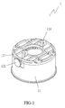
FIG 1 is a 3-dimensional view of one embodiment according to the present invention. -
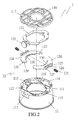
FIG 2 is an exploded view of the embodiment according to the present invention. -
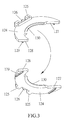
FIG 3 shows two 3-dimension views of an ached piece of the embodiment respectively seen from different directions. -
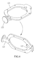
FIG 4 shows two 3-dimension views of a control piece of the embodiment respectively seen from different directions. -
FIG 5 is a sectional view of the embodiment showing an operational status of the control piece. -
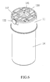
FIG 6 is a 3-dimensional view of the embodiment, which has mounted a canister. -
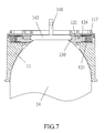
FIG 7 is a sectional view of the embodiment, which has mounted a canister. - Turning now to
FIGS. 1 and2 , one embodiment of a quick-mounting device for canisters according to the present invention is illustrated. Thequick mounting device 1 comprises ahousing 11 and an adjustment means 12. Thehousing 11 defines arecess 112 at a top thereof and ahollow space 111 therein, therecess 112 being defined by a circumferential surface and a bottom surface. The circumferential surface of therecess 112 of thehousing 11 is defined with a first pair ofopposing recesses opposing recesses 115, the first pair ofopposing recesses opposing recesses 115. That is to say, the line formed by the first pair of theopposing recesses opposing recesses 115. Furthermore, the bottom surface of therecess 112 of thehousing 11 is defined with multiple grooves 116.Thehousing 11 is sealed with acover 117 that defines a though hole at a center thereof Thehousing 11 defines a plurality of first holes on a top thereof, and thecover 117 defines a plurality of second holes corresponding to the first holes, so that thecover 117 can be sealed with thehousing 11 by using fastening members through the first and second holes. Also, twoopposing lugs 118 are provided on thecover 117 across the through hole of thecover 117. - The adjustment means 12 includes two
arched pieces 124 and acontrol piece 121. Thearched pieces 121 are placed in therecess 112 of thehousing 11 to define an opening therebetween, wherein the opening communicates with the through hole of thecover 117 and thehollow space 111 of thehousing 11. Thecontrol piece 121 has apusher 122 and is placed on top of thearched pieces 124 to engage with two ends of eacharched piece 124, eacharched piece 124 being provided with aspring 131 at an external side thereof intermediate of the two ends to be elastically engaged with thehousing 11. As shown inFIGS. 3 and4 , the two ends of eacharched piece 124 are respectively formed with slopingsurfaces arched pieces 124 is formed with twoprotrusions 125 and aboss 126 between the twoprotrusions 125 at the external side intermediate of the two ends for engaging with acorresponding spring 131. In more detail, thecontrol piece 121 is formed into a generally annular piece having two opposing projections, one of which is formed with thepusher 122, which has a large area. Thecontrol piece 121 has a central opening. Each projection is provided with anengaging protrusion 123 at a bottom surface thereof. Each of theengaging portions 123 has two sides formed into a general V-shape for mating with two corresponding slopping surfaces respectively on the twoarched pieces 124. Furthermore, eacharched piece 124 of the adjustment means 12 is formed withprotrusions 129 on a bottom surface thereof to be inserted into thegrooves 116 of thehousing 11. Eacharched piece 124 of the adjustment means 12 is formed with asharp edge 130 along an internal side thereof. - As shown, the
sharp edges 130 of thearched pieces 124 are located to face to each other; thespring 131 is mounted around theboss 126; thecontrol piece 121 is placed on top of the twoarched pieces 124, wherein thesharp edges 130 extend to partly cover the central opening of the control piece 121 (seeFIG 5 ). Also theprotrusions 123 are placed to contact with thesloping surfaces FIG 5 , thecontrol piece 121 of the adjustment means 12 is placed in therecess 112 of thehousing 11, wherein the two projections (one with the pusher 122) are placed in therecesses protrusions 129 of the twoarched pieces 124 are placed in thegrooves 116 defined in the bottom surface of therecess 112. Thespring 131 and theprotrusions 125 are placed in therecesses 115 defined in the circumferential surface of therecess 112 of thehousing 11. Thereby, thepusher 112 of thecontrol piece 121 of the adjustment means 12 can be pressed to overcome the compressional force of eachspring 131 to have the twoarched pieces 124 moved outwardly via theprotrusions 123 pushing thesloping surfaces sharp edges 130 of the twoarched pieces 124. - As shown in
FIGS. 6 and7 , when mounting acanister 14, a user may press thepusher 122 to allow the generally V-shaped protrusion 123 to push thesloping surfaces arched piece 124 outwardly so that thecanister 14 can be fitted in thehousing 11 from the bottom. Thereafter, the user may release thepusher 122 to allow thesprings 131 to restore to their original positions so that thesharp edges 130 of thearched pieces 124 can clamp aneck 142 of thecanister 14 so that thecanister 14 can be mounted quickly and properly. Similarly, thecanister 14 can be quickly dismounted in the same manner. - Accordingly, the present invention has the following advantages over the prior art.
- 1. An exhausted canister can be quickly and conveniently dismounted by pressing a
pusher 122 of the present invention to allow thesharp edges 130 of the two arched pieces 24 to clear of theneck 124 of the canister so as to release the canister. - 2. A canister can be quickly and conveniently mounted without a need to see the clamping status of the canister in the mounting process.
- Although the present invention has been described with a certain degree of particularity, it is understood that the present disclosure is made by way of example only and the combination and arrangement of parts may be resorted to without departing from the spirit and scope of the invention hereinafter claimed.
Claims (8)
- A quick-mounting device for canisters comprising:a housing defining a recess at a top thereof and a hollow space therein, said recess being defined by a circumferential surface and a bottom surface, said housing being sealed with a cover that defines a though hole at a center thereof; andan adjustment means including two arched pieces and a control piece, said arched pieces being placed in said recess of said housing to define an opening therebetween, said opening communicating with said through hole of said cover and said hollow space of said housing, said control piece having a pusher and being placed on top of said arched pieces to engage with two ends of each said arched piece, each said arched piece being provided with a spring at an external side thereof intermediate of the two ends to be elastically engaged with said housing; whereby said pusher of said control piece of said adjustment means can be pressed to have two said arched pieces moved outwardly so as to change the dimension of said opening defined by two said arched pieces.
- A quick-mounting device for canisters according to claim 1, wherein the circumferential surface of said recess of said housing is defined with a first pair of opposing recesses and a second pair of opposing recesses, the first pair of opposing recesses being located at an orientation about 90 degrees relative to the second pair of opposing recesses.
- A quick-mounting device for canisters according to claim 1 or 2, wherein said control piece is formed into a generally annular piece having two opposing projections, one of which is formed with the pusher, each said projection being provided with an engaging protrusion on a bottom surface thereof; and wherein each of the two ends of each said arched piece is formed with a sloping surface, each of said arched pieces is formed with two protrusions and a boss therebetween at an external side intermediate of the two ends for engaging with a corresponding spring.
- A quick-mounting device for canisters according to claim 3, wherein each said engaging protrusion of said control piece of said adjustment means has two sides formed into a general \/-shape for mating with two corresponding slopping surfaces respectively on two said arched pieces.
- A quick-mounting device for canisters according to any one of the preceding claims, wherein each said arched piece of said adjustment means is formed with a sharp edge along an internal side thereof.
- A quick-mounting device for canisters according to any one of the preceding claims, wherein the bottom surface of said recess of said housing is defined with multiple grooves to be inserted with protrusions which are formed on bottom surfaces of said arched pieces.
- A quick-mounting device for canisters according to any one of the preceding claims, wherein said housing defines a plurality of first holes on a top thereof, and said cover defines a plurality of second holes corresponding to said first holes, so that said cover can be sealed with said housing by using fastening members through said first and second holes.
- A quick-mounting device for canisters according to any one of the preceding claims" wherein two opposing lugs are provided on said cover across said through hole of said cover.
Applications Claiming Priority (1)
| Application Number | Priority Date | Filing Date | Title |
|---|---|---|---|
| US13/236,609 US8857776B2 (en) | 2011-09-19 | 2011-09-19 | Quick-mounting device for canister |
Publications (3)
| Publication Number | Publication Date |
|---|---|
| EP2570366A2 true EP2570366A2 (en) | 2013-03-20 |
| EP2570366A3 EP2570366A3 (en) | 2014-04-16 |
| EP2570366B1 EP2570366B1 (en) | 2016-08-10 |
Family
ID=46298197
Family Applications (1)
| Application Number | Title | Priority Date | Filing Date |
|---|---|---|---|
| EP12004317.9A Active EP2570366B1 (en) | 2011-09-19 | 2012-06-06 | Quick-mounting device for canister |
Country Status (2)
| Country | Link |
|---|---|
| US (1) | US8857776B2 (en) |
| EP (1) | EP2570366B1 (en) |
Cited By (1)
| Publication number | Priority date | Publication date | Assignee | Title |
|---|---|---|---|---|
| WO2018038686A1 (en) * | 2016-08-23 | 2018-03-01 | Karaman Nurettin | Foam dispenser |
Families Citing this family (3)
| Publication number | Priority date | Publication date | Assignee | Title |
|---|---|---|---|---|
| BE1022751B1 (en) * | 2014-04-17 | 2016-08-29 | Rapidfit | Fast release mechanism for inseparable clamps |
| CN105486188A (en) * | 2015-10-30 | 2016-04-13 | 中信戴卡股份有限公司 | Device and method for measuring dimension of back boring cutter |
| EP4561760A1 (en) | 2022-07-27 | 2025-06-04 | The Procter & Gamble Company | Liquid dispensing system, components and features thereof, and methods of use thereof |
Family Cites Families (13)
| Publication number | Priority date | Publication date | Assignee | Title |
|---|---|---|---|---|
| GB361195A (en) * | 1931-02-02 | 1931-11-19 | Archer Alfred Jewell | Improvements in and relating to suspension of milk delivery bottles or the like containers |
| US3661300A (en) * | 1969-10-02 | 1972-05-09 | Gillette Co | Dispensing package |
| US3863814A (en) * | 1973-11-01 | 1975-02-04 | Jewel J Shelton | Safety cap for aerosol cans |
| DE2444245B2 (en) * | 1974-09-16 | 1976-09-30 | Armaturenfabrik Hermann Voss, 5290 Wipperfürth | HOSE COUPLING |
| DE19545226C1 (en) * | 1995-12-05 | 1997-06-19 | Boehringer Ingelheim Int | Locking mechanism for a spring-operated output |
| US6216925B1 (en) * | 1999-06-04 | 2001-04-17 | Multi-Vet Ltd. | Automatic aerosol dispenser |
| TW447375U (en) * | 2000-08-09 | 2001-07-21 | Jang Shiue Chin | Fast clamping device for filtering core of engine oil |
| US6840461B1 (en) * | 2003-10-03 | 2005-01-11 | Whitmire Micro-Gen Research Laboratories, Inc. | Adapter clamp for aerosol can |
| CN101108685B (en) * | 2006-07-20 | 2012-06-06 | 丰民金属工业股份有限公司 | Clamping mechanism capable of quickly clamping and fixing spray can |
| TW200811401A (en) * | 2006-08-29 | 2008-03-01 | Jian-Nan Chen | Gas torch nozzle with fast assembling structure |
| US7985068B2 (en) * | 2007-05-04 | 2011-07-26 | Irwin Industrial Tool Company | Gas appliance |
| EP2424370A2 (en) * | 2009-04-28 | 2012-03-07 | BASF Corporation | Foamable pesticide compositions |
| US8550413B2 (en) * | 2010-04-29 | 2013-10-08 | Hach Company | Self-centering vial clamp |
-
2011
- 2011-09-19 US US13/236,609 patent/US8857776B2/en active Active
-
2012
- 2012-06-06 EP EP12004317.9A patent/EP2570366B1/en active Active
Non-Patent Citations (1)
| Title |
|---|
| None |
Cited By (1)
| Publication number | Priority date | Publication date | Assignee | Title |
|---|---|---|---|---|
| WO2018038686A1 (en) * | 2016-08-23 | 2018-03-01 | Karaman Nurettin | Foam dispenser |
Also Published As
| Publication number | Publication date |
|---|---|
| EP2570366B1 (en) | 2016-08-10 |
| US20130068920A1 (en) | 2013-03-21 |
| EP2570366A3 (en) | 2014-04-16 |
| US8857776B2 (en) | 2014-10-14 |
Similar Documents
| Publication | Publication Date | Title |
|---|---|---|
| US8857776B2 (en) | Quick-mounting device for canister | |
| JP5465869B2 (en) | Replaceable blade razor | |
| USD524909S1 (en) | Magnetic sprinkler valve actuator | |
| USD535004S1 (en) | Cover plate for a fragrance dispenser | |
| US11684222B2 (en) | Wipes dispensing canisters and wipes dispensing canister mounting brackets | |
| US20150336718A1 (en) | Prefilter cover for bidirectional-airflow respirator cartridge | |
| MX2007009919A (en) | Holder for a spray container. | |
| WO2002085315A3 (en) | Skin cleansing composition incorporating anionic particles | |
| USD688364S1 (en) | Air freshener device | |
| MX2012012388A (en) | Electrical devices with removable actuator frames. | |
| USD532902S1 (en) | Ceiling fan housing | |
| USD947346S1 (en) | Air purifier | |
| KR20190004982A (en) | Tumbler holder | |
| USD523951S1 (en) | Ceiling fan housing | |
| US20220249878A1 (en) | Respirator | |
| JP2006305508A (en) | Apparatus for mounting air filter and air filter | |
| US12390672B2 (en) | Respirator | |
| JP2795638B2 (en) | Filter fixing device for water purifier | |
| JP5696680B2 (en) | Dust collector | |
| CA3067606A1 (en) | Holder and substance container for treatment of waste in garbage bin | |
| USD947596S1 (en) | Snap down lid for airtight canister | |
| CN215584074U (en) | Kitchen ware cleaning machine | |
| USD552545S1 (en) | Electric contactor | |
| USD617288S1 (en) | Definite purpose (DP) contactor for air-conditioning systems | |
| EP4137765A1 (en) | Volatilization device and storage device |
Legal Events
| Date | Code | Title | Description |
|---|---|---|---|
| PUAI | Public reference made under article 153(3) epc to a published international application that has entered the european phase |
Free format text: ORIGINAL CODE: 0009012 |
|
| AK | Designated contracting states |
Kind code of ref document: A2 Designated state(s): AL AT BE BG CH CY CZ DE DK EE ES FI FR GB GR HR HU IE IS IT LI LT LU LV MC MK MT NL NO PL PT RO RS SE SI SK SM TR |
|
| AX | Request for extension of the european patent |
Extension state: BA ME |
|
| PUAL | Search report despatched |
Free format text: ORIGINAL CODE: 0009013 |
|
| AK | Designated contracting states |
Kind code of ref document: A3 Designated state(s): AL AT BE BG CH CY CZ DE DK EE ES FI FR GB GR HR HU IE IS IT LI LT LU LV MC MK MT NL NO PL PT RO RS SE SI SK SM TR |
|
| AX | Request for extension of the european patent |
Extension state: BA ME |
|
| RIC1 | Information provided on ipc code assigned before grant |
Ipc: F16L 37/00 20060101ALI20140313BHEP Ipc: B65D 83/40 20060101ALI20140313BHEP Ipc: B65D 83/20 20060101ALI20140313BHEP Ipc: B05B 15/06 20060101ALI20140313BHEP Ipc: B05B 11/00 20060101ALI20140313BHEP Ipc: B05B 9/08 20060101ALN20140313BHEP Ipc: B65D 83/26 20060101AFI20140313BHEP Ipc: B65D 83/38 20060101ALN20140313BHEP |
|
| 17P | Request for examination filed |
Effective date: 20141016 |
|
| RAX | Requested extension states of the european patent have changed |
Extension state: ME Payment date: 20141016 Extension state: BA Payment date: 20141016 |
|
| RBV | Designated contracting states (corrected) |
Designated state(s): AL AT BE BG CH CY CZ DE DK EE ES FI FR GB GR HR HU IE IS IT LI LT LU LV MC MK MT NL NO PL PT RO RS SE SI SK SM TR |
|
| RIC1 | Information provided on ipc code assigned before grant |
Ipc: B65D 83/26 20060101AFI20160211BHEP Ipc: B65D 83/40 20060101ALI20160211BHEP Ipc: B05B 11/00 20060101ALI20160211BHEP Ipc: B65D 83/20 20060101ALI20160211BHEP Ipc: B05B 15/06 20060101ALI20160211BHEP Ipc: F16L 37/00 20060101ALI20160211BHEP Ipc: B05B 9/08 20060101ALN20160211BHEP Ipc: B65D 83/38 20060101ALN20160211BHEP |
|
| GRAP | Despatch of communication of intention to grant a patent |
Free format text: ORIGINAL CODE: EPIDOSNIGR1 |
|
| RIC1 | Information provided on ipc code assigned before grant |
Ipc: B65D 83/26 20060101AFI20160304BHEP Ipc: B65D 83/38 20060101ALN20160304BHEP Ipc: B65D 83/40 20060101ALI20160304BHEP Ipc: B05B 15/06 20060101ALI20160304BHEP Ipc: B05B 9/08 20060101ALN20160304BHEP Ipc: F16L 37/00 20060101ALI20160304BHEP Ipc: B65D 83/20 20060101ALI20160304BHEP Ipc: B05B 11/00 20060101ALI20160304BHEP |
|
| INTG | Intention to grant announced |
Effective date: 20160321 |
|
| GRAS | Grant fee paid |
Free format text: ORIGINAL CODE: EPIDOSNIGR3 |
|
| GRAA | (expected) grant |
Free format text: ORIGINAL CODE: 0009210 |
|
| AK | Designated contracting states |
Kind code of ref document: B1 Designated state(s): AL AT BE BG CH CY CZ DE DK EE ES FI FR GB GR HR HU IE IS IT LI LT LU LV MC MK MT NL NO PL PT RO RS SE SI SK SM TR |
|
| AX | Request for extension of the european patent |
Extension state: BA ME |
|
| REG | Reference to a national code |
Ref country code: GB Ref legal event code: FG4D |
|
| REG | Reference to a national code |
Ref country code: CH Ref legal event code: EP Ref country code: AT Ref legal event code: REF Ref document number: 818771 Country of ref document: AT Kind code of ref document: T Effective date: 20160815 |
|
| REG | Reference to a national code |
Ref country code: IE Ref legal event code: FG4D |
|
| REG | Reference to a national code |
Ref country code: DE Ref legal event code: R096 Ref document number: 602012021343 Country of ref document: DE |
|
| REG | Reference to a national code |
Ref country code: LT Ref legal event code: MG4D |
|
| REG | Reference to a national code |
Ref country code: NL Ref legal event code: MP Effective date: 20160810 |
|
| REG | Reference to a national code |
Ref country code: AT Ref legal event code: MK05 Ref document number: 818771 Country of ref document: AT Kind code of ref document: T Effective date: 20160810 |
|
| PG25 | Lapsed in a contracting state [announced via postgrant information from national office to epo] |
Ref country code: IS Free format text: LAPSE BECAUSE OF FAILURE TO SUBMIT A TRANSLATION OF THE DESCRIPTION OR TO PAY THE FEE WITHIN THE PRESCRIBED TIME-LIMIT Effective date: 20161210 Ref country code: FI Free format text: LAPSE BECAUSE OF FAILURE TO SUBMIT A TRANSLATION OF THE DESCRIPTION OR TO PAY THE FEE WITHIN THE PRESCRIBED TIME-LIMIT Effective date: 20160810 Ref country code: LT Free format text: LAPSE BECAUSE OF FAILURE TO SUBMIT A TRANSLATION OF THE DESCRIPTION OR TO PAY THE FEE WITHIN THE PRESCRIBED TIME-LIMIT Effective date: 20160810 Ref country code: HR Free format text: LAPSE BECAUSE OF FAILURE TO SUBMIT A TRANSLATION OF THE DESCRIPTION OR TO PAY THE FEE WITHIN THE PRESCRIBED TIME-LIMIT Effective date: 20160810 Ref country code: RS Free format text: LAPSE BECAUSE OF FAILURE TO SUBMIT A TRANSLATION OF THE DESCRIPTION OR TO PAY THE FEE WITHIN THE PRESCRIBED TIME-LIMIT Effective date: 20160810 Ref country code: NO Free format text: LAPSE BECAUSE OF FAILURE TO SUBMIT A TRANSLATION OF THE DESCRIPTION OR TO PAY THE FEE WITHIN THE PRESCRIBED TIME-LIMIT Effective date: 20161110 Ref country code: IT Free format text: LAPSE BECAUSE OF FAILURE TO SUBMIT A TRANSLATION OF THE DESCRIPTION OR TO PAY THE FEE WITHIN THE PRESCRIBED TIME-LIMIT Effective date: 20160810 Ref country code: NL Free format text: LAPSE BECAUSE OF FAILURE TO SUBMIT A TRANSLATION OF THE DESCRIPTION OR TO PAY THE FEE WITHIN THE PRESCRIBED TIME-LIMIT Effective date: 20160810 |
|
| PG25 | Lapsed in a contracting state [announced via postgrant information from national office to epo] |
Ref country code: GR Free format text: LAPSE BECAUSE OF FAILURE TO SUBMIT A TRANSLATION OF THE DESCRIPTION OR TO PAY THE FEE WITHIN THE PRESCRIBED TIME-LIMIT Effective date: 20161111 Ref country code: AT Free format text: LAPSE BECAUSE OF FAILURE TO SUBMIT A TRANSLATION OF THE DESCRIPTION OR TO PAY THE FEE WITHIN THE PRESCRIBED TIME-LIMIT Effective date: 20160810 Ref country code: ES Free format text: LAPSE BECAUSE OF FAILURE TO SUBMIT A TRANSLATION OF THE DESCRIPTION OR TO PAY THE FEE WITHIN THE PRESCRIBED TIME-LIMIT Effective date: 20160810 Ref country code: PL Free format text: LAPSE BECAUSE OF FAILURE TO SUBMIT A TRANSLATION OF THE DESCRIPTION OR TO PAY THE FEE WITHIN THE PRESCRIBED TIME-LIMIT Effective date: 20160810 Ref country code: PT Free format text: LAPSE BECAUSE OF FAILURE TO SUBMIT A TRANSLATION OF THE DESCRIPTION OR TO PAY THE FEE WITHIN THE PRESCRIBED TIME-LIMIT Effective date: 20161212 Ref country code: SE Free format text: LAPSE BECAUSE OF FAILURE TO SUBMIT A TRANSLATION OF THE DESCRIPTION OR TO PAY THE FEE WITHIN THE PRESCRIBED TIME-LIMIT Effective date: 20160810 Ref country code: LV Free format text: LAPSE BECAUSE OF FAILURE TO SUBMIT A TRANSLATION OF THE DESCRIPTION OR TO PAY THE FEE WITHIN THE PRESCRIBED TIME-LIMIT Effective date: 20160810 |
|
| PG25 | Lapsed in a contracting state [announced via postgrant information from national office to epo] |
Ref country code: EE Free format text: LAPSE BECAUSE OF FAILURE TO SUBMIT A TRANSLATION OF THE DESCRIPTION OR TO PAY THE FEE WITHIN THE PRESCRIBED TIME-LIMIT Effective date: 20160810 Ref country code: RO Free format text: LAPSE BECAUSE OF FAILURE TO SUBMIT A TRANSLATION OF THE DESCRIPTION OR TO PAY THE FEE WITHIN THE PRESCRIBED TIME-LIMIT Effective date: 20160810 |
|
| REG | Reference to a national code |
Ref country code: DE Ref legal event code: R097 Ref document number: 602012021343 Country of ref document: DE |
|
| PG25 | Lapsed in a contracting state [announced via postgrant information from national office to epo] |
Ref country code: SM Free format text: LAPSE BECAUSE OF FAILURE TO SUBMIT A TRANSLATION OF THE DESCRIPTION OR TO PAY THE FEE WITHIN THE PRESCRIBED TIME-LIMIT Effective date: 20160810 Ref country code: DK Free format text: LAPSE BECAUSE OF FAILURE TO SUBMIT A TRANSLATION OF THE DESCRIPTION OR TO PAY THE FEE WITHIN THE PRESCRIBED TIME-LIMIT Effective date: 20160810 Ref country code: BE Free format text: LAPSE BECAUSE OF FAILURE TO SUBMIT A TRANSLATION OF THE DESCRIPTION OR TO PAY THE FEE WITHIN THE PRESCRIBED TIME-LIMIT Effective date: 20160810 Ref country code: BG Free format text: LAPSE BECAUSE OF FAILURE TO SUBMIT A TRANSLATION OF THE DESCRIPTION OR TO PAY THE FEE WITHIN THE PRESCRIBED TIME-LIMIT Effective date: 20161110 Ref country code: SK Free format text: LAPSE BECAUSE OF FAILURE TO SUBMIT A TRANSLATION OF THE DESCRIPTION OR TO PAY THE FEE WITHIN THE PRESCRIBED TIME-LIMIT Effective date: 20160810 Ref country code: CZ Free format text: LAPSE BECAUSE OF FAILURE TO SUBMIT A TRANSLATION OF THE DESCRIPTION OR TO PAY THE FEE WITHIN THE PRESCRIBED TIME-LIMIT Effective date: 20160810 |
|
| PLBE | No opposition filed within time limit |
Free format text: ORIGINAL CODE: 0009261 |
|
| STAA | Information on the status of an ep patent application or granted ep patent |
Free format text: STATUS: NO OPPOSITION FILED WITHIN TIME LIMIT |
|
| 26N | No opposition filed |
Effective date: 20170511 |
|
| PG25 | Lapsed in a contracting state [announced via postgrant information from national office to epo] |
Ref country code: SI Free format text: LAPSE BECAUSE OF FAILURE TO SUBMIT A TRANSLATION OF THE DESCRIPTION OR TO PAY THE FEE WITHIN THE PRESCRIBED TIME-LIMIT Effective date: 20160810 |
|
| REG | Reference to a national code |
Ref country code: DE Ref legal event code: R082 Ref document number: 602012021343 Country of ref document: DE Representative=s name: HORAK RECHTSANWAELTE PARTNERSCHAFT, DE Ref country code: DE Ref legal event code: R082 Ref document number: 602012021343 Country of ref document: DE Representative=s name: HORAK RECHTSANWAELTE PARTNERSCHAFT MBB, DE |
|
| PG25 | Lapsed in a contracting state [announced via postgrant information from national office to epo] |
Ref country code: MC Free format text: LAPSE BECAUSE OF FAILURE TO SUBMIT A TRANSLATION OF THE DESCRIPTION OR TO PAY THE FEE WITHIN THE PRESCRIBED TIME-LIMIT Effective date: 20160810 |
|
| REG | Reference to a national code |
Ref country code: CH Ref legal event code: PL |
|
| GBPC | Gb: european patent ceased through non-payment of renewal fee |
Effective date: 20170606 |
|
| REG | Reference to a national code |
Ref country code: IE Ref legal event code: MM4A |
|
| REG | Reference to a national code |
Ref country code: FR Ref legal event code: ST Effective date: 20180228 |
|
| PG25 | Lapsed in a contracting state [announced via postgrant information from national office to epo] |
Ref country code: CH Free format text: LAPSE BECAUSE OF NON-PAYMENT OF DUE FEES Effective date: 20170630 Ref country code: IE Free format text: LAPSE BECAUSE OF NON-PAYMENT OF DUE FEES Effective date: 20170606 Ref country code: LU Free format text: LAPSE BECAUSE OF NON-PAYMENT OF DUE FEES Effective date: 20170606 Ref country code: LI Free format text: LAPSE BECAUSE OF NON-PAYMENT OF DUE FEES Effective date: 20170630 Ref country code: GB Free format text: LAPSE BECAUSE OF NON-PAYMENT OF DUE FEES Effective date: 20170606 |
|
| PG25 | Lapsed in a contracting state [announced via postgrant information from national office to epo] |
Ref country code: FR Free format text: LAPSE BECAUSE OF NON-PAYMENT OF DUE FEES Effective date: 20170630 |
|
| PG25 | Lapsed in a contracting state [announced via postgrant information from national office to epo] |
Ref country code: MT Free format text: LAPSE BECAUSE OF NON-PAYMENT OF DUE FEES Effective date: 20170606 |
|
| PG25 | Lapsed in a contracting state [announced via postgrant information from national office to epo] |
Ref country code: AL Free format text: LAPSE BECAUSE OF FAILURE TO SUBMIT A TRANSLATION OF THE DESCRIPTION OR TO PAY THE FEE WITHIN THE PRESCRIBED TIME-LIMIT Effective date: 20160810 |
|
| PG25 | Lapsed in a contracting state [announced via postgrant information from national office to epo] |
Ref country code: HU Free format text: LAPSE BECAUSE OF FAILURE TO SUBMIT A TRANSLATION OF THE DESCRIPTION OR TO PAY THE FEE WITHIN THE PRESCRIBED TIME-LIMIT; INVALID AB INITIO Effective date: 20120606 |
|
| PG25 | Lapsed in a contracting state [announced via postgrant information from national office to epo] |
Ref country code: CY Free format text: LAPSE BECAUSE OF NON-PAYMENT OF DUE FEES Effective date: 20160810 |
|
| PG25 | Lapsed in a contracting state [announced via postgrant information from national office to epo] |
Ref country code: MK Free format text: LAPSE BECAUSE OF FAILURE TO SUBMIT A TRANSLATION OF THE DESCRIPTION OR TO PAY THE FEE WITHIN THE PRESCRIBED TIME-LIMIT Effective date: 20160810 |
|
| PG25 | Lapsed in a contracting state [announced via postgrant information from national office to epo] |
Ref country code: TR Free format text: LAPSE BECAUSE OF FAILURE TO SUBMIT A TRANSLATION OF THE DESCRIPTION OR TO PAY THE FEE WITHIN THE PRESCRIBED TIME-LIMIT Effective date: 20160810 |
|
| PGFP | Annual fee paid to national office [announced via postgrant information from national office to epo] |
Ref country code: DE Payment date: 20250402 Year of fee payment: 14 |