EP2570332B1 - An improved traction axle for work machines - Google Patents
An improved traction axle for work machines Download PDFInfo
- Publication number
- EP2570332B1 EP2570332B1 EP12179090.1A EP12179090A EP2570332B1 EP 2570332 B1 EP2570332 B1 EP 2570332B1 EP 12179090 A EP12179090 A EP 12179090A EP 2570332 B1 EP2570332 B1 EP 2570332B1
- Authority
- EP
- European Patent Office
- Prior art keywords
- axle
- traction
- differential
- semi
- axles
- Prior art date
- Legal status (The legal status is an assumption and is not a legal conclusion. Google has not performed a legal analysis and makes no representation as to the accuracy of the status listed.)
- Active
Links
- 230000004913 activation Effects 0.000 claims description 7
- 230000005540 biological transmission Effects 0.000 claims description 7
- 230000008859 change Effects 0.000 claims description 7
- 230000033001 locomotion Effects 0.000 claims description 6
- 230000009347 mechanical transmission Effects 0.000 claims 1
- 230000008878 coupling Effects 0.000 description 2
- 238000010168 coupling process Methods 0.000 description 2
- 238000005859 coupling reaction Methods 0.000 description 2
- 230000003213 activating effect Effects 0.000 description 1
- 239000003638 chemical reducing agent Substances 0.000 description 1
- 238000010586 diagram Methods 0.000 description 1
- 230000004048 modification Effects 0.000 description 1
- 238000012986 modification Methods 0.000 description 1
Images

Classifications
-
- B—PERFORMING OPERATIONS; TRANSPORTING
- B62—LAND VEHICLES FOR TRAVELLING OTHERWISE THAN ON RAILS
- B62D—MOTOR VEHICLES; TRAILERS
- B62D11/00—Steering non-deflectable wheels; Steering endless tracks or the like
- B62D11/24—Endless track steering specially adapted for vehicles having both steerable wheels and endless track
-
- B—PERFORMING OPERATIONS; TRANSPORTING
- B62—LAND VEHICLES FOR TRAVELLING OTHERWISE THAN ON RAILS
- B62D—MOTOR VEHICLES; TRAILERS
- B62D11/00—Steering non-deflectable wheels; Steering endless tracks or the like
- B62D11/02—Steering non-deflectable wheels; Steering endless tracks or the like by differentially driving ground-engaging elements on opposite vehicle sides
- B62D11/06—Steering non-deflectable wheels; Steering endless tracks or the like by differentially driving ground-engaging elements on opposite vehicle sides by means of a single main power source
- B62D11/10—Steering non-deflectable wheels; Steering endless tracks or the like by differentially driving ground-engaging elements on opposite vehicle sides by means of a single main power source using gearings with differential power outputs on opposite sides, e.g. twin-differential or epicyclic gears
-
- B—PERFORMING OPERATIONS; TRANSPORTING
- B66—HOISTING; LIFTING; HAULING
- B66F—HOISTING, LIFTING, HAULING OR PUSHING, NOT OTHERWISE PROVIDED FOR, e.g. DEVICES WHICH APPLY A LIFTING OR PUSHING FORCE DIRECTLY TO THE SURFACE OF A LOAD
- B66F9/00—Devices for lifting or lowering bulky or heavy goods for loading or unloading purposes
- B66F9/06—Devices for lifting or lowering bulky or heavy goods for loading or unloading purposes movable, with their loads, on wheels or the like, e.g. fork-lift trucks
- B66F9/075—Constructional features or details
- B66F9/07572—Propulsion arrangements
Definitions
- the present invention relates to a traction axle for self-propelling work machines.
- Document US 5 910 060 describes a traction axle according to the preamble of claim 1.
- the invention relates to the front traction axle of lift trucks.
- the traditional traction axle of self-propelling work machines destined for movement of goods in specific areas, such as ports or areas in general set aside for sorting containers and general goods, comprises, as is known, a differential group arranged centrally on the axle, from which the drive transmission semi-axles depart towards the two gear-reducer groups complete with brakes, which, in consideration of the high traction torques and loads in play, generally comprise two or more twinned wheels.
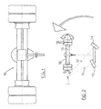
- An axle 10 of this type is schematically illustrated in figure 1 .
- FIG. 2 illustrates that the centre of rotation C of the vehicle, during steering, is given by the conjoining point of the axes 11, 12 of the steering wheels 13, 14 and that the conjoining point lies on the axis 15 of the axle 10, in any case in an external position thereto.
- the configuration illustrated in the figure might well correspond to the minimum steering radius obtainable. This means that the steering space cannot be less than a limit constituted by the circumference having the centre positioned in the centre of rotation C denoted in figure 2 and a radius equal to the distance of the external pair of wheels 16, from the centre of rotation.
- the main aim of the present invention is to provide a traction axle for self-propelling work machines which enables the aforesaid machines to steer in very modest spaces and exhibits, at the same time, a structural configuration having a limited complexity.
- a further aim of the invention is to provide a traction axle for work machines destined to move containers in port areas or the like, and/or in general for moving heavy loads, which enables obtaining minimum steering spaces and which can be manufactured in an industrially economical way.
- a traction axle in particular for self-propelling work machines destined for moving containers, comprising a differential arranged centrally on the axle, wherein a second differential works in combination with the first above-mentioned differential in such a way as to cause same-direction or opposite rotation of the two semi-axles of the axle according to whether the traction drive reaches in input to said first or said second differential.
- the second differential comprises its own semiaxles arranged parallel to the semiaxles of the traction axle of the invention, a first semi-axle of the second differential being connected to the corresponding semi-axle of the traction axle of by means of a first pair of cogwheels, a second semi-axle of the second differential being connected to the corresponding semi-axle of the traction axle by means of a second pair of cogwheels, a further cogwheel, free to rotate, being interposed between the wheels of said second pair of wheels.
- the input drive to the differential arranged centrally on the axle of the invention comes from the traction motor of the work machine; the drive in input to the second differential advantageously comes from an auxiliary hydraulic or electric motor, having sufficient power to enable rotation of the work machine, or it comes from the traction motor via a gearbox which alternatively connects said motor to said main differential or to said second differential.
- the two wheels of the axle rotate in the opposite direction to one another, so the centre of rotation of the vehicle becomes internal of the space comprised between the two wheels, the exact location thereof being a function of the steering angle required.
- the two wheels rotate at the same velocity and in opposite directions, and the centre of rotation of the vehicle coincides with the centre of the traction axle, thus obtaining the result that the vehicle can in practice rotate on itself, about the vertical axis passing through the main differential.
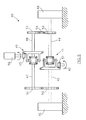
- axle 40 denotes in its entirety a traction axle, in particular for large and high-performance self-propelled work machines.
- the axle 40 comprises a first differential 41 which is reached by the drive 42 generated by the traction motor of the work machine, and from which two semi-axles 43, 44 branch off towards the two drive wheels 45, 46.
- the two semiaxes 43, 44 are respectively coupled in rotation with further two semiaxes 47, 48, exiting from a second differential 49, arranged parallel to the first differential 41; the coupling between the two semiaxes 43, 47, located on a side of the two differentials, is achieved by a simple pair of cogwheels 50, 51, solidly constrained respectively to the semi-axle 43 and the semi-axle 47, while the coupling between the other two semiaxes 44, 48, located on the other side of the differentials, takes place by means of the use of three cogwheels 52, 53, 54, two of which, 52, 54 are solidly constrained respectively to the semi-axle 44 and the semi-axle 48, and the other cogwheel 54 is interposed, freely rotatingly, between said two cogwheels 52, 53.
- this difference in velocity is nil and the centre of rotation of the vehicle coincides with the vertical axis passing through the centre of the axle.
- the centre of rotation distances from the above-mentioned vertical axis progressively as a smaller degree of steering is requested.
- said centre of rotation comes to be positioned at one of the two wheels 45, 46, the rotation velocity of this wheel is annulled and then recommences in the opposite direction, i.e. in the same direction as the other wheel, and said centre of rotation is located externally of the space comprised between the two wheels, and has, from this point onwards, the same behaviour as the vehicles provided with a traditional axle.
- this change of activation occurs automatically according to the command on the vehicle steering, thanks to a control unit which as a function of various positioning and status signals coming from sensors associated to the vehicle wheels and/or various devices, pilots the above-mentioned gearbox in the activating of the differentials, enabling or not the drive transmission of the main and auxiliary traction motors, or intervening on a true and proper mechanical gearbox for transmission of the traction drive coming from the traction motor of the vehicle, according to the possible schematic structural configuration illustrated in figure 6 .
- the axle 40' of this embodiment of the invention is provided with a gearbox 60, interposed between the shaft of the traction motor of the vehicle and the pinions 55', 57', of the two differentials 49', 41', positioned and connected to one another according to the diagram of figure 5 .
- the function of said gearbox 60 is simply to shift the traction drive 42' from one to the other of the pinions 55', 57' of the two differentials 49', 41', which shift is advantageously controlled as a function of the degree of steering that is to be obtained.
- the gearbox 60 is automatically commanded to transmit the traction drive 42' only towards the pinion 55' of the differential 49'.
- the gearbox 60 is automatically commanded to transmit the traction drive 42' only towards the pinion 57' of the differential 41'.
- axle of the invention can obviously be applied also to self-propelling machines operating in the sectors when the logistics, i.e. optimisation of the spaces available for storing goods, have a strategic role. Modifications of a practical-applicational nature can be made to the constructional details of the variants and embodiments described above without their forsaking the scope of protection of the inventive idea as claimed herein below.
Landscapes
- Engineering & Computer Science (AREA)
- Transportation (AREA)
- Chemical & Material Sciences (AREA)
- Combustion & Propulsion (AREA)
- Mechanical Engineering (AREA)
- Structural Engineering (AREA)
- Civil Engineering (AREA)
- Life Sciences & Earth Sciences (AREA)
- Geology (AREA)
- Retarders (AREA)
- Vehicle Body Suspensions (AREA)
- Jib Cranes (AREA)
Description
- The present invention relates to a traction axle for self-propelling work machines. Document
US 5 910 060 describes a traction axle according to the preamble ofclaim 1. - In particular, the invention relates to the front traction axle of lift trucks.
- The traditional traction axle of self-propelling work machines destined for movement of goods in specific areas, such as ports or areas in general set aside for sorting containers and general goods, comprises, as is known, a differential group arranged centrally on the axle, from which the drive transmission semi-axles depart towards the two gear-reducer groups complete with brakes, which, in consideration of the high traction torques and loads in play, generally comprise two or more twinned wheels. An
axle 10 of this type is schematically illustrated infigure 1 . - As in all traditional traction axes, when the work machine steers, the two wheel groups rotate at different velocities but in the same rotating direction, and the difference in velocity between the two wheel groups is greater the smaller the steering radius required.
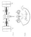
Figure 2 illustrates that the centre of rotation C of the vehicle, during steering, is given by the conjoining point of the axes 11, 12 of the steering wheels 13, 14 and that the conjoining point lies on theaxis 15 of theaxle 10, in any case in an external position thereto. The configuration illustrated in the figure might well correspond to the minimum steering radius obtainable. This means that the steering space cannot be less than a limit constituted by the circumference having the centre positioned in the centre of rotation C denoted infigure 2 and a radius equal to the distance of the external pair ofwheels 16, from the centre of rotation. - With the aim of increasing the manoeuvring capacity of these work machines, a solution has recently been introduced, object of an industrial patent in the name of the present applicant, with which the centre of rotation of the vehicle can be located in an intermediate position between the two wheels of the axle such as to allow very small radius steering spaces to be achieved. Indeed said centre of rotation C can be located in the central position of the
axle 20, coinciding with the axis of the differential, as illustrated infigure 4 , and thus enable rotation of the vehicle on itself, with a zero radius. In this situation, theaxes steering wheels wheel groups 25, 26 of theaxle 20. This is a special configuration among those obtainable by means of the structural solution substantially illustrated infigure 3 , where twodrive inverter groups semi-axles differential 21. Said two inverter groups are automatically engaged or disengaged according to the entity and direction of steering requested. When the requested steering is of a modest entity, or in any case such that the centre of rotation is external of the axle, as infigure 2 , neither of the two inverter groups is enabled and therefore the motion of the twosemiaxes respective wheels 25, 26 is in a same direction, though having different values, such as normally happens in all traditional differential groups, while when the steering requested is of such an entity that the centre of rotation of the vehicle must be internal of the axle, one or the other of the above-mentioned inverters is enabled such as to cause an inverse rotation of the wheel located internally of the curve. - A consideration however is that the practical implementation of the above-described solution is associated with a certain structural complexity of the axle due not only to the complexity of each drive inverter group but also the fact that the engaging or disengaging of the two inverter groups can occur only thanks to the use of clutch and brake groups duly interposed between the differential and the inverter groups, or also between the inverters and the respective wheel groups.
- The main aim of the present invention is to provide a traction axle for self-propelling work machines which enables the aforesaid machines to steer in very modest spaces and exhibits, at the same time, a structural configuration having a limited complexity.
- A further aim of the invention is to provide a traction axle for work machines destined to move containers in port areas or the like, and/or in general for moving heavy loads, which enables obtaining minimum steering spaces and which can be manufactured in an industrially economical way.
- The above aims and more besides will be attained by means of a traction axle, in particular for self-propelling work machines destined for moving containers, comprising a differential arranged centrally on the axle, wherein a second differential works in combination with the first above-mentioned differential in such a way as to cause same-direction or opposite rotation of the two semi-axles of the axle according to whether the traction drive reaches in input to said first or said second differential.
- The second differential comprises its own semiaxles arranged parallel to the semiaxles of the traction axle of the invention, a first semi-axle of the second differential being connected to the corresponding semi-axle of the traction axle of by means of a first pair of cogwheels, a second semi-axle of the second differential being connected to the corresponding semi-axle of the traction axle by means of a second pair of cogwheels, a further cogwheel, free to rotate, being interposed between the wheels of said second pair of wheels. The input drive to the differential arranged centrally on the axle of the invention comes from the traction motor of the work machine; the drive in input to the second differential advantageously comes from an auxiliary hydraulic or electric motor, having sufficient power to enable rotation of the work machine, or it comes from the traction motor via a gearbox which alternatively connects said motor to said main differential or to said second differential.
- In the configuration in which the drive reaches in input to the second differential instead of the main differential, the two wheels of the axle rotate in the opposite direction to one another, so the centre of rotation of the vehicle becomes internal of the space comprised between the two wheels, the exact location thereof being a function of the steering angle required. At the maximum steering angle requested, the two wheels rotate at the same velocity and in opposite directions, and the centre of rotation of the vehicle coincides with the centre of the traction axle, thus obtaining the result that the vehicle can in practice rotate on itself, about the vertical axis passing through the main differential.
- It is clear that the advantages with respect to both the traditional vehicles at present in use, and with respect to the vehicles in which the solution comprising the inverter groups on the two semiaxes of the axle is adopted, which advantages are associated on the one hand to the possibility of bringing the centre of rotation of the vehicle internally of the space comprised between the drive wheels, and on the other hand to the structural simplicity that is overall obtainable.
- Further characteristics and advantages of the present invention will more fully emerge from the detailed description that follows of a preferred, though not exclusive, embodiment, of the invention, illustrated purely by way of non-limiting example, in the accompanying further figures, in which:
-
figure 5 is a schematic plan view of a traction axle according to the invention; -
figure 6 is a further embodiment of the axle of the invention. - With reference to
figure 5 , 40 denotes in its entirety a traction axle, in particular for large and high-performance self-propelled work machines. Theaxle 40 comprises afirst differential 41 which is reached by thedrive 42 generated by the traction motor of the work machine, and from which twosemi-axles drive wheels - The two
semiaxes semiaxes second differential 49, arranged parallel to thefirst differential 41; the coupling between the twosemiaxes cogwheels semi-axle 43 and thesemi-axle 47, while the coupling between the other twosemiaxes cogwheels semi-axle 44 and thesemi-axle 48, and theother cogwheel 54 is interposed, freely rotatingly, between said twocogwheels - With this structural configuration it can be observed that, independently of the functioning mode and/or the activation of the two differentials as illustrated in the following, two of the above-mentioned
semiaxles semiaxles - It therefore follows that:
- a) in the event that no drive from the
auxiliary motor 56 or other sources reaches theinput pinion 55 of thesecond differential 49, and the pinion is kept idle, and in the further event that the traction drive arrives in input to thefirst differential 41, the drive will be transmitted to the twosemi-axles semi-axle 47 connected to thesemi-axles 43 will rotate in the opposite direction thereto, while thesemi-axle 48 drawn in rotation by the satellite and planetary gears of thedifferential 41 will rotate in the opposite direction to thesemi-axle 47 and therefore in the same direction as thesemi-axle 43 and thesemi-axle 44.
The possible different rotation velocity, in direction as well as modulus, of thesemi-axles differential 49 which is idle. - b) in the event that no drive reaches the
input pinion 57 of thefirst differential 41, and the pinion is kept idle, and in the further event that the traction drive arrives in input to thesecond differential 49, the drive is transmitted to the twosemi-axles semi-axle 43, connected to thesemi-axle 47, will rotate in the opposite direction thereto, while the semi-axle 44 drawn in rotation by the satellite and planetary gears of thedifferential 49, will rotate in the opposite direction to thesemi-axle 43 and in the same direction as thesemi-axle 47 and thesemi-axle 48. - The possible different rotation velocity, in direction as well as in modulus, of the
semi-axles differential 41, which is idle. - The result of the above is such that in the first case the
semi-axles semi-axles wheels - In the limit situation corresponding to the greater degree of steering obtainable, this difference in velocity is nil and the centre of rotation of the vehicle coincides with the vertical axis passing through the centre of the axle. The centre of rotation distances from the above-mentioned vertical axis progressively as a smaller degree of steering is requested. At the moment when, proceeding in the request for a progressively smaller steering, said centre of rotation comes to be positioned at one of the two
wheels - Note that the inversion of the rotation velocity of one of the two wheels of the axle takes place, in reference to previous points a) and b), only following the change in the activation of the two
differentials - Further note that this change of activation occurs automatically according to the command on the vehicle steering, thanks to a control unit which as a function of various positioning and status signals coming from sensors associated to the vehicle wheels and/or various devices, pilots the above-mentioned gearbox in the activating of the differentials, enabling or not the drive transmission of the main and auxiliary traction motors, or intervening on a true and proper mechanical gearbox for transmission of the traction drive coming from the traction motor of the vehicle, according to the possible schematic structural configuration illustrated in
figure 6 . - The axle 40' of this embodiment of the invention is provided with a
gearbox 60, interposed between the shaft of the traction motor of the vehicle and the pinions 55', 57', of the two differentials 49', 41', positioned and connected to one another according to the diagram offigure 5 . - The function of said
gearbox 60 is simply to shift the traction drive 42' from one to the other of the pinions 55', 57' of the two differentials 49', 41', which shift is advantageously controlled as a function of the degree of steering that is to be obtained. When a minimum-radius steering is requested, i.e. for which the centre of rotation of the vehicle has to be positioned internally of the two wheels 45', 46' of the vehicle, thegearbox 60 is automatically commanded to transmit the traction drive 42' only towards the pinion 55' of the differential 49'. When, on the other hand, the steering requested is of a smaller entity, so that the centre of rotation of the vehicle is positioned externally of the base perimeter of the vehicle, thegearbox 60 is automatically commanded to transmit the traction drive 42' only towards the pinion 57' of the differential 41'. - Further solutions can certainly be provided, as well as structural configurations comprising various devices that can equally enable activation of one or the other differential, and, consequently, the positioning of the centre of rotation C of the vehicle internally of the axle in automatic mode according to the degree of steering requested.
- As well as self-propelling work machines destined to move containers in port areas, the axle of the invention can obviously be applied also to self-propelling machines operating in the sectors when the logistics, i.e. optimisation of the spaces available for storing goods, have a strategic role. Modifications of a practical-applicational nature can be made to the constructional details of the variants and embodiments described above without their forsaking the scope of protection of the inventive idea as claimed herein below.
Claims (8)
- A traction axle, in particular for self-propelling work machines, said self-propelling work machines comprising, additionally to said traction axle, idle steering or directing wheels activated by a steering command, where by it comprises a first differential (41) connected by means of two semi-axles (43, 44) to wheels (45, 46) of the work machine and a second differential (49) operating in combination with said first differential (41) such as to obtain an equal or opposite rotation of said semi-axles (43, 44) according to whether the traction motion of the machine is in input to said first differential (41) or to said second differential (49), giving rise to a change of activation, characterised in that this change occurs automatically according to the command on the vehicle steering, due to a control unit acting according to various positioning and status signals in arrival from sensors associated to the vehicle wheels.
- The traction axle (40) according to the preceding claim, characterised in that the said control unit acts according to various positioning and status signals in arrival from sensors associated to the vehicle wheels piloting the aforesaid change in activation of the differentials, enabling or not the transmission of drive of main and auxiliary traction motors.
- The traction axle (40) according to the preceding claim, characterised in that said second differential (49) is connected to two further semi-axles (47, 48) arranged parallel to said semi-axles (43, 44) connected to the wheels (45, 46) of the work machine, a first semi-axle (47) of said further semi-axles (47, 48) being connected to the corresponding semi-axle (43) connected to the wheel (45) of the machine by means of a first pair of gears (50, 51), a second semi-axle (48) of said further semi-axles (47, 48) being connected to the corresponding semi-axle (44) connected to the other wheel (46) of the machine by means of a second pair of gears (52, 53), a freely rotating further gear (54) being interposed between the gears of said second pair of gears.
- The traction axle (40) according to the preceding claim, characterised in that the drive in input to said first differential (41) originates from the traction motor of the work machine and the drive in input to said second differential (49) originates from an auxiliary motor (56).
- The traction axle (40) according to the preceding claim, characterised in that the transmission of the drive in input to said first differential (41) takes place alternatively to the transmission of the motion in input to said second differential (49).
- The traction axle (40') according to claim 1, characterised in that it comprises a gearbox (60) interposed between the shaft of the traction motor of the work machine and the pinions (55', 57') of said differentials (41', 49'), said gearbox (60) being suitable for switching the traction motion (42') from one of said pinions (55', 57') to the other.
- The traction axle (40') according to the preceding claim, characterised in that the said control unit acts according to various positioning and status signals in arrival from sensors associated to the vehicle wheels and piloting the aforesaid change in activation of the differential, by intervening on said mechanical transmission gearbox of the traction drive originating from the vehicle traction motor.
- The traction axle (40') according to the preceding claim, characterised in that said gearbox (60) is commanded to automatically switch the traction motion from one of said differentials (41', 49') to the other, according to a steering angle requested for the work machine.
Applications Claiming Priority (1)
| Application Number | Priority Date | Filing Date | Title |
|---|---|---|---|
| IT000232A ITMO20110232A1 (en) | 2011-09-15 | 2011-09-15 | PERFECTED TRACTION AXLE FOR OPERATING MACHINES. |
Publications (2)
| Publication Number | Publication Date |
|---|---|
| EP2570332A1 EP2570332A1 (en) | 2013-03-20 |
| EP2570332B1 true EP2570332B1 (en) | 2014-07-16 |
Family
ID=45491688
Family Applications (1)
| Application Number | Title | Priority Date | Filing Date |
|---|---|---|---|
| EP12179090.1A Active EP2570332B1 (en) | 2011-09-15 | 2012-08-02 | An improved traction axle for work machines |
Country Status (2)
| Country | Link |
|---|---|
| EP (1) | EP2570332B1 (en) |
| IT (1) | ITMO20110232A1 (en) |
Families Citing this family (2)
| Publication number | Priority date | Publication date | Assignee | Title |
|---|---|---|---|---|
| DE102017203666A1 (en) * | 2017-03-07 | 2018-09-13 | Robert Bosch Gmbh | A steering apparatus for a vehicle and method for steering a vehicle |
| CN118757552A (en) * | 2024-07-23 | 2024-10-11 | 席忠 | Active split differential and automobile |
Family Cites Families (8)
| Publication number | Priority date | Publication date | Assignee | Title |
|---|---|---|---|---|
| BE404549A (en) * | 1934-02-05 | |||
| US2542157A (en) * | 1948-09-22 | 1951-02-20 | Robert L Odom | Gearing for steering two-wheel or two-track driven machines |
| US4776236A (en) * | 1983-10-21 | 1988-10-11 | Gleasman Vernon E | No-slip, imposed differential |
| US4882947A (en) * | 1986-01-29 | 1989-11-28 | Barnard Jan H | Track-laying device |
| GB9514213D0 (en) * | 1995-07-12 | 1995-09-13 | Secr Defence | Steering system for skid steer vehicles |
| US5910060A (en) * | 1998-03-05 | 1999-06-08 | Blume; David B. | Transmission |
| US6540633B1 (en) * | 1998-09-25 | 2003-04-01 | Tuff Torq Corporation | Transmission for speed changing and steering of a vehicle |
| US6257357B1 (en) * | 1999-03-26 | 2001-07-10 | Deere & Company | Steering device for drive and steer transmission |
-
2011
- 2011-09-15 IT IT000232A patent/ITMO20110232A1/en unknown
-
2012
- 2012-08-02 EP EP12179090.1A patent/EP2570332B1/en active Active
Also Published As
| Publication number | Publication date |
|---|---|
| ITMO20110232A1 (en) | 2013-03-16 |
| EP2570332A1 (en) | 2013-03-20 |
Similar Documents
| Publication | Publication Date | Title |
|---|---|---|
| US9221334B2 (en) | Drive train of a solely electrically driven motor vehicle having two electric motors | |
| CN101293532B (en) | Variable gear ratio steering apparatus | |
| US20120089310A1 (en) | Two/four-wheel drive mode shift controller for traction-transmitting part time four-wheel drive vehicle and method for controlling the same | |
| JP2010023809A (en) | Actuator for driving vehicle | |
| EP1238890A1 (en) | Crawler vehicle transmission-steering assembly. | |
| JP2011133110A (en) | Right and left wheel drive gear, front and rear wheel drive gear, and method for controlling the same | |
| JP2010185486A (en) | Drive unit for vehicle | |
| EP2570332A1 (en) | An improved traction axle for work machines | |
| JP4715508B2 (en) | Left / right driving force distribution device | |
| CA2785700C (en) | Steering drive system and skid steer vehicle equipped therewith | |
| JP4759946B2 (en) | Left and right wheel drive device, front and rear wheel drive device and control method thereof | |
| JP2014132196A (en) | Change speed gear of working vehicle | |
| JP2014051998A (en) | Driving apparatus for vehicle | |
| KR101467058B1 (en) | Transmission apparatus preventing a torque drop during shifting | |
| JP4474842B2 (en) | Work vehicle | |
| JP6064459B2 (en) | Vehicle drive device | |
| JP6194399B1 (en) | Power equipment | |
| KR101731871B1 (en) | Working Vehicle Cruise Control System Having High Efficiency | |
| JP2019143733A (en) | Vehicular drive device | |
| CN102267380B (en) | Doubling transmission device of crawler tractor | |
| JP4933387B2 (en) | Tractor | |
| JP3640281B2 (en) | Crawler type work vehicle travel drive device | |
| JP7452457B2 (en) | power transmission device | |
| JP2013170588A (en) | Transaxle and wheel type work vehicle | |
| US9429212B2 (en) | Axle device for working machines with at least one axle center transmission |
Legal Events
| Date | Code | Title | Description |
|---|---|---|---|
| PUAI | Public reference made under article 153(3) epc to a published international application that has entered the european phase |
Free format text: ORIGINAL CODE: 0009012 |
|
| 17P | Request for examination filed |
Effective date: 20121213 |
|
| AK | Designated contracting states |
Kind code of ref document: A1 Designated state(s): AL AT BE BG CH CY CZ DE DK EE ES FI FR GB GR HR HU IE IS IT LI LT LU LV MC MK MT NL NO PL PT RO RS SE SI SK SM TR |
|
| AX | Request for extension of the european patent |
Extension state: BA ME |
|
| RIC1 | Information provided on ipc code assigned before grant |
Ipc: B66F 9/075 20060101ALI20130614BHEP Ipc: B62D 11/10 20060101ALI20130614BHEP Ipc: B62D 11/04 20060101AFI20130614BHEP |
|
| GRAP | Despatch of communication of intention to grant a patent |
Free format text: ORIGINAL CODE: EPIDOSNIGR1 |
|
| INTG | Intention to grant announced |
Effective date: 20140416 |
|
| GRAS | Grant fee paid |
Free format text: ORIGINAL CODE: EPIDOSNIGR3 |
|
| GRAA | (expected) grant |
Free format text: ORIGINAL CODE: 0009210 |
|
| AK | Designated contracting states |
Kind code of ref document: B1 Designated state(s): AL AT BE BG CH CY CZ DE DK EE ES FI FR GB GR HR HU IE IS IT LI LT LU LV MC MK MT NL NO PL PT RO RS SE SI SK SM TR |
|
| AX | Request for extension of the european patent |
Extension state: BA ME |
|
| RAP1 | Party data changed (applicant data changed or rights of an application transferred) |
Owner name: FIVES OTO S.P.A. |
|
| REG | Reference to a national code |
Ref country code: GB Ref legal event code: FG4D |
|
| REG | Reference to a national code |
Ref country code: CH Ref legal event code: EP |
|
| REG | Reference to a national code |
Ref country code: IE Ref legal event code: FG4D |
|
| REG | Reference to a national code |
Ref country code: AT Ref legal event code: REF Ref document number: 677427 Country of ref document: AT Kind code of ref document: T Effective date: 20140815 |
|
| REG | Reference to a national code |
Ref country code: DE Ref legal event code: R096 Ref document number: 602012002423 Country of ref document: DE Effective date: 20140904 |
|
| REG | Reference to a national code |
Ref country code: SE Ref legal event code: TRGR |
|
| REG | Reference to a national code |
Ref country code: NL Ref legal event code: VDEP Effective date: 20140716 |
|
| REG | Reference to a national code |
Ref country code: AT Ref legal event code: MK05 Ref document number: 677427 Country of ref document: AT Kind code of ref document: T Effective date: 20140716 |
|
| REG | Reference to a national code |
Ref country code: LT Ref legal event code: MG4D |
|
| PG25 | Lapsed in a contracting state [announced via postgrant information from national office to epo] |
Ref country code: ES Free format text: LAPSE BECAUSE OF FAILURE TO SUBMIT A TRANSLATION OF THE DESCRIPTION OR TO PAY THE FEE WITHIN THE PRESCRIBED TIME-LIMIT Effective date: 20140716 Ref country code: FI Free format text: LAPSE BECAUSE OF FAILURE TO SUBMIT A TRANSLATION OF THE DESCRIPTION OR TO PAY THE FEE WITHIN THE PRESCRIBED TIME-LIMIT Effective date: 20140716 Ref country code: GR Free format text: LAPSE BECAUSE OF FAILURE TO SUBMIT A TRANSLATION OF THE DESCRIPTION OR TO PAY THE FEE WITHIN THE PRESCRIBED TIME-LIMIT Effective date: 20141017 Ref country code: NO Free format text: LAPSE BECAUSE OF FAILURE TO SUBMIT A TRANSLATION OF THE DESCRIPTION OR TO PAY THE FEE WITHIN THE PRESCRIBED TIME-LIMIT Effective date: 20141016 Ref country code: BG Free format text: LAPSE BECAUSE OF FAILURE TO SUBMIT A TRANSLATION OF THE DESCRIPTION OR TO PAY THE FEE WITHIN THE PRESCRIBED TIME-LIMIT Effective date: 20141016 Ref country code: LT Free format text: LAPSE BECAUSE OF FAILURE TO SUBMIT A TRANSLATION OF THE DESCRIPTION OR TO PAY THE FEE WITHIN THE PRESCRIBED TIME-LIMIT Effective date: 20140716 Ref country code: PT Free format text: LAPSE BECAUSE OF FAILURE TO SUBMIT A TRANSLATION OF THE DESCRIPTION OR TO PAY THE FEE WITHIN THE PRESCRIBED TIME-LIMIT Effective date: 20141117 |
|
| PG25 | Lapsed in a contracting state [announced via postgrant information from national office to epo] |
Ref country code: AT Free format text: LAPSE BECAUSE OF FAILURE TO SUBMIT A TRANSLATION OF THE DESCRIPTION OR TO PAY THE FEE WITHIN THE PRESCRIBED TIME-LIMIT Effective date: 20140716 Ref country code: IS Free format text: LAPSE BECAUSE OF FAILURE TO SUBMIT A TRANSLATION OF THE DESCRIPTION OR TO PAY THE FEE WITHIN THE PRESCRIBED TIME-LIMIT Effective date: 20141116 Ref country code: CY Free format text: LAPSE BECAUSE OF FAILURE TO SUBMIT A TRANSLATION OF THE DESCRIPTION OR TO PAY THE FEE WITHIN THE PRESCRIBED TIME-LIMIT Effective date: 20140716 Ref country code: NL Free format text: LAPSE BECAUSE OF FAILURE TO SUBMIT A TRANSLATION OF THE DESCRIPTION OR TO PAY THE FEE WITHIN THE PRESCRIBED TIME-LIMIT Effective date: 20140716 Ref country code: PL Free format text: LAPSE BECAUSE OF FAILURE TO SUBMIT A TRANSLATION OF THE DESCRIPTION OR TO PAY THE FEE WITHIN THE PRESCRIBED TIME-LIMIT Effective date: 20140716 Ref country code: LV Free format text: LAPSE BECAUSE OF FAILURE TO SUBMIT A TRANSLATION OF THE DESCRIPTION OR TO PAY THE FEE WITHIN THE PRESCRIBED TIME-LIMIT Effective date: 20140716 Ref country code: RS Free format text: LAPSE BECAUSE OF FAILURE TO SUBMIT A TRANSLATION OF THE DESCRIPTION OR TO PAY THE FEE WITHIN THE PRESCRIBED TIME-LIMIT Effective date: 20140716 |
|
| REG | Reference to a national code |
Ref country code: DE Ref legal event code: R097 Ref document number: 602012002423 Country of ref document: DE |
|
| PG25 | Lapsed in a contracting state [announced via postgrant information from national office to epo] |
Ref country code: EE Free format text: LAPSE BECAUSE OF FAILURE TO SUBMIT A TRANSLATION OF THE DESCRIPTION OR TO PAY THE FEE WITHIN THE PRESCRIBED TIME-LIMIT Effective date: 20140716 Ref country code: CZ Free format text: LAPSE BECAUSE OF FAILURE TO SUBMIT A TRANSLATION OF THE DESCRIPTION OR TO PAY THE FEE WITHIN THE PRESCRIBED TIME-LIMIT Effective date: 20140716 Ref country code: MC Free format text: LAPSE BECAUSE OF FAILURE TO SUBMIT A TRANSLATION OF THE DESCRIPTION OR TO PAY THE FEE WITHIN THE PRESCRIBED TIME-LIMIT Effective date: 20140716 Ref country code: DK Free format text: LAPSE BECAUSE OF FAILURE TO SUBMIT A TRANSLATION OF THE DESCRIPTION OR TO PAY THE FEE WITHIN THE PRESCRIBED TIME-LIMIT Effective date: 20140716 Ref country code: BE Free format text: LAPSE BECAUSE OF NON-PAYMENT OF DUE FEES Effective date: 20140831 Ref country code: SK Free format text: LAPSE BECAUSE OF FAILURE TO SUBMIT A TRANSLATION OF THE DESCRIPTION OR TO PAY THE FEE WITHIN THE PRESCRIBED TIME-LIMIT Effective date: 20140716 Ref country code: RO Free format text: LAPSE BECAUSE OF FAILURE TO SUBMIT A TRANSLATION OF THE DESCRIPTION OR TO PAY THE FEE WITHIN THE PRESCRIBED TIME-LIMIT Effective date: 20140716 |
|
| REG | Reference to a national code |
Ref country code: IE Ref legal event code: MM4A |
|
| PLBE | No opposition filed within time limit |
Free format text: ORIGINAL CODE: 0009261 |
|
| STAA | Information on the status of an ep patent application or granted ep patent |
Free format text: STATUS: NO OPPOSITION FILED WITHIN TIME LIMIT |
|
| 26N | No opposition filed |
Effective date: 20150417 |
|
| PG25 | Lapsed in a contracting state [announced via postgrant information from national office to epo] |
Ref country code: IE Free format text: LAPSE BECAUSE OF NON-PAYMENT OF DUE FEES Effective date: 20140802 |
|
| REG | Reference to a national code |
Ref country code: FR Ref legal event code: PLFP Year of fee payment: 4 |
|
| PG25 | Lapsed in a contracting state [announced via postgrant information from national office to epo] |
Ref country code: SI Free format text: LAPSE BECAUSE OF FAILURE TO SUBMIT A TRANSLATION OF THE DESCRIPTION OR TO PAY THE FEE WITHIN THE PRESCRIBED TIME-LIMIT Effective date: 20140716 |
|
| REG | Reference to a national code |
Ref country code: CH Ref legal event code: PL |
|
| PG25 | Lapsed in a contracting state [announced via postgrant information from national office to epo] |
Ref country code: CH Free format text: LAPSE BECAUSE OF NON-PAYMENT OF DUE FEES Effective date: 20150831 Ref country code: LI Free format text: LAPSE BECAUSE OF NON-PAYMENT OF DUE FEES Effective date: 20150831 |
|
| PG25 | Lapsed in a contracting state [announced via postgrant information from national office to epo] |
Ref country code: SM Free format text: LAPSE BECAUSE OF FAILURE TO SUBMIT A TRANSLATION OF THE DESCRIPTION OR TO PAY THE FEE WITHIN THE PRESCRIBED TIME-LIMIT Effective date: 20140716 |
|
| PG25 | Lapsed in a contracting state [announced via postgrant information from national office to epo] |
Ref country code: MT Free format text: LAPSE BECAUSE OF FAILURE TO SUBMIT A TRANSLATION OF THE DESCRIPTION OR TO PAY THE FEE WITHIN THE PRESCRIBED TIME-LIMIT Effective date: 20140716 |
|
| PG25 | Lapsed in a contracting state [announced via postgrant information from national office to epo] |
Ref country code: TR Free format text: LAPSE BECAUSE OF FAILURE TO SUBMIT A TRANSLATION OF THE DESCRIPTION OR TO PAY THE FEE WITHIN THE PRESCRIBED TIME-LIMIT Effective date: 20140716 Ref country code: HR Free format text: LAPSE BECAUSE OF FAILURE TO SUBMIT A TRANSLATION OF THE DESCRIPTION OR TO PAY THE FEE WITHIN THE PRESCRIBED TIME-LIMIT Effective date: 20140716 Ref country code: LU Free format text: LAPSE BECAUSE OF NON-PAYMENT OF DUE FEES Effective date: 20140802 Ref country code: HU Free format text: LAPSE BECAUSE OF FAILURE TO SUBMIT A TRANSLATION OF THE DESCRIPTION OR TO PAY THE FEE WITHIN THE PRESCRIBED TIME-LIMIT; INVALID AB INITIO Effective date: 20120802 Ref country code: BE Free format text: LAPSE BECAUSE OF FAILURE TO SUBMIT A TRANSLATION OF THE DESCRIPTION OR TO PAY THE FEE WITHIN THE PRESCRIBED TIME-LIMIT Effective date: 20140716 |
|
| REG | Reference to a national code |
Ref country code: FR Ref legal event code: PLFP Year of fee payment: 5 |
|
| REG | Reference to a national code |
Ref country code: FR Ref legal event code: PLFP Year of fee payment: 6 |
|
| PG25 | Lapsed in a contracting state [announced via postgrant information from national office to epo] |
Ref country code: MK Free format text: LAPSE BECAUSE OF FAILURE TO SUBMIT A TRANSLATION OF THE DESCRIPTION OR TO PAY THE FEE WITHIN THE PRESCRIBED TIME-LIMIT Effective date: 20140716 |
|
| REG | Reference to a national code |
Ref country code: FR Ref legal event code: PLFP Year of fee payment: 7 |
|
| PG25 | Lapsed in a contracting state [announced via postgrant information from national office to epo] |
Ref country code: AL Free format text: LAPSE BECAUSE OF FAILURE TO SUBMIT A TRANSLATION OF THE DESCRIPTION OR TO PAY THE FEE WITHIN THE PRESCRIBED TIME-LIMIT Effective date: 20140716 |
|
| PGFP | Annual fee paid to national office [announced via postgrant information from national office to epo] |
Ref country code: FR Payment date: 20180829 Year of fee payment: 7 Ref country code: IT Payment date: 20180809 Year of fee payment: 7 |
|
| PGFP | Annual fee paid to national office [announced via postgrant information from national office to epo] |
Ref country code: GB Payment date: 20180831 Year of fee payment: 7 Ref country code: SE Payment date: 20180827 Year of fee payment: 7 |
|
| PGFP | Annual fee paid to national office [announced via postgrant information from national office to epo] |
Ref country code: DE Payment date: 20181031 Year of fee payment: 7 |
|
| REG | Reference to a national code |
Ref country code: DE Ref legal event code: R119 Ref document number: 602012002423 Country of ref document: DE |
|
| REG | Reference to a national code |
Ref country code: SE Ref legal event code: EUG |
|
| GBPC | Gb: european patent ceased through non-payment of renewal fee |
Effective date: 20190802 |
|
| PG25 | Lapsed in a contracting state [announced via postgrant information from national office to epo] |
Ref country code: SE Free format text: LAPSE BECAUSE OF NON-PAYMENT OF DUE FEES Effective date: 20190803 |
|
| PG25 | Lapsed in a contracting state [announced via postgrant information from national office to epo] |
Ref country code: DE Free format text: LAPSE BECAUSE OF NON-PAYMENT OF DUE FEES Effective date: 20200303 Ref country code: FR Free format text: LAPSE BECAUSE OF NON-PAYMENT OF DUE FEES Effective date: 20190831 |
|
| PG25 | Lapsed in a contracting state [announced via postgrant information from national office to epo] |
Ref country code: IT Free format text: LAPSE BECAUSE OF NON-PAYMENT OF DUE FEES Effective date: 20190802 Ref country code: GB Free format text: LAPSE BECAUSE OF NON-PAYMENT OF DUE FEES Effective date: 20190802 |