EP2570323A2 - Seat bank transport device - Google Patents
Seat bank transport device Download PDFInfo
- Publication number
- EP2570323A2 EP2570323A2 EP12184256A EP12184256A EP2570323A2 EP 2570323 A2 EP2570323 A2 EP 2570323A2 EP 12184256 A EP12184256 A EP 12184256A EP 12184256 A EP12184256 A EP 12184256A EP 2570323 A2 EP2570323 A2 EP 2570323A2
- Authority
- EP
- European Patent Office
- Prior art keywords
- transport device
- seat
- seat bank
- retaining rails
- bank transport
- Prior art date
- Legal status (The legal status is an assumption and is not a legal conclusion. Google has not performed a legal analysis and makes no representation as to the accuracy of the status listed.)
- Granted
Links
Images





Classifications
-
- B—PERFORMING OPERATIONS; TRANSPORTING
- B62—LAND VEHICLES FOR TRAVELLING OTHERWISE THAN ON RAILS
- B62B—HAND-PROPELLED VEHICLES, e.g. HAND CARTS OR PERAMBULATORS; SLEDGES
- B62B3/00—Hand carts having more than one axis carrying transport wheels; Steering devices therefor; Equipment therefor
- B62B3/02—Hand carts having more than one axis carrying transport wheels; Steering devices therefor; Equipment therefor involving parts being adjustable, collapsible, attachable, detachable or convertible
-
- B—PERFORMING OPERATIONS; TRANSPORTING
- B62—LAND VEHICLES FOR TRAVELLING OTHERWISE THAN ON RAILS
- B62B—HAND-PROPELLED VEHICLES, e.g. HAND CARTS OR PERAMBULATORS; SLEDGES
- B62B3/00—Hand carts having more than one axis carrying transport wheels; Steering devices therefor; Equipment therefor
- B62B3/04—Hand carts having more than one axis carrying transport wheels; Steering devices therefor; Equipment therefor involving means for grappling or securing in place objects to be carried; Loading or unloading equipment
-
- B—PERFORMING OPERATIONS; TRANSPORTING
- B62—LAND VEHICLES FOR TRAVELLING OTHERWISE THAN ON RAILS
- B62B—HAND-PROPELLED VEHICLES, e.g. HAND CARTS OR PERAMBULATORS; SLEDGES
- B62B3/00—Hand carts having more than one axis carrying transport wheels; Steering devices therefor; Equipment therefor
- B62B3/14—Hand carts having more than one axis carrying transport wheels; Steering devices therefor; Equipment therefor characterised by provisions for nesting or stacking, e.g. shopping trolleys
- B62B3/16—Hand carts having more than one axis carrying transport wheels; Steering devices therefor; Equipment therefor characterised by provisions for nesting or stacking, e.g. shopping trolleys vertically stackable
-
- B—PERFORMING OPERATIONS; TRANSPORTING
- B64—AIRCRAFT; AVIATION; COSMONAUTICS
- B64F—GROUND OR AIRCRAFT-CARRIER-DECK INSTALLATIONS SPECIALLY ADAPTED FOR USE IN CONNECTION WITH AIRCRAFT; DESIGNING, MANUFACTURING, ASSEMBLING, CLEANING, MAINTAINING OR REPAIRING AIRCRAFT, NOT OTHERWISE PROVIDED FOR; HANDLING, TRANSPORTING, TESTING OR INSPECTING AIRCRAFT COMPONENTS, NOT OTHERWISE PROVIDED FOR
- B64F5/00—Designing, manufacturing, assembling, cleaning, maintaining or repairing aircraft, not otherwise provided for; Handling, transporting, testing or inspecting aircraft components, not otherwise provided for
- B64F5/50—Handling or transporting aircraft components
-
- B—PERFORMING OPERATIONS; TRANSPORTING
- B62—LAND VEHICLES FOR TRAVELLING OTHERWISE THAN ON RAILS
- B62B—HAND-PROPELLED VEHICLES, e.g. HAND CARTS OR PERAMBULATORS; SLEDGES
- B62B2202/00—Indexing codes relating to type or characteristics of transported articles
- B62B2202/30—Furniture
- B62B2202/32—Chairs
-
- B—PERFORMING OPERATIONS; TRANSPORTING
- B62—LAND VEHICLES FOR TRAVELLING OTHERWISE THAN ON RAILS
- B62B—HAND-PROPELLED VEHICLES, e.g. HAND CARTS OR PERAMBULATORS; SLEDGES
- B62B2203/00—Grasping, holding, supporting the objects
- B62B2203/44—Clamping or supporting circumferentially
-
- B—PERFORMING OPERATIONS; TRANSPORTING
- B62—LAND VEHICLES FOR TRAVELLING OTHERWISE THAN ON RAILS
- B62B—HAND-PROPELLED VEHICLES, e.g. HAND CARTS OR PERAMBULATORS; SLEDGES
- B62B2206/00—Adjustable or convertible hand-propelled vehicles or sledges
- B62B2206/02—Adjustable or convertible hand-propelled vehicles or sledges adjustable in length or width
-
- B—PERFORMING OPERATIONS; TRANSPORTING
- B62—LAND VEHICLES FOR TRAVELLING OTHERWISE THAN ON RAILS
- B62B—HAND-PROPELLED VEHICLES, e.g. HAND CARTS OR PERAMBULATORS; SLEDGES
- B62B3/00—Hand carts having more than one axis carrying transport wheels; Steering devices therefor; Equipment therefor
- B62B3/10—Hand carts having more than one axis carrying transport wheels; Steering devices therefor; Equipment therefor characterised by supports specially adapted to objects of definite shape
Definitions
- the invention relates to a seat bank transport device for transporting a seat bank for a transport vehicle as described in the preamble of claim 1.
- FIG. 1 A conventional outside device for transporting a seat bank to the aircraft is shown in figure 1 .
- This outside device 1 for transporting a seat bank 2 comprises a pallet 8 that is movable on caster pairs 4, 6, and on which a plurality of seat rail pairs is mounted securely in the transverse position.
- Each seat rail pair includes two seat rails 10a, 10b, arranged parallel to one another, which correspond to a distance between the rails in the aircraft. In this way, a large number of different seat banks 2 can be transported with the outside device 1.
- the seat bank 2 shown comprises three seats 12, 14, 16 with a shared seat support beam 18, whose seat bank feet for example can only be accommodated in one of the seat rail pairs 10a, 10b.
- seat bank feet 20, 22 are inserted into seat rails 10a, 10b transversely relative to pallet 8 and then secured in place via a locking mechanism, which is not shown.
- the locking mechanism is released and seat bank 2 is slid out of seat rails 10a, 10b transversely relative to pallet 8.
- the object of the invention is to produce a seat bank transport device that eliminates the disadvantages described in the preceding and enables transportation of seat banks having differently spaced seat bank feet.
- the seat bank transport device thus constitutes a universal transport tool for all seat banks. Since the retaining rails are open at least in sections along the lengthwise side facing the other rail, the seat banks may be deposited on the chassis without difficulty. The laborious, time-consuming activity of sliding the seat banks in the lengthwise or crosswise direction of the seat bank transport device is no longer necessary.
- each of the retaining rails has at least one locking section on the longitudinal side thereof facing away from the other rail, the seat banks are automatically secured in place when the retaining rails on the seat bank transport device are moved together, and automatically released when the retaining rails are moved apart. This also saves installation time. Moreover, the arrangement prevents the retaining rails from being damaged and/or the seat banks from becoming caught in the retaining rails.
- the seat bank transport device is also ideally suitable for use inside the vehicle, so that time-consuming reloading of the seat banks onto a second transport device is not necessary and this also reduces installation time.
- the retaining rails are preferably movable simultaneously. This enables maximum movement of the retaining rails relative to one another in a single operation, so that the seat banks may be rapidly secured and rapidly released again. Alternatively, however, the retaining rails may also be separately adjustable.
- the displacement mechanism is equipped with two threaded rods aligned in the direction of displacement, each of which is allocated to a retaining rail, and a gearwheel that is disposed between the threaded rods and meshes with them, and an actuating element for driving the gearwheel.
- This embodiment is technically simple to construct and extremely sturdy, which is to say not prone to malfunction.
- the displacement mechanism is equipped with a link disk, guide bolts on the retaining rail side for transmitting a rotating motion of the link disk to the retaining rails, and an actuating element for driving the link disk.
- This embodiment is also technically simple to construction and very sturdy.
- the spiral slots converge radially from the outside towards the inside.
- a pinion that is connected to the gearwheel or the link disk is advantageously supported on an axis of rotation of the gearwheel and is also in operative connection with the actuating element.
- the pinion is easy to mount on the axis of rotation of the gearwheel.
- the link disk may particularly have any outer contour, so that it is adaptable to the spiral slots in instances where unoccupied disk sections may be removed from the spiral slots.
- a preferred link disk is for example oval in shape.
- the actuating element may be a lever with a handle, which is attached to a segment of the gearwheel of the displacement mechanism to transmit a rotary movement of the lever to the pinion.
- the transmission enables maximum relative movement of the retaining rails towards one another for minimum rotary movement, thus enabling both the disposal of the seat banks on the seat bank transport device and the release thereof to be accomplished more quickly.
- the displacement mechanism preferably has a positioning disk, in which a plurality of arc slots is provided for guiding the handle, each of which has an arc length that corresponds to a travel distance between an open position and a closed position of the retaining rails for each seat bank rail distance. This enables the lever to be moved between a defined open or releasing position and a defined closed or locking position, which makes removal and locking of the respective seat bank considerably easier.
- Removal of the respective seat bank may be rendered simpler still if the retaining rails are spring-biased in the opening direction, so that they are able to move apart automatically.
- the arc slots may be radially offset from each other, while at the same time adjacent arc slots adjoin each other radially, and the handle is shiftable in the lengthwise direction of the lever.
- Limit stops for the lever movements are defined by the relative radial offset, which correspond uniquely to the locking positions and release positions.
- the radial interconnections between adjacent arc slots mean that adjustments for changing rail distances may be made quickly.
- the lever may be secured in the respective locking position for the retaining rails.
- Securing may be assured for example by creating at least one securing drillhole in each arc slot to accommodate a securing pin of the handle.
- each of the arc slots may be constructed with a shoulder.
- This variant enables reliable locking with a smaller number of components, since a mechanism for inserting and removing a securing pin may be dispensed with.
- a crossbar, a threaded bolt or similar may be used as the handle.
- casters on the chassis may be adjustable relative to each other in the direction of travel of the retaining rails.
- the casters are disposed on telescopic arms, which are displaceable along a base frame of the chassis.
- the seat bank transport device is furnished with caster recesses to accommodate the casters of a seat bank transport device stacked on top of it.
- a stacking capability particularly saves space when the devices are stored and enables a number of seat bank transport devices to be moved conveniently when they are not in use.
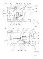
- a first embodiment of a seat bank transport device 24 is shown. This comprises a chassis 26, two retaining rails 28a, 28b and a displacement device 30 for moving retaining rails 28a, 28b in opposite directions.
- Chassis 26 comprises a base frame, which is formed by two side members 32, 34 and two cross members 36, 38 which connect side members 32, 34 to one another at the extremities thereof.
- Side members 32, 34 define a longitudinal direction x of seat bank transport device 1 and cross members 36, 38 define a transverse direction y of seat bank transport device 1.
- seat bank transport device 1 is equipped with two caster pairs 40, 42, which when view in transverse direction y comprise two casters arranged one beside the other.
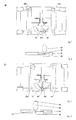
- seat bank transport device 24 In order to stack multiple seat bank transport devices 24, 24' on top of each other in vertical direction z, seat bank transport device 24 has four cup-shaped caster recesses 44 to accommodate one caster each of caster pairs 40', 42' on the upper bank transport device 24' ( figure 6 ).
- retaining rails 28a, 28b extend in transverse direction y. They are guided at their extremities in lengthwise direction x on side members 32, 34 and are displaceable in longitudinal direction x of seat bank transport device 24 from a position of small separation ( figure 2 ) to a position of large separation ( figure 3 ) relative to one another and back. Retaining rails 28a, 28b are preferably spring-biased in the opening direction. The longitudinal side of each that faces the other is of open design and the longitudinal side of each that faces away from the other is closed.
- each has a hook-like profile with a sliding portion 46 that is movable along side member 32, 34 and a locking portion 48 that extends at an angle and away from side members 32, 34.
- Locking portions 48 serve to hook around a portion of the seat bank feet to secure the seat banks in lengthwise direction x on seat bank transport device 24.
- opposite sections of retaining rails 28a, 28b each have two for example weblike limiters 50, 52 at a distance from one another in transverse direction y, as indicated by the numbered elements in figure 2 , and these limiters define a seating space 54 for inserting a seat bank foot.
- displacement mechanism 30 has a cross member 56, a gear assembly and a positioning system.
- Cross member 56 extends in transverse direction y and the end sections thereof are connected to the middle of side members 32, 34 as illustrated in figure 3 .
- This cross member serves particularly to support the gear assembly.
- it has an axis of rotation drillhole 58 designed to define an axis of rotation for a gearwheel 60 and a pinion 62 of the gear assembly, and a pivot axis drillhole 64 designed to define a pivot axis for a toothed segment 66 of the gear assembly.
- Gearwheel 60, pinion 62 and toothed segment 66 are not shown in figure 5 .
- the one end portion of cross member 56 is flared out into a positioning disk 68 to form the positioning system.
- pivot axis drillhole 64 is located in the root are of the flaring.
- the position of rotation axis drillhole 58 in cross member 56 is such that the axis of rotation and thus also gearwheel 60 and pinion 62 are positioned equidistantly between side members 32, 34.
- the axis of rotation is preferably located such that a center of gravity of the device lies on the axis of rotation when seat bank transport device 24 is in a home position.
- the gear assembly comprises two threaded rods 70, 72, gearwheel 60, pinion 62, toothed segment 66, two and one actuating element 74.
- Threaded rods 70, 72 are positioned at a distance from and parallel to one another and extend in lengthwise direction x. Each has a threaded portion and a rod portion, via which each is connected to a retaining rail 28a, 28b.
- Gearwheel 60 is supported such that it rotates about the axis of rotation that extends in vertical direction z through axis of rotation drillhole 58. It is disposed between threaded rods 70, 72 and meshes with both rods, so that when it rotates threaded rods 70, 72 are moved in opposite directions in lengthwise direction x.
- a helical spring is anchored on the axis of rotation to bias retaining rails 28a, 28b towards the open position, and one end section of this spring acts on gearwheel 60 while the other end section acts on cross member 56.
- Pinion 62 is supported on the axis of rotation of gearwheel 60 and meshes with toothed segment 66. It is permanently connected to gearwheel 60, so that a rotary motion of pinion 62 is transmitted to gearwheel 60.
- Toothed segment 66 is pivotable about the pivot axis that extends in vertical direction z. It is pivoted via actuating element 74, which is permanently disposed on an axle pin 76 of toothed segment 66 for this purpose ( figure 4 ).
- Actuating element 74 has a lever 78 that extends orthogonally to the pivot axis and a handle 80 that extends in vertical direction z.
- lever 78 or handle 80 is moved clockwise, as represented in figures 2 and 3 , retaining rails 28a, 28b are moved toward one another.
- lever 78 is moved counterclockwise, retaining rails 28a, 28b are moved apart.
- Handle 80 is movable within an elongated slot 82 extending in the longitudinal direction thereof such that it is radially displaceable when lever 78 is pivoted.
- At its foot it is equipped with a securing pin 84 that is displaceable in vertical direction z, and at its head it has a pushbutton 86 for withdrawing and inserting securing pin 84 ( figures 8 and 10 ).
- the positioning system essentially comprises positioning disk 68, which constitutes a disk segment and in which a plurality of arc slots 88a, 88b, 88c, 88d is formed, as indicated by the numbered references in figure 5 , for guiding handle 80 or a knob.
- Arc slots 88a to 88d are offset relative to each other radially in respect of the pivot axis. In this context, they are offset relative to each other in such manner that when the distance between retaining rails 28a, 28b is smallest handle 80 engages in radially innermost arc slot 88a and when the distance between retaining rails 28a, 28b is greatest it engages in radially outermost arc slot 88d ( figures 2 and 3 ).
- Arc slots 88a to 88d are positioned relative to each other in the pivot direction in such manner that each of the arc slots 88a to 88d corresponds to a seat rail distance.
- four arc slots 88a to 88d are provided and accordingly four seat bank distances may be represented.
- Each arc slot is connected at its radial limits with the respectively adjacent arc slots 88a to 88d, so that a staggered arc slot guide is formed.
- a laterally open overlap is formed between adjacent arc slots 88a to 88d, so that handle 80 is able to be moved from one of the arc slots 88a to 88d to the next arc slot 88a to 88d with a radial movement.
- Arc slots 88a to 88d have an arc length that corresponds to a travel distance of retaining rails 28a, 28b for each seat rail distance.
- Each is furnished with two limit stops 90, 92 for handle 80 at the opposite extremities thereof, limit stops 90 defining an opening or releasing position and the other limit stops 92 defining a closing or locking position of retaining rails 28a, 28b.
- a securing drillhole 94 is provided in the area of limit stops 92 at the locking extremity of each arc slot for the insertion of a securing pin 84.
- a seat bank is to be secured in position on seat bank transport device 24.
- the preselected separation between retaining rails 28a, 28b is set according to the seat bank that is to be locked by appropriate positioning of handle 80, in the example of the figure in third arc slot 88c.
- securing pin 84 of handle 80 is retracted from securing drillhole 94, and retaining rails 28a, 28b are forced apart, in the opening direction, under the spring bias of the helical spring.
- lever 78 is turned counterclockwise and handle 80 is moved to the left until it comes to rest against release end limit stop 90.
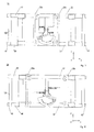
- caster pairs 40, 42 are movable in lengthwise direction x relative to each other, as shown in figures 11, 12 and 13 .
- Caster pairs 40, 42 are each supported on two telescopic arms 96, 98, which are connected with one another via one transverse arm 100 for each.
- Telescopic arms 96, 98 extend through openings in the frontal faces of side members 32, 34, and are displaceable in lengthwise direction x inside these members.
- caster pairs 40, 42 may be moved regardless of the position of retaining rails 28a, 28b. Accordingly, there is no operative connection between displacement mechanism 30 for retaining rails 28a, 28b and telescopic arms 96, 98. As is shown in figure 13 , caster pairs 40, 42 may also be moved individually, and for example the caster pair 42 on the right in figure 13 may be extended on its own.
- a second embodiment of the seat bank transport device 24 of the invention is depicted in the plan views of figures 14 and 15 and the detail view of figure 16 .
- the second embodiment is furnished with five arc slots 88a to 88e, so that five different seat bank distances may be reflected.
- arc slots 88a to 88e are set apart from each other radially and thus also laterally, and they are joined to each other via a connecting radial slot 102.
- Arc slots 88a to 88e are each prolonged beyond connecting radial slot 102, thus creating blind limit stops 90, 92.
- handle 80 cannot be shifted from the opening position and the locking position in an arc slot 88a to 88e into an adjacent arc slot 88a to 88e with a radial motion, instead the handle 80 must be freed from blind limit stops 90, 92 by moving it backwards in the direction of the arc.
- a further difference from the first embodiment consists in that arc slots 88a to 88e are offset relative to each other in such manner that when the distance between retaining rails 28a, 28b is smallest handle 80 engages in the radially outermost arc slot 88a and when the distance between retaining rails 28a, 28b is greatest, handle 80 engages in the radially innermost arc slot 88e.
- a third embodiment of seat bank transport device 24 according to the invention is presented in the plan views of figures 17 and 18 and in the detail illustration of figure 19 .
- arc slot 88a for setting a minimum distance between retaining rails 28a, 28b is radially innermost
- arc slot 88e for setting a maximum distance between retaining rails 28a, 28b is radially outermost.
- a cross member 56 with a positioning disk 68 of a fourth embodiment of the seat bank transport device 24 according to the invention is shown.
- Positioning disk 68 is based on the first embodiment with four arc slots 88a to 88d, each of which is connected to the respective neighboring arc slots 88a to 88d laterally.
- L-shaped offsets are formed at the ends of the slots instead of securing drillholes 90.
- Offsets 104 are arranged at the locking ends and are conformed radially outwardly from arc slots 88a to 88d. They lead back in the opening direction with an end section for the respective arc slot 88a to 88d and their orientation is accordingly counterclockwise.
- Each end section forms the locking end limit stop 92, against which handle 80 is pressed by the force of the helical spring.
- the opening side end sections 90 are arranged radially inwards relative to arc slots 88a to 88d and are aligned to extend at an angle to arc slots 88a to 88d. In this way, inadvertent opening of retaining rails 28a, 28b is reliably prevented.
- this offset variant enables handle 80 to have the form of a threaded bolt, for example, which extends in vertical direction z and is movable along extended slot 82 of lever 78. It is not necessary to insert and remove a securing pin 84, and so a pushbutton mechanism 86 is also unnecessary.
- a fifth embodiment of the seat bank transport device 24 of the invention 24 is shown in figures 21 and 22 . Unlike the previous embodiments presented in figures 2 to 20 , this embodiment does not have a gear assembly with two threaded rods 70, 72 and a gearwheel 66 that meshes with threaded rods 70,. 72.
- This fifth embodiment has a gear assembly with a link disk 106 and two guide bolts 108, 110.
- the other elements of the device, such as the cross member 56, pinion 62, toothed segment 66, positioning disk 68, lever 78 and handle 80 are the same as in the preceding embodiments, particularly the first embodiment as shown in figures 2 to 13 with regard to positioning disk 68 with four arc slots 88a to 88d that are in lateral contact with each other.
- Link disk 106 is mounted so as to be rotatable about the axis of rotation of pinion 62, which is permanently attached to link disk 106. It has spiral slot pair that includes two spiral slots 112a, 112b, which have a curve radius that becomes smaller towards the axis of rotation when viewed in the clockwise direction, and accordingly converge radially from the outside inwards when viewed in the clockwise direction.
- their radial inner end portions 114 are located approximately on a transverse axis of link disk 106 and their radial outer end portions 116 are located on a longitudinal axis of link disk 106.
- link disk when a minimum separation between retaining rails 28a, 28b is set, link disk is oriented in transverse direction y, and when a maximum separation between retaining rails 28a, 28b is set, link disk is oriented in lengthwise direction x. Overall, the link disk is able to pivot through 270°.
- Guide bolts 108, 110 extend in vertical direction z and are individually connected to the middle of sliding portions 46 of retaining rails 28a, 28b, the opposing long sides of which are extended in a triangular form for this purpose. They extend in vertical direction z and each is movable in one of the spiral slots 112a, 112b. As is shown in figure 21 , guide bolts 108, 110 are positioned in the area of inner end sections 114 of spiral slots 112a, 112b when the minimum separation between the retaining rails is set, and, as shown in figure 22 , in the area of outer end sections 116 of spiral slots 112a, 112b when the maximum separation between the retaining rails is set.
- Link disk 106 is controlled in the same way as in the preceding embodiments.
- a rotation of handle 80 or lever 78 is transmitted to toothed segment 66 and from this to pinion 62, from where the motion is transferred to link disk 106.
- link disk 106 is rotated counterclockwise guide bolts 108, 110 are moved from the radially innermost position shown to the radially outermost position shown in figure 22 .
- guide bolts 108, 110 are secured to sliding portions 46, the rotary motion of link disk 106 is transmitted to retaining rails 28a, 28b, which then execute a sliding movement in longitudinal direction x away from one another, as a result of which the distance between them increases.
- lever 78 To move retaining rails 28a, 28b closer to one another, lever 78 must be turned in the opposite direction.
- a seat bank transport device for transporting a bank of seats for a vehicle, comprising a chassis, a retaining rail pair that is arranged on the chassis and includes two retaining rails extending parallel to one another for accommodating seat bank feet, the lengthwise sides of these rails that face one another being open at least in sections and the lengthwise sides thereof that face away from one another each having at least one locking section, and a displacement mechanism for moving the retaining rails transversely relative to one another.
Landscapes
- Engineering & Computer Science (AREA)
- Transportation (AREA)
- Chemical & Material Sciences (AREA)
- Combustion & Propulsion (AREA)
- Mechanical Engineering (AREA)
- Manufacturing & Machinery (AREA)
- Aviation & Aerospace Engineering (AREA)
- Seats For Vehicles (AREA)
Abstract
Description
- The invention relates to a seat bank transport device for transporting a seat bank for a transport vehicle as described in the preamble of claim 1.
- Seat banks for use as seating in aircraft are usually transported to the aircraft on a mobile outside device, then loaded onto a mobile inside device and moved with this inside the aircraft fuselage to their respective installation positions. A conventional outside device for transporting a seat bank to the aircraft is shown in
figure 1 . This outside device 1 for transporting a seat bank 2 comprises apallet 8 that is movable oncaster pairs seat rails seats seat support beam 18, whose seat bank feet for example can only be accommodated in one of theseat rail pairs - For transporting seat bank 2,
seat bank feet seat rails pallet 8 and then secured in place via a locking mechanism, which is not shown. In order to transfer seat bank 2 from the outside device to the inside device inside the aircraft, the locking mechanism is released and seat bank 2 is slid out ofseat rails pallet 8. - However, inserting the seat banks in the seat rails is very time-consuming. In addition, the locking mechanism regularly catches when it is opened, causing further delays. Moreover, the seat rails, seat bank feet and the locking mechanism can be damaged as a result of this catching. It is also disadvantageous that seat banks with asymmetrical seat support beams cause the device's center of gravity to shift, making the outside device more difficult to move.
- The object of the invention is to produce a seat bank transport device that eliminates the disadvantages described in the preceding and enables transportation of seat banks having differently spaced seat bank feet.
- This object is solved with a seat bank transport device having the features of patent claim 1.
- A seat bank transport device according to the invention for transporting a seat bank for a vehicle includes a chassis, a retaining rail pair disposed on the chassis, including two retaining rails that extend parallel to one another to accommodate seat bank feet, the lengthwise sides of these rails that face one another being open at least in sections and the lengthwise sides thereof that face away from one another each having at least one locking section, and a displacement mechanism for moving the retaining rails transversely relative to one another.
- Because the retaining rails are movable transversely relative to one another, individual distances between seat bank rails may be simulated, so that seat banks of any kind may be transported. The seat bank transport device according to the invention thus constitutes a universal transport tool for all seat banks. Since the retaining rails are open at least in sections along the lengthwise side facing the other rail, the seat banks may be deposited on the chassis without difficulty. The laborious, time-consuming activity of sliding the seat banks in the lengthwise or crosswise direction of the seat bank transport device is no longer necessary. Since each of the retaining rails has at least one locking section on the longitudinal side thereof facing away from the other rail, the seat banks are automatically secured in place when the retaining rails on the seat bank transport device are moved together, and automatically released when the retaining rails are moved apart. This also saves installation time. Moreover, the arrangement prevents the retaining rails from being damaged and/or the seat banks from becoming caught in the retaining rails. The seat bank transport device is also ideally suitable for use inside the vehicle, so that time-consuming reloading of the seat banks onto a second transport device is not necessary and this also reduces installation time.
- The retaining rails are preferably movable simultaneously. This enables maximum movement of the retaining rails relative to one another in a single operation, so that the seat banks may be rapidly secured and rapidly released again. Alternatively, however, the retaining rails may also be separately adjustable.
- In a preferred embodiment, the displacement mechanism is equipped with two threaded rods aligned in the direction of displacement, each of which is allocated to a retaining rail, and a gearwheel that is disposed between the threaded rods and meshes with them, and an actuating element for driving the gearwheel. This embodiment is technically simple to construct and extremely sturdy, which is to say not prone to malfunction.
- In another embodiment, the displacement mechanism is equipped with a link disk, guide bolts on the retaining rail side for transmitting a rotating motion of the link disk to the retaining rails, and an actuating element for driving the link disk. This embodiment is also technically simple to construction and very sturdy.
- In order to enable the opening and closing movement of the retaining rails to be effected evenly when the actuating element is operated, the spiral slots converge radially from the outside towards the inside. A pinion that is connected to the gearwheel or the link disk is advantageously supported on an axis of rotation of the gearwheel and is also in operative connection with the actuating element. The pinion is easy to mount on the axis of rotation of the gearwheel. In addition, the link disk may particularly have any outer contour, so that it is adaptable to the spiral slots in instances where unoccupied disk sections may be removed from the spiral slots. A preferred link disk is for example oval in shape.
- The actuating element may be a lever with a handle, which is attached to a segment of the gearwheel of the displacement mechanism to transmit a rotary movement of the lever to the pinion. The transmission enables maximum relative movement of the retaining rails towards one another for minimum rotary movement, thus enabling both the disposal of the seat banks on the seat bank transport device and the release thereof to be accomplished more quickly.
- The displacement mechanism preferably has a positioning disk, in which a plurality of arc slots is provided for guiding the handle, each of which has an arc length that corresponds to a travel distance between an open position and a closed position of the retaining rails for each seat bank rail distance. This enables the lever to be moved between a defined open or releasing position and a defined closed or locking position, which makes removal and locking of the respective seat bank considerably easier.
- Removal of the respective seat bank may be rendered simpler still if the retaining rails are spring-biased in the opening direction, so that they are able to move apart automatically.
- The arc slots may be radially offset from each other, while at the same time adjacent arc slots adjoin each other radially, and the handle is shiftable in the lengthwise direction of the lever. Limit stops for the lever movements are defined by the relative radial offset, which correspond uniquely to the locking positions and release positions. The radial interconnections between adjacent arc slots mean that adjustments for changing rail distances may be made quickly.
- In order to prevent inadvertent opening of the retaining rails, the lever may be secured in the respective locking position for the retaining rails.
- Securing may be assured for example by creating at least one securing drillhole in each arc slot to accommodate a securing pin of the handle.
- Alternatively, each of the arc slots may be constructed with a shoulder. This variant enables reliable locking with a smaller number of components, since a mechanism for inserting and removing a securing pin may be dispensed with. In this variant, for example a crossbar, a threaded bolt or similar may be used as the handle.
- In order to be able to set the optimal position of the center of gravity of the seat bank transport device even for seat banks with asymmetrical support beams, casters on the chassis may be adjustable relative to each other in the direction of travel of the retaining rails.
- In a technically simple variant, the casters are disposed on telescopic arms, which are displaceable along a base frame of the chassis.
- In order to enable multiple seat bank transport devices to be stacked on top of each other, it is advantageous if the seat bank transport device is furnished with caster recesses to accommodate the casters of a seat bank transport device stacked on top of it. A stacking capability particularly saves space when the devices are stored and enables a number of seat bank transport devices to be moved conveniently when they are not in use.
- Further advantageous embodiments of the invention are the object of the additional dependent claims.
- In the following, preferred embodiments of the invention will be explained in greater detail with reference to diagrammatic representations. These show:
- Figure 1
- a seat bank transport device according to the prior art,
- Figures 2,
- 3 and 4 a first embodiment of a seat bank transport device of the invention,
- Figure 5
- a detail from the first embodiment,
- Figure 6
- a plurality of stacked seat bank transport devices of the invention,
- Figures 7, 8, 9 and 10
- an operating mechanism of the seat bank transport device with reference to the first embodiment,
- Figures 11, 12 and 13
- the first embodiment with caster pairs displaced relative to each other,
- Figure 14 and 15
- a second embodiment of the seat bank transport device of the invention,
- Figure 16
- a detail from the second embodiment,
- Figures 17 and 18
- a third embodiment of the seat bank transport device of the invention,
- Figure 19
- a detail from the third embodiment,
- Figure 20
- a detail from a fourth embodiment of the seat bank transport device of the invention, and
- Figures 21 and 22
- a fifth embodiment of the seat bank transport device of the invention.
- The same structural elements bear the same reference numbers, although for the sake of clarity not all of the elements are identified with their reference number in some of the figures.
- In the plan views of
figures 2 and 3 , in the side view offigure 4 , and in the detail view offigure 5 , a first embodiment of a seatbank transport device 24 is shown. This comprises achassis 26, two retainingrails displacement device 30 for moving retainingrails -
Chassis 26 comprises a base frame, which is formed by twoside members cross members side members Side members cross members - In order to move
chassis 26, as shown infigure 4 seat bank transport device 1 is equipped with two caster pairs 40, 42, which when view in transverse direction y comprise two casters arranged one beside the other. - In order to stack multiple seat
bank transport devices bank transport device 24 has four cup-shaped caster recesses 44 to accommodate one caster each of caster pairs 40', 42' on the upperbank transport device 24' (figure 6 ). - As indicated by the numbered elements in
figure 2 , retainingrails side members bank transport device 24 from a position of small separation (figure 2 ) to a position of large separation (figure 3 ) relative to one another and back. Retainingrails figure 4 , each has a hook-like profile with a slidingportion 46 that is movable alongside member portion 48 that extends at an angle and away fromside members portions 48 serve to hook around a portion of the seat bank feet to secure the seat banks in lengthwise direction x on seatbank transport device 24. In order to secure the seat banks in transverse direction y, opposite sections of retainingrails weblike limiters figure 2 , and these limiters define aseating space 54 for inserting a seat bank foot. - As indicated by the numbered elements in
figure 3 ,displacement mechanism 30 has across member 56, a gear assembly and a positioning system. -
Cross member 56 extends in transverse direction y and the end sections thereof are connected to the middle ofside members figure 3 . This cross member serves particularly to support the gear assembly. As is shown infigure 5 , it has an axis of rotation drillhole 58 designed to define an axis of rotation for agearwheel 60 and apinion 62 of the gear assembly, and a pivot axis drillhole 64 designed to define a pivot axis for atoothed segment 66 of the gear assembly.Gearwheel 60,pinion 62 andtoothed segment 66 are not shown infigure 5 . The one end portion ofcross member 56 is flared out into apositioning disk 68 to form the positioning system. In particular, pivot axis drillhole 64 is located in the root are of the flaring. As is shown infigure 3 , the position of rotation axis drillhole 58 incross member 56 is such that the axis of rotation and thus also gearwheel 60 andpinion 62 are positioned equidistantly betweenside members bank transport device 24 is in a home position. - As is indicated by the numbered elements in
figures 3 and4 , the gear assembly comprises two threadedrods gearwheel 60,pinion 62,toothed segment 66, two and oneactuating element 74. - Threaded
rods rail -
Gearwheel 60 is supported such that it rotates about the axis of rotation that extends in vertical direction z through axis ofrotation drillhole 58. It is disposed between threadedrods rods rails gearwheel 60 while the other end section acts oncross member 56. -
Pinion 62 is supported on the axis of rotation ofgearwheel 60 and meshes withtoothed segment 66. It is permanently connected togearwheel 60, so that a rotary motion ofpinion 62 is transmitted togearwheel 60. -
Toothed segment 66 is pivotable about the pivot axis that extends in vertical direction z. It is pivoted via actuatingelement 74, which is permanently disposed on an axle pin 76 oftoothed segment 66 for this purpose (figure 4 ). - Actuating
element 74 has alever 78 that extends orthogonally to the pivot axis and ahandle 80 that extends in vertical direction z. Whenlever 78 or handle 80 is moved clockwise, as represented infigures 2 and 3 , retainingrails lever 78 is moved counterclockwise, retainingrails Handle 80 is movable within anelongated slot 82 extending in the longitudinal direction thereof such that it is radially displaceable whenlever 78 is pivoted. At its foot it is equipped with a securingpin 84 that is displaceable in vertical direction z, and at its head it has apushbutton 86 for withdrawing and inserting securing pin 84 (figures 8 and 10 ). - The positioning system essentially comprises positioning
disk 68, which constitutes a disk segment and in which a plurality ofarc slots figure 5 , for guidinghandle 80 or a knob. -
Arc slots 88a to 88d are offset relative to each other radially in respect of the pivot axis. In this context, they are offset relative to each other in such manner that when the distance between retainingrails smallest handle 80 engages in radiallyinnermost arc slot 88a and when the distance between retainingrails outermost arc slot 88d (figures 2 and 3 ). -
Arc slots 88a to 88d are positioned relative to each other in the pivot direction in such manner that each of thearc slots 88a to 88d corresponds to a seat rail distance. For example, in the illustrated first embodiment fourarc slots 88a to 88d are provided and accordingly four seat bank distances may be represented. Each arc slot is connected at its radial limits with the respectivelyadjacent arc slots 88a to 88d, so that a staggered arc slot guide is formed. In particular, a laterally open overlap is formed betweenadjacent arc slots 88a to 88d, so thathandle 80 is able to be moved from one of thearc slots 88a to 88d to thenext arc slot 88a to 88d with a radial movement.Arc slots 88a to 88d have an arc length that corresponds to a travel distance of retainingrails handle 80 at the opposite extremities thereof, limit stops 90 defining an opening or releasing position and the other limit stops 92 defining a closing or locking position of retainingrails lever 78 in the respective locking position, a securingdrillhole 94 is provided in the area of limit stops 92 at the locking extremity of each arc slot for the insertion of a securingpin 84. - In the following, an operating mechanism according to the invention for seat bank transport device 1 as illustrated in
figures 7, 8, 9 and 10 will be explained: - Starting from the separation between retaining
rails figure 7 , a seat bank is to be secured in position on seatbank transport device 24. The preselected separation between retainingrails handle 80, in the example of the figure inthird arc slot 88c. As is shown infigure 8 , securingpin 84 ofhandle 80 is retracted from securingdrillhole 94, and retainingrails figure 9 ,lever 78 is turned counterclockwise and handle 80 is moved to the left until it comes to rest against releaseend limit stop 90. Now the seat bank is placed on retainingrails lever 78 is turned clockwise viahandle 80, as shown infigure 9 , until it comes to rest against lockingend limit stop 92 and retainingrails figure 10 , securingpin 84 is inserted into securingdrillhole 94 by actuatingpushbutton 86 to secure the locking position. Retainingrails bank transport device 24. - In order to dismount the seat bank,
pushbutton 86 ofhandle 80 is pressed, and securingpin 84 is withdrawn from securingdrillhole 94. Retainingrails figure 8 ). - In order to enable a compensated position of the center of gravity of seat
bank transport device 24 in the case of asymmetrical seat support beams, caster pairs 40, 42 are movable in lengthwise direction x relative to each other, as shown infigures 11, 12 and13 . Caster pairs 40, 42 are each supported on twotelescopic arms transverse arm 100 for each.Telescopic arms side members telescopic arms side members telescopic arms figures 11 and 12 , caster pairs 40, 42 may be moved regardless of the position of retainingrails displacement mechanism 30 for retainingrails telescopic arms figure 13 , caster pairs 40, 42 may also be moved individually, and for example thecaster pair 42 on the right infigure 13 may be extended on its own. - A second embodiment of the seat
bank transport device 24 of the invention is depicted in the plan views offigures 14 and 15 and the detail view offigure 16 . Unlike the first embodiment illustrated infigures 2 to 13 , particularlyfigures 2 to 5 , the second embodiment is furnished with fivearc slots 88a to 88e, so that five different seat bank distances may be reflected. Moreover,arc slots 88a to 88e are set apart from each other radially and thus also laterally, and they are joined to each other via a connectingradial slot 102.Arc slots 88a to 88e are each prolonged beyond connectingradial slot 102, thus creating blind limit stops 90, 92. In this way, in contrast to the first embodiment, handle 80 cannot be shifted from the opening position and the locking position in anarc slot 88a to 88e into anadjacent arc slot 88a to 88e with a radial motion, instead thehandle 80 must be freed from blind limit stops 90, 92 by moving it backwards in the direction of the arc. A further difference from the first embodiment consists in thatarc slots 88a to 88e are offset relative to each other in such manner that when the distance between retainingrails smallest handle 80 engages in the radiallyoutermost arc slot 88a and when the distance between retainingrails innermost arc slot 88e. - A third embodiment of seat
bank transport device 24 according to the invention is presented in the plan views offigures 17 and 18 and in the detail illustration offigure 19 . Unlike the second embodiment represented infigures 15 ,16 and17 ,arc slot 88a for setting a minimum distance between retainingrails arc slot 88e for setting a maximum distance between retainingrails - In the detail view in
figure 20 , across member 56 with apositioning disk 68 of a fourth embodiment of the seatbank transport device 24 according to the invention is shown. Positioningdisk 68 is based on the first embodiment with fourarc slots 88a to 88d, each of which is connected to the respective neighboringarc slots 88a to 88d laterally. In contrast to the previous embodiments, however, in this embodiment L-shaped offsets are formed at the ends of the slots instead of securingdrillholes 90.Offsets 104 are arranged at the locking ends and are conformed radially outwardly fromarc slots 88a to 88d. They lead back in the opening direction with an end section for therespective arc slot 88a to 88d and their orientation is accordingly counterclockwise. Each end section forms the lockingend limit stop 92, against which handle 80 is pressed by the force of the helical spring. The openingside end sections 90 are arranged radially inwards relative toarc slots 88a to 88d and are aligned to extend at an angle toarc slots 88a to 88d. In this way, inadvertent opening of retainingrails slot 82 oflever 78. It is not necessary to insert and remove a securingpin 84, and so apushbutton mechanism 86 is also unnecessary. - A fifth embodiment of the seat
bank transport device 24 of theinvention 24 is shown infigures 21 and 22 . Unlike the previous embodiments presented infigures 2 to 20 , this embodiment does not have a gear assembly with two threadedrods gearwheel 66 that meshes with threadedrods 70,. 72. This fifth embodiment has a gear assembly with alink disk 106 and twoguide bolts cross member 56,pinion 62,toothed segment 66,positioning disk 68,lever 78 and handle 80 are the same as in the preceding embodiments, particularly the first embodiment as shown infigures 2 to 13 with regard topositioning disk 68 with fourarc slots 88a to 88d that are in lateral contact with each other. -
Link disk 106 is mounted so as to be rotatable about the axis of rotation ofpinion 62, which is permanently attached to linkdisk 106. It has spiral slot pair that includes twospiral slots inner end portions 114 are located approximately on a transverse axis oflink disk 106 and their radialouter end portions 116 are located on a longitudinal axis oflink disk 106. As is shown infigures 21 and 22 , when a minimum separation between retainingrails rails -
Guide bolts portions 46 of retainingrails spiral slots figure 21 , guidebolts inner end sections 114 ofspiral slots figure 22 , in the area ofouter end sections 116 ofspiral slots -
Link disk 106 is controlled in the same way as in the preceding embodiments. A rotation ofhandle 80 orlever 78 is transmitted to toothedsegment 66 and from this topinion 62, from where the motion is transferred to linkdisk 106. Starting with retainingrails figure 21 , whenlink disk 106 is rotatedcounterclockwise guide bolts figure 22 . Becauseguide bolts portions 46, the rotary motion oflink disk 106 is transmitted to retainingrails rails lever 78 must be turned in the opposite direction. - Disclosed is a seat bank transport device according to the invention for transporting a bank of seats for a vehicle, comprising a chassis, a retaining rail pair that is arranged on the chassis and includes two retaining rails extending parallel to one another for accommodating seat bank feet, the lengthwise sides of these rails that face one another being open at least in sections and the lengthwise sides thereof that face away from one another each having at least one locking section, and a displacement mechanism for moving the retaining rails transversely relative to one another.
-
- 1
- Outside device
- 2
- Seat bank
- 4
- Caster pair
- 6
- Caster pair
- 8
- Pallet
- 10a, b
- Seat rail
- 12
- Seat
- 14
- Seat
- 16
- Seat
- 18
- Seat support beams
- 20
- Seat bank foot
- 22
- Seat bank foot
- 24
- Seat bank transport device
- 24'
- Seat bank transport device
- 26
- Chassis
- 28a, b
- Retaining rail
- 30
- Displacement mechanism
- 32
- Side member
- 34
- Side member
- 36
- Transverse member
- 38
- Transverse member
- 40, 40'
- Caster pair
- 42, 42'
- Caster pair
- 44
- Caster recess
- 46
- Sliding section
- 48
- Locking section
- 50
- Limiter
- 52
- Limiter
- 54
- Seating space
- 56
- Cross member
- 58
- Rotation angle drillhole
- 60
- Gearwheel
- 62
- Pinion
- 64
- Pivot angle drillhole
- 66
- Toothed segment
- 68
- Positioning disk
- 70
- Threaded rod
- 72
- Threaded rod
- 74
- Actuating element
- 76
- Axle pin
- 78
- Lever
- 80
- Handle (knob)
- 82
- Elongated slot
- 84
- Securing pin
- 86
- Pushbutton
- 88a, b,...
- Arc slot
- 90
- End stop
- 92
- End stop
- 94
- Securing drillhole
- 96
- Telescopic arm
- 98
- Telescopic arm
- 100
- Transverse arm
- 102
- Radial slot
- 104
- Offset
- 106
- Link disk
- 108
- Guide bolt
- 110
- Guide bolt
- 112a, b
- Spiral slot
- 114
- Inner end section
- 116
- Outer end section
- x
- Lengthwise direction
- y
- Transverse direction
- z
- Vertical direction
Claims (15)
- A seat bank transport device (24) for transporting a seat bank for a vehicle, comprising a chassis (26), a retaining rail pair that is disposed on the chassis (26) and includes two retaining rails (28a, 28b) that extend parallel to one another to accommodate seat bank feet, the lengthwise sides of these rails that face one another being open at least in sections and the lengthwise sides thereof that face away from one another each having at least one locking section (48), and comprising a displacement mechanism (30) for moving the retaining rails (28a, 28b) transversely relative to one another.
- The seat bank transport device of claim 1, wherein the retaining rails (28a, 28b) are movable simultaneously.
- The seat bank transport device of claim 1 or 2, wherein the displacement mechanism (30) has two threaded rods (70, 72) aligned in the direction of displacement, each of which is allocated to a retaining rail (28a, 28b), and a gearwheel that is disposed between the threaded rods (70, 72) and meshes with them, and an actuating element (74) for driving the gearwheel (60).
- The seat bank transport device of claim 1 or 2, wherein the displacement mechanism (30) has a link disk (106) with two spiral slots (112a, 112b), two guide bolts (108, 110) on the retaining rail side for engaging in each of the spiral slots (112a, 112b) to transmit a pivoting motion of the link disk (106) to the retaining rails (28a, 28b), and an actuating element (74) for driving the link disk (106).
- The seat bank transport device of claim 4, wherein the spiral slots (112a, 112b) converge radially from the outside towards the inside.
- The seat bank transport device of claim 4 or 5, wherein a pinion (62) that is connected to the gearwheel (60) or the link disk (106) is supported on an axis of rotation of the gearwheel (60) or of the link disk (106), and is in operative connection with the actuating element (74).
- The seat bank transport device of any of claims 3 to 6, wherein the actuating element (74) is a lever (78) with a handle (80), which is attached to a segment of the gearwheel (66) of the displacement mechanism to transmit a rotary movement of the lever (78) to the pinion (62).
- The seat bank transport device of any of the preceding claims, wherein the displacement mechanism (30) has a positioning disk (68), in which a plurality of arc slots (88a to 88e) is formed for guiding the handle (80), each of which has an arc length that corresponds to a travel distance between an open position and a closed position of the retaining rails (28a, 28b) for each seat bank rail distance.
- The seat bank transport device of claim 8, wherein the retaining rails (28a, 28b) are spring-biased in the opening direction.
- The seat bank transport device of claim 8 or 9, wherein the arc slots (88a to 88e) are radially offset with respect to each other and are connected with each other, and wherein the handle (80) is shiftable in the lengthwise direction of the lever (78).
- The seat bank transport device of claim 7, 8, 9 or 10, wherein the lever (78) may be secured in a locking position for the retaining rails (28a, 28b).
- The seat bank transport device of claim 11, wherein at least one securing drillhole (94) is provided in the arc slots (88a to 88e) to accommodate a securing pin (84) of the handle (80).
- The seat bank transport device of claim 11, wherein the arc slots (88a to 88e) each have an offset (104).
- The seat bank transport device of any of the preceding claims, wherein the casters of the chassis (26) are movable relative to each other towards the retaining rails (28a, 28b) in the direction of displacement.
- The seat bank transport device of claim 14, wherein the casters are disposed on telescopic arms (96, 98), which are displaceable on the chassis (26).
Applications Claiming Priority (2)
| Application Number | Priority Date | Filing Date | Title |
|---|---|---|---|
| US201161533809P | 2011-09-13 | 2011-09-13 | |
| DE102011082602A DE102011082602A1 (en) | 2011-09-13 | 2011-09-13 | Bench transport device |
Publications (3)
| Publication Number | Publication Date |
|---|---|
| EP2570323A2 true EP2570323A2 (en) | 2013-03-20 |
| EP2570323A3 EP2570323A3 (en) | 2015-10-07 |
| EP2570323B1 EP2570323B1 (en) | 2016-08-24 |
Family
ID=46939577
Family Applications (1)
| Application Number | Title | Priority Date | Filing Date |
|---|---|---|---|
| EP12184256.1A Not-in-force EP2570323B1 (en) | 2011-09-13 | 2012-09-13 | Seat bank transport device |
Country Status (4)
| Country | Link |
|---|---|
| US (1) | US9067611B2 (en) |
| EP (1) | EP2570323B1 (en) |
| CN (1) | CN103101705B (en) |
| DE (1) | DE102011082602A1 (en) |
Families Citing this family (6)
| Publication number | Priority date | Publication date | Assignee | Title |
|---|---|---|---|---|
| TWI566967B (en) * | 2012-10-12 | 2017-01-21 | Haiming Tsai | The carriage of the trolley |
| US9758184B1 (en) * | 2015-04-21 | 2017-09-12 | Milton Vaverek | Three wheel cargo cart with lifting drawbar |
| CN105946928B (en) * | 2016-07-06 | 2017-12-08 | 安徽安凯汽车股份有限公司 | A kind of transfer tooling for car driver seat |
| CN107244341B (en) * | 2017-06-12 | 2019-06-04 | 安徽江淮车轮有限公司 | A kind of telescopic wheel hub transport vehicle |
| GB201718954D0 (en) * | 2017-11-16 | 2018-01-03 | Chep Technology Pty Ltd | Support Module |
| CN109131492B (en) * | 2018-06-27 | 2020-05-15 | 阜阳市鸿泰装饰材料有限公司 | Transportation frame of convenient unloading of going up of furniture dalle |
Family Cites Families (23)
| Publication number | Priority date | Publication date | Assignee | Title |
|---|---|---|---|---|
| US3173708A (en) * | 1963-05-24 | 1965-03-16 | American Seating Co | Folding chair truck with movable end gate |
| CH661420A5 (en) * | 1983-04-11 | 1987-07-31 | Hansrudolf Zollinger | Collapsible table. |
| US4934720A (en) * | 1989-01-09 | 1990-06-19 | Dobron Frank J | Mobile cart having adjustable supports |
| US5205571A (en) * | 1992-05-26 | 1993-04-27 | Geier Allen J | Easy lift aircraft chair cart |
| US5599031A (en) * | 1995-02-22 | 1997-02-04 | Hodges; Douglas | Work dolly having adjustable height, width and length |
| US5678973A (en) * | 1995-07-18 | 1997-10-21 | Cox; Raymond G. | Vehicle seat transporter cart |
| US5927731A (en) * | 1996-08-28 | 1999-07-27 | Clarke; John P. | Door trolley |
| US6010296A (en) * | 1997-12-02 | 2000-01-04 | Enders; Bruce G. | Seat stowage cart for a removable vehicle seat |
| US6371497B1 (en) * | 2000-11-14 | 2002-04-16 | Paulette A. Scire | Personal computer dolly |
| US6474245B2 (en) * | 2001-01-26 | 2002-11-05 | Arthur Richard | Storage and transport support for airplane seat |
| US20030201619A1 (en) * | 2002-04-29 | 2003-10-30 | Jimmy Teng | Universal transportation wheel kit |
| US6955368B2 (en) * | 2002-09-10 | 2005-10-18 | Bakhoum Ezzat G | Quick assembly, minimal effort carriage for moving heavy objects |
| CA2467301C (en) * | 2003-05-16 | 2008-02-12 | David Carl Drummond | Mobile load support |
| JP4213521B2 (en) * | 2003-05-29 | 2009-01-21 | シロキ工業株式会社 | Power seat slide device |
| US6923468B1 (en) * | 2004-04-01 | 2005-08-02 | Cliff Barnett | Adjustable container carriage |
| CN1955041B (en) * | 2005-10-27 | 2010-05-19 | C.劳勃汉默斯坦两合有限公司 | Catch device of a lengthwise adjustment mechanism of a motor vehicle seat with two pairs of rails |
| JP4831302B2 (en) * | 2005-11-07 | 2011-12-07 | アイシン精機株式会社 | Power seat slide device for vehicle |
| US7487981B2 (en) * | 2005-11-22 | 2009-02-10 | Be Aerospace, Inc. | Seat delivery pallet |
| CN2873560Y (en) * | 2006-01-26 | 2007-02-28 | 杭州市汽车内饰件有限公司 | Slide rail device for automobile seat |
| US7503571B2 (en) * | 2006-02-13 | 2009-03-17 | Be Aerospace, Inc. | Seat delivery pallet |
| DE102006062303B4 (en) * | 2006-12-27 | 2018-11-08 | Lufthansa Technik Ag | Transport and loading wagons for aircraft seats |
| EP1961692A3 (en) * | 2007-02-20 | 2010-01-13 | Cesar Figueroa | Expandable load bed for a hand truck |
| CN201951938U (en) * | 2010-12-14 | 2011-08-31 | 杉浦康成 | Positioning trolley capable of lifting automatically along with load weight |
-
2011
- 2011-09-13 DE DE102011082602A patent/DE102011082602A1/en not_active Ceased
-
2012
- 2012-09-13 US US13/613,861 patent/US9067611B2/en not_active Expired - Fee Related
- 2012-09-13 CN CN201210378142.2A patent/CN103101705B/en not_active Expired - Fee Related
- 2012-09-13 EP EP12184256.1A patent/EP2570323B1/en not_active Not-in-force
Non-Patent Citations (1)
| Title |
|---|
| None |
Also Published As
| Publication number | Publication date |
|---|---|
| US9067611B2 (en) | 2015-06-30 |
| CN103101705A (en) | 2013-05-15 |
| CN103101705B (en) | 2016-06-15 |
| US20130249178A1 (en) | 2013-09-26 |
| EP2570323B1 (en) | 2016-08-24 |
| EP2570323A3 (en) | 2015-10-07 |
| DE102011082602A1 (en) | 2013-03-14 |
Similar Documents
| Publication | Publication Date | Title |
|---|---|---|
| US9067611B2 (en) | Seat bench transport device | |
| US20240165450A1 (en) | Weight apparatus including weight adjustment arrangement | |
| KR101069417B1 (en) | Powered hinge with automatic locking feature at opposite ends of permissible relative angular displacement of the hinge sections | |
| EP3218298B1 (en) | A chain guide and a chain winch comprising such a chain guide | |
| EP3053710B1 (en) | Pallet for conveying pieces or components along assembly lines | |
| US8631949B2 (en) | Tubulars storage device | |
| KR102446516B1 (en) | Pivot locking device and lifting device with pivot locking device | |
| EP3231274B1 (en) | Accumulator | |
| US10150556B2 (en) | Low-profile wing hinge mechanism | |
| EP2692681B1 (en) | Hoisting device provided with a mechanical interlocking system | |
| DE102017127329B4 (en) | Self-driving tram | |
| CN106184262B (en) | Draw pin mount mechanism and its longitudinal adjusting mechanism | |
| EP2674200A2 (en) | Improved camming device | |
| JP5829725B1 (en) | Lift device for vehicle | |
| EP4556363A1 (en) | Cargo floor assembly for the cargo hold of an aircraft | |
| CZ35929U1 (en) | Vertical stacker | |
| CN120482506A (en) | Tray capable of centering material vehicle |
Legal Events
| Date | Code | Title | Description |
|---|---|---|---|
| PUAI | Public reference made under article 153(3) epc to a published international application that has entered the european phase |
Free format text: ORIGINAL CODE: 0009012 |
|
| 17P | Request for examination filed |
Effective date: 20120913 |
|
| AK | Designated contracting states |
Kind code of ref document: A2 Designated state(s): AL AT BE BG CH CY CZ DE DK EE ES FI FR GB GR HR HU IE IS IT LI LT LU LV MC MK MT NL NO PL PT RO RS SE SI SK SM TR |
|
| AX | Request for extension of the european patent |
Extension state: BA ME |
|
| PUAL | Search report despatched |
Free format text: ORIGINAL CODE: 0009013 |
|
| AK | Designated contracting states |
Kind code of ref document: A3 Designated state(s): AL AT BE BG CH CY CZ DE DK EE ES FI FR GB GR HR HU IE IS IT LI LT LU LV MC MK MT NL NO PL PT RO RS SE SI SK SM TR |
|
| AX | Request for extension of the european patent |
Extension state: BA ME |
|
| RIC1 | Information provided on ipc code assigned before grant |
Ipc: B62B 3/04 20060101ALI20150902BHEP Ipc: B62B 3/16 20060101ALI20150902BHEP Ipc: B62B 3/02 20060101AFI20150902BHEP Ipc: B64F 5/00 20060101ALI20150902BHEP |
|
| RBV | Designated contracting states (corrected) |
Designated state(s): AL AT BE BG CH CY CZ DE DK EE ES FI FR GB GR HR HU IE IS IT LI LT LU LV MC MK MT NL NO PL PT RO RS SE SI SK SM TR |
|
| REG | Reference to a national code |
Ref country code: DE Ref legal event code: R079 Ref document number: 602012022124 Country of ref document: DE Free format text: PREVIOUS MAIN CLASS: B62B0003040000 Ipc: B62B0003020000 |
|
| GRAP | Despatch of communication of intention to grant a patent |
Free format text: ORIGINAL CODE: EPIDOSNIGR1 |
|
| RIC1 | Information provided on ipc code assigned before grant |
Ipc: B62B 3/02 20060101AFI20160321BHEP Ipc: B62B 3/04 20060101ALI20160321BHEP Ipc: B64F 5/00 20060101ALI20160321BHEP Ipc: B62B 3/16 20060101ALI20160321BHEP |
|
| INTG | Intention to grant announced |
Effective date: 20160413 |
|
| GRAS | Grant fee paid |
Free format text: ORIGINAL CODE: EPIDOSNIGR3 |
|
| GRAA | (expected) grant |
Free format text: ORIGINAL CODE: 0009210 |
|
| AK | Designated contracting states |
Kind code of ref document: B1 Designated state(s): AL AT BE BG CH CY CZ DE DK EE ES FI FR GB GR HR HU IE IS IT LI LT LU LV MC MK MT NL NO PL PT RO RS SE SI SK SM TR |
|
| REG | Reference to a national code |
Ref country code: GB Ref legal event code: FG4D |
|
| REG | Reference to a national code |
Ref country code: CH Ref legal event code: EP |
|
| REG | Reference to a national code |
Ref country code: AT Ref legal event code: REF Ref document number: 822757 Country of ref document: AT Kind code of ref document: T Effective date: 20160915 |
|
| REG | Reference to a national code |
Ref country code: IE Ref legal event code: FG4D Ref country code: FR Ref legal event code: PLFP Year of fee payment: 5 |
|
| REG | Reference to a national code |
Ref country code: DE Ref legal event code: R096 Ref document number: 602012022124 Country of ref document: DE |
|
| PGFP | Annual fee paid to national office [announced via postgrant information from national office to epo] |
Ref country code: DE Payment date: 20160921 Year of fee payment: 5 Ref country code: GB Payment date: 20160920 Year of fee payment: 5 |
|
| PGFP | Annual fee paid to national office [announced via postgrant information from national office to epo] |
Ref country code: FR Payment date: 20160921 Year of fee payment: 5 |
|
| REG | Reference to a national code |
Ref country code: LT Ref legal event code: MG4D |
|
| REG | Reference to a national code |
Ref country code: NL Ref legal event code: MP Effective date: 20160824 |
|
| REG | Reference to a national code |
Ref country code: AT Ref legal event code: MK05 Ref document number: 822757 Country of ref document: AT Kind code of ref document: T Effective date: 20160824 |
|
| PG25 | Lapsed in a contracting state [announced via postgrant information from national office to epo] |
Ref country code: NO Free format text: LAPSE BECAUSE OF FAILURE TO SUBMIT A TRANSLATION OF THE DESCRIPTION OR TO PAY THE FEE WITHIN THE PRESCRIBED TIME-LIMIT Effective date: 20161124 Ref country code: IT Free format text: LAPSE BECAUSE OF FAILURE TO SUBMIT A TRANSLATION OF THE DESCRIPTION OR TO PAY THE FEE WITHIN THE PRESCRIBED TIME-LIMIT Effective date: 20160824 Ref country code: FI Free format text: LAPSE BECAUSE OF FAILURE TO SUBMIT A TRANSLATION OF THE DESCRIPTION OR TO PAY THE FEE WITHIN THE PRESCRIBED TIME-LIMIT Effective date: 20160824 Ref country code: HR Free format text: LAPSE BECAUSE OF FAILURE TO SUBMIT A TRANSLATION OF THE DESCRIPTION OR TO PAY THE FEE WITHIN THE PRESCRIBED TIME-LIMIT Effective date: 20160824 Ref country code: LT Free format text: LAPSE BECAUSE OF FAILURE TO SUBMIT A TRANSLATION OF THE DESCRIPTION OR TO PAY THE FEE WITHIN THE PRESCRIBED TIME-LIMIT Effective date: 20160824 Ref country code: RS Free format text: LAPSE BECAUSE OF FAILURE TO SUBMIT A TRANSLATION OF THE DESCRIPTION OR TO PAY THE FEE WITHIN THE PRESCRIBED TIME-LIMIT Effective date: 20160824 Ref country code: NL Free format text: LAPSE BECAUSE OF FAILURE TO SUBMIT A TRANSLATION OF THE DESCRIPTION OR TO PAY THE FEE WITHIN THE PRESCRIBED TIME-LIMIT Effective date: 20160824 |
|
| PG25 | Lapsed in a contracting state [announced via postgrant information from national office to epo] |
Ref country code: PT Free format text: LAPSE BECAUSE OF FAILURE TO SUBMIT A TRANSLATION OF THE DESCRIPTION OR TO PAY THE FEE WITHIN THE PRESCRIBED TIME-LIMIT Effective date: 20161226 Ref country code: ES Free format text: LAPSE BECAUSE OF FAILURE TO SUBMIT A TRANSLATION OF THE DESCRIPTION OR TO PAY THE FEE WITHIN THE PRESCRIBED TIME-LIMIT Effective date: 20160824 Ref country code: GR Free format text: LAPSE BECAUSE OF FAILURE TO SUBMIT A TRANSLATION OF THE DESCRIPTION OR TO PAY THE FEE WITHIN THE PRESCRIBED TIME-LIMIT Effective date: 20161125 Ref country code: LV Free format text: LAPSE BECAUSE OF FAILURE TO SUBMIT A TRANSLATION OF THE DESCRIPTION OR TO PAY THE FEE WITHIN THE PRESCRIBED TIME-LIMIT Effective date: 20160824 Ref country code: SE Free format text: LAPSE BECAUSE OF FAILURE TO SUBMIT A TRANSLATION OF THE DESCRIPTION OR TO PAY THE FEE WITHIN THE PRESCRIBED TIME-LIMIT Effective date: 20160824 Ref country code: BE Free format text: LAPSE BECAUSE OF NON-PAYMENT OF DUE FEES Effective date: 20160930 Ref country code: AT Free format text: LAPSE BECAUSE OF FAILURE TO SUBMIT A TRANSLATION OF THE DESCRIPTION OR TO PAY THE FEE WITHIN THE PRESCRIBED TIME-LIMIT Effective date: 20160824 |
|
| PG25 | Lapsed in a contracting state [announced via postgrant information from national office to epo] |
Ref country code: EE Free format text: LAPSE BECAUSE OF FAILURE TO SUBMIT A TRANSLATION OF THE DESCRIPTION OR TO PAY THE FEE WITHIN THE PRESCRIBED TIME-LIMIT Effective date: 20160824 Ref country code: RO Free format text: LAPSE BECAUSE OF FAILURE TO SUBMIT A TRANSLATION OF THE DESCRIPTION OR TO PAY THE FEE WITHIN THE PRESCRIBED TIME-LIMIT Effective date: 20160824 |
|
| REG | Reference to a national code |
Ref country code: CH Ref legal event code: PL |
|
| REG | Reference to a national code |
Ref country code: DE Ref legal event code: R097 Ref document number: 602012022124 Country of ref document: DE |
|
| PG25 | Lapsed in a contracting state [announced via postgrant information from national office to epo] |
Ref country code: DK Free format text: LAPSE BECAUSE OF FAILURE TO SUBMIT A TRANSLATION OF THE DESCRIPTION OR TO PAY THE FEE WITHIN THE PRESCRIBED TIME-LIMIT Effective date: 20160824 Ref country code: CZ Free format text: LAPSE BECAUSE OF FAILURE TO SUBMIT A TRANSLATION OF THE DESCRIPTION OR TO PAY THE FEE WITHIN THE PRESCRIBED TIME-LIMIT Effective date: 20160824 Ref country code: BE Free format text: LAPSE BECAUSE OF FAILURE TO SUBMIT A TRANSLATION OF THE DESCRIPTION OR TO PAY THE FEE WITHIN THE PRESCRIBED TIME-LIMIT Effective date: 20160824 Ref country code: SM Free format text: LAPSE BECAUSE OF FAILURE TO SUBMIT A TRANSLATION OF THE DESCRIPTION OR TO PAY THE FEE WITHIN THE PRESCRIBED TIME-LIMIT Effective date: 20160824 Ref country code: SK Free format text: LAPSE BECAUSE OF FAILURE TO SUBMIT A TRANSLATION OF THE DESCRIPTION OR TO PAY THE FEE WITHIN THE PRESCRIBED TIME-LIMIT Effective date: 20160824 Ref country code: PL Free format text: LAPSE BECAUSE OF FAILURE TO SUBMIT A TRANSLATION OF THE DESCRIPTION OR TO PAY THE FEE WITHIN THE PRESCRIBED TIME-LIMIT Effective date: 20160824 Ref country code: BG Free format text: LAPSE BECAUSE OF FAILURE TO SUBMIT A TRANSLATION OF THE DESCRIPTION OR TO PAY THE FEE WITHIN THE PRESCRIBED TIME-LIMIT Effective date: 20161124 |
|
| REG | Reference to a national code |
Ref country code: IE Ref legal event code: MM4A |
|
| PG25 | Lapsed in a contracting state [announced via postgrant information from national office to epo] |
Ref country code: MC Free format text: LAPSE BECAUSE OF FAILURE TO SUBMIT A TRANSLATION OF THE DESCRIPTION OR TO PAY THE FEE WITHIN THE PRESCRIBED TIME-LIMIT Effective date: 20160824 |
|
| PLBE | No opposition filed within time limit |
Free format text: ORIGINAL CODE: 0009261 |
|
| STAA | Information on the status of an ep patent application or granted ep patent |
Free format text: STATUS: NO OPPOSITION FILED WITHIN TIME LIMIT |
|
| PG25 | Lapsed in a contracting state [announced via postgrant information from national office to epo] |
Ref country code: LI Free format text: LAPSE BECAUSE OF NON-PAYMENT OF DUE FEES Effective date: 20160930 Ref country code: IE Free format text: LAPSE BECAUSE OF NON-PAYMENT OF DUE FEES Effective date: 20160913 Ref country code: CH Free format text: LAPSE BECAUSE OF NON-PAYMENT OF DUE FEES Effective date: 20160930 |
|
| 26N | No opposition filed |
Effective date: 20170526 |
|
| PG25 | Lapsed in a contracting state [announced via postgrant information from national office to epo] |
Ref country code: SI Free format text: LAPSE BECAUSE OF FAILURE TO SUBMIT A TRANSLATION OF THE DESCRIPTION OR TO PAY THE FEE WITHIN THE PRESCRIBED TIME-LIMIT Effective date: 20160824 Ref country code: LU Free format text: LAPSE BECAUSE OF NON-PAYMENT OF DUE FEES Effective date: 20160913 |
|
| REG | Reference to a national code |
Ref country code: DE Ref legal event code: R119 Ref document number: 602012022124 Country of ref document: DE |
|
| GBPC | Gb: european patent ceased through non-payment of renewal fee |
Effective date: 20170913 |
|
| PG25 | Lapsed in a contracting state [announced via postgrant information from national office to epo] |
Ref country code: HU Free format text: LAPSE BECAUSE OF FAILURE TO SUBMIT A TRANSLATION OF THE DESCRIPTION OR TO PAY THE FEE WITHIN THE PRESCRIBED TIME-LIMIT; INVALID AB INITIO Effective date: 20120913 Ref country code: CY Free format text: LAPSE BECAUSE OF FAILURE TO SUBMIT A TRANSLATION OF THE DESCRIPTION OR TO PAY THE FEE WITHIN THE PRESCRIBED TIME-LIMIT Effective date: 20160824 |
|
| PG25 | Lapsed in a contracting state [announced via postgrant information from national office to epo] |
Ref country code: IS Free format text: LAPSE BECAUSE OF FAILURE TO SUBMIT A TRANSLATION OF THE DESCRIPTION OR TO PAY THE FEE WITHIN THE PRESCRIBED TIME-LIMIT Effective date: 20160824 Ref country code: MK Free format text: LAPSE BECAUSE OF FAILURE TO SUBMIT A TRANSLATION OF THE DESCRIPTION OR TO PAY THE FEE WITHIN THE PRESCRIBED TIME-LIMIT Effective date: 20160824 Ref country code: TR Free format text: LAPSE BECAUSE OF FAILURE TO SUBMIT A TRANSLATION OF THE DESCRIPTION OR TO PAY THE FEE WITHIN THE PRESCRIBED TIME-LIMIT Effective date: 20160824 Ref country code: MT Free format text: LAPSE BECAUSE OF NON-PAYMENT OF DUE FEES Effective date: 20160930 |
|
| REG | Reference to a national code |
Ref country code: FR Ref legal event code: ST Effective date: 20180531 |
|
| PG25 | Lapsed in a contracting state [announced via postgrant information from national office to epo] |
Ref country code: DE Free format text: LAPSE BECAUSE OF NON-PAYMENT OF DUE FEES Effective date: 20180404 Ref country code: GB Free format text: LAPSE BECAUSE OF NON-PAYMENT OF DUE FEES Effective date: 20170913 |
|
| PG25 | Lapsed in a contracting state [announced via postgrant information from national office to epo] |
Ref country code: FR Free format text: LAPSE BECAUSE OF NON-PAYMENT OF DUE FEES Effective date: 20171002 |
|
| PG25 | Lapsed in a contracting state [announced via postgrant information from national office to epo] |
Ref country code: AL Free format text: LAPSE BECAUSE OF FAILURE TO SUBMIT A TRANSLATION OF THE DESCRIPTION OR TO PAY THE FEE WITHIN THE PRESCRIBED TIME-LIMIT Effective date: 20160824 |