EP2570299A1 - Child safety seat for vehicle - Google Patents
Child safety seat for vehicle Download PDFInfo
- Publication number
- EP2570299A1 EP2570299A1 EP11007467A EP11007467A EP2570299A1 EP 2570299 A1 EP2570299 A1 EP 2570299A1 EP 11007467 A EP11007467 A EP 11007467A EP 11007467 A EP11007467 A EP 11007467A EP 2570299 A1 EP2570299 A1 EP 2570299A1
- Authority
- EP
- European Patent Office
- Prior art keywords
- impact
- pusher
- safety seat
- child safety
- vehicle
- Prior art date
- Legal status (The legal status is an assumption and is not a legal conclusion. Google has not performed a legal analysis and makes no representation as to the accuracy of the status listed.)
- Granted
Links
Images


Classifications
-
- B—PERFORMING OPERATIONS; TRANSPORTING
- B60—VEHICLES IN GENERAL
- B60N—SEATS SPECIALLY ADAPTED FOR VEHICLES; VEHICLE PASSENGER ACCOMMODATION NOT OTHERWISE PROVIDED FOR
- B60N2/00—Seats specially adapted for vehicles; Arrangement or mounting of seats in vehicles
- B60N2/24—Seats specially adapted for vehicles; Arrangement or mounting of seats in vehicles for particular purposes or particular vehicles
- B60N2/42—Seats specially adapted for vehicles; Arrangement or mounting of seats in vehicles for particular purposes or particular vehicles the seat constructed to protect the occupant from the effect of abnormal g-forces, e.g. crash or safety seats
-
- B—PERFORMING OPERATIONS; TRANSPORTING
- B60—VEHICLES IN GENERAL
- B60N—SEATS SPECIALLY ADAPTED FOR VEHICLES; VEHICLE PASSENGER ACCOMMODATION NOT OTHERWISE PROVIDED FOR
- B60N2/00—Seats specially adapted for vehicles; Arrangement or mounting of seats in vehicles
- B60N2/24—Seats specially adapted for vehicles; Arrangement or mounting of seats in vehicles for particular purposes or particular vehicles
- B60N2/26—Seats specially adapted for vehicles; Arrangement or mounting of seats in vehicles for particular purposes or particular vehicles for children
- B60N2/28—Seats readily mountable on, and dismountable from, existing seats or other parts of the vehicle
- B60N2/2872—Seats readily mountable on, and dismountable from, existing seats or other parts of the vehicle provided with side rests
-
- B—PERFORMING OPERATIONS; TRANSPORTING
- B60—VEHICLES IN GENERAL
- B60N—SEATS SPECIALLY ADAPTED FOR VEHICLES; VEHICLE PASSENGER ACCOMMODATION NOT OTHERWISE PROVIDED FOR
- B60N2/00—Seats specially adapted for vehicles; Arrangement or mounting of seats in vehicles
- B60N2/24—Seats specially adapted for vehicles; Arrangement or mounting of seats in vehicles for particular purposes or particular vehicles
- B60N2/26—Seats specially adapted for vehicles; Arrangement or mounting of seats in vehicles for particular purposes or particular vehicles for children
- B60N2/28—Seats readily mountable on, and dismountable from, existing seats or other parts of the vehicle
- B60N2/2884—Seats readily mountable on, and dismountable from, existing seats or other parts of the vehicle with protection systems against abnormal g-forces
Definitions
- the invention relates to a child safety seat for a vehicle which allows to improve the side-impact-protection of a passenger in a safety seat.
- child safety seats which are firmly fixed to the vehicle, e.g. by means of ISOFIX. It is also known in the art that child safety seats comprise side wings which protect the child in the safety seat in case of a side impact since the side wings will absorb energy of an intruding door or vehicle before energy will reach the passenger.
- An object of the invention is to improve significantly the safety of a child sitting in a safety seat in a vehicle in case of a side impact.
- a child safety seat for a vehicle comprising an outer shell with a seating area for a child and side wings located on both sides of the seating area, characterized that at least one side wing comprises at least one side-impact-pusher-element.
- the child safety seat further comprises at least one side-impact-pusher-element with an energy absorbing area to be bent off, deformed from or separated from said side-impact-pusher-element or destroyed upon a side impact on the vehicle.
- said energy absorbing area of that side-impact-pusher-element is ring-shaped adjacent to a groove which separates said energy absorbing area from a pusher area, whereas said side-impact-pusher is made of substantially rigid synthetic material and the at least one side-impact-pusher-element is located in a cut-out of the at least one side wing.
- the cut-out has substantially the same shape as the pusher area of said side-impact-pusher-element and the cut-out is designed to let said pusher area of the side-impact-pusher-element pass through towards the seat area upon a side impact on the vehicle.
- the cut-out comprises means that are extending across the cut-out and are designed to break or deform when the pusher of the side-impact-pusher-element passes through towards the seat area upon a side impact on the vehicle.
- the means is made of a mesh which extends over the cut-out and the mesh will be disintegrated from the seat area upon a side impact on the vehicle.
- the child safety seat according to the invention may comprise several side-impact-pusher-elements whereas the location of the side-impact-pusher-elements is chosen so that the child may benefit from the side-impact-pusher-elements and is firmly held in the seat in case of a side impact on the vehicle.
- the side-impact-pusher-elements are located between a side panel and the shell of the safety seat.
- inventive side-impact-pusher-elements meet the technical demands for holding a child in a child safety seat while at the same time the outer dimensions of the child safety seat will not be extending beyond the limits according to the legal requirements, e.g. ISOFIX limits.
- the side wings will function as the first contact of the child safety seat and an intruding door in case of a side impact.
- the impact will result in a compression of the side wings and the side panels.
- This energy will be utilized to push the side-impact-pusher-elements towards the child seating in the safety seat.
- the incoming force will compress the side panels of the safety seat which will absorb a first amount of energy.
- the energy of the side impact will be used to transport the side-impact-pusher-elements from the outside area of the child safety seat into it seating area, preferably the side panels into the inner area of the child safety seats and by that reducing the possible area in which the child may be accelerated and decelerated.
- the achieved space reduction may be in the range of 5 to 50% preferably between 10 and 35%.
- the location of the side-impact-pusher-system as well as the number of implemented side-impact-pusher-elements in a child safety seat will be determined upon the size of the child safety seat, the age group to which the child safety seat designated and where the side-impact-pusher-elements will be located to achieve the described technical effect.
- the shape, size and location of the side-impact-pusher-element is of paramount importance. Since it is advantageous to reduce the space of the child safety seat occupied by the child at least one side-impact-pusher-element may be located in the side panels in the height of the pelvis and legs of the passenger. Another side-impact-pusher-element may be located on the height of the shoulder of the passenger.
- Another location may be the head area even if the head of the passenger is already protected by a partly surrounding headrest.
- the shape of the side-impact-pusher-element can vary and may comprise shapes of almost rectangular, oval, round, almost oval with round ages, kidney shaped or other shapes that prove to be advantageous to fulfill the object of the present invention.
- the movement of the side-impact-pusher-element activated on a side impact on the vehicle is also designed to absorb energy.
- Various possibilities are available to reduce and absorb energy when moving a side-impact-pusher-element according to the invention.
- the pusher element comprises legs that will be bent, deformed, disintegrated or broken off in order to be first pushed from a cut-out in the shell of the child safety seat and also to be driven into the sitting area of the child safety seat.
- energy absorption during the position change of the side-imact-pusher-element can be achieved through friction, elastic material that will be compressed such as springs or other suitable ways.
- the energy absorption will take place in the energy absorbing element and the rest of the energy will be directed along the occupant strong load paths, e.g. the pelvic and shoulder area to avoid injury to more fragile body areas such as chest and abdomen.
- the use of the child safety seat according to the invention will result in an inventive process for improving the safety of a passenger seated in a safety seat in a vehicle in case of a side impact of said vehicle, comprising the steps:
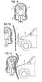
- Figure 1 shows three stages A, B and C depicting the child safety seat according to the invention per se in A, the child safety seat according to the invention prior to an impact in B, and the child safety seat according to the invention in the moment right after an impact in C.
- part A the child safety seat according to the invention is shown schematically having a shell 2, panels 3 attached to the shell 2 in which the side-impact-pusher-elements 1 are located.
- the child safety seat comprises a seat area 4 in which a passenger, presumably a child 6 is seated.
- part B the location of a door of a vehicle 7 is shown which is adjacent to the child safety seat.
- the vehicle 8 is about to have a side impact on the vehicle 7.
- FIG. 2 shows in more detail the transformation from stage A shown in the left hand side as standby stage and the activated stage shown on the right hand side indicated with B.
- the side-impact-pusher-element 1 is depicted in a cross sectional view showing a pusher area 11 and a energy absorbing area 10 as part of the side-impact-pusher-element 1 which is located between shell 2 and panel 3.
- the panel 3 will be pushed towards the shell 2 and by that the energy absorbi ng area 10 will absorb energy by either breaki ng off or bei ng deformed.
- the pusher area 11 will intrude into the sitting area (not shown) to push the passenger 6 (not shown) to reduce the distance of the child 6 to the side wings.
- Figure 3 gives a constructional view of the child safety seat in two stages A and B, whereas the top view A shows the standby stage with side-impact-pusher-elements 1 in the side wings 5 which is shown next to the seat area 4.
- the pusher elements 1 are activated and pushed inside towards to seat area 4.
Landscapes
- Engineering & Computer Science (AREA)
- Aviation & Aerospace Engineering (AREA)
- Transportation (AREA)
- Mechanical Engineering (AREA)
- Health & Medical Sciences (AREA)
- Child & Adolescent Psychology (AREA)
- General Health & Medical Sciences (AREA)
- Seats For Vehicles (AREA)
Abstract
Description
- The invention relates to a child safety seat for a vehicle which allows to improve the side-impact-protection of a passenger in a safety seat.
- In the art, numerous child safety seats are known which are firmly fixed to the vehicle, e.g. by means of ISOFIX. It is also known in the art that child safety seats comprise side wings which protect the child in the safety seat in case of a side impact since the side wings will absorb energy of an intruding door or vehicle before energy will reach the passenger.
- It has been a need to constantly improve the safety of a child sitting in a child safety seat in case of a side impact. Technical solutions to improve the safety include a plurality of technical devices such as airbags, foam bags or similar devices.
- Due to the dimensional restrictions, in particular to stay within certain width for ISOFIX chairs, however, limitations may apply with regard to the thickness of the side wings.
- An object of the invention is to improve significantly the safety of a child sitting in a safety seat in a vehicle in case of a side impact.
- This problem will be solved by a child safety seat for a vehicle according to the invention comprising an outer shell with a seating area for a child and side wings located on both sides of the seating area, characterized that at least one side wing comprises at least one side-impact-pusher-element.
- Advantageously, the child safety seat further comprises at least one side-impact-pusher-element with an energy absorbing area to be bent off, deformed from or separated from said side-impact-pusher-element or destroyed upon a side impact on the vehicle.
- Advantageously, said energy absorbing area of that side-impact-pusher-element is ring-shaped adjacent to a groove which separates said energy absorbing area from a pusher area, whereas said side-impact-pusher is made of substantially rigid synthetic material and the at least one side-impact-pusher-element is located in a cut-out of the at least one side wing.
- Advantageously, the cut-out has substantially the same shape as the pusher area of said side-impact-pusher-element and the cut-out is designed to let said pusher area of the side-impact-pusher-element pass through towards the seat area upon a side impact on the vehicle.
- In another preferred embodiment of the present invention the cut-out comprises means that are extending across the cut-out and are designed to break or deform when the pusher of the side-impact-pusher-element passes through towards the seat area upon a side impact on the vehicle.
- Advantageously, the means is made of a mesh which extends over the cut-out and the mesh will be disintegrated from the seat area upon a side impact on the vehicle.
- Advantageously, the child safety seat according to the invention may comprise several side-impact-pusher-elements whereas the location of the side-impact-pusher-elements is chosen so that the child may benefit from the side-impact-pusher-elements and is firmly held in the seat in case of a side impact on the vehicle. Preferably the side-impact-pusher-elements are located between a side panel and the shell of the safety seat.
- The inventive side-impact-pusher-elements meet the technical demands for holding a child in a child safety seat while at the same time the outer dimensions of the child safety seat will not be extending beyond the limits according to the legal requirements, e.g. ISOFIX limits.
- Another advantage of the side-impact-pusher-elements is that the side wings will function as the first contact of the child safety seat and an intruding door in case of a side impact. The impact will result in a compression of the side wings and the side panels. This energy will be utilized to push the side-impact-pusher-elements towards the child seating in the safety seat. The incoming force will compress the side panels of the safety seat which will absorb a first amount of energy. Upon a side impact, in conventional state of the art safety seats the person sitting in the seat will be subject to an acceleration which will rapidly be stopped when reaching the other end of the safety seat. The sudden acceleration and sudden deceleration with collision of structural elements of the child safety seat may cause damage.
- With the child safety seat according to the invention implementing the side-impact-pusher-elements the energy of the side impact will be used to transport the side-impact-pusher-elements from the outside area of the child safety seat into it seating area, preferably the side panels into the inner area of the child safety seats and by that reducing the possible area in which the child may be accelerated and decelerated.
- The achieved space reduction may be in the range of 5 to 50% preferably between 10 and 35%. According to the invention, the location of the side-impact-pusher-system as well as the number of implemented side-impact-pusher-elements in a child safety seat will be determined upon the size of the child safety seat, the age group to which the child safety seat designated and where the side-impact-pusher-elements will be located to achieve the described technical effect.
- In order to optimize the technical effect of the side-impact-pusher-system, the shape, size and location of the side-impact-pusher-element is of paramount importance. Since it is advantageous to reduce the space of the child safety seat occupied by the child at least one side-impact-pusher-element may be located in the side panels in the height of the pelvis and legs of the passenger. Another side-impact-pusher-element may be located on the height of the shoulder of the passenger.
- Another location may be the head area even if the head of the passenger is already protected by a partly surrounding headrest. The shape of the side-impact-pusher-element can vary and may comprise shapes of almost rectangular, oval, round, almost oval with round ages, kidney shaped or other shapes that prove to be advantageous to fulfill the object of the present invention.
- Besides the technical effect to reduce the seating space within the child safety seat, the movement of the side-impact-pusher-element activated on a side impact on the vehicle is also designed to absorb energy. Various possibilities are available to reduce and absorb energy when moving a side-impact-pusher-element according to the invention.
- In a preferred embodiment the pusher element comprises legs that will be bent, deformed, disintegrated or broken off in order to be first pushed from a cut-out in the shell of the child safety seat and also to be driven into the sitting area of the child safety seat.
- According to other embodiments of the inventions, energy absorption during the position change of the side-imact-pusher-element can be achieved through friction, elastic material that will be compressed such as springs or other suitable ways.
- The energy absorption will take place in the energy absorbing element and the rest of the energy will be directed along the occupant strong load paths, e.g. the pelvic and shoulder area to avoid injury to more fragile body areas such as chest and abdomen.
- The use of the child safety seat according to the invention will result in an inventive process for improving the safety of a passenger seated in a safety seat in a vehicle in case of a side impact of said vehicle, comprising the steps:
- fixing said safety seat in said vehicle;
- upon side impact:
- incoming door of said vehicle is making contact with outer surface of said side-impact-pusher;
- Energy absorbing area of said side-impact-pusher is absorbing energy while said side-impact-pusher is being pressed through a cut out of the side wing of said safety seat;
- said side-impact-pusher is making contact to said passenger to stop movement of said passenger;
- In the following, a preferred embodiment of the present invention will be explained in more detail by means of drawings:
-
Fig. 1 shows the invention concept of the side-impact-pusher system in three stages; -
Fig. 2 shows one embodiment of a side-impact pusher in a standby position and an activated position; -
Fig. 3 a schematic perspective view of a child safety seat in a standby position and an activated position -
Figure 1 shows three stages A, B and C depicting the child safety seat according to the invention per se in A, the child safety seat according to the invention prior to an impact in B, and the child safety seat according to the invention in the moment right after an impact in C. - In
Figure 1 , part A the child safety seat according to the invention is shown schematically having ashell 2,panels 3 attached to theshell 2 in which the side-impact-pusher-elements 1 are located. The child safety seat comprises aseat area 4 in which a passenger, presumably achild 6 is seated. - According to
Figure 1 , part B the location of a door of avehicle 7 is shown which is adjacent to the child safety seat. Thevehicle 8 is about to have a side impact on thevehicle 7. - In the event of a side impact by
vehicle 8 onvehicle 7, the door or door element is being deformed and making contact with the side-impact-pusher-elements 1 of the child safety seat. -
Figure 2 shows in more detail the transformation from stage A shown in the left hand side as standby stage and the activated stage shown on the right hand side indicated with B. - The side-impact-pusher-element 1 according to the preferred embodiment of the present invention is depicted in a cross sectional view showing a
pusher area 11 and aenergy absorbing area 10 as part of the side-impact-pusher-element 1 which is located betweenshell 2 andpanel 3. in the event of an impact shown by means of an arrow on the right hand side of part B ofFigure 2 , thepanel 3 will be pushed towards theshell 2 and by that the energy absorbi ngarea 10 will absorb energy by either breaki ng off or bei ng deformed. - The
pusher area 11 will intrude into the sitting area (not shown) to push the passenger 6 (not shown) to reduce the distance of thechild 6 to the side wings. -
Figure 3 gives a constructional view of the child safety seat in two stages A and B, whereas the top view A shows the standby stage with side-impact-pusher-elements 1 in theside wings 5 which is shown next to theseat area 4. In the below view B the pusher elements 1 are activated and pushed inside towards toseat area 4. -
- 1
- Side-impact-pusher element
- 2
- Shell
- 3
- Panel
- 4
- Seat area
- 5
- Side wing
- 6
- Child
- 7
- Vehicle
- 8
- Impacting vehicle
- 10
- Energy absorbing area
- 11
- Pusher area
- 12
- Cut-out
Claims (14)
- Child safety seat for a vehicle comprising an outer shell (2) with a seating area (4) for a child (6) and side wings (5) located on both sides of the seating area (4), characterized in that at least one side wing (5) comprises at least one side-impact-pusher element (1).
- Child safety seat according to claim 1, characterized in that the at least one side-impact-pusher element (1) is provided with an energy absorbing area (10) to be bent off, deformed from or separated from said side-impact-pusher element (1) or destroyed upon a side impact on the vehicle (7).
- Child safety seat according to claim 2, characterized in that said energy absorbing area (10) of said side-impact-pusher element (1) is ring-shaped adjacent to a groove which separates said energy absorbing area (10) from a pusher area (11).
- Child safety seat according to any of the previous claims, characterized in that said side-impact-pusher element (1) is made of substantially rigid synthetic material.
- Child safety seat according to any of the previous claims, characterized in that the at least one side-impact-pusher element (1) is located in a cut-out (12) of the at least one side wing (5).
- Child safety seat according to claim 5, characterized in that said cut-out (12) has substantially the same shape as the pusher area (11) of said side-impact-pusher element (1).
- Child safety seat according to claim 5, characterized in said cut-out (12) is designed to let said pusher area (11) of said side-impact-pusher element (1) pass through towards said seat area (4) upon a side impact on said vehicle (7).
- Child safety seat according to claim 7, characterized in that said cut-out comprises means that are extending across said cut-out and are designed to break off or deform when said pusher of said side-impact-pusher element passes through towards said seat area upon a side impact of said vehicle.
- Child safety seat according to claim 8, characterized in that said means is made of a mesh which extends over said cut-out.
- Child safety seat according to claim 9, characterized in that said mesh will be disintegrated from said seat area upon a side impact of said vehicle.
- Child safety seat according to any of the previous claims, characterized in that said side wings (5) comprise a plurality of side-impact-pusher elements (1).
- Child safety seat according to any of the previous claims, characterized in that said side-impact-pusher element (1) is located between a side panel (3) and said shell (2) of said safety seat.
- Child safety seat according to claim 12, characterized in that the side-impact-pusher element (1) is fixed in said cut-out (12).
- Process for improving the safety of a passenger seated in a safety seat in a vehicle in case of a side impact of said vehicle, comprising the steps:- fixing said safety seat in said vehicle;- upon side impact:- incoming door of said vehicle is making contact with outer surface of said side-impact-pusher;- Energy absorbing area of said side-impact-pusher is absorbing energy while said side-impact-pusher is being pressed through a cut out of the side wing of said safety seat;- said side-impact-pusher is making contact to said passenger to stop movement of said passenger;
Priority Applications (7)
| Application Number | Priority Date | Filing Date | Title |
|---|---|---|---|
| ES11007467.1T ES2538327T3 (en) | 2011-09-13 | 2011-09-13 | Child safety seat for vehicles |
| EP11007467.1A EP2570299B1 (en) | 2011-09-13 | 2011-09-13 | Child safety seat for vehicle |
| US13/607,172 US8684456B2 (en) | 2011-09-13 | 2012-09-07 | Child safety seat for vehicle |
| AU2012216718A AU2012216718B2 (en) | 2011-09-13 | 2012-09-07 | Child safety seat for vehicle |
| CA2789617A CA2789617C (en) | 2011-09-13 | 2012-09-12 | Child safety seat for vehicle |
| KR1020120101366A KR101466790B1 (en) | 2011-09-13 | 2012-09-13 | Child safety seat for vehicle |
| CN201210338389.1A CN103072497B (en) | 2011-09-13 | 2012-09-13 | Vehicle child safety seat and the method improving passenger safety |
Applications Claiming Priority (1)
| Application Number | Priority Date | Filing Date | Title |
|---|---|---|---|
| EP11007467.1A EP2570299B1 (en) | 2011-09-13 | 2011-09-13 | Child safety seat for vehicle |
Publications (2)
| Publication Number | Publication Date |
|---|---|
| EP2570299A1 true EP2570299A1 (en) | 2013-03-20 |
| EP2570299B1 EP2570299B1 (en) | 2015-03-04 |
Family
ID=45062757
Family Applications (1)
| Application Number | Title | Priority Date | Filing Date |
|---|---|---|---|
| EP11007467.1A Active EP2570299B1 (en) | 2011-09-13 | 2011-09-13 | Child safety seat for vehicle |
Country Status (7)
| Country | Link |
|---|---|
| US (1) | US8684456B2 (en) |
| EP (1) | EP2570299B1 (en) |
| KR (1) | KR101466790B1 (en) |
| CN (1) | CN103072497B (en) |
| AU (1) | AU2012216718B2 (en) |
| CA (1) | CA2789617C (en) |
| ES (1) | ES2538327T3 (en) |
Cited By (8)
| Publication number | Priority date | Publication date | Assignee | Title |
|---|---|---|---|---|
| EP2826662A1 (en) * | 2013-07-16 | 2015-01-21 | BRITAX RÖMER Kindersicherheit GmbH | Child safety seat |
| US9211820B2 (en) * | 2012-11-01 | 2015-12-15 | Graco Children's Products Inc. | Child safety seat with side impact energy redirection |
| EP2993078A1 (en) * | 2014-09-05 | 2016-03-09 | HTS Hans Torgersen & Sonn AS | Side impact protection for child safety seats |
| DE102015113836A1 (en) * | 2015-08-20 | 2017-02-23 | Recaro Child Safety Gmbh & Co. Kg | Child seat protector |
| RU2739509C2 (en) * | 2018-01-24 | 2020-12-25 | БРИТАКС РЁМЕР Киндерзигерайт ГмбХ | Retractable protective element for use in child safety seat |
| WO2021055337A1 (en) * | 2019-09-16 | 2021-03-25 | Monahan Products, LLC | Child carrier with side impact protection |
| US11511656B2 (en) | 2021-03-24 | 2022-11-29 | Monahan Products, LLC | Child restraint system with side impact bumper |
| IT202200013201A1 (en) * | 2022-06-22 | 2023-12-22 | Artsana Spa | Sensorized car seat |
Families Citing this family (21)
| Publication number | Priority date | Publication date | Assignee | Title |
|---|---|---|---|---|
| FR2986195A1 (en) * | 2012-01-31 | 2013-08-02 | Dorel France Sa | CHILD CAR SEAT, INTENDED TO BE SOLIDARIZED AT THE SEAT OF A MOTOR VEHICLE. |
| AU2013248252B2 (en) * | 2012-10-25 | 2017-09-21 | Britax Childcare Pty Ltd | Restraint cushioning improvements |
| US8911015B2 (en) | 2013-03-05 | 2014-12-16 | Yochanan Cohen | Car seat |
| US9487110B2 (en) | 2014-03-05 | 2016-11-08 | Pidyon Controls Inc. | Car seat |
| US10220734B2 (en) | 2013-03-05 | 2019-03-05 | Pidyon Controls Inc. | Car seat |
| US9616782B2 (en) | 2014-08-29 | 2017-04-11 | Pidyon Controls Inc. | Car seat vehicle connection system, apparatus, and method |
| MX2017013976A (en) | 2015-05-12 | 2018-03-14 | Pidyon Controls Inc | Car seat and connection system. |
| CA2930939C (en) * | 2015-05-27 | 2019-02-26 | Wonderland Nurserygoods Company Limited | Child safety seat and support base thereof |
| AU2017279736B2 (en) * | 2016-12-23 | 2023-12-14 | Britax Childcare Pty Ltd | Impact energy absorbing device |
| DE202017107887U1 (en) | 2017-12-22 | 2018-01-12 | Cybex Gmbh | Child seat for attachment to a motor vehicle seat |
| CN110001467A (en) * | 2018-01-05 | 2019-07-12 | 大一其株式会社 | The device for impact absorbing of children car seat |
| CN109278601B (en) * | 2018-08-29 | 2023-08-15 | 布童安全科技(宁波)有限公司 | A child safety seat headrest and its assembly process |
| CN109278602B (en) * | 2018-08-29 | 2024-05-24 | 布童安全科技(宁波)有限公司 | A head and neck side wing shock absorbing structure, a safety headrest and a child safety seat |
| CN109624801B (en) * | 2018-12-25 | 2024-04-09 | 清华大学苏州汽车研究院(相城) | Active side impact energy absorption mechanism and child safety seat |
| CN113386639A (en) * | 2020-03-13 | 2021-09-14 | 宝钜瑞士股份有限公司 | Child safety seat |
| CN113815502B (en) * | 2020-06-19 | 2024-07-26 | 宝钜瑞士股份有限公司 | Child safety seat and side-impact protection mechanism thereof |
| CN113859065B (en) | 2020-06-30 | 2024-07-09 | 宝钜瑞士股份有限公司 | Child safety seat and side impact protection mechanism |
| CN115158122B (en) * | 2022-07-13 | 2023-09-22 | 黄淮学院 | Intelligent networking automobile cabin and application method thereof |
| WO2025072394A1 (en) * | 2023-09-28 | 2025-04-03 | Wonderland Switzerland Ag | Side impact protection on car seat |
| CN117325726A (en) * | 2023-10-23 | 2024-01-02 | 广西双英集团股份有限公司 | Rotary blocking device for automobile seat cushion |
| US20250360849A1 (en) * | 2024-05-21 | 2025-11-27 | Dorel Juvenile Group, Inc. | Child restraint |
Citations (3)
| Publication number | Priority date | Publication date | Assignee | Title |
|---|---|---|---|---|
| US20010043001A1 (en) * | 1998-01-27 | 2001-11-22 | Aprica Kassai Kabushikikaisha | Child seat with movable side head guards |
| JP2004314800A (en) * | 2003-04-16 | 2004-11-11 | Takata Corp | Child seat |
| US20100026064A1 (en) * | 2008-07-30 | 2010-02-04 | Cosco Management, Inc. | Energy-dissipation system |
Family Cites Families (9)
| Publication number | Priority date | Publication date | Assignee | Title |
|---|---|---|---|---|
| JP2004314799A (en) | 2003-04-16 | 2004-11-11 | Takata Corp | Child seat |
| US7125073B2 (en) * | 2003-02-25 | 2006-10-24 | Takata Corporation | Child seat |
| US7232182B2 (en) * | 2003-02-25 | 2007-06-19 | Takata Corporation | Child seat |
| JP2004314798A (en) | 2003-04-16 | 2004-11-11 | Takata Corp | Child seat |
| JP2005001541A (en) * | 2003-06-12 | 2005-01-06 | Takata Corp | Child seat |
| US7748781B2 (en) * | 2008-01-14 | 2010-07-06 | Eric Bass | Head and body protection child safety seat |
| US7726734B2 (en) * | 2008-07-22 | 2010-06-01 | Britax Child Safety, Inc. | Juvenile seating with resilient side impact protection |
| EP2578444B2 (en) * | 2009-07-14 | 2020-10-28 | BRITAX RÖMER Kindersicherheit GmbH | Child seat with side impact protection |
| CN201685730U (en) * | 2009-10-30 | 2010-12-29 | 好孩子儿童用品有限公司 | child car seat |
-
2011
- 2011-09-13 EP EP11007467.1A patent/EP2570299B1/en active Active
- 2011-09-13 ES ES11007467.1T patent/ES2538327T3/en active Active
-
2012
- 2012-09-07 US US13/607,172 patent/US8684456B2/en active Active
- 2012-09-07 AU AU2012216718A patent/AU2012216718B2/en not_active Expired - Fee Related
- 2012-09-12 CA CA2789617A patent/CA2789617C/en active Active
- 2012-09-13 KR KR1020120101366A patent/KR101466790B1/en active Active
- 2012-09-13 CN CN201210338389.1A patent/CN103072497B/en active Active
Patent Citations (3)
| Publication number | Priority date | Publication date | Assignee | Title |
|---|---|---|---|---|
| US20010043001A1 (en) * | 1998-01-27 | 2001-11-22 | Aprica Kassai Kabushikikaisha | Child seat with movable side head guards |
| JP2004314800A (en) * | 2003-04-16 | 2004-11-11 | Takata Corp | Child seat |
| US20100026064A1 (en) * | 2008-07-30 | 2010-02-04 | Cosco Management, Inc. | Energy-dissipation system |
Cited By (25)
| Publication number | Priority date | Publication date | Assignee | Title |
|---|---|---|---|---|
| US9211820B2 (en) * | 2012-11-01 | 2015-12-15 | Graco Children's Products Inc. | Child safety seat with side impact energy redirection |
| EP2826662A1 (en) * | 2013-07-16 | 2015-01-21 | BRITAX RÖMER Kindersicherheit GmbH | Child safety seat |
| WO2015007372A1 (en) * | 2013-07-16 | 2015-01-22 | BRITAX RÖMER Kindersicherheit GmbH | Child safety seat |
| EP3858663A1 (en) * | 2013-07-16 | 2021-08-04 | BRITAX RÖMER Kindersicherheit GmbH | Child safety seat |
| AU2014292483C1 (en) * | 2013-07-16 | 2019-09-19 | Britax Romer Kindersicherheit Gmbh | Child safety seat |
| EP3437923A1 (en) * | 2013-07-16 | 2019-02-06 | BRITAX RÖMER Kindersicherheit GmbH | Child safety seat |
| EP3437920A1 (en) * | 2013-07-16 | 2019-02-06 | BRITAX RÖMER Kindersicherheit GmbH | Child safety seat |
| US9908444B2 (en) | 2013-07-16 | 2018-03-06 | BRITAX RÖMER Kindersicherheit GmbH | Child safety seat |
| EP3437922A1 (en) * | 2013-07-16 | 2019-02-06 | BRITAX RÖMER Kindersicherheit GmbH | Child safety seat |
| AU2014292483B2 (en) * | 2013-07-16 | 2018-04-19 | Britax Romer Kindersicherheit Gmbh | Child safety seat |
| RU2657660C2 (en) * | 2013-07-16 | 2018-06-14 | Бритакс Рёмер Киндерзихерхайт Гмбх | Child safety seat |
| EP2826662B1 (en) | 2013-07-16 | 2018-09-19 | BRITAX RÖMER Kindersicherheit GmbH | Child safety seat |
| EP3437921A1 (en) * | 2013-07-16 | 2019-02-06 | BRITAX RÖMER Kindersicherheit GmbH | Child safety seat |
| EP2993078B1 (en) | 2014-09-05 | 2017-03-22 | HTS Hans Torgersen & Sonn AS | Side impact protection for child safety seats |
| EP2993078A1 (en) * | 2014-09-05 | 2016-03-09 | HTS Hans Torgersen & Sonn AS | Side impact protection for child safety seats |
| CN107921892A (en) * | 2015-08-20 | 2018-04-17 | 瑞凯威儿童安全有限责任两合公司 | child seat protector |
| WO2017029272A1 (en) * | 2015-08-20 | 2017-02-23 | Recaro Child Safety Gmbh & Co. Kg | Child car seat protection device |
| DE102015113836A1 (en) * | 2015-08-20 | 2017-02-23 | Recaro Child Safety Gmbh & Co. Kg | Child seat protector |
| CN107921892B (en) * | 2015-08-20 | 2020-10-23 | 瑞凯威儿童安全有限责任两合公司 | Child seat protection device |
| DE102015113836B4 (en) * | 2015-08-20 | 2020-11-05 | Recaro Child Safety Gmbh & Co. Kg | Child seat protection device |
| RU2739509C2 (en) * | 2018-01-24 | 2020-12-25 | БРИТАКС РЁМЕР Киндерзигерайт ГмбХ | Retractable protective element for use in child safety seat |
| WO2021055337A1 (en) * | 2019-09-16 | 2021-03-25 | Monahan Products, LLC | Child carrier with side impact protection |
| US11318867B2 (en) | 2019-09-16 | 2022-05-03 | Monahan Products, LLC | Child carrier with side impact protection |
| US11511656B2 (en) | 2021-03-24 | 2022-11-29 | Monahan Products, LLC | Child restraint system with side impact bumper |
| IT202200013201A1 (en) * | 2022-06-22 | 2023-12-22 | Artsana Spa | Sensorized car seat |
Also Published As
| Publication number | Publication date |
|---|---|
| EP2570299B1 (en) | 2015-03-04 |
| KR20130029030A (en) | 2013-03-21 |
| US20130062917A1 (en) | 2013-03-14 |
| US8684456B2 (en) | 2014-04-01 |
| CN103072497B (en) | 2017-03-01 |
| AU2012216718B2 (en) | 2014-07-03 |
| AU2012216718A1 (en) | 2013-03-28 |
| KR101466790B1 (en) | 2014-11-28 |
| ES2538327T3 (en) | 2015-06-19 |
| CA2789617A1 (en) | 2013-03-13 |
| CA2789617C (en) | 2017-06-27 |
| CN103072497A (en) | 2013-05-01 |
Similar Documents
| Publication | Publication Date | Title |
|---|---|---|
| US8684456B2 (en) | Child safety seat for vehicle | |
| EP2222500B1 (en) | Child restraint apparatus for vehicle | |
| EP4035954B1 (en) | Airbag device and vehicle seat | |
| EP4043295B1 (en) | Airbag device and vehicle seat | |
| CN102271962A (en) | Method for securing and securing a vehicle occupant and securing and securing device for securing a vehicle occupant | |
| CN109263999A (en) | Security constraint protection towards the aircraft passenger that aircraft side is taken one's seat | |
| CN103332162A (en) | Car back row safety protection device | |
| EP3623209A1 (en) | Rear-facing occupant protection device | |
| EP3351433B1 (en) | Buckling inducing-type vehicle crash boxes and vehicle back beam having same | |
| CN112339697B (en) | Airbag device | |
| US10870375B2 (en) | Additive collapsible seat | |
| JP5963072B2 (en) | Railway vehicle. | |
| CN110789421B (en) | Armrest for vehicle, door interior trim panel assembly and vehicle | |
| WO2012066274A1 (en) | A seat for absorbing a force | |
| EP3326860B1 (en) | Energy absorbing assembly for a seat | |
| KR101327135B1 (en) | Device of air belt | |
| CN115447328B (en) | Seat and flying device | |
| JP5223074B2 (en) | Railway vehicle | |
| JPWO2006095803A1 (en) | Airbag device | |
| JP2021046179A (en) | Vehicle cabin structure | |
| JP2013244822A (en) | Shock absorbing structure of vehicular door | |
| JP2014162375A (en) | Vehicular seat |
Legal Events
| Date | Code | Title | Description |
|---|---|---|---|
| PUAI | Public reference made under article 153(3) epc to a published international application that has entered the european phase |
Free format text: ORIGINAL CODE: 0009012 |
|
| AK | Designated contracting states |
Kind code of ref document: A1 Designated state(s): AL AT BE BG CH CY CZ DE DK EE ES FI FR GB GR HR HU IE IS IT LI LT LU LV MC MK MT NL NO PL PT RO RS SE SI SK SM TR |
|
| AX | Request for extension of the european patent |
Extension state: BA ME |
|
| 17P | Request for examination filed |
Effective date: 20130920 |
|
| RBV | Designated contracting states (corrected) |
Designated state(s): AL AT BE BG CH CY CZ DE DK EE ES FI FR GB GR HR HU IE IS IT LI LT LU LV MC MK MT NL NO PL PT RO RS SE SI SK SM TR |
|
| 17Q | First examination report despatched |
Effective date: 20140305 |
|
| GRAP | Despatch of communication of intention to grant a patent |
Free format text: ORIGINAL CODE: EPIDOSNIGR1 |
|
| INTG | Intention to grant announced |
Effective date: 20140930 |
|
| GRAS | Grant fee paid |
Free format text: ORIGINAL CODE: EPIDOSNIGR3 |
|
| GRAA | (expected) grant |
Free format text: ORIGINAL CODE: 0009210 |
|
| AK | Designated contracting states |
Kind code of ref document: B1 Designated state(s): AL AT BE BG CH CY CZ DE DK EE ES FI FR GB GR HR HU IE IS IT LI LT LU LV MC MK MT NL NO PL PT RO RS SE SI SK SM TR |
|
| REG | Reference to a national code |
Ref country code: GB Ref legal event code: FG4D |
|
| REG | Reference to a national code |
Ref country code: CH Ref legal event code: EP |
|
| REG | Reference to a national code |
Ref country code: IE Ref legal event code: FG4D |
|
| REG | Reference to a national code |
Ref country code: AT Ref legal event code: REF Ref document number: 713545 Country of ref document: AT Kind code of ref document: T Effective date: 20150415 |
|
| REG | Reference to a national code |
Ref country code: DE Ref legal event code: R096 Ref document number: 602011014243 Country of ref document: DE Effective date: 20150416 |
|
| REG | Reference to a national code |
Ref country code: SE Ref legal event code: TRGR |
|
| REG | Reference to a national code |
Ref country code: ES Ref legal event code: FG2A Ref document number: 2538327 Country of ref document: ES Kind code of ref document: T3 Effective date: 20150619 |
|
| REG | Reference to a national code |
Ref country code: AT Ref legal event code: MK05 Ref document number: 713545 Country of ref document: AT Kind code of ref document: T Effective date: 20150304 Ref country code: NL Ref legal event code: VDEP Effective date: 20150304 |
|
| PG25 | Lapsed in a contracting state [announced via postgrant information from national office to epo] |
Ref country code: FI Free format text: LAPSE BECAUSE OF FAILURE TO SUBMIT A TRANSLATION OF THE DESCRIPTION OR TO PAY THE FEE WITHIN THE PRESCRIBED TIME-LIMIT Effective date: 20150304 Ref country code: HR Free format text: LAPSE BECAUSE OF FAILURE TO SUBMIT A TRANSLATION OF THE DESCRIPTION OR TO PAY THE FEE WITHIN THE PRESCRIBED TIME-LIMIT Effective date: 20150304 Ref country code: NO Free format text: LAPSE BECAUSE OF FAILURE TO SUBMIT A TRANSLATION OF THE DESCRIPTION OR TO PAY THE FEE WITHIN THE PRESCRIBED TIME-LIMIT Effective date: 20150604 Ref country code: LT Free format text: LAPSE BECAUSE OF FAILURE TO SUBMIT A TRANSLATION OF THE DESCRIPTION OR TO PAY THE FEE WITHIN THE PRESCRIBED TIME-LIMIT Effective date: 20150304 |
|
| REG | Reference to a national code |
Ref country code: LT Ref legal event code: MG4D |
|
| PG25 | Lapsed in a contracting state [announced via postgrant information from national office to epo] |
Ref country code: AT Free format text: LAPSE BECAUSE OF FAILURE TO SUBMIT A TRANSLATION OF THE DESCRIPTION OR TO PAY THE FEE WITHIN THE PRESCRIBED TIME-LIMIT Effective date: 20150304 Ref country code: RS Free format text: LAPSE BECAUSE OF FAILURE TO SUBMIT A TRANSLATION OF THE DESCRIPTION OR TO PAY THE FEE WITHIN THE PRESCRIBED TIME-LIMIT Effective date: 20150304 Ref country code: LV Free format text: LAPSE BECAUSE OF FAILURE TO SUBMIT A TRANSLATION OF THE DESCRIPTION OR TO PAY THE FEE WITHIN THE PRESCRIBED TIME-LIMIT Effective date: 20150304 Ref country code: GR Free format text: LAPSE BECAUSE OF FAILURE TO SUBMIT A TRANSLATION OF THE DESCRIPTION OR TO PAY THE FEE WITHIN THE PRESCRIBED TIME-LIMIT Effective date: 20150605 |
|
| PG25 | Lapsed in a contracting state [announced via postgrant information from national office to epo] |
Ref country code: NL Free format text: LAPSE BECAUSE OF FAILURE TO SUBMIT A TRANSLATION OF THE DESCRIPTION OR TO PAY THE FEE WITHIN THE PRESCRIBED TIME-LIMIT Effective date: 20150304 |
|
| PG25 | Lapsed in a contracting state [announced via postgrant information from national office to epo] |
Ref country code: RO Free format text: LAPSE BECAUSE OF FAILURE TO SUBMIT A TRANSLATION OF THE DESCRIPTION OR TO PAY THE FEE WITHIN THE PRESCRIBED TIME-LIMIT Effective date: 20150304 Ref country code: CZ Free format text: LAPSE BECAUSE OF FAILURE TO SUBMIT A TRANSLATION OF THE DESCRIPTION OR TO PAY THE FEE WITHIN THE PRESCRIBED TIME-LIMIT Effective date: 20150304 Ref country code: EE Free format text: LAPSE BECAUSE OF FAILURE TO SUBMIT A TRANSLATION OF THE DESCRIPTION OR TO PAY THE FEE WITHIN THE PRESCRIBED TIME-LIMIT Effective date: 20150304 Ref country code: SK Free format text: LAPSE BECAUSE OF FAILURE TO SUBMIT A TRANSLATION OF THE DESCRIPTION OR TO PAY THE FEE WITHIN THE PRESCRIBED TIME-LIMIT Effective date: 20150304 Ref country code: PT Free format text: LAPSE BECAUSE OF FAILURE TO SUBMIT A TRANSLATION OF THE DESCRIPTION OR TO PAY THE FEE WITHIN THE PRESCRIBED TIME-LIMIT Effective date: 20150706 |
|
| PG25 | Lapsed in a contracting state [announced via postgrant information from national office to epo] |
Ref country code: PL Free format text: LAPSE BECAUSE OF FAILURE TO SUBMIT A TRANSLATION OF THE DESCRIPTION OR TO PAY THE FEE WITHIN THE PRESCRIBED TIME-LIMIT Effective date: 20150304 Ref country code: IS Free format text: LAPSE BECAUSE OF FAILURE TO SUBMIT A TRANSLATION OF THE DESCRIPTION OR TO PAY THE FEE WITHIN THE PRESCRIBED TIME-LIMIT Effective date: 20150704 |
|
| REG | Reference to a national code |
Ref country code: DE Ref legal event code: R097 Ref document number: 602011014243 Country of ref document: DE |
|
| PG25 | Lapsed in a contracting state [announced via postgrant information from national office to epo] |
Ref country code: IT Free format text: LAPSE BECAUSE OF FAILURE TO SUBMIT A TRANSLATION OF THE DESCRIPTION OR TO PAY THE FEE WITHIN THE PRESCRIBED TIME-LIMIT Effective date: 20150304 |
|
| PLBE | No opposition filed within time limit |
Free format text: ORIGINAL CODE: 0009261 |
|
| STAA | Information on the status of an ep patent application or granted ep patent |
Free format text: STATUS: NO OPPOSITION FILED WITHIN TIME LIMIT |
|
| PG25 | Lapsed in a contracting state [announced via postgrant information from national office to epo] |
Ref country code: DK Free format text: LAPSE BECAUSE OF FAILURE TO SUBMIT A TRANSLATION OF THE DESCRIPTION OR TO PAY THE FEE WITHIN THE PRESCRIBED TIME-LIMIT Effective date: 20150304 |
|
| 26N | No opposition filed |
Effective date: 20151207 |
|
| PG25 | Lapsed in a contracting state [announced via postgrant information from national office to epo] |
Ref country code: SI Free format text: LAPSE BECAUSE OF FAILURE TO SUBMIT A TRANSLATION OF THE DESCRIPTION OR TO PAY THE FEE WITHIN THE PRESCRIBED TIME-LIMIT Effective date: 20150304 |
|
| PG25 | Lapsed in a contracting state [announced via postgrant information from national office to epo] |
Ref country code: LU Free format text: LAPSE BECAUSE OF FAILURE TO SUBMIT A TRANSLATION OF THE DESCRIPTION OR TO PAY THE FEE WITHIN THE PRESCRIBED TIME-LIMIT Effective date: 20150913 Ref country code: MC Free format text: LAPSE BECAUSE OF FAILURE TO SUBMIT A TRANSLATION OF THE DESCRIPTION OR TO PAY THE FEE WITHIN THE PRESCRIBED TIME-LIMIT Effective date: 20150304 |
|
| REG | Reference to a national code |
Ref country code: CH Ref legal event code: PL |
|
| REG | Reference to a national code |
Ref country code: IE Ref legal event code: MM4A |
|
| PG25 | Lapsed in a contracting state [announced via postgrant information from national office to epo] |
Ref country code: CH Free format text: LAPSE BECAUSE OF NON-PAYMENT OF DUE FEES Effective date: 20150930 Ref country code: IE Free format text: LAPSE BECAUSE OF NON-PAYMENT OF DUE FEES Effective date: 20150913 Ref country code: LI Free format text: LAPSE BECAUSE OF NON-PAYMENT OF DUE FEES Effective date: 20150930 |
|
| PG25 | Lapsed in a contracting state [announced via postgrant information from national office to epo] |
Ref country code: BE Free format text: LAPSE BECAUSE OF FAILURE TO SUBMIT A TRANSLATION OF THE DESCRIPTION OR TO PAY THE FEE WITHIN THE PRESCRIBED TIME-LIMIT Effective date: 20150304 |
|
| REG | Reference to a national code |
Ref country code: FR Ref legal event code: PLFP Year of fee payment: 6 |
|
| PG25 | Lapsed in a contracting state [announced via postgrant information from national office to epo] |
Ref country code: MT Free format text: LAPSE BECAUSE OF FAILURE TO SUBMIT A TRANSLATION OF THE DESCRIPTION OR TO PAY THE FEE WITHIN THE PRESCRIBED TIME-LIMIT Effective date: 20150304 |
|
| PG25 | Lapsed in a contracting state [announced via postgrant information from national office to epo] |
Ref country code: HU Free format text: LAPSE BECAUSE OF FAILURE TO SUBMIT A TRANSLATION OF THE DESCRIPTION OR TO PAY THE FEE WITHIN THE PRESCRIBED TIME-LIMIT; INVALID AB INITIO Effective date: 20110913 Ref country code: SM Free format text: LAPSE BECAUSE OF FAILURE TO SUBMIT A TRANSLATION OF THE DESCRIPTION OR TO PAY THE FEE WITHIN THE PRESCRIBED TIME-LIMIT Effective date: 20150304 Ref country code: BG Free format text: LAPSE BECAUSE OF FAILURE TO SUBMIT A TRANSLATION OF THE DESCRIPTION OR TO PAY THE FEE WITHIN THE PRESCRIBED TIME-LIMIT Effective date: 20150304 |
|
| PG25 | Lapsed in a contracting state [announced via postgrant information from national office to epo] |
Ref country code: CY Free format text: LAPSE BECAUSE OF FAILURE TO SUBMIT A TRANSLATION OF THE DESCRIPTION OR TO PAY THE FEE WITHIN THE PRESCRIBED TIME-LIMIT Effective date: 20150304 |
|
| REG | Reference to a national code |
Ref country code: FR Ref legal event code: PLFP Year of fee payment: 7 |
|
| PG25 | Lapsed in a contracting state [announced via postgrant information from national office to epo] |
Ref country code: MK Free format text: LAPSE BECAUSE OF FAILURE TO SUBMIT A TRANSLATION OF THE DESCRIPTION OR TO PAY THE FEE WITHIN THE PRESCRIBED TIME-LIMIT Effective date: 20150304 |
|
| REG | Reference to a national code |
Ref country code: FR Ref legal event code: PLFP Year of fee payment: 8 |
|
| PG25 | Lapsed in a contracting state [announced via postgrant information from national office to epo] |
Ref country code: AL Free format text: LAPSE BECAUSE OF FAILURE TO SUBMIT A TRANSLATION OF THE DESCRIPTION OR TO PAY THE FEE WITHIN THE PRESCRIBED TIME-LIMIT Effective date: 20150304 |
|
| PGFP | Annual fee paid to national office [announced via postgrant information from national office to epo] |
Ref country code: TR Payment date: 20240904 Year of fee payment: 14 |
|
| PGFP | Annual fee paid to national office [announced via postgrant information from national office to epo] |
Ref country code: DE Payment date: 20250919 Year of fee payment: 15 |
|
| PGFP | Annual fee paid to national office [announced via postgrant information from national office to epo] |
Ref country code: GB Payment date: 20250923 Year of fee payment: 15 |
|
| PGFP | Annual fee paid to national office [announced via postgrant information from national office to epo] |
Ref country code: FR Payment date: 20250922 Year of fee payment: 15 |
|
| PGFP | Annual fee paid to national office [announced via postgrant information from national office to epo] |
Ref country code: SE Payment date: 20250922 Year of fee payment: 15 |
|
| PGFP | Annual fee paid to national office [announced via postgrant information from national office to epo] |
Ref country code: ES Payment date: 20251020 Year of fee payment: 15 |