EP2570081A1 - Method and apparatus for processing image, ultrasound diagnosis apparatus, and medical imaging system - Google Patents
Method and apparatus for processing image, ultrasound diagnosis apparatus, and medical imaging system Download PDFInfo
- Publication number
- EP2570081A1 EP2570081A1 EP20120161828 EP12161828A EP2570081A1 EP 2570081 A1 EP2570081 A1 EP 2570081A1 EP 20120161828 EP20120161828 EP 20120161828 EP 12161828 A EP12161828 A EP 12161828A EP 2570081 A1 EP2570081 A1 EP 2570081A1
- Authority
- EP
- European Patent Office
- Prior art keywords
- image
- ultrasound
- standard
- diagnosis
- plane
- Prior art date
- Legal status (The legal status is an assumption and is not a legal conclusion. Google has not performed a legal analysis and makes no representation as to the accuracy of the status listed.)
- Granted
Links
Images




Classifications
-
- A—HUMAN NECESSITIES
- A61—MEDICAL OR VETERINARY SCIENCE; HYGIENE
- A61B—DIAGNOSIS; SURGERY; IDENTIFICATION
- A61B8/00—Diagnosis using ultrasonic, sonic or infrasonic waves
- A61B8/46—Ultrasonic, sonic or infrasonic diagnostic devices with special arrangements for interfacing with the operator or the patient
- A61B8/461—Displaying means of special interest
- A61B8/466—Displaying means of special interest adapted to display 3D data
-
- A—HUMAN NECESSITIES
- A61—MEDICAL OR VETERINARY SCIENCE; HYGIENE
- A61B—DIAGNOSIS; SURGERY; IDENTIFICATION
- A61B8/00—Diagnosis using ultrasonic, sonic or infrasonic waves
-
- A—HUMAN NECESSITIES
- A61—MEDICAL OR VETERINARY SCIENCE; HYGIENE
- A61B—DIAGNOSIS; SURGERY; IDENTIFICATION
- A61B6/00—Apparatus or devices for radiation diagnosis; Apparatus or devices for radiation diagnosis combined with radiation therapy equipment
- A61B6/02—Arrangements for diagnosis sequentially in different planes; Stereoscopic radiation diagnosis
- A61B6/03—Computed tomography [CT]
-
- A—HUMAN NECESSITIES
- A61—MEDICAL OR VETERINARY SCIENCE; HYGIENE
- A61B—DIAGNOSIS; SURGERY; IDENTIFICATION
- A61B8/00—Diagnosis using ultrasonic, sonic or infrasonic waves
- A61B8/46—Ultrasonic, sonic or infrasonic diagnostic devices with special arrangements for interfacing with the operator or the patient
- A61B8/461—Displaying means of special interest
-
- A—HUMAN NECESSITIES
- A61—MEDICAL OR VETERINARY SCIENCE; HYGIENE
- A61B—DIAGNOSIS; SURGERY; IDENTIFICATION
- A61B8/00—Diagnosis using ultrasonic, sonic or infrasonic waves
- A61B8/46—Ultrasonic, sonic or infrasonic diagnostic devices with special arrangements for interfacing with the operator or the patient
- A61B8/461—Displaying means of special interest
- A61B8/463—Displaying means of special interest characterised by displaying multiple images or images and diagnostic data on one display
-
- A—HUMAN NECESSITIES
- A61—MEDICAL OR VETERINARY SCIENCE; HYGIENE
- A61B—DIAGNOSIS; SURGERY; IDENTIFICATION
- A61B8/00—Diagnosis using ultrasonic, sonic or infrasonic waves
- A61B8/48—Diagnostic techniques
- A61B8/483—Diagnostic techniques involving the acquisition of a 3D volume of data
-
- A—HUMAN NECESSITIES
- A61—MEDICAL OR VETERINARY SCIENCE; HYGIENE
- A61B—DIAGNOSIS; SURGERY; IDENTIFICATION
- A61B8/00—Diagnosis using ultrasonic, sonic or infrasonic waves
- A61B8/52—Devices using data or image processing specially adapted for diagnosis using ultrasonic, sonic or infrasonic waves
- A61B8/5215—Devices using data or image processing specially adapted for diagnosis using ultrasonic, sonic or infrasonic waves involving processing of medical diagnostic data
- A61B8/523—Devices using data or image processing specially adapted for diagnosis using ultrasonic, sonic or infrasonic waves involving processing of medical diagnostic data for generating planar views from image data in a user selectable plane not corresponding to the acquisition plane
-
- A—HUMAN NECESSITIES
- A61—MEDICAL OR VETERINARY SCIENCE; HYGIENE
- A61B—DIAGNOSIS; SURGERY; IDENTIFICATION
- A61B8/00—Diagnosis using ultrasonic, sonic or infrasonic waves
- A61B8/52—Devices using data or image processing specially adapted for diagnosis using ultrasonic, sonic or infrasonic waves
- A61B8/5215—Devices using data or image processing specially adapted for diagnosis using ultrasonic, sonic or infrasonic waves involving processing of medical diagnostic data
- A61B8/5238—Devices using data or image processing specially adapted for diagnosis using ultrasonic, sonic or infrasonic waves involving processing of medical diagnostic data for combining image data of patient, e.g. merging several images from different acquisition modes into one image
- A61B8/5261—Devices using data or image processing specially adapted for diagnosis using ultrasonic, sonic or infrasonic waves involving processing of medical diagnostic data for combining image data of patient, e.g. merging several images from different acquisition modes into one image combining images from different diagnostic modalities, e.g. ultrasound and X-ray
-
- G—PHYSICS
- G16—INFORMATION AND COMMUNICATION TECHNOLOGY [ICT] SPECIALLY ADAPTED FOR SPECIFIC APPLICATION FIELDS
- G16H—HEALTHCARE INFORMATICS, i.e. INFORMATION AND COMMUNICATION TECHNOLOGY [ICT] SPECIALLY ADAPTED FOR THE HANDLING OR PROCESSING OF MEDICAL OR HEALTHCARE DATA
- G16H30/00—ICT specially adapted for the handling or processing of medical images
- G16H30/20—ICT specially adapted for the handling or processing of medical images for handling medical images, e.g. DICOM, HL7 or PACS
-
- G—PHYSICS
- G16—INFORMATION AND COMMUNICATION TECHNOLOGY [ICT] SPECIALLY ADAPTED FOR SPECIFIC APPLICATION FIELDS
- G16H—HEALTHCARE INFORMATICS, i.e. INFORMATION AND COMMUNICATION TECHNOLOGY [ICT] SPECIALLY ADAPTED FOR THE HANDLING OR PROCESSING OF MEDICAL OR HEALTHCARE DATA
- G16H30/00—ICT specially adapted for the handling or processing of medical images
- G16H30/40—ICT specially adapted for the handling or processing of medical images for processing medical images, e.g. editing
-
- A—HUMAN NECESSITIES
- A61—MEDICAL OR VETERINARY SCIENCE; HYGIENE
- A61B—DIAGNOSIS; SURGERY; IDENTIFICATION
- A61B5/00—Measuring for diagnostic purposes; Identification of persons
- A61B5/74—Details of notification to user or communication with user or patient; User input means
- A61B5/742—Details of notification to user or communication with user or patient; User input means using visual displays
- A61B5/7425—Displaying combinations of multiple images regardless of image source, e.g. displaying a reference anatomical image with a live image
-
- A—HUMAN NECESSITIES
- A61—MEDICAL OR VETERINARY SCIENCE; HYGIENE
- A61B—DIAGNOSIS; SURGERY; IDENTIFICATION
- A61B8/00—Diagnosis using ultrasonic, sonic or infrasonic waves
- A61B8/44—Constructional features of the ultrasonic, sonic or infrasonic diagnostic device
- A61B8/4405—Device being mounted on a trolley
-
- A—HUMAN NECESSITIES
- A61—MEDICAL OR VETERINARY SCIENCE; HYGIENE
- A61B—DIAGNOSIS; SURGERY; IDENTIFICATION
- A61B8/00—Diagnosis using ultrasonic, sonic or infrasonic waves
- A61B8/46—Ultrasonic, sonic or infrasonic diagnostic devices with special arrangements for interfacing with the operator or the patient
- A61B8/467—Ultrasonic, sonic or infrasonic diagnostic devices with special arrangements for interfacing with the operator or the patient characterised by special input means
Definitions
- the present invention relates to a method and apparatus for processing an image, an ultrasound diagnosis apparatus, and a medical image system.
- a diagnosis image of an object is obtained by an ultrasound diagnosis apparatus, a computed tomography (CT) system, a magnetic resonance imaging (MRI) system, or the like.
- CT computed tomography
- MRI magnetic resonance imaging
- a user needs to scan a region of interest of an object by using a probe installed in the ultrasound diagnosis apparatus.
- the present invention provides a method and apparatus for processing an image, an ultrasound diagnosis apparatus, and a medical image system which improve the accuracy of reading an ultrasound image.
- the present invention also provides a non-transitory computer readable recording medium having recorded thereon a program for executing the method in a computer.
- the technical objects of the present invention are not limited thereto and include other objects.
- an image processing apparatus including an image data acquiring unit for acquiring ultrasound image data indicating information about an object; a standard image generating unit for generating an ultrasound standard image from the ultrasound image data based on a reference image with respect to at least one standard plane; and a display unit for displaying the ultrasound standard image.
- a method of processing an image including acquiring ultrasound image data indicating information about an object; generating an ultrasound standard image from the generated ultrasound image data, based on a reference image with respect to at least one standard plane; and displaying the generated ultrasound standard image.
- a non-transitory computer readable recording medium having recorded thereon a program for executing the method of processing an image and the method of displaying a diagnosis image.
- FIG. 1 is a block diagram of an image processing apparatus 100 according to an embodiment of the present invention.
- the image processing apparatus 100 includes an image data acquiring unit 110, a standard image generating unit 120, and a display unit 130.
- FIG. 1 Elements reflated to the present embodiment are illustrated in FIG. 1 . However, it will be understood by those of ordinary skill in the art that besides the elements illustrated in FIG. 1 other general elements may be further included.
- the standard image generating unit 120 of FIG. 1 may correspond to a single processor or a plurality of processors.
- the processor may be embodied with an array of a plurality of logic gates, or may be embodied with a combination of a general microprocessor and a memory where a program to be run in the microprocessor is stored. It will be also understood by those of ordinary skill in the art that it may be embodied with another form of hardware.
- the image processing apparatus 100 processes an image of an object and provides the image to a user.
- the user is generally a medical expert such as a doctor, a nurse, or a medical image expert, but is not limited thereto.
- the object may be a human body, liver, heart, brain, abdomen, breasts, or the like, but is not limited thereto.
- the image processing apparatus 100 may be installed in an ultrasound diagnosis apparatus (not shown), but is not limited thereto. That is, the image processing apparatus 100 may be installed in a general computer system, a laptop, a personal digital assistant (PDA), or the like.
- an ultrasound diagnosis apparatus not shown
- PDA personal digital assistant
- the image data acquiring unit 110 acquires ultrasound image data indicating information regarding the object.
- the image data acquiring unit 110 may acquire the ultrasound image data from an echo signal that is formed by reflecting an ultrasound signal transmitted to the object.
- the image data acquiring unit 110 may be, but is not limited to, a probe that acquires the echo signal that is reflected off the object and may acquire image data that is previously stored.
- the standard image generating unit 120 generates an ultrasound standard image from the ultrasound image data that is acquired by the image data acquiring unit 110, based on a reference image with respect to at least one standard plane.
- the standard image generating unit 120 may include a digital signal processor (DSP) (not shown) and a digital scan converter (DSC) (not shown).
- DSP digital signal processor
- DSC digital scan converter
- the DSP forms image data indicating a b-mode (brightness mode), c-mode (color mode), or d-mode (Doppler mode) by using the ultrasound image data acquired by the image data acquiring unit 110.
- the DSC according to the present embodiment generates an image that is scan-converted in order to display the image data that is formed by the DSP.
- the at least one standard plane corresponds to a standard plane that is used to diagnose the human body.
- the at least one standard plane may include at least one of a sagittal plane, a coronal plane, and an axial plane, but is not limited thereto.
- the standard plane will be described below in detail with reference to FIG. 2 .
- a reference image according to the present embodiment may include at least one of a sagittal ultrasound image with respect to a sagittal plane, a coronal ultrasound image with respect to a coronal plane, and an axial ultrasound image with respect to an axial plane.
- the sagittal ultrasound image, the coronal ultrasound image, and the axial ultrasound image may be previously stored in a database (not shown), but are not limited thereto. That is, the sagittal ultrasound image, the coronal ultrasound image, and the axial ultrasound image may be acquired from an external source outside the image processing apparatus 100.
- the standard image generating unit 120 may generate an ultrasound standard image with respect to at least one of the sagittal plane, the coronal plane, and the axial plane of the object, based on at least one of the sagittal ultrasound image, the coronal ultrasound image, and the axial ultrasound image.
- the standard image generating unit 120 may perform an image registration process on the ultrasound image data based on a reference image to generate an ultrasound standard image.
- the image registration process may be performed using an image registration algorithm.
- the image registration algorithm may include a mean squares metric technique, a normalized correlation metric technique, a mean reciprocal square difference technique, a mutual information metric technique, or the like.
- the image registration algorithm may include an image-based registration algorithm, a sensor-based global positing system (GPS) algorithm, or the like.
- the image-based registration algorithm may include a method of comparing intensities of images or comparing characteristics such as edges of images.
- a method of generating a standard image by performing the image registration process on the ultrasound image data in the standard image generation unit 120 will be described below in detail with reference to FIGS. 3 and 4 .
- the standard image generating unit 120 may perform the image registration process based on the sagittal ultrasound image to generate an ultrasound standard image with respect to the sagittal plane of the object, may perform the image registration process based on the coronal ultrasound image to generate an ultrasound standard image with respect to the coronal plane of the object, or may perform the image registration process based on the axial ultrasound image to generate an ultrasound standard image with respect to the axial plane of the object.
- the standard image generating unit 120 since the standard image generating unit 120 generates an ultrasound standard image, a standardized diagnosis image is used, thereby improving the accuracy of diagnosis of the object.
- An ultrasound signal may be transmitted to the object and an ultrasound image may be obtained from an echo signal that is obtained by reflecting the transmitted ultrasound signal.
- an apparatus for example, a probe
- an ultrasound image of the object may be an ultrasound image of a region that is determined by a user's manipulation of the probe.
- the standard image generating unit 120 since the standard image generating unit 120 generates the ultrasound standard image, different ultrasound images may not be obtained with respect to the same region of interest according to the user's manipulation of the probe, thereby improving the accuracy of diagnosis.
- the standard image generating unit 120 may generate the ultrasound standard image according to whether the ultrasound image data contains a region that is likely to have a disease.
- the region that is likely to have a disease may include a lesion, a mass, a tumor, and the like.
- the standard image generating unit 120 may analyze the ultrasound image data, may determine whether the ultrasound image data contains a region that is likely to have a disease, and may generate the ultrasound standard image only when the ultrasound image data contains the region that is likely to have a disease according to the determination result.
- the standard image generating unit 120 may determine whether the ultrasound image data contains the region that is likely to have a disease by generating an ultrasound image or may determine whether image data on which beamforming is performed contains the region that is likely to have a disease.
- the ultrasound standard image may be prevented from being generated unnecessarily.
- the standard image generating unit 120 is not particularly limited. When a user wants screening using a standard plane, the standard image generating unit 120 may generate a standard image prior to diagnosing the user. That is, the standard image generating unit 120 may generate the ultrasound standard image regardless of whether there is a region that is likely to have a disease in the object and may diagnose the object by using the generated ultrasound standard image.
- the diagnosis apparatuses other than the ultrasound diagnosis apparatus may include a magnetic resonance imaging (MRI) system, a computed tomography (CT) system, a positron emission tomography (PET) system, or the like, but are not limited thereto.
- MRI magnetic resonance imaging
- CT computed tomography
- PET positron emission tomography
- the standard image generating unit 120 may automatically perform the above-described functions. That is, when the image data acquiring unit 110 acquires image data of the object, the standard image generating unit 120 may automatically generate the ultrasound standard image or may automatically determine whether there is a region that is likely to have a disease and may generate the ultrasound standard image.
- the display unit 130 may display the ultrasound standard image generated by the standard image generating unit 120.
- the display unit 130 may be an output device installed in the image processing apparatus 100, such as a monitor, a touch panel, a liquid crystal display (LCD), or the like, and a software module for driving the output device.
- the user may view the ultrasound standard image of the object through the display unit 130.
- the image processing apparatus 100 Since the image processing apparatus 100 generates the ultrasound standard image about the ultrasound image that may vary according to the user's manipulation of the probe, the user may easily and rapidly diagnose the object.
- FIG. 2 shows an example of a standard plane, according to an embodiment of the present invention.
- a case where an object is a human body is shown, for convenience of description.
- FIG. 2 shows a drawing 21 indicating an object including a sagittal plane 211, a coronal plane 212, and an axial plane 213.
- the axial plane 213 may be a transverse plane.
- the sagittal plane 211 indicates a side of the object.
- the sagittal plane 211 may include a sagittal cross sectional plane.
- the sagittal plane 211 indicates a plane that divides the object between left region and right region.
- the coronal plane 212 indicates the front of the object.
- the coronal plane 212 indicates a plane that vertically divides the brain with reference to the front of the object.
- the front of the object may mean a face.
- the axial plane 213 indicates a cross section of the object.
- the axial plane 213 is a plane that horizontally divides the object.
- the axial plane 213 indicates a plane that divides the object between upper region and lower region.
- the standard plane may further include other planes in addition to the sagittal plane 211, the coronal plane 212, and the axial plane 213.
- FIG. 2 shows a single sagittal plane 211, a single coronal plane 212, and a single axial plane 213 only, but the present invention is not limited thereto. Planes that are in parallel to the sagittal plane 211, the coronal plane 212, and the axial plane 213 may be included in the sagittal plane 211, the coronal plane 212, and the axial plane 213 respectively.
- FIG. 3 is a diagram for describing a method of generating a standard image in the standard image generating unit 120 of FIG. 1 , according to an embodiment of the present invention.
- the method will be described with reference to FIGS. 1 and 3 .
- FIG. 3 shows a case where the image data acquiring unit 110 acquires three-dimensional (3D) image data by using a two-dimensional (2D) array probe, but the present invention is not limited thereto.
- Ultrasound image data 31 may be acquired from an echo signal that is reflected from an object.
- the ultrasound image data 31 may be formed by performing receive beamforming on the echo signal that is reflected from the object.
- the ultrasound image data 31 is formed with respect to an axial direction indicating a propagation direction of an ultrasound signal, a lateral direction indicating a moving direction of a scan line, and an elevation direction indicating a depth direction of an ultrasound image.
- the standard image generating unit 120 performs an image registration process on the ultrasound image data 31 based on a reference image to generate a standard image. That is, the standard image generating unit 120 generates the standard image from the ultrasound image data 31 based on the reference image by using an image registration algorithm.
- the standard image generating unit 120 may compare the intensity of the reference image with the intensity of the ultrasound image data 31 and may generate the standard image having the most similar intensity to the reference image from the ultrasound image data 31.
- the standard image generating unit 120 may compare characteristics such as an edge or the like of the reference image with the characteristics of the ultrasound image data 31 and may generate the standard image having the most similar characteristics to the reference image from the ultrasound image data 31.
- the standard image generating unit 120 may perform a modification process such as a synthesis process, an interpolation process, a translation process, a rotation process, a scaling process, or the like on the ultrasound image data 31 to generate the standard image.
- a modification process such as a synthesis process, an interpolation process, a translation process, a rotation process, a scaling process, or the like
- the standard image generating unit 120 may generate the standard image of the object from the ultrasound image data 31 on which beamforming is performed. In this case, the standard image generating unit 120 may generate the standard image of the object without a loss in data.
- the standard image generating unit 120 is not limited thereto and may generate the standard image of the object from a plurality of images that are scan-converted. That is, the standard image generating unit 120 may perform a modification process such as a synthesis process, an interpolation process, a translation process, a rotation process, a scaling process, or the like on the scan-converted plurality of images to generate a single standard image. In this case, the standard image generating unit 120 may generate the standard image at a higher speed than the case where the ultrasound image data 31 on which beamforming is performed is used.
- the standard image generating unit 120 may generate the standard image by using the ultrasound image data 31 on which beamforming is performed or at least one of a plurality of images that are scan-converted.
- a user may select the ultrasound image data 31 on which beamforming is performed or at least one of a plurality of images that are scan-converted to generate the standard image.
- FIG. 4 is a diagram for describing a method of generating a standard image in the standard image generating unit 120 of FIG. 1 , according to another embodiment of the present invention. Hereinafter, the method will be described with reference to FIGS. 1 and 4 .
- FIG. 4 shows a standard plane 42 of an object 41.
- the standard image generating unit 120 may generate an ultrasound standard image with respect to the standard plane 42 by using the ultrasound image data with respect to the first plane 431, the second plane 432, and the third plane 433.
- FIG. 4 shows a case of a single standard plane 42, but the present invention is not limited thereto.
- the standard image generating unit 120 may generate standard images with respect to a plurality of standard planes, respectively.
- a standard image with respect to a standard plane may be acquired regardless of a user's manipulation of a probe, thereby improving the accuracy of reading an ultrasound image of the user.
- FIG. 5 is a block diagram of an image processing apparatus 100 according to another embodiment of the present invention.
- the image processing apparatus 100 includes an image data acquiring unit 110, a database 112, a search unit 114, a standard image generating unit 120, a comparison image acquiring unit 125, and a display unit 130.
- FIG. 5 Elements related to the present embodiment are illustrated in FIG. 5 . However, it will be understood by those of ordinary skill in the art that besides the elements illustrated in FIG. 5 other general elements may be further included.
- the image processing apparatus 100 of FIG. 5 is an example of the image processing apparatus 100 of FIG. 1 .
- the image processing apparatus 100 according to the present embodiment is not limited to including units of FIG. 5 . Accordingly, although omitted, details described with reference to the image processing apparatus 100 of FIG. 1 are applied to the image processing apparatus 100 of FIG. 5 .
- the image processing apparatus 100 processes an image of an object and provides the processed image to a user.
- the image data acquiring unit 110 acquires ultrasound image data indicating information about the object.
- the database 112 stores a reference image with respect to at least one standard plane, for each respective information about a human body and information about a region of the human body.
- the reference information stored in the database 112 may be a general image of an object without disease.
- the information about the human body may contain, but is not limited to, sex, height, age, or the like and the information about the human body region may contain, but is not limited to, a liver, breast, abdomen, brain, or the like. That is, the database 112 may store the reference image with respect to at least one standard plane for each of various information about the human bodies and various information about the human body regions.
- the search unit 114 searches for a reference image corresponding to information about the human body and information about the human body region of the object.
- the search unit 114 searches for a reference image of the heart of the thirty year-old woman in the database 112.
- the search unit 114 searches for the reference image in consideration of the information about the height, weight, and the like of the object.
- information about the human body and information about the human body region of the object may be input by a user through a user interface unit (not shown), but the present invention is not limited thereto. That is, the information about the human body region may be recognized from image data acquired by the image data acquiring unit 110.
- the standard image generating unit 120 generates an ultrasound standard image from the ultrasound image data, based on a reference image with respect to at least one standard image. For example, the standard image generating unit 120 generates the ultrasound standard image, based on the reference image that is found by the search unit 114.
- the standard image generating unit 120 may generate a standard image in consideration of the human body information of the object, thereby further improving the accuracy of image registration.
- the comparison image acquiring unit 125 acquires at least one comparison image indicating information about the object by using a diagnosis technique different from a diagnosis technique of acquiring the ultrasound image data.
- Examples of the diagnosis technique different from a diagnosis technique of acquiring ultrasound image data may include a diagnosis technique using a magnetic resonance imaging (MRI) system, a diagnosis technique using a computed tomography (CT) system, and a diagnosis technique using a positron emission tomography (PET) system.
- MRI magnetic resonance imaging
- CT computed tomography
- PET positron emission tomography
- comparison image may includes, but is not limited to, at least one of a MRI image, a CT image, and a PET image of the object.
- the comparison image acquiring unit 125 may acquire the comparison image through a communication interface unit (not shown) from outside the image processing apparatus 100, but the present invention is not limited thereto. That is, the comparison image acquiring unit 125 may acquire the comparison image that is previously measured and is stored in the database 112.
- the display unit 130 displays an ultrasound standard image.
- the display unit 130 displays the ultrasound standard image together with at least one comparison image acquired by the compare image acquiring unit 125.
- each of the at least one comparison image and the ultrasound standard image, which are displayed by the display unit 130 may be images with respect to the same standard plane.
- the display unit 130 displays a sagittal ultrasound standard image with respect to a sagittal plane of the object
- at least one of a sagittal CT image, a sagittal MRI image, and a sagittal PET image with respect to the sagittal plane of the same object may be displayed together with a sagittal ultrasound standard image.
- the display unit 130 displays the ultrasound standard image together with at least one comparison image acquired by the comparison image acquiring unit 125.
- the display unit 130 may sequentially display the at least one comparison image and the ultrasound standard image on a single screen, or may display the at least one comparison image and the ultrasound standard image by converting one another in consideration of information input by a user.
- the display unit 130 may sequential display ultrasound standard images of the same object with a time interval. Thus, a change in the size of a tumor or the like may be easily traced.
- the image processing apparatus 100 is used, thereby improving the accuracy of reading an ultrasound image by radiation oncologists, image medical scientists, or the like who are accustomed to a standard plane such as a sagittal plane, a coronal plane, an axial plane, or the like.
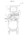
- FIG. 6 is a diagram of an ultrasound diagnosis apparatus 600 including an image processing apparatus 100, according to an embodiment of the present invention.
- the ultrasound diagnosis apparatus 600 includes a probe 610, a user interface unit 620, and a main system 630.
- the user interface unit 620 includes an input unit 622 and a display unit 624.
- the ultrasound diagnosis apparatus 600 may be, but is not limited to, an apparatus that transmits an ultrasound signal to an object and generates an ultrasound image by using an echo signal that is reflected from the object.
- the ultrasound diagnosis apparatus 600 may include the image processing apparatus 100 shown in FIGS 1 and 5 . Accordingly, although omitted, details described with reference to the image processing apparatus 100 of FIGS. 1 and 5 are applied to the ultrasound diagnosis apparatus 600 of FIG. 6 .
- the probe 610 transmits the ultrasound signal to the object and receives the echo signal reflected from the object.
- the probe 610 shown in FIG. 6 may be, but is not limited to, an example of the image data acquiring unit 110 of the image processing apparatus 100 of FIGS. 1 and 5 .
- the user interface unit 620 acquires input information from a user and displays output information to the user.
- the user interface unit 620 may include, but is not limited to, the input unit 622 and the display unit 624. That is, the user interface unit 620 may be embodied as a single unit having both input and output functions.
- the display unit 624 of FIG. 6 may be, but is not limited to, an example of the display unit 130 of the image processing apparatus 100 of FIGS. 1 and 5 .
- the user interface unit 620 may include, but is not limited to, any input/output device included in the ultrasound diagnosis apparatus 600, such as a keyboard, a mouse, a touch panel, a speaker, or the like, and any software for driving the input/output device.
- any input/output device included in the ultrasound diagnosis apparatus 600 such as a keyboard, a mouse, a touch panel, a speaker, or the like, and any software for driving the input/output device.
- the main system 630 controls an overall function of the ultrasound diagnosis apparatus 600. That is, the main system 630 controls the probe 610 and the user interface unit 620. According to the present embodiment, the main system 630 may include the database 112, the search unit 114, the standard image generating unit 120, and the comparison image acquiring unit 125 of the image processing apparatus 100 of FIGS. 1 and 5 .
- the ultrasound diagnosis apparatus 600 may generate an ultrasound diagnosis image or an ultrasound standard image of the object.
- the ultrasound diagnosis apparatus 600 may display the ultrasound standard image together with at least one comparison image that is acquired by using a diagnosis technique different from a diagnosis technique of acquiring the ultrasound image data, thereby improving the accuracy of reading an image by the user.
- FIG. 7 is a block diagram of a medical image system 700 induing an image processing apparatus 100, according to an embodiment of the present invention.
- the medical image system 700 includes the image processing apparatus 100, a diagnosis unit 710, a storage unit 720, and an output unit 730.
- the image processing apparatus 100 of FIG. 7 corresponds to an example of the image processing apparatus 100 of FIGS. 1 and 5 . Accordingly, although omitted here, details described with reference to the image processing apparatus 100 of FIGS. 1 and 5 are applied to the image processing apparatus 100 of FIG. 7 .
- the image processing apparatus 100 acquires ultrasound image data indicating information about an object and generates an ultrasound standard image of the ultrasound image data based on a reference image with respect to at least one standard plane. In addition, the image processing apparatus 100 acquires at least one comparison image indicating information about the object by using a diagnosis technique different from a diagnosis technique of acquiring the ultrasound image data. Thus, the image processing apparatus 100 may display the ultrasound standard image of the object together with the comparison image.
- the diagnosis unit 710 performs a diagnosis technique different from a diagnosis technique of acquiring the ultrasound image data. According to the result of the diagnosis technique different from a diagnosis technique of acquiring ultrasound image data, the image processing apparatus 100 may acquire at least one comparison image indicating the information about the object.
- the diagnosis unit 710 may perform a diagnosis technique using a MRI system for acquiring a MRI image, a diagnosis technique using a CT system, a diagnosis technique using a PET system, and the like.
- the image processing apparatus 100 may acquire at least one of a MRI image, a CT image, and a PET image of the object as the comparison image, through the diagnosis unit 710.
- the diagnosis unit 710 may perform diagnosis for acquiring the comparison image with respect to the same standard plane as that of the ultrasound standard image.
- the medical image system 700 may acquire at least one of a MRI image, a CT image, and a PET image of the object, which are previously measured in an external device and stored.
- the external device may be a MRI system, a CT system, a PET system, or the like.
- the storage unit 720 stores data that is generated during an operation of the medical image system 700.
- the storage unit 720 may store data output from the image processing apparatus 100, a diagnosis image generated by the image processing apparatus 100, and the like.
- the storage unit 720 may be any storage device such as a hard disk drive (HDD), a read only memory (ROM), a random access memory (RAM), a flash memory, and a memory card.
- the output unit 730 may transmit and receive data to and from an external device through a wired/wireless network or wired serial communication.
- the network may include the Internet, a local area network (LAN), a wireless local area network (WLAN), a wide area network (WAN), a personal area network (PAN), or the like, but are not limited thereto.
- the network may be any type network that transmits and receives information.
- the medical image system 700 may output the ultrasound standard image generated by the image processing apparatus 100 to an external device.
- the external device may include, but is not limited to, another medical image system which may be located at remote place, a fax machine, a general computer system, a PDA, or the like.
- the storage unit 720 and the output unit 730 further include an image reading function and a searching function so as to be integrated in the form of a picture archiving communication system (PACS).
- PACS picture archiving communication system
- FIG. 8 is a flowchart of a method of processing an image, according to an embodiment of the present invention.
- the method of processing the image includes time-series operations performed by the image processing apparatus 100, the ultrasound diagnosis apparatus 600, and the medical image system 700 shown in FIGS. 1 , and 5 through 7 . Accordingly, details described with reference to the image processing apparatus 100, the ultrasound diagnosis apparatus 600, and the medical image system 700 shown in FIGS. 1 , and 5 through 7 are also applicable to the method of processing the image of FIG. 8 .
- the image data acquiring unit 110 acquires ultrasound image data indicating information about an object.
- the image data acquiring unit 110 may acquire image data by using a probe.
- the standard image generating unit 120 generates an ultrasound standard image from the ultrasound image data acquired in operation 801, based on a reference image with respect to at least one standard plane.
- the reference image may include at least one of a sagittal ultrasound image with respect to a sagittal plane, a coronal ultrasound image with respect to a coronal plane, and an axial ultrasound image with respect to an axial plane.
- the display unit 130 displays the ultrasound standard image generated in operation 802.
- the display unit 130 may display the ultrasound standard image generated in operation 802 together with at least one comparison image acquired by using a diagnosis technique different from a diagnosis technique of acquiring the ultrasound image data.
- an ultrasound standard image with respect to a standard plane may be displayed, thereby improving the accuracy of reading an ultrasound image.
- an ultrasound diagnosis image and at least one comparison image that is acquired by using a diagnosis technique different from a diagnosis technique of acquiring the ultrasound image data may be viewed together, thereby improving the accuracy of diagnosis.
- FIG. 9 is a flowchart of displaying an image, according to an embodiment of the present invention.
- the method of displaying the image may include time-series operations performed by the image processing apparatus 100, the ultrasound diagnosis apparatus 600, and the medical image system 700 shown in FIGS. 1 , and 5 through 7 . Accordingly, although omitted, details described with reference to the image processing apparatus 100, the ultrasound diagnosis apparatus 600, and the medical image system 700 shown in FIGS. 1 , and 5 through 7 are also applicable to the method of displaying the image of FIG. 9 .
- the image data acquiring unit 110 acquires ultrasound image data indicating information about an object.
- the standard image generating unit 120 determines whether the ultrasound image data acquired in operation 901 contains a region that is likely to have a disease. According to the determination result, when the ultrasound image data does not contain the region that is likely to have a disease, the method proceeds to operation 903. When the ultrasound image data contains the region that is likely to have a disease, the method proceeds to operation 904.
- the display unit 130 displays an ultrasound image.
- the ultrasound image may be generated from the ultrasound image data.
- the ultrasound image data acquired in operation 901 does not contain the region that is likely to have a disease
- the ultrasound image may not be displayed and the procedure may be finished. In this case, operation 903 may not be performed.
- the search unit 114 searches the database 112 for a reference image corresponding to information about a human body and information about a region of the human body of the object.
- the database 112 stores a reference image with respect to at least one standard plane, for each respective information about the human body and information about the human body region.
- the standard image generating unit 120 In operation 905, the standard image generating unit 120 generates an ultrasound standard image from the ultrasound image data acquired in operation 901, based on the reference image that is searched for in operation 904.
- the comparison image acquiring unit 125 acquires at least one comparison image indicating information about the object by using a diagnosis technique different from a diagnosis technique of acquiring the ultrasound image data in operation 901.
- the display unit 130 displays the at least one comparison image acquired in operation 906 together with the ultrasound standard image generated in operation 905.
- an ultrasound image of an object and at least one comparison image may be viewed simultaneously on a single screen, thereby improving the accuracy of reading an image and improving the correctness and accuracy of diagnosis.
- the procedure shown in FIGS. 8 and 9 may be embodied in the forms of application program. Accordingly, the application may be executed in the form of a viewer in a general computer system, a PDA, a laptop computer, an ultrasound diagnosis apparatus, a medical image system, or the like. Thus, the user may conveniently use functions according to embodiments of the present invention.
- the image processing apparatus 100, the ultrasound diagnosis apparatus 600, and the medical image system 700 display the ultrasound standard image and the comparison image, but the present invention is not limited thereto. That is, the ultrasound standard image may be uploaded to another diagnosis apparatus (e.g., a MRI system, a CT system, or a PET system).
- another diagnosis apparatus e.g., a MRI system, a CT system, or a PET system.
- the accuracy of diagnosis of soft tissues that are barely viewable from a CT image may be improved. That is, the CT system displays the ultrasound standard image and a user reads the ultrasound standard image, thereby improving the accuracy of diagnosis.
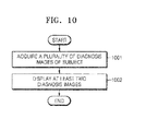
- FIG. 10 is a flowchart of displaying a diagnosis image, according to an embodiment of the present invention.
- the method of displaying the diagnosis image includes time-series operations performed by the image processing apparatus 100, the ultrasound diagnosis apparatus 600, and the medical image system 700 shown in FIGS. 1 , and 5 through 7 . Accordingly, details described with reference to the image processing apparatus 100, the ultrasound diagnosis apparatus 600, and the medical image system 700 shown in FIGS. 1 , and 5 through 7 are also applicable to the method of displaying the diagnosis image of FIG. 10 .
- a diagnosis image viewer that is executed by a processor obtains a plurality of diagnosis images of an object, which are generated by at least two diagnosis apparatuses using different diagnosis techniques.
- the diagnosis image viewer may receive a plurality of diagnosis images from at least two diagnosis apparatuses.
- examples of the diagnosis apparatus may include an ultrasound system, a MRI system, a CT system, and a PET system.
- Examples of the diagnosis image may include an ultrasound image, an ultrasound standard image according to an embodiment of the present invention, a MRI image, a CT image, and a PET image.
- the diagnosis image viewer executed by the processor displays at least two diagnosis images together from among the plurality of diagnosis images obtained in operation 1001.
- the at least two diagnosis images may be selected by a user.
- the at least two diagnosis images may be obtained by using different diagnosis techniques, but are not limited thereto. That is, the at least two diagnosis images may be obtained by using the same diagnosis technique.
- diagnosis images obtained by using the same diagnosis technique are displayed together on a single screen
- the diagnosis images obtained by using the same diagnosis technique may be obtained with respect to the same region of an object with a time interval, or may be obtained with respect to different regions of the object.
- the diagnosis image viewer may be embodied in the form of application program by executing a processor included in a general computer system, a PDA, a laptop computer, a medical image system, or the like.
- a user may conveniently diagnose the object by using the diagnosis image viewer.
- an ultrasound standard image may be generated and displayed, different ultrasound images may not be obtained with respect to the same region of interest according to the user's manipulation of a probe, thereby improving the accuracy of diagnosis and the accuracy of reading an image of a user who views the ultrasound image.
- the embodiments of the present invention may be written as computer programs and can be implemented in general-use digital computers that execute the programs using a computer readable recording medium.
- a structure of data used in the above-described method may be recorded in a computer readable recording medium through various methods.
- the computer readable recording medium include magnetic storage media (e.g., ROMs, RAMs, universal serial buses (USBs), floppy disks, hard disks, etc.), optical recording media (e.g., CD-ROMs, or DVDs), and storage media such as PC interfaces (e.g., PCI, PCl-express, Wifi, etc.).
- an ultrasound standard image may be generated and displayed, different ultrasound images may not be obtained with respect to the same region of interest according to the user's manipulation of a probe, thereby improving the accuracy of diagnosis and the accuracy of reading an image of a user who searches for the ultrasound image.
Landscapes
- Health & Medical Sciences (AREA)
- Life Sciences & Earth Sciences (AREA)
- Engineering & Computer Science (AREA)
- Medical Informatics (AREA)
- General Health & Medical Sciences (AREA)
- Public Health (AREA)
- Nuclear Medicine, Radiotherapy & Molecular Imaging (AREA)
- Radiology & Medical Imaging (AREA)
- Surgery (AREA)
- Heart & Thoracic Surgery (AREA)
- Biomedical Technology (AREA)
- Molecular Biology (AREA)
- Physics & Mathematics (AREA)
- Animal Behavior & Ethology (AREA)
- Pathology (AREA)
- Biophysics (AREA)
- Veterinary Medicine (AREA)
- Computer Vision & Pattern Recognition (AREA)
- Epidemiology (AREA)
- Primary Health Care (AREA)
- Computer Graphics (AREA)
- General Engineering & Computer Science (AREA)
- High Energy & Nuclear Physics (AREA)
- Optics & Photonics (AREA)
- Ultra Sonic Daignosis Equipment (AREA)
- Measuring And Recording Apparatus For Diagnosis (AREA)
Abstract
Description
- This application claims the benefit of Korean Patent Application No.
10-2011-0094280, filed on September 19, 2011 - The present invention relates to a method and apparatus for processing an image, an ultrasound diagnosis apparatus, and a medical image system.
- A diagnosis image of an object is obtained by an ultrasound diagnosis apparatus, a computed tomography (CT) system, a magnetic resonance imaging (MRI) system, or the like. In this case, in order to obtain a diagnosis image by using an ultrasound diagnosis apparatus, a user needs to scan a region of interest of an object by using a probe installed in the ultrasound diagnosis apparatus.
- The present invention provides a method and apparatus for processing an image, an ultrasound diagnosis apparatus, and a medical image system which improve the accuracy of reading an ultrasound image. In addition, the present invention also provides a non-transitory computer readable recording medium having recorded thereon a program for executing the method in a computer. The technical objects of the present invention are not limited thereto and include other objects.
- According to an aspect of the present invention, there is provided an image processing apparatus including an image data acquiring unit for acquiring ultrasound image data indicating information about an object; a standard image generating unit for generating an ultrasound standard image from the ultrasound image data based on a reference image with respect to at least one standard plane; and a display unit for displaying the ultrasound standard image.
- According to another aspect of the present invention, there is provided a method of processing an image, the method including acquiring ultrasound image data indicating information about an object; generating an ultrasound standard image from the generated ultrasound image data, based on a reference image with respect to at least one standard plane; and displaying the generated ultrasound standard image.
- According to another aspect of the present invention, there is provided a non-transitory computer readable recording medium having recorded thereon a program for executing the method of processing an image and the method of displaying a diagnosis image.
- The above and other features and advantages of the present invention will become more apparent by describing in detail exemplary embodiments thereof with reference to the attached drawings in which:
-
FIG. 1 is a block diagram of an image processing apparatus according to an embodiment of the present invention; -
FIG. 2 shows an example of a standard plane, according to an embodiment of the present invention; -
FIG. 3 is a diagram for describing a method of generating a standard image in the a standard image generating unit ofFIG. 1 , according to an embodiment of the present invention; -
FIG. 4 is a diagram for describing a method of generating a standard image in the standard image generating unit ofFIG. 1 according to another embodiment of the present invention; -
FIG. 5 is a block diagram of an image processing apparatus according to another embodiment of the present invention; -
FIG. 6 is a diagram of an ultrasound diagnosis apparatus including an image processing apparatus, according to an embodiment of the present invention; -
FIG. 7 is a block diagram of a medical image system including an image processing apparatus, according to an embodiment of the present invention; -
FIG. 8 is a flowchart of a method of processing an image, according to an embodiment of the present invention; -
FIG. 9 is a flowchart of displaying an image, according to an embodiment of the present invention; and -
FIG. 10 is a flowchart of displaying a diagnosis image, according to an embodiment of the present invention. - Reference will now be made in detail to embodiments, examples of which are illustrated in the accompanying drawings, wherein like reference numerals refer to like elements throughout. In this regard, the present embodiments may have different forms and should not be construed as being limited to the descriptions set forth herein. Accordingly, the embodiments are merely described below, by referring to the figures, to explain aspects of the present description. Expressions such as "at least one of," when preceding a list of elements, modify the entire list of elements and do not modify the individual elements of the list.
-
FIG. 1 is a block diagram of animage processing apparatus 100 according to an embodiment of the present invention. Referring toFIG. 1 , theimage processing apparatus 100 includes an imagedata acquiring unit 110, a standardimage generating unit 120, and adisplay unit 130. - Elements reflated to the present embodiment are illustrated in
FIG. 1 . However, it will be understood by those of ordinary skill in the art that besides the elements illustrated inFIG. 1 other general elements may be further included. - The standard
image generating unit 120 ofFIG. 1 may correspond to a single processor or a plurality of processors. The processor may be embodied with an array of a plurality of logic gates, or may be embodied with a combination of a general microprocessor and a memory where a program to be run in the microprocessor is stored. It will be also understood by those of ordinary skill in the art that it may be embodied with another form of hardware. - The
image processing apparatus 100 processes an image of an object and provides the image to a user. In this case, the user is generally a medical expert such as a doctor, a nurse, or a medical image expert, but is not limited thereto. In addition, the object may be a human body, liver, heart, brain, abdomen, breasts, or the like, but is not limited thereto. - The
image processing apparatus 100 may be installed in an ultrasound diagnosis apparatus (not shown), but is not limited thereto. That is, theimage processing apparatus 100 may be installed in a general computer system, a laptop, a personal digital assistant (PDA), or the like. - The image
data acquiring unit 110 acquires ultrasound image data indicating information regarding the object. For example, the imagedata acquiring unit 110 may acquire the ultrasound image data from an echo signal that is formed by reflecting an ultrasound signal transmitted to the object. Thus, the imagedata acquiring unit 110 may be, but is not limited to, a probe that acquires the echo signal that is reflected off the object and may acquire image data that is previously stored. - The standard
image generating unit 120 generates an ultrasound standard image from the ultrasound image data that is acquired by the imagedata acquiring unit 110, based on a reference image with respect to at least one standard plane. For example, the standardimage generating unit 120 may include a digital signal processor (DSP) (not shown) and a digital scan converter (DSC) (not shown). The DSP according to the present embodiment forms image data indicating a b-mode (brightness mode), c-mode (color mode), or d-mode (Doppler mode) by using the ultrasound image data acquired by the imagedata acquiring unit 110. The DSC according to the present embodiment generates an image that is scan-converted in order to display the image data that is formed by the DSP. - According to the present embodiment, the at least one standard plane corresponds to a standard plane that is used to diagnose the human body. For example, the at least one standard plane may include at least one of a sagittal plane, a coronal plane, and an axial plane, but is not limited thereto. The standard plane will be described below in detail with reference to
FIG. 2 . - A reference image according to the present embodiment may include at least one of a sagittal ultrasound image with respect to a sagittal plane, a coronal ultrasound image with respect to a coronal plane, and an axial ultrasound image with respect to an axial plane. The sagittal ultrasound image, the coronal ultrasound image, and the axial ultrasound image may be previously stored in a database (not shown), but are not limited thereto. That is, the sagittal ultrasound image, the coronal ultrasound image, and the axial ultrasound image may be acquired from an external source outside the
image processing apparatus 100. - The standard
image generating unit 120 may generate an ultrasound standard image with respect to at least one of the sagittal plane, the coronal plane, and the axial plane of the object, based on at least one of the sagittal ultrasound image, the coronal ultrasound image, and the axial ultrasound image. - For example, the standard
image generating unit 120 may perform an image registration process on the ultrasound image data based on a reference image to generate an ultrasound standard image. In this case, the image registration process may be performed using an image registration algorithm. The image registration algorithm may include a mean squares metric technique, a normalized correlation metric technique, a mean reciprocal square difference technique, a mutual information metric technique, or the like. - In more detail, the image registration algorithm may include an image-based registration algorithm, a sensor-based global positing system (GPS) algorithm, or the like. The image-based registration algorithm may include a method of comparing intensities of images or comparing characteristics such as edges of images.
- A method of generating a standard image by performing the image registration process on the ultrasound image data in the standard
image generation unit 120 will be described below in detail with reference toFIGS. 3 and 4 . - The standard
image generating unit 120 may perform the image registration process based on the sagittal ultrasound image to generate an ultrasound standard image with respect to the sagittal plane of the object, may perform the image registration process based on the coronal ultrasound image to generate an ultrasound standard image with respect to the coronal plane of the object, or may perform the image registration process based on the axial ultrasound image to generate an ultrasound standard image with respect to the axial plane of the object. - According to the present embodiment, since the standard
image generating unit 120 generates an ultrasound standard image, a standardized diagnosis image is used, thereby improving the accuracy of diagnosis of the object. - An ultrasound signal may be transmitted to the object and an ultrasound image may be obtained from an echo signal that is obtained by reflecting the transmitted ultrasound signal. In this case, an apparatus (for example, a probe) for transmitting the ultrasound signal to the object may be manipulated by a user. Thus, an ultrasound image of the object may be an ultrasound image of a region that is determined by a user's manipulation of the probe.
- Thus, since the standard
image generating unit 120 generates the ultrasound standard image, different ultrasound images may not be obtained with respect to the same region of interest according to the user's manipulation of the probe, thereby improving the accuracy of diagnosis. - The standard
image generating unit 120 may generate the ultrasound standard image according to whether the ultrasound image data contains a region that is likely to have a disease. In this case, the region that is likely to have a disease may include a lesion, a mass, a tumor, and the like. - For example, the standard
image generating unit 120 may analyze the ultrasound image data, may determine whether the ultrasound image data contains a region that is likely to have a disease, and may generate the ultrasound standard image only when the ultrasound image data contains the region that is likely to have a disease according to the determination result. - In this case, the standard
image generating unit 120 may determine whether the ultrasound image data contains the region that is likely to have a disease by generating an ultrasound image or may determine whether image data on which beamforming is performed contains the region that is likely to have a disease. - Thus, when there is no region that is likely to have a disease in the object, the ultrasound standard image may be prevented from being generated unnecessarily.
- However, the standard
image generating unit 120 is not particularly limited. When a user wants screening using a standard plane, the standardimage generating unit 120 may generate a standard image prior to diagnosing the user. That is, the standardimage generating unit 120 may generate the ultrasound standard image regardless of whether there is a region that is likely to have a disease in the object and may diagnose the object by using the generated ultrasound standard image. - Thus, convenience for a user that is accustomed to diagnosis through diagnoisis image of diagnosis apparatuses other than the ultrasound diagnosis apparatus may be improved. In this case, the diagnosis apparatuses other than the ultrasound diagnosis apparatus may include a magnetic resonance imaging (MRI) system, a computed tomography (CT) system, a positron emission tomography (PET) system, or the like, but are not limited thereto.
- In addition, the standard
image generating unit 120 may automatically perform the above-described functions. That is, when the imagedata acquiring unit 110 acquires image data of the object, the standardimage generating unit 120 may automatically generate the ultrasound standard image or may automatically determine whether there is a region that is likely to have a disease and may generate the ultrasound standard image. - The
display unit 130 may display the ultrasound standard image generated by the standardimage generating unit 120. For example, thedisplay unit 130 may be an output device installed in theimage processing apparatus 100, such as a monitor, a touch panel, a liquid crystal display (LCD), or the like, and a software module for driving the output device. Thus, the user may view the ultrasound standard image of the object through thedisplay unit 130. - Since the
image processing apparatus 100 generates the ultrasound standard image about the ultrasound image that may vary according to the user's manipulation of the probe, the user may easily and rapidly diagnose the object. -
FIG. 2 shows an example of a standard plane, according to an embodiment of the present invention. InFIG. 2 , a case where an object is a human body is shown, for convenience of description.FIG. 2 shows a drawing 21 indicating an object including asagittal plane 211, acoronal plane 212, and anaxial plane 213. In this case, theaxial plane 213 may be a transverse plane. - For example, the
sagittal plane 211 indicates a side of the object. Thesagittal plane 211 may include a sagittal cross sectional plane. In more detail, thesagittal plane 211 indicates a plane that divides the object between left region and right region. - For example, the
coronal plane 212 indicates the front of the object. In more detail, thecoronal plane 212 indicates a plane that vertically divides the brain with reference to the front of the object. In this case, the front of the object may mean a face. - For example, the
axial plane 213 indicates a cross section of the object. In more detail, theaxial plane 213 is a plane that horizontally divides the object. In detail, theaxial plane 213 indicates a plane that divides the object between upper region and lower region. - According to the present embodiment, the standard plane may further include other planes in addition to the
sagittal plane 211, thecoronal plane 212, and theaxial plane 213. - In addition,
FIG. 2 shows a singlesagittal plane 211, a singlecoronal plane 212, and a singleaxial plane 213 only, but the present invention is not limited thereto. Planes that are in parallel to thesagittal plane 211, thecoronal plane 212, and theaxial plane 213 may be included in thesagittal plane 211, thecoronal plane 212, and theaxial plane 213 respectively. -
FIG. 3 is a diagram for describing a method of generating a standard image in the standardimage generating unit 120 ofFIG. 1 , according to an embodiment of the present invention. Hereinafter, the method will be described with reference toFIGS. 1 and3 . For convenience of description,FIG. 3 shows a case where the imagedata acquiring unit 110 acquires three-dimensional (3D) image data by using a two-dimensional (2D) array probe, but the present invention is not limited thereto. -
Ultrasound image data 31 may be acquired from an echo signal that is reflected from an object. In more detail, theultrasound image data 31 may be formed by performing receive beamforming on the echo signal that is reflected from the object. - Thus, the
ultrasound image data 31 is formed with respect to an axial direction indicating a propagation direction of an ultrasound signal, a lateral direction indicating a moving direction of a scan line, and an elevation direction indicating a depth direction of an ultrasound image. - Thus, the standard
image generating unit 120 performs an image registration process on theultrasound image data 31 based on a reference image to generate a standard image. That is, the standardimage generating unit 120 generates the standard image from theultrasound image data 31 based on the reference image by using an image registration algorithm. - For example, when an image registration algorithm for comparing the intensity of an image is used, the standard
image generating unit 120 may compare the intensity of the reference image with the intensity of theultrasound image data 31 and may generate the standard image having the most similar intensity to the reference image from theultrasound image data 31. - For example, when an image registration algorithm for comparing the characteristics of an image is used, the standard
image generating unit 120 may compare characteristics such as an edge or the like of the reference image with the characteristics of theultrasound image data 31 and may generate the standard image having the most similar characteristics to the reference image from theultrasound image data 31. - In this case, the standard
image generating unit 120 may perform a modification process such as a synthesis process, an interpolation process, a translation process, a rotation process, a scaling process, or the like on theultrasound image data 31 to generate the standard image. - Thus, the standard
image generating unit 120 may generate the standard image of the object from theultrasound image data 31 on which beamforming is performed. In this case, the standardimage generating unit 120 may generate the standard image of the object without a loss in data. - The standard
image generating unit 120 is not limited thereto and may generate the standard image of the object from a plurality of images that are scan-converted. That is, the standardimage generating unit 120 may perform a modification process such as a synthesis process, an interpolation process, a translation process, a rotation process, a scaling process, or the like on the scan-converted plurality of images to generate a single standard image. In this case, the standardimage generating unit 120 may generate the standard image at a higher speed than the case where theultrasound image data 31 on which beamforming is performed is used. - Thus, the standard
image generating unit 120 may generate the standard image by using theultrasound image data 31 on which beamforming is performed or at least one of a plurality of images that are scan-converted. In this case, a user may select theultrasound image data 31 on which beamforming is performed or at least one of a plurality of images that are scan-converted to generate the standard image. -
FIG. 4 is a diagram for describing a method of generating a standard image in the standardimage generating unit 120 ofFIG. 1 , according to another embodiment of the present invention. Hereinafter, the method will be described with reference toFIGS. 1 and4 . -
FIG. 4 shows astandard plane 42 of anobject 41. In this case, when the imagedata acquiring unit 110 acquires ultrasound image data with respect to afirst plane 431, asecond plane 432, and athird plane 433, the standardimage generating unit 120 may generate an ultrasound standard image with respect to thestandard plane 42 by using the ultrasound image data with respect to thefirst plane 431, thesecond plane 432, and thethird plane 433. -
FIG. 4 shows a case of a singlestandard plane 42, but the present invention is not limited thereto. The standardimage generating unit 120 may generate standard images with respect to a plurality of standard planes, respectively. - Thus, when the
image processing apparatus 100 is used, a standard image with respect to a standard plane may be acquired regardless of a user's manipulation of a probe, thereby improving the accuracy of reading an ultrasound image of the user. -
FIG. 5 is a block diagram of animage processing apparatus 100 according to another embodiment of the present invention. Referring toFIG. 5 , theimage processing apparatus 100 includes an imagedata acquiring unit 110, adatabase 112, asearch unit 114, a standardimage generating unit 120, a comparisonimage acquiring unit 125, and adisplay unit 130. - Elements related to the present embodiment are illustrated in
FIG. 5 . However, it will be understood by those of ordinary skill in the art that besides the elements illustrated inFIG. 5 other general elements may be further included. - The
image processing apparatus 100 ofFIG. 5 is an example of theimage processing apparatus 100 ofFIG. 1 . Thus, theimage processing apparatus 100 according to the present embodiment is not limited to including units ofFIG. 5 . Accordingly, although omitted, details described with reference to theimage processing apparatus 100 ofFIG. 1 are applied to theimage processing apparatus 100 ofFIG. 5 . - According to the present embodiment, the
image processing apparatus 100 processes an image of an object and provides the processed image to a user. - The image
data acquiring unit 110 acquires ultrasound image data indicating information about the object. - The
database 112 stores a reference image with respect to at least one standard plane, for each respective information about a human body and information about a region of the human body. In this case, the reference information stored in thedatabase 112 may be a general image of an object without disease. - For example, the information about the human body may contain, but is not limited to, sex, height, age, or the like and the information about the human body region may contain, but is not limited to, a liver, breast, abdomen, brain, or the like. That is, the
database 112 may store the reference image with respect to at least one standard plane for each of various information about the human bodies and various information about the human body regions. - The
search unit 114 searches for a reference image corresponding to information about the human body and information about the human body region of the object. - For example, when the object is the heart of a thirty year-old woman, the
search unit 114 searches for a reference image of the heart of the thirty year-old woman in thedatabase 112. In addition, when information about height, weight, and the like of the object is recognized, thesearch unit 114 searches for the reference image in consideration of the information about the height, weight, and the like of the object. - In this case, information about the human body and information about the human body region of the object may be input by a user through a user interface unit (not shown), but the present invention is not limited thereto. That is, the information about the human body region may be recognized from image data acquired by the image
data acquiring unit 110. - The standard
image generating unit 120 generates an ultrasound standard image from the ultrasound image data, based on a reference image with respect to at least one standard image. For example, the standardimage generating unit 120 generates the ultrasound standard image, based on the reference image that is found by thesearch unit 114. - Thus, the standard
image generating unit 120 may generate a standard image in consideration of the human body information of the object, thereby further improving the accuracy of image registration. - The comparison
image acquiring unit 125 acquires at least one comparison image indicating information about the object by using a diagnosis technique different from a diagnosis technique of acquiring the ultrasound image data. - Examples of the diagnosis technique different from a diagnosis technique of acquiring ultrasound image data may include a diagnosis technique using a magnetic resonance imaging (MRI) system, a diagnosis technique using a computed tomography (CT) system, and a diagnosis technique using a positron emission tomography (PET) system.
- Thus, comparison image according to the present embodiment may includes, but is not limited to, at least one of a MRI image, a CT image, and a PET image of the object.
- The comparison
image acquiring unit 125 may acquire the comparison image through a communication interface unit (not shown) from outside theimage processing apparatus 100, but the present invention is not limited thereto. That is, the comparisonimage acquiring unit 125 may acquire the comparison image that is previously measured and is stored in thedatabase 112. - The
display unit 130 displays an ultrasound standard image. According to the present embodiment, thedisplay unit 130 displays the ultrasound standard image together with at least one comparison image acquired by the compareimage acquiring unit 125. In this case, each of the at least one comparison image and the ultrasound standard image, which are displayed by thedisplay unit 130, may be images with respect to the same standard plane. - For example, when the
display unit 130 displays a sagittal ultrasound standard image with respect to a sagittal plane of the object, at least one of a sagittal CT image, a sagittal MRI image, and a sagittal PET image with respect to the sagittal plane of the same object may be displayed together with a sagittal ultrasound standard image. - Thus, according to the present embodiment, the
display unit 130 displays the ultrasound standard image together with at least one comparison image acquired by the comparisonimage acquiring unit 125. Alternatively, thedisplay unit 130 may sequentially display the at least one comparison image and the ultrasound standard image on a single screen, or may display the at least one comparison image and the ultrasound standard image by converting one another in consideration of information input by a user. - In addition, the
display unit 130 may sequential display ultrasound standard images of the same object with a time interval. Thus, a change in the size of a tumor or the like may be easily traced. - Accordingly, the
image processing apparatus 100 according to the present embodiment is used, thereby improving the accuracy of reading an ultrasound image by radiation oncologists, image medical scientists, or the like who are accustomed to a standard plane such as a sagittal plane, a coronal plane, an axial plane, or the like. -
FIG. 6 is a diagram of anultrasound diagnosis apparatus 600 including animage processing apparatus 100, according to an embodiment of the present invention. Referring toFIG. 6 , theultrasound diagnosis apparatus 600 includes aprobe 610, auser interface unit 620, and amain system 630. Theuser interface unit 620 includes aninput unit 622 and adisplay unit 624. - The
ultrasound diagnosis apparatus 600 may be, but is not limited to, an apparatus that transmits an ultrasound signal to an object and generates an ultrasound image by using an echo signal that is reflected from the object. Theultrasound diagnosis apparatus 600 may include theimage processing apparatus 100 shown inFIGS 1 and5 . Accordingly, although omitted, details described with reference to theimage processing apparatus 100 ofFIGS. 1 and5 are applied to theultrasound diagnosis apparatus 600 ofFIG. 6 . - The
probe 610 transmits the ultrasound signal to the object and receives the echo signal reflected from the object. Theprobe 610 shown inFIG. 6 may be, but is not limited to, an example of the imagedata acquiring unit 110 of theimage processing apparatus 100 ofFIGS. 1 and5 . - The
user interface unit 620 acquires input information from a user and displays output information to the user. According to the present embodiment, theuser interface unit 620 may include, but is not limited to, theinput unit 622 and thedisplay unit 624. That is, theuser interface unit 620 may be embodied as a single unit having both input and output functions. Thedisplay unit 624 ofFIG. 6 may be, but is not limited to, an example of thedisplay unit 130 of theimage processing apparatus 100 ofFIGS. 1 and5 . - For example, the
user interface unit 620 may include, but is not limited to, any input/output device included in theultrasound diagnosis apparatus 600, such as a keyboard, a mouse, a touch panel, a speaker, or the like, and any software for driving the input/output device. - The
main system 630 controls an overall function of theultrasound diagnosis apparatus 600. That is, themain system 630 controls theprobe 610 and theuser interface unit 620. According to the present embodiment, themain system 630 may include thedatabase 112, thesearch unit 114, the standardimage generating unit 120, and the comparisonimage acquiring unit 125 of theimage processing apparatus 100 ofFIGS. 1 and5 . - Thus, the
ultrasound diagnosis apparatus 600 may generate an ultrasound diagnosis image or an ultrasound standard image of the object. In addition, theultrasound diagnosis apparatus 600 may display the ultrasound standard image together with at least one comparison image that is acquired by using a diagnosis technique different from a diagnosis technique of acquiring the ultrasound image data, thereby improving the accuracy of reading an image by the user. -
FIG. 7 is a block diagram of amedical image system 700 induing animage processing apparatus 100, according to an embodiment of the present invention. Referring toFIG. 7 , themedical image system 700 includes theimage processing apparatus 100, adiagnosis unit 710, astorage unit 720, and anoutput unit 730. - The
image processing apparatus 100 ofFIG. 7 corresponds to an example of theimage processing apparatus 100 ofFIGS. 1 and5 . Accordingly, although omitted here, details described with reference to theimage processing apparatus 100 ofFIGS. 1 and5 are applied to theimage processing apparatus 100 ofFIG. 7 . - The
image processing apparatus 100 acquires ultrasound image data indicating information about an object and generates an ultrasound standard image of the ultrasound image data based on a reference image with respect to at least one standard plane. In addition, theimage processing apparatus 100 acquires at least one comparison image indicating information about the object by using a diagnosis technique different from a diagnosis technique of acquiring the ultrasound image data. Thus, theimage processing apparatus 100 may display the ultrasound standard image of the object together with the comparison image. - The
diagnosis unit 710 performs a diagnosis technique different from a diagnosis technique of acquiring the ultrasound image data. According to the result of the diagnosis technique different from a diagnosis technique of acquiring ultrasound image data, theimage processing apparatus 100 may acquire at least one comparison image indicating the information about the object. - For example, the
diagnosis unit 710 may perform a diagnosis technique using a MRI system for acquiring a MRI image, a diagnosis technique using a CT system, a diagnosis technique using a PET system, and the like. - Thus, the
image processing apparatus 100 may acquire at least one of a MRI image, a CT image, and a PET image of the object as the comparison image, through thediagnosis unit 710. In this case, thediagnosis unit 710 may perform diagnosis for acquiring the comparison image with respect to the same standard plane as that of the ultrasound standard image. - However, the present invention is not limited thereto. The
medical image system 700 may acquire at least one of a MRI image, a CT image, and a PET image of the object, which are previously measured in an external device and stored. In this case, the external device may be a MRI system, a CT system, a PET system, or the like. - The
storage unit 720 stores data that is generated during an operation of themedical image system 700. For example, thestorage unit 720 may store data output from theimage processing apparatus 100, a diagnosis image generated by theimage processing apparatus 100, and the like. - According to the present embodiment, it will be understood by those of ordinary skill in the art that the
storage unit 720 may be any storage device such as a hard disk drive (HDD), a read only memory (ROM), a random access memory (RAM), a flash memory, and a memory card. - The
output unit 730 may transmit and receive data to and from an external device through a wired/wireless network or wired serial communication. In this case, examples of the network may include the Internet, a local area network (LAN), a wireless local area network (WLAN), a wide area network (WAN), a personal area network (PAN), or the like, but are not limited thereto. The network may be any type network that transmits and receives information. - Thus, the
medical image system 700 may output the ultrasound standard image generated by theimage processing apparatus 100 to an external device. Examples of the external device may include, but is not limited to, another medical image system which may be located at remote place, a fax machine, a general computer system, a PDA, or the like. - It will be understood by those of ordinary skill in the art that the
storage unit 720 and theoutput unit 730 further include an image reading function and a searching function so as to be integrated in the form of a picture archiving communication system (PACS). -
FIG. 8 is a flowchart of a method of processing an image, according to an embodiment of the present invention. Referring toFIG. 8 , the method of processing the image includes time-series operations performed by theimage processing apparatus 100, theultrasound diagnosis apparatus 600, and themedical image system 700 shown inFIGS. 1 , and5 through 7 . Accordingly, details described with reference to theimage processing apparatus 100, theultrasound diagnosis apparatus 600, and themedical image system 700 shown inFIGS. 1 , and5 through 7 are also applicable to the method of processing the image ofFIG. 8 . - In
operation 801, the imagedata acquiring unit 110 acquires ultrasound image data indicating information about an object. For example, the imagedata acquiring unit 110 may acquire image data by using a probe. - In
operation 802, the standardimage generating unit 120 generates an ultrasound standard image from the ultrasound image data acquired inoperation 801, based on a reference image with respect to at least one standard plane. In this case, the reference image may include at least one of a sagittal ultrasound image with respect to a sagittal plane, a coronal ultrasound image with respect to a coronal plane, and an axial ultrasound image with respect to an axial plane. - In
operation 803, thedisplay unit 130 displays the ultrasound standard image generated inoperation 802. Thedisplay unit 130 may display the ultrasound standard image generated inoperation 802 together with at least one comparison image acquired by using a diagnosis technique different from a diagnosis technique of acquiring the ultrasound image data. - When the method of processing the image according to the present embodiment is used, an ultrasound standard image with respect to a standard plane may be displayed, thereby improving the accuracy of reading an ultrasound image. In addition, an ultrasound diagnosis image and at least one comparison image that is acquired by using a diagnosis technique different from a diagnosis technique of acquiring the ultrasound image data may be viewed together, thereby improving the accuracy of diagnosis.
-
FIG. 9 is a flowchart of displaying an image, according to an embodiment of the present invention. Referring toFIG. 9 , the method of displaying the image may include time-series operations performed by theimage processing apparatus 100, theultrasound diagnosis apparatus 600, and themedical image system 700 shown inFIGS. 1 , and5 through 7 . Accordingly, although omitted, details described with reference to theimage processing apparatus 100, theultrasound diagnosis apparatus 600, and themedical image system 700 shown inFIGS. 1 , and5 through 7 are also applicable to the method of displaying the image ofFIG. 9 . - In
operation 901, the imagedata acquiring unit 110 acquires ultrasound image data indicating information about an object. - In
operation 902, the standardimage generating unit 120 determines whether the ultrasound image data acquired inoperation 901 contains a region that is likely to have a disease. According to the determination result, when the ultrasound image data does not contain the region that is likely to have a disease, the method proceeds tooperation 903. When the ultrasound image data contains the region that is likely to have a disease, the method proceeds tooperation 904. - In
operation 903, thedisplay unit 130 displays an ultrasound image. In this case, the ultrasound image may be generated from the ultrasound image data. However, according to a usage environment, when the ultrasound image data acquired inoperation 901 does not contain the region that is likely to have a disease, the ultrasound image may not be displayed and the procedure may be finished. In this case,operation 903 may not be performed. - In
operation 904, thesearch unit 114 searches thedatabase 112 for a reference image corresponding to information about a human body and information about a region of the human body of the object. In this case, thedatabase 112 stores a reference image with respect to at least one standard plane, for each respective information about the human body and information about the human body region. - In
operation 905, the standardimage generating unit 120 generates an ultrasound standard image from the ultrasound image data acquired inoperation 901, based on the reference image that is searched for inoperation 904. - In
operation 906, the comparisonimage acquiring unit 125 acquires at least one comparison image indicating information about the object by using a diagnosis technique different from a diagnosis technique of acquiring the ultrasound image data inoperation 901. - In
operation 907, thedisplay unit 130 displays the at least one comparison image acquired inoperation 906 together with the ultrasound standard image generated inoperation 905. - When the method of displaying the image according to the present embodiment is used, an ultrasound image of an object and at least one comparison image may be viewed simultaneously on a single screen, thereby improving the accuracy of reading an image and improving the correctness and accuracy of diagnosis.
- The procedure shown in
FIGS. 8 and9 may be embodied in the forms of application program. Accordingly, the application may be executed in the form of a viewer in a general computer system, a PDA, a laptop computer, an ultrasound diagnosis apparatus, a medical image system, or the like. Thus, the user may conveniently use functions according to embodiments of the present invention. - In addition, the
image processing apparatus 100, theultrasound diagnosis apparatus 600, and themedical image system 700 display the ultrasound standard image and the comparison image, but the present invention is not limited thereto. That is, the ultrasound standard image may be uploaded to another diagnosis apparatus (e.g., a MRI system, a CT system, or a PET system). - For example, when a CT system obtains an ultrasound standard image, the accuracy of diagnosis of soft tissues that are barely viewable from a CT image may be improved. That is, the CT system displays the ultrasound standard image and a user reads the ultrasound standard image, thereby improving the accuracy of diagnosis.
-
FIG. 10 is a flowchart of displaying a diagnosis image, according to an embodiment of the present invention. Referring toFIG. 10 , the method of displaying the diagnosis image includes time-series operations performed by theimage processing apparatus 100, theultrasound diagnosis apparatus 600, and themedical image system 700 shown inFIGS. 1 , and5 through 7 . Accordingly, details described with reference to theimage processing apparatus 100, theultrasound diagnosis apparatus 600, and themedical image system 700 shown inFIGS. 1 , and5 through 7 are also applicable to the method of displaying the diagnosis image ofFIG. 10 . - In
operation 1001, a diagnosis image viewer that is executed by a processor obtains a plurality of diagnosis images of an object, which are generated by at least two diagnosis apparatuses using different diagnosis techniques. For example, the diagnosis image viewer may receive a plurality of diagnosis images from at least two diagnosis apparatuses. - In this case, examples of the diagnosis apparatus may include an ultrasound system, a MRI system, a CT system, and a PET system. Examples of the diagnosis image may include an ultrasound image, an ultrasound standard image according to an embodiment of the present invention, a MRI image, a CT image, and a PET image.
- In
operation 1002, the diagnosis image viewer executed by the processor displays at least two diagnosis images together from among the plurality of diagnosis images obtained inoperation 1001. In this case, the at least two diagnosis images may be selected by a user. In addition, the at least two diagnosis images may be obtained by using different diagnosis techniques, but are not limited thereto. That is, the at least two diagnosis images may be obtained by using the same diagnosis technique. - When diagnosis images obtained by using the same diagnosis technique are displayed together on a single screen, the diagnosis images obtained by using the same diagnosis technique may be obtained with respect to the same region of an object with a time interval, or may be obtained with respect to different regions of the object.
- The diagnosis image viewer according to the present embodiment may be embodied in the form of application program by executing a processor included in a general computer system, a PDA, a laptop computer, a medical image system, or the like. Thus, a user may conveniently diagnose the object by using the diagnosis image viewer.
- As described above, an ultrasound standard image may be generated and displayed, different ultrasound images may not be obtained with respect to the same region of interest according to the user's manipulation of a probe, thereby improving the accuracy of diagnosis and the accuracy of reading an image of a user who views the ultrasound image.
- In addition, since the user views both the ultrasound standard image and the comparison image with respect to the same plane together, whether a disease exists may be easily determined by comparing a plurality of images of a region that is anatomically located at the same place.
- The embodiments of the present invention may be written as computer programs and can be implemented in general-use digital computers that execute the programs using a computer readable recording medium. In addition, a structure of data used in the above-described method may be recorded in a computer readable recording medium through various methods. Examples of the computer readable recording medium include magnetic storage media (e.g., ROMs, RAMs, universal serial buses (USBs), floppy disks, hard disks, etc.), optical recording media (e.g., CD-ROMs, or DVDs), and storage media such as PC interfaces (e.g., PCI, PCl-express, Wifi, etc.).
- As described above, an ultrasound standard image may be generated and displayed, different ultrasound images may not be obtained with respect to the same region of interest according to the user's manipulation of a probe, thereby improving the accuracy of diagnosis and the accuracy of reading an image of a user who searches for the ultrasound image.
- While the present invention has been particularly shown and described with reference to exemplary embodiments thereof, it will be understood by those of ordinary skill in the art that various changes in form and details may be made therein without departing from the spirit and scope of the present invention as defined by the following claims.
Claims (15)
- An image processing apparatus comprising:an image data acquiring unit for acquiring ultrasound image data indicating information about an object;a standard image generating unit for generating an ultrasound standard image from the acquired ultrasound image data based on a reference image with respect to at least one standard plane; anda display unit for displaying the ultrasound standard image.
- The image processing apparatus of claim 1, wherein the reference image comprises at least one of a sagittal ultrasound image with respect to a sagittal plane, a coronal ultrasound image with respect to a coronal plane, and an axial ultrasound image with respect to an axial plane.
- The image processing apparatus of claim 1, further comprising:a database for storing the reference image with respect to the at least one standard plane, for each respective information about a human body and information about a human body region; anda search unit for searching for a reference image corresponding to the information about the human body and the information about the human body region of the object,wherein the standard image generating unit generates an ultrasound standard image, based on the searched reference image.
- The image processing apparatus of claim 1, further comprising a comparison image acquiring unit for acquiring at least one comparison image indicating the information about the object by using a diagnosis technique different from a diagnosis technique of acquiring the ultrasound image data,
wherein the display unit displays the acquired at least one comparison image together with the ultrasound standard image. - The image processing apparatus of claim 4, wherein the at least one comparison image comprises at least one of a magnetic resonance imaging (MRI) image, a computed tomography (CT) image, and a positron emission tomography (PET) image of the object.
- The image processing apparatus of claim 4, wherein each of the acquired at least one comparison image and the ultrasound standard image, which are displayed together by the display unit, is image with respect to the same standard plane.
- The image processing apparatus of claim 1, wherein the standard image generating unit performs an image registration process on the acquired ultrasound image data based on the reference image to generate the ultrasound standard image.
- The image processing apparatus of claim 1, wherein the standard image generating unit generates the ultrasound standard image according to whether the acquired ultrasound image data contains a region that is likely to have a disease.
- An ultrasound diagnosis apparatus including the image processing apparatus of any one of claims 1 through 8, the ultrasound diagnosis apparatus comprising:a probe for acquiring ultrasound image data indicating information about the object;a main system for generating the ultrasound standard image from the ultrasound image data based on the reference image with respect to at least one standard plane.
- A medical image system including the image processing apparatus of any one of claims 1 through 8, the medical image system comprising:a diagnosis unit for performing a diagnosis technique different from a diagnosis technique of acquiring the ultrasound image data,wherein the image processing apparatus displays the ultrasound standard image together with at least one comparison image that is generated by using the diagnosis technique different from a diagnosis technique of acquiring the ultrasound image data.
- A method of processing an image, the method comprising:acquiring ultrasound image data indicating information about an object;generating an ultrasound standard image from the acquired ultrasound image data, based on a reference image with respect to at least one standard plane; anddisplaying the generated ultrasound standard image.
- The method of claim 11, wherein the reference image comprises at least one of a sagittal ultrasound image with respect to a sagittal plane, a coronal ultrasound image with respect to a coronal plane, and an axial ultrasound image with respect to an axial plane.
- The method of claim 11, further comprising:searching a database for a reference image corresponding to information about a human body and information about a human body region of the object; andgenerating an ultrasound standard image from the acquired ultrasound image data based on the searched reference image,wherein the database stores the reference image with respect to the at least one standard plane, for each respective information about the human body and information about the human body region.
- A method of displaying diagnosis images including the ultrasound standard image generated by the image processing device of any one of claims 1 through 8, the method comprising:obtaining a plurality of diagnosis images of an object, which are generated by at least two diagnosis apparatuses using different diagnosis techniques; anddisplaying together at least two diagnosis images from among the plurality of acquired diagnosis images.
- A non-transitory computer readable recording medium having recorded thereon a program for executing the method of any one of claims 11 through 14.
Applications Claiming Priority (1)
| Application Number | Priority Date | Filing Date | Title |
|---|---|---|---|
| KR1020110094280A KR101286222B1 (en) | 2011-09-19 | 2011-09-19 | Method and apparatus for processing image, ultrasound diagnosis apparatus and medical imaging system |
Publications (2)
| Publication Number | Publication Date |
|---|---|
| EP2570081A1 true EP2570081A1 (en) | 2013-03-20 |
| EP2570081B1 EP2570081B1 (en) | 2015-09-09 |
Family
ID=45976725
Family Applications (1)
| Application Number | Title | Priority Date | Filing Date |
|---|---|---|---|
| EP12161828.4A Active EP2570081B1 (en) | 2011-09-19 | 2012-03-28 | Method and apparatus for processing image, ultrasound diagnosis apparatus, and medical imaging system |
Country Status (3)
| Country | Link |
|---|---|
| US (1) | US9002087B2 (en) |
| EP (1) | EP2570081B1 (en) |
| KR (1) | KR101286222B1 (en) |
Cited By (3)
| Publication number | Priority date | Publication date | Assignee | Title |
|---|---|---|---|---|
| EP2989988A1 (en) * | 2014-08-29 | 2016-03-02 | Samsung Medison Co., Ltd. | Ultrasound image display apparatus and method of displaying ultrasound image |
| CN106175826A (en) * | 2014-08-29 | 2016-12-07 | 三星麦迪森株式会社 | Ultrasonographic display device and the method for display ultrasonoscopy |
| WO2019062835A1 (en) * | 2017-09-29 | 2019-04-04 | 深圳开立生物医疗科技股份有限公司 | Ultrasound image processing method and system, and ultrasound diagnosis device |
Families Citing this family (11)
| Publication number | Priority date | Publication date | Assignee | Title |
|---|---|---|---|---|
| US10667790B2 (en) | 2012-03-26 | 2020-06-02 | Teratech Corporation | Tablet ultrasound system |
| US9877699B2 (en) | 2012-03-26 | 2018-01-30 | Teratech Corporation | Tablet ultrasound system |
| CN104797199B (en) * | 2012-11-20 | 2018-02-23 | 皇家飞利浦有限公司 | The standard flat assessed for real-time heart of fetus is automatically positioned |
| KR101496198B1 (en) * | 2013-06-21 | 2015-02-26 | 한국디지털병원수출사업협동조합 | A three-dimensional ultrasound imaging apparatus and its method of operation |
| KR101771242B1 (en) * | 2014-08-29 | 2017-08-24 | 서강대학교산학협력단 | High-speed parallel processing method of ultrasonics wave signal using smart device |
| KR102656542B1 (en) * | 2015-12-22 | 2024-04-12 | 삼성메디슨 주식회사 | Method and apparatus for displaying ultrasound images |
| KR102728701B1 (en) * | 2016-02-15 | 2024-11-12 | 삼성전자주식회사 | Image processing apparatus, image processing method thereof and recording medium |
| CN110167449A (en) | 2016-11-16 | 2019-08-23 | 德拉工业公司 | Portable ultrasound system |
| CN106846319B (en) * | 2017-04-20 | 2020-03-06 | 李江 | Infrared thermal imaging diagnosis and treatment system and image acquisition method and device thereof |
| PL3793447T3 (en) | 2018-05-15 | 2023-06-26 | New York University | System and method for orientating capture of ultrasound images |
| CN114708156B (en) * | 2022-03-15 | 2025-04-18 | 平安科技(深圳)有限公司 | Method, device, equipment and storage medium for generating reference image of ultrasonic image |
Citations (2)
| Publication number | Priority date | Publication date | Assignee | Title |
|---|---|---|---|---|
| US20110028844A1 (en) * | 2009-08-03 | 2011-02-03 | Dong Gyu Hyun | System and method for providing 2-dimensional computerized-tomography image corresponding to 2-dimensional ultrasound image |
| WO2011074207A1 (en) * | 2009-12-18 | 2011-06-23 | Canon Kabushiki Kaisha | Image registration |
Family Cites Families (6)
| Publication number | Priority date | Publication date | Assignee | Title |
|---|---|---|---|---|
| JP2000185036A (en) * | 1998-12-24 | 2000-07-04 | Toshiba Corp | Medical image display device |
| US8081811B2 (en) * | 2007-04-12 | 2011-12-20 | Fujifilm Corporation | Method, apparatus, and program for judging image recognition results, and computer readable medium having the program stored therein |
| JP2009022368A (en) * | 2007-07-17 | 2009-02-05 | Toshiba Corp | Medical image observation support system |
| US8111892B2 (en) * | 2008-06-04 | 2012-02-07 | Medison Co., Ltd. | Registration of CT image onto ultrasound images |
| KR20100053071A (en) * | 2008-11-12 | 2010-05-20 | 주식회사 메디슨 | Ultrasound imaging system and method for embodying ultrasound image |
| KR101121379B1 (en) | 2009-09-03 | 2012-03-09 | 삼성메디슨 주식회사 | Ultrasound system and method for providing a plurality of plane images corresponding to a plurality of view |
-
2011
- 2011-09-19 KR KR1020110094280A patent/KR101286222B1/en active Active
-
2012
- 2012-03-28 EP EP12161828.4A patent/EP2570081B1/en active Active
- 2012-07-13 US US13/548,855 patent/US9002087B2/en active Active
Patent Citations (2)
| Publication number | Priority date | Publication date | Assignee | Title |
|---|---|---|---|---|
| US20110028844A1 (en) * | 2009-08-03 | 2011-02-03 | Dong Gyu Hyun | System and method for providing 2-dimensional computerized-tomography image corresponding to 2-dimensional ultrasound image |
| WO2011074207A1 (en) * | 2009-12-18 | 2011-06-23 | Canon Kabushiki Kaisha | Image registration |
Non-Patent Citations (1)
| Title |
|---|
| WINTER S ET AL: "Toward Registration of 3D Ultrasound and CT Images of the Spine in Clinical Praxis: Design and Evaluation of a Data Acquisition Protocol", ULTRASOUND IN MEDICINE AND BIOLOGY, NEW YORK, NY, US, vol. 35, no. 11, 1 November 2009 (2009-11-01), pages 1773 - 1782, XP026718519, ISSN: 0301-5629, [retrieved on 20090827], DOI: 10.1016/J.ULTRASMEDBIO.2009.06.1089 * |
Cited By (3)
| Publication number | Priority date | Publication date | Assignee | Title |
|---|---|---|---|---|
| EP2989988A1 (en) * | 2014-08-29 | 2016-03-02 | Samsung Medison Co., Ltd. | Ultrasound image display apparatus and method of displaying ultrasound image |
| CN106175826A (en) * | 2014-08-29 | 2016-12-07 | 三星麦迪森株式会社 | Ultrasonographic display device and the method for display ultrasonoscopy |
| WO2019062835A1 (en) * | 2017-09-29 | 2019-04-04 | 深圳开立生物医疗科技股份有限公司 | Ultrasound image processing method and system, and ultrasound diagnosis device |
Also Published As
| Publication number | Publication date |
|---|---|
| KR20130030663A (en) | 2013-03-27 |
| US20130070993A1 (en) | 2013-03-21 |
| EP2570081B1 (en) | 2015-09-09 |
| KR101286222B1 (en) | 2013-07-15 |
| US9002087B2 (en) | 2015-04-07 |
Similar Documents
| Publication | Publication Date | Title |
|---|---|---|
| US9002087B2 (en) | Method and apparatus for processing image, ultrasound diagnosis apparatus, and medical imaging system | |
| Correas et al. | Prostate cancer: diagnostic performance of real-time shear-wave elastography | |
| Morgan et al. | Versatile low-cost volumetric 3-D ultrasound platform for existing clinical 2-D systems | |
| US20090264760A1 (en) | Compounding in medical diagnostic ultrasound for infant or adaptive imaging | |
| US10685451B2 (en) | Method and apparatus for image registration | |
| Enzensberger et al. | Feasibility and reproducibility of two-dimensional wall motion tracking (WMT) in fetal echocardiography | |
| EP2682060A1 (en) | Method and apparatus for displaying three-dimensional ultrasonic image and two-dimensional ultrasonic image | |
| US9504450B2 (en) | Apparatus and method for combining three dimensional ultrasound images | |
| JP2010119654A (en) | Image processing apparatus, image processing method, program, and storage medium | |
| EP3007138B1 (en) | Imaging apparatus and controlling method thereof the same | |
| Gonçalves | Three-dimensional ultrasound of the fetus: how does it help? | |
| US20140153358A1 (en) | Medical imaging system and method for providing imaging assitance | |
| Noble | Reflections on ultrasound image analysis | |
| JP2000185036A (en) | Medical image display device | |
| Araujo Júnior et al. | The value of 3D and 4D assessments of the fetal heart | |
| US10667796B2 (en) | Method and system for registering a medical image with a graphical model | |
| WO2022099705A1 (en) | Early-pregnancy fetus ultrasound imaging method and ultrasound imaging system | |
| Riccabona | Pediatric three-dimensional ultrasound: basics and potential clinical value | |
| US12089997B2 (en) | System and methods for image fusion | |
| US20240057970A1 (en) | Ultrasound image acquisition, tracking and review | |
| Bharucha et al. | Recent advances in pediatric echocardiography | |
| Varandas et al. | VOLUS––a visualization system for 3D ultrasound data | |
| Yagel et al. | Three-dimensional and four-dimensional ultrasound applications in fetal medicine | |
| Rabben | Technical principles of transthoracic three-dimensional echocardiography | |
| Ruano | Recent advances in sonographic imaging of fetal thoracic structures |
Legal Events
| Date | Code | Title | Description |
|---|---|---|---|
| PUAI | Public reference made under article 153(3) epc to a published international application that has entered the european phase |
Free format text: ORIGINAL CODE: 0009012 |
|
| AK | Designated contracting states |
Kind code of ref document: A1 Designated state(s): AL AT BE BG CH CY CZ DE DK EE ES FI FR GB GR HR HU IE IS IT LI LT LU LV MC MK MT NL NO PL PT RO RS SE SI SK SM TR |
|
| AX | Request for extension of the european patent |
Extension state: BA ME |
|
| 17P | Request for examination filed |
Effective date: 20130913 |
|
| RBV | Designated contracting states (corrected) |
Designated state(s): AL AT BE BG CH CY CZ DE DK EE ES FI FR GB GR HR HU IE IS IT LI LT LU LV MC MK MT NL NO PL PT RO RS SE SI SK SM TR |
|
| 17Q | First examination report despatched |
Effective date: 20131104 |
|
| GRAP | Despatch of communication of intention to grant a patent |
Free format text: ORIGINAL CODE: EPIDOSNIGR1 |
|
| INTG | Intention to grant announced |
Effective date: 20150420 |
|
| RAP1 | Party data changed (applicant data changed or rights of an application transferred) |
Owner name: SAMSUNG MEDISON CO., LTD. |
|
| GRAS | Grant fee paid |
Free format text: ORIGINAL CODE: EPIDOSNIGR3 |
|
| GRAA | (expected) grant |
Free format text: ORIGINAL CODE: 0009210 |
|
| AK | Designated contracting states |
Kind code of ref document: B1 Designated state(s): AL AT BE BG CH CY CZ DE DK EE ES FI FR GB GR HR HU IE IS IT LI LT LU LV MC MK MT NL NO PL PT RO RS SE SI SK SM TR |
|
| REG | Reference to a national code |
Ref country code: GB Ref legal event code: FG4D |
|
| REG | Reference to a national code |
Ref country code: AT Ref legal event code: REF Ref document number: 747438 Country of ref document: AT Kind code of ref document: T Effective date: 20150915 Ref country code: CH Ref legal event code: EP |
|
| REG | Reference to a national code |
Ref country code: IE Ref legal event code: FG4D |
|
| REG | Reference to a national code |
Ref country code: DE Ref legal event code: R096 Ref document number: 602012010248 Country of ref document: DE |
|
| REG | Reference to a national code |
Ref country code: NL Ref legal event code: FP |
|
| PG25 | Lapsed in a contracting state [announced via postgrant information from national office to epo] |
Ref country code: FI Free format text: LAPSE BECAUSE OF FAILURE TO SUBMIT A TRANSLATION OF THE DESCRIPTION OR TO PAY THE FEE WITHIN THE PRESCRIBED TIME-LIMIT Effective date: 20150909 Ref country code: LV Free format text: LAPSE BECAUSE OF FAILURE TO SUBMIT A TRANSLATION OF THE DESCRIPTION OR TO PAY THE FEE WITHIN THE PRESCRIBED TIME-LIMIT Effective date: 20150909 Ref country code: LT Free format text: LAPSE BECAUSE OF FAILURE TO SUBMIT A TRANSLATION OF THE DESCRIPTION OR TO PAY THE FEE WITHIN THE PRESCRIBED TIME-LIMIT Effective date: 20150909 Ref country code: GR Free format text: LAPSE BECAUSE OF FAILURE TO SUBMIT A TRANSLATION OF THE DESCRIPTION OR TO PAY THE FEE WITHIN THE PRESCRIBED TIME-LIMIT Effective date: 20151210 Ref country code: NO Free format text: LAPSE BECAUSE OF FAILURE TO SUBMIT A TRANSLATION OF THE DESCRIPTION OR TO PAY THE FEE WITHIN THE PRESCRIBED TIME-LIMIT Effective date: 20151209 |
|
| REG | Reference to a national code |
Ref country code: LT Ref legal event code: MG4D |
|
| REG | Reference to a national code |
Ref country code: AT Ref legal event code: MK05 Ref document number: 747438 Country of ref document: AT Kind code of ref document: T Effective date: 20150909 |
|
| REG | Reference to a national code |
Ref country code: FR Ref legal event code: PLFP Year of fee payment: 5 |
|
| PG25 | Lapsed in a contracting state [announced via postgrant information from national office to epo] |
Ref country code: HR Free format text: LAPSE BECAUSE OF FAILURE TO SUBMIT A TRANSLATION OF THE DESCRIPTION OR TO PAY THE FEE WITHIN THE PRESCRIBED TIME-LIMIT Effective date: 20150909 Ref country code: RS Free format text: LAPSE BECAUSE OF FAILURE TO SUBMIT A TRANSLATION OF THE DESCRIPTION OR TO PAY THE FEE WITHIN THE PRESCRIBED TIME-LIMIT Effective date: 20150909 Ref country code: SE Free format text: LAPSE BECAUSE OF FAILURE TO SUBMIT A TRANSLATION OF THE DESCRIPTION OR TO PAY THE FEE WITHIN THE PRESCRIBED TIME-LIMIT Effective date: 20150909 Ref country code: ES Free format text: LAPSE BECAUSE OF FAILURE TO SUBMIT A TRANSLATION OF THE DESCRIPTION OR TO PAY THE FEE WITHIN THE PRESCRIBED TIME-LIMIT Effective date: 20150909 |
|
| PG25 | Lapsed in a contracting state [announced via postgrant information from national office to epo] |
Ref country code: CZ Free format text: LAPSE BECAUSE OF FAILURE TO SUBMIT A TRANSLATION OF THE DESCRIPTION OR TO PAY THE FEE WITHIN THE PRESCRIBED TIME-LIMIT Effective date: 20150909 Ref country code: SK Free format text: LAPSE BECAUSE OF FAILURE TO SUBMIT A TRANSLATION OF THE DESCRIPTION OR TO PAY THE FEE WITHIN THE PRESCRIBED TIME-LIMIT Effective date: 20150909 Ref country code: EE Free format text: LAPSE BECAUSE OF FAILURE TO SUBMIT A TRANSLATION OF THE DESCRIPTION OR TO PAY THE FEE WITHIN THE PRESCRIBED TIME-LIMIT Effective date: 20150909 Ref country code: IS Free format text: LAPSE BECAUSE OF FAILURE TO SUBMIT A TRANSLATION OF THE DESCRIPTION OR TO PAY THE FEE WITHIN THE PRESCRIBED TIME-LIMIT Effective date: 20160109 |
|
| PG25 | Lapsed in a contracting state [announced via postgrant information from national office to epo] |
Ref country code: AT Free format text: LAPSE BECAUSE OF FAILURE TO SUBMIT A TRANSLATION OF THE DESCRIPTION OR TO PAY THE FEE WITHIN THE PRESCRIBED TIME-LIMIT Effective date: 20150909 Ref country code: PT Free format text: LAPSE BECAUSE OF FAILURE TO SUBMIT A TRANSLATION OF THE DESCRIPTION OR TO PAY THE FEE WITHIN THE PRESCRIBED TIME-LIMIT Effective date: 20160111 Ref country code: PL Free format text: LAPSE BECAUSE OF FAILURE TO SUBMIT A TRANSLATION OF THE DESCRIPTION OR TO PAY THE FEE WITHIN THE PRESCRIBED TIME-LIMIT Effective date: 20150909 Ref country code: RO Free format text: LAPSE BECAUSE OF FAILURE TO SUBMIT A TRANSLATION OF THE DESCRIPTION OR TO PAY THE FEE WITHIN THE PRESCRIBED TIME-LIMIT Effective date: 20150909 |
|
| REG | Reference to a national code |
Ref country code: DE Ref legal event code: R097 Ref document number: 602012010248 Country of ref document: DE |
|
| PLBE | No opposition filed within time limit |
Free format text: ORIGINAL CODE: 0009261 |
|
| STAA | Information on the status of an ep patent application or granted ep patent |
Free format text: STATUS: NO OPPOSITION FILED WITHIN TIME LIMIT |
|
| 26N | No opposition filed |
Effective date: 20160610 |
|
| PG25 | Lapsed in a contracting state [announced via postgrant information from national office to epo] |
Ref country code: BE Free format text: LAPSE BECAUSE OF NON-PAYMENT OF DUE FEES Effective date: 20160331 Ref country code: DK Free format text: LAPSE BECAUSE OF FAILURE TO SUBMIT A TRANSLATION OF THE DESCRIPTION OR TO PAY THE FEE WITHIN THE PRESCRIBED TIME-LIMIT Effective date: 20150909 Ref country code: SI Free format text: LAPSE BECAUSE OF FAILURE TO SUBMIT A TRANSLATION OF THE DESCRIPTION OR TO PAY THE FEE WITHIN THE PRESCRIBED TIME-LIMIT Effective date: 20150909 |
|
| PG25 | Lapsed in a contracting state [announced via postgrant information from national office to epo] |
Ref country code: MC Free format text: LAPSE BECAUSE OF FAILURE TO SUBMIT A TRANSLATION OF THE DESCRIPTION OR TO PAY THE FEE WITHIN THE PRESCRIBED TIME-LIMIT Effective date: 20150909 Ref country code: LU Free format text: LAPSE BECAUSE OF FAILURE TO SUBMIT A TRANSLATION OF THE DESCRIPTION OR TO PAY THE FEE WITHIN THE PRESCRIBED TIME-LIMIT Effective date: 20160328 |
|
| REG | Reference to a national code |
Ref country code: CH Ref legal event code: PL |
|
| GBPC | Gb: european patent ceased through non-payment of renewal fee |
Effective date: 20160328 |
|
| REG | Reference to a national code |
Ref country code: IE Ref legal event code: MM4A |
|
| PG25 | Lapsed in a contracting state [announced via postgrant information from national office to epo] |
Ref country code: BE Free format text: LAPSE BECAUSE OF FAILURE TO SUBMIT A TRANSLATION OF THE DESCRIPTION OR TO PAY THE FEE WITHIN THE PRESCRIBED TIME-LIMIT Effective date: 20150909 |
|
| PG25 | Lapsed in a contracting state [announced via postgrant information from national office to epo] |
Ref country code: GB Free format text: LAPSE BECAUSE OF NON-PAYMENT OF DUE FEES Effective date: 20160328 Ref country code: CH Free format text: LAPSE BECAUSE OF NON-PAYMENT OF DUE FEES Effective date: 20160331 Ref country code: LI Free format text: LAPSE BECAUSE OF NON-PAYMENT OF DUE FEES Effective date: 20160331 Ref country code: IE Free format text: LAPSE BECAUSE OF NON-PAYMENT OF DUE FEES Effective date: 20160328 |
|
| REG | Reference to a national code |
Ref country code: FR Ref legal event code: PLFP Year of fee payment: 6 |
|
| PG25 | Lapsed in a contracting state [announced via postgrant information from national office to epo] |
Ref country code: MT Free format text: LAPSE BECAUSE OF FAILURE TO SUBMIT A TRANSLATION OF THE DESCRIPTION OR TO PAY THE FEE WITHIN THE PRESCRIBED TIME-LIMIT Effective date: 20150909 |
|
| REG | Reference to a national code |
Ref country code: FR Ref legal event code: PLFP Year of fee payment: 7 |
|
| PG25 | Lapsed in a contracting state [announced via postgrant information from national office to epo] |
Ref country code: SM Free format text: LAPSE BECAUSE OF FAILURE TO SUBMIT A TRANSLATION OF THE DESCRIPTION OR TO PAY THE FEE WITHIN THE PRESCRIBED TIME-LIMIT Effective date: 20150909 Ref country code: HU Free format text: LAPSE BECAUSE OF FAILURE TO SUBMIT A TRANSLATION OF THE DESCRIPTION OR TO PAY THE FEE WITHIN THE PRESCRIBED TIME-LIMIT; INVALID AB INITIO Effective date: 20120328 Ref country code: CY Free format text: LAPSE BECAUSE OF FAILURE TO SUBMIT A TRANSLATION OF THE DESCRIPTION OR TO PAY THE FEE WITHIN THE PRESCRIBED TIME-LIMIT Effective date: 20150909 |
|
| PG25 | Lapsed in a contracting state [announced via postgrant information from national office to epo] |
Ref country code: MK Free format text: LAPSE BECAUSE OF FAILURE TO SUBMIT A TRANSLATION OF THE DESCRIPTION OR TO PAY THE FEE WITHIN THE PRESCRIBED TIME-LIMIT Effective date: 20150909 Ref country code: MT Free format text: LAPSE BECAUSE OF FAILURE TO SUBMIT A TRANSLATION OF THE DESCRIPTION OR TO PAY THE FEE WITHIN THE PRESCRIBED TIME-LIMIT Effective date: 20160331 Ref country code: TR Free format text: LAPSE BECAUSE OF FAILURE TO SUBMIT A TRANSLATION OF THE DESCRIPTION OR TO PAY THE FEE WITHIN THE PRESCRIBED TIME-LIMIT Effective date: 20150909 |
|
| PG25 | Lapsed in a contracting state [announced via postgrant information from national office to epo] |
Ref country code: BG Free format text: LAPSE BECAUSE OF FAILURE TO SUBMIT A TRANSLATION OF THE DESCRIPTION OR TO PAY THE FEE WITHIN THE PRESCRIBED TIME-LIMIT Effective date: 20150909 |
|
| PG25 | Lapsed in a contracting state [announced via postgrant information from national office to epo] |
Ref country code: AL Free format text: LAPSE BECAUSE OF FAILURE TO SUBMIT A TRANSLATION OF THE DESCRIPTION OR TO PAY THE FEE WITHIN THE PRESCRIBED TIME-LIMIT Effective date: 20150909 |
|
| PGFP | Annual fee paid to national office [announced via postgrant information from national office to epo] |
Ref country code: NL Payment date: 20200206 Year of fee payment: 9 |
|
| REG | Reference to a national code |
Ref country code: NL Ref legal event code: MM Effective date: 20210401 |
|
| PG25 | Lapsed in a contracting state [announced via postgrant information from national office to epo] |
Ref country code: NL Free format text: LAPSE BECAUSE OF NON-PAYMENT OF DUE FEES Effective date: 20210401 |
|
| PGFP | Annual fee paid to national office [announced via postgrant information from national office to epo] |
Ref country code: IT Payment date: 20250206 Year of fee payment: 14 |
|
| PGFP | Annual fee paid to national office [announced via postgrant information from national office to epo] |
Ref country code: DE Payment date: 20260320 Year of fee payment: 15 |
|
| PGFP | Annual fee paid to national office [announced via postgrant information from national office to epo] |
Ref country code: FR Payment date: 20260324 Year of fee payment: 15 |