EP2569544B1 - Axial-flow fan - Google Patents
Axial-flow fan Download PDFInfo
- Publication number
- EP2569544B1 EP2569544B1 EP11719941.4A EP11719941A EP2569544B1 EP 2569544 B1 EP2569544 B1 EP 2569544B1 EP 11719941 A EP11719941 A EP 11719941A EP 2569544 B1 EP2569544 B1 EP 2569544B1
- Authority
- EP
- European Patent Office
- Prior art keywords
- plane
- hub
- rib
- fan
- axial
- Prior art date
- Legal status (The legal status is an assumption and is not a legal conclusion. Google has not performed a legal analysis and makes no representation as to the accuracy of the status listed.)
- Active
Links
Images



Classifications
-
- F—MECHANICAL ENGINEERING; LIGHTING; HEATING; WEAPONS; BLASTING
- F04—POSITIVE - DISPLACEMENT MACHINES FOR LIQUIDS; PUMPS FOR LIQUIDS OR ELASTIC FLUIDS
- F04D—NON-POSITIVE-DISPLACEMENT PUMPS
- F04D29/00—Details, component parts, or accessories
- F04D29/26—Rotors specially for elastic fluids
- F04D29/32—Rotors specially for elastic fluids for axial flow pumps
- F04D29/325—Rotors specially for elastic fluids for axial flow pumps for axial flow fans
- F04D29/329—Details of the hub
-
- F—MECHANICAL ENGINEERING; LIGHTING; HEATING; WEAPONS; BLASTING
- F04—POSITIVE - DISPLACEMENT MACHINES FOR LIQUIDS; PUMPS FOR LIQUIDS OR ELASTIC FLUIDS
- F04D—NON-POSITIVE-DISPLACEMENT PUMPS
- F04D29/00—Details, component parts, or accessories
- F04D29/26—Rotors specially for elastic fluids
- F04D29/32—Rotors specially for elastic fluids for axial flow pumps
- F04D29/325—Rotors specially for elastic fluids for axial flow pumps for axial flow fans
Definitions
- the present invention relates to fans, and more particularly to axial-flow fans of the type used in automobiles for engine cooling.
- Axial-flow fans are commonly used in automobiles for engine cooling.
- the fans are typically injection molded from plastic and include a hub and air-moving blades that extend radially from the hub.
- An optional band may be present that encircles the ends or tips of the blades. It is known to integrally form the hub with reinforcing ribs.
- US 5,871,335 relates to a twist-look attachment system for a cooling fan and motor, the fan hub of which however being rather weak in case of swept fan blades.
- the present invention provides, in one aspect, an axial-flow fan including a hub having an open end and a substantially closed end.
- the hub defines a central axis about which the fan rotates.
- the fan further includes a plurality of blades coupled to the hub and extending radially outwardly from the hub.
- Each blade has a root coupled to the hub and a tip spaced from the hub.
- a first edge of the blade is proximate the open end of the hub and interconnects the root and the tip.
- the first edge defines one of a leading edge and a trailing edge with respect to a rotational direction of the hub about the central axis.
- a second edge of the blade is proximate the substantially closed end of the hub and interconnects the root and the tip.
- the second edge defines the other of the leading edge and the trailing edge.
- the fan further includes a plurality of ribs coupled to the hub, including a first rib substantially aligned with a first plane intersecting the central axis and an intersection of the first edge of a first of the plurality of blades with the hub, at the root of the first blade.
- An angular spacing between the first plane and a reference plane intersecting the central axis and an intersection of the first edge of a second of the plurality of blades with the hub, at the root of the second blade defines one sector.
- a second rib is substantially aligned with a second plane angularly positioned between the first plane and the reference plane at a location less than or equal to about (1/nR-0,05) sectors from the first plane, in which nR equals the number of ribs divided by the number of blades.
- the entire root of the first blade is positioned on a first side of the second plane, and the entire root of the second blade is positioned on a second side of the second plane opposite the first side.
- Figs. 1 and 2 illustrate a first embodiment of an axial-flow fan 10 of the present invention.
- the illustrated fan 10 is used in an automobile for cooling the engine. However, the fan 10 can be used for other applications as well.
- the fan 10 includes a hub 14 having a substantially closed end 18, and an open end 22.
- the hub 14 includes a cylindrical wall or cylindrical portion 26 that defines a central axis 30 of the hub 14, about which the fan 10 rotates.
- the hub 14 further includes a face portion or wall 34 that defines the substantially closed end 18.
- the illustrated face portion 34 includes an aperture 38 for receiving an output shaft of an electric motor (not shown) that drives the fan 10.
- a plurality of blades 42 extend radially outwardly from the hub 14.
- Each blade 42 has a blade root 46, where the blade 42 couples to the cylindrical portion 26 of the hub 14, and a blade tip 50 spaced from the root 46, and thereby spaced from the hub 14.
- An optional band 52 may be present that encircles the tips 50 of the blades. In other embodiments, the band 52 may be omitted.
- a first edge 54 of each blade 42 is the edge proximate the open end 22 of the hub 14 and that interconnects the root 46 and the tip 50. The first edge 54 defines one of the leading edge and the trailing edge of the blade 42, and in the embodiment shown in Figs. 1 and 2 , defines the trailing edge of the blade 42.
- the arrow 58 in Fig. 1 illustrates the direction of airflow through the fan 10, while the arrow 62 illustrates the direction of fan rotation about the central axis 30.
- a second edge 66 of each blade 42 is the edge proximate the closed end 18 of the hub 14 and that interconnects the root 46 and the tip 50.
- the second edge 66 defines the other one of the leading edge and the trailing edge of the blade 42, and in the embodiment shown in Figs. 1 and 2 , defines the leading edge of the blade 42.
- the illustrated fan 10 includes five blades 42a-e and a particular orientation of the blades 42, in which the open end 22 of the hub 14 faces in a downstream direction with respect to the direction of airflow 58
- the invention is not limited to this blade configuration.
- different numbers of blades can be used.
- different embodiments may be designed for different axial airflow directions, and,therefore different rotational directions of the fans, thereby changing the orientation of the blades.
- the first edge of the blade might be the leading edge, while the second edge of the blade might be the trailing edge.
- the fan 10 further includes a plurality of ribs 70a-j coupled to the hub 14.
- the ribs 70a-j reinforce the hub 14 to reduce the deflection and stresses in the fan 10 that arise during operation.
- the ribs 70a-j are positioned to reduce stresses in the hub 14 in a region proximate to the intersection with the first edge 54 of each blade 42, (i.e., the edge of the blade 42 proximate the open end 22 of the hub 14).
- a first rib 70a is coupled to the hub 14 and is substantially aligned with a first plane P1 that intersects the central axis 30 and an intersection point of the first edge 54 of the first blade 42a with the cylindrical portion 26 of the hub 14.
- first plane P1 that intersects the central axis 30 and an intersection point of the first edge 54 of the first blade 42a with the cylindrical portion 26 of the hub 14.
- substantially aligned means that the radial centerline of the rib can be within plus or minus four degrees of the plane.
- the planes are perfectly aligned with the radial centerline of the ribs, but this need not be the case (see e.g., Figs. 5 and 6 ).
- the first plane P1 is angularly spaced from a reference plane P0 that intersects the central axis 30 and an intersection point of the first edge 54 of the second blade 42b with the cylindrical portion 26 of the hub 14.
- An angular spacing between the first plane P1 and the reference plane P0 (in a clockwise direction from P1 to P0 as shown in Fig. 2 ) defines one sector S of the fan 10.
- a second rib 70b is coupled to the hub 14 and is substantially aligned with a second plane P2 that intersects the central axis 30 and that is angularly positioned between the first plane P1 and the reference plane P0 at a location less than or equal to about (1/nR - 0.05) sectors from the first plane P1, in which nR equals the number of ribs 70 on the fan 10 divided by the number of blades 42 on the fan 10.
- the fan 10 includes ten ribs 70a-j and five blades 42a-e.
- nR equals two
- the second plane P2 is angularly positioned at a location less than or equal to about 0.45 sectors from the first plane P1. More particularly, in Fig. 2 , the second plane P2 is about 0.35 sectors from the first plane P1.
- the second plane P2 is angularly positioned between the first and the reference planes P1, P0 at a location less than or equal to about 0.30 sectors from the first plane P1. In yet other embodiments, the second plane P2 is angularly positioned between the first and the reference planes P1, P0 at a location between about 0.15 and about 0.35 sectors from the first plane P1. In further embodiments, the second plane P2 is also at a location greater than or equal to about 0.05 sectors from the first plane P1.
- the specific location of the second plane P2, and hence the second rib 70b can be optimized based upon particular design and/or operational characteristics of the fan 10. However, placing the second rib 70b within 0.45 sectors of the first plane P1, as shown in Fig.
- the second plane P2 need not intersect the central axis 30, which would be the case if the rib 70b were not oriented in a truly radial manner relative to the cylindrical portion 26 of the hub 14. However, the rib 70b could still be positioned at the locations set forth above.
- a third rib 70c is coupled to the hub 14 and is substantially aligned with the reference plane P0.
- the first rib 70a, the second rib 70b, and the third rib 70c together define a first 3-rib grouping pattern spanning one sector S of the hub 14.
- the 3-rib grouping pattern is repeated around the entire three hundred-sixty degrees of the hub 14 such that there is an identical 3-rib grouping pattern for each blade 42 of the fan.
- the ribs 70c, 70d, and 70e form a second 3-rib grouping pattern that is identical to the first 3-rib grouping pattern.
- the third rib 70c is part of the first 3-rib grouping pattern, but is also part of the second 3-rib grouping pattern.
- the ribs 70e, 70f, and 70g form an identical third 3-rib grouping pattern
- the ribs 70g, 70h, and 70i form an identical fourth 3-rib grouping pattern
- the ribs 70i, 70j, and 70a form an identical fifth 3-rib grouping pattern.
- the number of 3-rib grouping patterns corresponds to the number of blades 42, i.e., there are five blades 42 and five 3-rib grouping patterns.
- the fan 10 can be said to have two ribs per sector S.
- the ribs 70a and 70b can be associated with a first sector S
- the ribs 70c and 70d can be associated with a second sector S, and so forth.
- the sectors S are defined by the planes (e.g., P1 and P0), and not necessarily the ribs.
- there can be at least two ribs per sector e.g., three or more ribs per sector S. Since the number of sectors S is also equal to the number of blades 42, the fan 10 can also be said to have at least two ribs per blade.
- the entire root 46 of the first blade 42a is positioned on a first side of the second plane P2 (and therefore of the second rib 70b), while the entire root 46 of the second blade 42b is on a second side of the second plane P2 (and therefore the second rib 70b) opposite the first side. Therefore, the second rib 70b is positioned angularly between the first and second blades 42a, 42b, and not within the vicinity of the cylindrical portion 26 where the root 46 of either of the first or second blades 42a, 42b joins the hub 14.
- Each rib 70a-j includes a radially-extending portion 74 coupled to the face portion 34 of the hub 14, and an axially-extending portion 78 coupled to the cylindrical portion 26 of the hub 14.
- the configurations of the portions 74 and 78 can vary depending upon the size and shape of the motor and/or motor housing, which are positioned at least partially within the open end 22 of the hub 14 when the fan 10 is assembled with the motor.
- Figs. 3 and 4 illustrate a fan 10' that is a second embodiment of the invention and that is similar to the fan 10.
- the fan 10' is designed to have the open end 22 of the hub 14 on the upstream side of the airflow, as illustrated by the arrow 58.
- the direction of rotation of the fan 10' is reversed from that of the fan 10, as illustrated by the arrow 62.
- the orientation of the blades 42' is reversed such that the first edge 54 (the edge closest to the open end 22 of the hub 14) of each blade 42' is now the leading edge, and the second edge 66 (the edge closest to the substantially closed end 18 of the hub 14) of each blade 42' is now the trailing edge.
- the positioning of the ribs 70a-j, the planes P1, P2, P0, and the determination of the sectors S remain the same, as dictated relative to the first edges 54 of the blades 42'.
- the positional relationships described above with respect to the fan 10 are the same for the fan 10'.
- the positioning of the ribs 70a-j relative to the first edges 54 of the blades 42' provides improved deflection resistance and stress reduction over prior art arrangements.
- Figs. 5 and 6 illustrate a fan 110 that is a third embodiment of the invention.
- the orientation of the fan 110 is similar to that of the fan 10' in terms of the airflow direction (see arrow 158), the direction of rotation (see arrow 162), and the orientation of the blades 142 (individually labeled as 142a-c).
- the first edge 154 (the edge closest to the open end 122 of the hub 114) of each blade 142 is the leading edge
- the second edge 166 the edge closest to the substantially closed end 118 of the hub 114) of each blade 142 is the trailing edge.
- the fan 110 includes only three blades 142a-c.
- ribs 170a-i are coupled to the hub 114.
- a first rib 170a is coupled to the hub 114 and is substantially aligned with a first plane P1 that intersects the central axis 130 and an intersection point of the first edge 154 of the first blade 142a with the cylindrical portion 126 of the hub 114.
- the phrase "substantially aligned", as used to describe the alignment of a rib with a plane, means that the radial centerline of the rib can be within plus or minus four degrees of the plane.
- the first plane P1 is angularly spaced from a reference plane P0 that intersects the central axis 130 and an intersection point of the first edge 154 of the second blade 142b with the cylindrical portion 126 of the hub 114. As shown in Fig. 6 , the planes P1 and P0 are substantially aligned with the radial centerlines of the ribs 170a, 170d, respectively. An angular spacing between the first plane P1 and the reference plane P0 (in a clockwise direction from P1 to P0 as shown in Fig. 6 ) defines one sector S.
- a second rib 170b is coupled to the hub 114 and is substantially aligned with a second plane P2 that intersects the central axis 130 and that is angularly positioned between the first plane P1 and the reference plane P0 at a location less than or equal to about (1/nR- 0.05) sectors from the first plane P1, in which nR equals three (i.e., nine ribs 170a-i divided by three blades 142a-c). Accordingly, the second plane P2 is angularly positioned at a location less than or equal to about 0.283 sectors from the first plane P1. More particularly, in Fig. 6 , the second plane P2 is about 0.15 sectors from the first plane P1.
- the second plane P2 is angularly positioned between the first and the reference planes P1, P0 at a location between about 0.14 and about 0.21 sectors from the first plane P1. In further embodiments, the second plane P2 is also at a location greater than or equal to about 0.05 sectors from the first plane P1.
- the specific location of the second plane P2, and hence the second rib 170b can be optimized based upon particular design and/or operational characteristics of the fan 110. However, placing the second rib 170b within 0.283 sectors of the first plane P1 helps provide targeted reinforcement to the hub 114 in the region proximate the intersection of the first edges 154 with the cylindrical portion 126 to reduce the deflection of the hub 114 and the resultant stresses in the hub 114.
- the second plane P2 need not intersect the central axis 130, which would be the case if the rib 170b were not oriented in a truly radial manner relative to the cylindrical portion 126 of the hub 114. However, the rib 170b could still be positioned at the locations set forth above.
- a third rib 170c is coupled to the hub 114 and is substantially aligned with a third plane P3 that intersects the central axis 130 and that is angularly positioned between the second and the reference planes P2, P0.
- the second plane P2 and the third plane P3 are spaced from one another by at least about four degrees.
- the second and third planes P2 and P3 are shown spaced apart by about seventy degrees.
- the third plane P3 may lie between an intersection of the second edge 166 of the second blade 142b with the hub 114 and an intersection of the first edge 154 of the second blade 142b with the hub 114 (i.e., within the span of the root 146 of the second blade 142b; see FIG. 8 ).
- the fourth rib 170c provides additional reinforcement to the hub 114.
- a fourth rib 170d is coupled to the hub 114 and is substantially aligned with the reference plane P0.
- the first rib 170a, the second rib 170b, the third rib 170c, and the fourth rib 170d together define a first 4-rib grouping pattern spanning one sector S of the hub 114.
- the 4-rib grouping pattern is repeated around the entire three hundred-sixty degrees of the hub 114 such that there is an identical 4-rib grouping pattern for each blade 142 of the fan.
- the ribs 170d, 170e, 170f, and 170g form a second 4-rib grouping pattern that is identical to the first 4-rib grouping pattern.
- the fourth rib 170d is part of the first 4-rib grouping pattern, but is also part of the second 4-rib grouping pattern.
- the ribs 170g, 170h, 170i, and 170a form an identical third 4-rib grouping pattern.
- the number of 4-rib grouping patterns corresponds to the number of blades 142, i.e., there are three blades 142 and three 4-rib grouping patterns.
- the number of sectors S also correlates to the number of blades 142.
- the fan 110 can be said to have three ribs per sector S.
- the ribs 170a, 170b, and 170c can be associated with a first sector S
- the ribs 170d, 170e and 170f can be associated with a second sector S.
- the sectors S are defined by the planes (e.g., P1 and P0), and not necessarily the ribs.
- there can be at least three ribs per sector e.g., four or more ribs per sector S). Since the number of sectors S is also equal to the number of blades 142, the fan 110 can also be said to have at least three ribs per blade.
- the entire root 146 of the first blade 142a is positioned on a first side of the second plane P2 (and therefore of the second rib 170b), while the entire root 146 of the second blade 142b is on a second side of the second plane P2 (and therefore the second rib 170b) opposite the first side. Therefore, the second rib 170b is positioned angularly between the first and second blades 142a, 142b, and not within the vicinity of the cylindrical portion 126 where the root 146 of either of the first or second blades 142a, 142b joins the hub 114.
- Figs. 7 and 8 illustrate a fan 210 that is a fourth embodiment of the invention.
- the fan 210 is similar to the fan 10' in terms of the number and orientation of the fan blades, the airflow direction, and the direction of rotation, and is similar to the fan 110 in terms of the positioning or grouping of the ribs.
- Features of the fan 210 that are similar to the fans 10' and 110 have been given the same reference numerals of the two-hundred series.
- ribs 270a-o are coupled to the hub 214.
- a first rib 270a is coupled to the hub 214 and is substantially aligned with a first plane P1 that intersects the central axis 230 and an intersection point of the first edge 254 of the first blade 242a with the cylindrical portion 226 of the hub 214.
- the phrase "substantially aligned", as used to describe the alignment of a rib with a plane, means that the radial centerline of the rib can be within plus or minus four degrees of the plane.
- the first plane P1 is angularly spaced from a reference plane P0 that intersects the central axis 230 and an intersection point of the first edge 254 of the second blade 242b with the cylindrical portion 226 of the hub 214. As shown in Fig. 8 , the planes P1 and P0 are substantially aligned with the radial centerlines of the ribs 270a and 270d, respectively. An angular spacing between the first plane P1 and the reference plane P0 (in a clockwise direction from P1 to P0 as shown in Fig. 8 ) defines one sector S.
- a second rib 270b is coupled to the hub 214 and is substantially aligned with a second plane P2 that intersects the central axis 230 and that is angularly positioned between the first plane P1 and the reference plane P0 at a location less than or equal to about (1/nR- 0.05) sectors from the first plane P1, in which nR equals three (i.e., fifteen ribs 270a-o divided by five blades 242a-e). Accordingly, the second plane P2 is angularly positioned at a location less than or equal to about 0.283 sectors from the first plane P1. More particularly, in Fig. 8 , the second plane P2 is about 0.20 sectors from the first plane P1.
- the second plane P2 is angularly positioned between the first and the reference planes P1, P0 at a location between about 0..14 and about 0.21 sectors from the first plane P1. In further embodiments, the second plane P2 is also at a location greater than or equal to about 0.05 sectors from the first plane P1.
- the specific location of the second plane P2, and hence the second rib 270b can be optimized based upon particular design and/or operational characteristics of the fan 210. However, placing the second rib 270b within 0.283 sectors of the first plane P1 helps provide targeted reinforcement to the hub 214 in the region proximate the intersection of the first edges 254 with the cylindrical portion 226 to reduce the deflection of the hub 214 and the resultant stresses in the hub 214.
- the second plane P2 need not intersect the central axis 230, which would be the case if the rib 270b were not oriented in a truly radial manner relative to the cylindrical portion 226 of the hub 214. However, the rib 270b could still be positioned at the locations set forth above.
- a third rib 270c is coupled to the hub 214 and is substantially aligned with a third plane P3 that intersects the central axis 230 and that is angularly positioned between the second and the reference planes P2, P0.
- the second plane P2 and the third plane P3 are spaced from one another by at least about four degrees.
- the second and third planes P2 and P3 are shown spaced apart by about thirty degrees. As shown in Fig.
- the third plane P3 lies between an intersection of the second edge 266 of the second blade 242b with the hub 214 and an intersection of the first edge 254 of the second blade 242b with the hub 214 (i.e., within the span of the root 246 of the second blade 242b). As shown, the third plane P3 is about five to seven degrees away from the intersection of the second edge 266 of the second blade 242b with the hub 214.
- the third rib 270c provides additional reinforcement to the hub 214.
- a fourth rib 270d is coupled to the hub 214 and is substantially aligned with the reference plane P0.
- the first rib 270a, the second rib 270b, the third rib 270c, and the fourth rib 270d together define a first 4-rib grouping pattern spanning one sector S of the hub 214.
- the 4-rib grouping pattern is repeated around the entire three hundred-sixty degrees of the hub 214 such that there is an identical 4-rib grouping pattern for each blade 242 of the fan.
- the ribs 270d, 270e, 270f, and 270g form a second 4-rib grouping pattern that is identical to the first 4-rib grouping pattern.
- the fourth rib 270d is part of the first 4-rib grouping pattern, but is also part of the second 4-rib grouping pattern.
- the ribs 270g, 270h, 270i, and 270j form an identical third 4-rib grouping pattern
- the ribs 270j, 270k, 2701, and 270m form an identical fourth 4-rib grouping pattern
- the ribs 270m, 270n, 270o, and 270a form an identical fifth 4-rib grouping pattern.
- the number of 4-rib grouping patterns corresponds to the number of blades 242, i.e., there are five blades 242 and five 4-rib grouping patterns.
- the number of sectors S also correlates to the number of blades 242.
- the fan 210 can be said to have three ribs per sector S.
- the ribs 270a, 270b, and 270c can be associated with a first sector S, while the ribs 270d, 270e and 270f can be associated with a second sector S.
- the sectors S are defined by the planes (e.g., P1 and P0), and not necessarily the ribs.
- there can be at least three ribs per sector e.g., four or more ribs per sector S). Since the number of sectors S is also equal to the number of blades 242, the fan 210 can also be said to have at least three ribs per blade.
- the entire root 246 of the first blade 242a is positioned on a first side of the second plane P2 (and therefore of the second rib 270b), while the entire root 246 of the second blade 242b is on a second side of the second plane P2 (and therefore the second rib 270b) opposite the first side. Therefore, the second rib 270b is positioned angularly between the first and second blades 242a, 242b, and not within the vicinity of the cylindrical portion 226 where a root 246 of either of the first or second blades 242a, 242b joins the hub 214.
- Figs. 9 and 10 illustrate a fan 310 that is a fifth embodiment of the invention.
- the fan 310 is similar to the fan 210, but it includes seven blades instead of five.
- Features of the fan 310 that are similar to the fan 210 have been given the same reference numerals of the three-hundred series.
- a first rib 370a is coupled to the hub 314 and is substantially aligned with a first plane P1 that intersects the central axis 330 and an intersection point of the first edge 354 of the first blade 342a with the cylindrical portion 326 of the hub 314.
- first plane P1 that intersects the central axis 330 and an intersection point of the first edge 354 of the first blade 342a with the cylindrical portion 326 of the hub 314.
- substantially aligned as used to describe the alignment of a rib with a plane, means that the radial centerline of the rib can be within plus or minus four degrees of the plane.
- the first plane P1 is angularly spaced from a reference plane P0 that intersects the central axis 330 and an intersection point of the first edge 354 of the second blade 342b with the cylindrical portion 326 of the hub 314.
- the planes P1 and P0 are substantially aligned with the radial centerlines of the ribs 370a and 370d, respectively.
- An angular spacing between the first plane P1 and the reference plane P0 (in a clockwise direction from P1 to P0 as shown in Fig. 10 ) defines one sector S.
- a second rib 370b is coupled to the hub 314 and is substantially aligned with a second plane P2 that intersects the central axis 330 and that is angularly positioned between the first plane P1 and the reference plane P0 at a location less than or equal to about (1/nR- 0.05) sectors from the first plane P1, in which nR equals three (i.e., twenty-one ribs 370a-u divided by seven blades 342a-g). Accordingly, the second plane P2 is angularly positioned at a location less than or equal to about 0.283 sectors from the first plane P1. More particularly, in Figs. 9 and 10 , the second plane P2 is about 0..14 sectors from the first plane P1.
- the second plane P2 is angularly positioned between the first and the reference planes P1, P0 at a location between about 0.14 and about 0.21 sectors from the first plane P1. In further embodiments, the second plane P2 is also at a location greater than or equal to about 0.05 sectors from the first plane P1.
- the specific location of the second plane P2, and hence the second rib 370b can be optimized based upon particular design and/or operational characteristics of the fan 310. However, placing the second rib 370b within 0.283 sectors of the first plane P1 helps provide targeted reinforcement to the hub 314 in the region proximate the intersection of the first edges 354 with the cylindrical portion 326 to reduce the deflection of the hub 314 and the resultant stresses in the hub 314.
- the second plane P2 need not intersect the central axis 330, which would be the case if the rib 370b were not oriented in a truly radial manner relative to the cylindrical portion 326 of the hub 314. However, the rib 370b could still be positioned at the locations set forth above.
- a third rib 370c is coupled to the hub 314 and is substantially aligned with a third plane P3 that intersects the central axis 330 and that is angularly positioned between the second plane P2 and the reference plane P0.
- the second plane P2 and the third plane P3 are spaced from one another by at least about four degrees.
- the second and third planes P2 and P3 are shown spaced apart by about nine degrees.
- the third plane P3 may lie between an intersection of the second edge 366 of the second blade 342b with the hub 314 and an intersection of the first edge 354 of the second blade 342b with the hub 314 (i.e., within the span of the root 346 of the second blade 342b).
- the third rib 370c provides additional reinforcement to the hub 314.
- a fourth rib 370d is coupled to the hub 314 and is substantially aligned with the reference plane P0.
- the first rib 370a, the second rib 370b, the third rib 370c, and the fourth rib 370d together define a first 4-rib grouping pattern spanning one sector S of the hub 314.
- the 4-rib grouping pattern is repeated around the entire three hundred-sixty degrees of the hub 314 such that there is an identical 4-rib grouping pattern for each blade 342 of the fan.
- the ribs 370d, 370e, 370f, and 370g form a second 4-rib grouping pattern that is identical to the first 4-rib grouping pattern.
- the fourth rib 370d is part of the first 4-rib grouping pattern, but is also part of the second 4-rib grouping pattern.
- the ribs 370g, 370h, 370i, and 370j form an identical third 4-rib grouping pattern
- the ribs 370j, 370k, 3701, and 370m form an identical fourth 4-rib grouping pattern
- the ribs 370m, 370n, 370o, and 370p form an identical fifth 4-rib grouping pattern
- the ribs 370p, 370q, 370r, and 370s form an identical sixth 4-rib grouping pattern
- the ribs 370s, 370t, 370u, and 370a form an identical seventh 4-rib grouping pattern.
- the number of 4-rib grouping patterns corresponds to the number of blades 342, i.e., there are seven blades 342 and seven 4-rib grouping patterns.
- the number of sectors S also correlates to the number of blades 342.
- the fan 310 can be said to have three ribs per sector S.
- the ribs 370a, 370b, and 370c can be associated with a first sector S, while the ribs 370d, 370e and 370f can be associated with a second sector S.
- the sectors S are defined by the planes (e.g., P1 and P0), and not necessarily the ribs.
- there can be at least three ribs per sector e.g., four or more ribs per sector S). Since the number of sectors S is also equal to the number of blades 342, the fan 310 can also be said to have at least three ribs per blade.
- the entire root 346 of the first blade 342a is positioned on a first side of the second plane P2 (and therefore of the second rib 370b), while the entire root 346 of the second blade 342b is on a second side of the second plane P2 (and therefore the second rib 370b) opposite the first side. Therefore, the second rib 370b is positioned angularly between the first and second blades 342a, 342b, and not within the vicinity of the cylindrical portion 326 where the root 346 of either of the first or second blades 342a, 342b joins the hub 314.
- other embodiments of the fan may include up to seven ribs per sector (i.e., 2 ⁇ nR ⁇ 7).
Landscapes
- Engineering & Computer Science (AREA)
- Mechanical Engineering (AREA)
- General Engineering & Computer Science (AREA)
- Structures Of Non-Positive Displacement Pumps (AREA)
Description
- The present invention relates to fans, and more particularly to axial-flow fans of the type used in automobiles for engine cooling.
- Axial-flow fans are commonly used in automobiles for engine cooling. The fans are typically injection molded from plastic and include a hub and air-moving blades that extend radially from the hub. An optional band may be present that encircles the ends or tips of the blades. It is known to integrally form the hub with reinforcing ribs.
-
US 5,871,335 relates to a twist-look attachment system for a cooling fan and motor, the fan hub of which however being rather weak in case of swept fan blades. - The present invention provides, in one aspect, an axial-flow fan including a hub having an open end and a substantially closed end. The hub defines a central axis about which the fan rotates. The fan further includes a plurality of blades coupled to the hub and extending radially outwardly from the hub. Each blade has a root coupled to the hub and a tip spaced from the hub. A first edge of the blade is proximate the open end of the hub and interconnects the root and the tip. The first edge defines one of a leading edge and a trailing edge with respect to a rotational direction of the hub about the central axis. A second edge of the blade is proximate the substantially closed end of the hub and interconnects the root and the tip. The second edge defines the other of the leading edge and the trailing edge. The fan further includes a plurality of ribs coupled to the hub, including a first rib substantially aligned with a first plane intersecting the central axis and an intersection of the first edge of a first of the plurality of blades with the hub, at the root of the first blade. An angular spacing between the first plane and a reference plane intersecting the central axis and an intersection of the first edge of a second of the plurality of blades with the hub, at the root of the second blade, defines one sector. A second rib is substantially aligned with a second plane angularly positioned between the first plane and the reference plane at a location less than or equal to about (1/nR-0,05) sectors from the first plane, in which nR equals the number of ribs divided by the number of blades. The entire root of the first blade is positioned on a first side of the second plane, and the entire root of the second blade is positioned on a second side of the second plane opposite the first side.
- Other features and aspects of the invention will become apparent by consideration of the following detailed description and accompanying drawings.
-
-
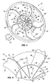
Fig. 1 is a perspective view of an axial-flow fan embodying the present invention. -
Fig. 2 is a partial end view of the fan ofFig. 1 . -
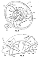
Fig. 3 is a perspective view of an axial-flow fan that is a second embodiment of the present invention. -
Fig. 4 is a partial end view of the fan ofFig. 3 . -
Fig. 5 is a perspective view of an axial-flow fan that is a third embodiment of the present invention. -
Fig. 6 is a partial end view of the fan ofFig. 5 . -
Fig. 7 is a perspective view of an axial-flow fan that is a fourth embodiment of the present invention. -
Fig. 8 is a partial end view of the fan ofFig. 7 . -
Fig. 9 is a perspective view of an axial-flow fan that is a fifth embodiment of the present invention. -
Fig. 10 is a partial end view of the fan ofFig. 9 . - Before any embodiments of the invention are explained in detail, it is to be understood that the invention is not limited in its application to the details of construction and the arrangement of components set forth in the following description or illustrated in the following drawings. The invention is capable of other embodiments and of being practiced or of being carried out in various ways. Also, it is to be understood that the phraseology and terminology used herein is for the purpose of description and should not be regarded as limiting.
-
Figs. 1 and 2 illustrate a first embodiment of an axial-flow fan 10 of the present invention. The illustratedfan 10 is used in an automobile for cooling the engine. However, thefan 10 can be used for other applications as well. Thefan 10 includes ahub 14 having a substantially closedend 18, and anopen end 22. Thehub 14 includes a cylindrical wall orcylindrical portion 26 that defines acentral axis 30 of thehub 14, about which thefan 10 rotates. Thehub 14 further includes a face portion orwall 34 that defines the substantially closedend 18. The illustratedface portion 34 includes anaperture 38 for receiving an output shaft of an electric motor (not shown) that drives thefan 10. - A plurality of blades 42 (individually labeled as 42a-e) extend radially outwardly from the
hub 14. Each blade 42 has ablade root 46, where the blade 42 couples to thecylindrical portion 26 of thehub 14, and ablade tip 50 spaced from theroot 46, and thereby spaced from thehub 14. Anoptional band 52 may be present that encircles thetips 50 of the blades. In other embodiments, theband 52 may be omitted. Afirst edge 54 of each blade 42 is the edge proximate theopen end 22 of thehub 14 and that interconnects theroot 46 and thetip 50. Thefirst edge 54 defines one of the leading edge and the trailing edge of the blade 42, and in the embodiment shown inFigs. 1 and 2 , defines the trailing edge of the blade 42. Thearrow 58 inFig. 1 illustrates the direction of airflow through thefan 10, while thearrow 62 illustrates the direction of fan rotation about thecentral axis 30. Asecond edge 66 of each blade 42 is the edge proximate the closedend 18 of thehub 14 and that interconnects theroot 46 and thetip 50. Thesecond edge 66 defines the other one of the leading edge and the trailing edge of the blade 42, and in the embodiment shown inFigs. 1 and 2 , defines the leading edge of the blade 42. - While the illustrated
fan 10 includes fiveblades 42a-e and a particular orientation of the blades 42, in which theopen end 22 of thehub 14 faces in a downstream direction with respect to the direction ofairflow 58, the invention is not limited to this blade configuration. For example, and as will be discussed below, different numbers of blades can be used. Additionally, different embodiments may be designed for different axial airflow directions, and,therefore different rotational directions of the fans, thereby changing the orientation of the blades. For example, in other embodiments the first edge of the blade might be the leading edge, while the second edge of the blade might be the trailing edge. - The
fan 10 further includes a plurality ofribs 70a-j coupled to thehub 14. Theribs 70a-j reinforce thehub 14 to reduce the deflection and stresses in thefan 10 that arise during operation. In the present invention, theribs 70a-j are positioned to reduce stresses in thehub 14 in a region proximate to the intersection with thefirst edge 54 of each blade 42, (i.e., the edge of the blade 42 proximate theopen end 22 of the hub 14). - Referring now to
Fig. 2 , afirst rib 70a is coupled to thehub 14 and is substantially aligned with a first plane P1 that intersects thecentral axis 30 and an intersection point of thefirst edge 54 of thefirst blade 42a with thecylindrical portion 26 of thehub 14. As used herein and in the appended claims, the phrase "substantially aligned", as used to describe the alignment of a rib with a plane, means that the radial centerline of the rib can be within plus or minus four degrees of the plane. As shown inFigs. 1 and 2 , the planes are perfectly aligned with the radial centerline of the ribs, but this need not be the case (see e.g.,Figs. 5 and 6 ). - The first plane P1 is angularly spaced from a reference plane P0 that intersects the
central axis 30 and an intersection point of thefirst edge 54 of thesecond blade 42b with thecylindrical portion 26 of thehub 14. An angular spacing between the first plane P1 and the reference plane P0 (in a clockwise direction from P1 to P0 as shown inFig. 2 ) defines one sector S of thefan 10. Asecond rib 70b is coupled to thehub 14 and is substantially aligned with a second plane P2 that intersects thecentral axis 30 and that is angularly positioned between the first plane P1 and the reference plane P0 at a location less than or equal to about (1/nR - 0.05) sectors from the first plane P1, in which nR equals the number of ribs 70 on thefan 10 divided by the number of blades 42 on thefan 10. In the illustrated embodiment of thefan 10 inFigs. 1 and 2 , thefan 10 includes tenribs 70a-j and fiveblades 42a-e. Accordingly, nR equals two, and the second plane P2 is angularly positioned at a location less than or equal to about 0.45 sectors from the first plane P1. More particularly, inFig. 2 , the second plane P2 is about 0.35 sectors from the first plane P1. - In some embodiments, the second plane P2 is angularly positioned between the first and the reference planes P1, P0 at a location less than or equal to about 0.30 sectors from the first plane P1. In yet other embodiments, the second plane P2 is angularly positioned between the first and the reference planes P1, P0 at a location between about 0.15 and about 0.35 sectors from the first plane P1. In further embodiments, the second plane P2 is also at a location greater than or equal to about 0.05 sectors from the first plane P1. The specific location of the second plane P2, and hence the
second rib 70b, can be optimized based upon particular design and/or operational characteristics of thefan 10. However, placing thesecond rib 70b within 0.45 sectors of the first plane P1, as shown inFig. 2 , helps provide targeted reinforcement to thehub 14 in the region proximate the intersection of thefirst edges 54 with thecylindrical portion 26 to reduce the deflection of thehub 14 and the resultant stresses in thehub 14. It can be noted that in some embodiments, the second plane P2 need not intersect thecentral axis 30, which would be the case if therib 70b were not oriented in a truly radial manner relative to thecylindrical portion 26 of thehub 14. However, therib 70b could still be positioned at the locations set forth above. - Referring again to
Fig. 1 , athird rib 70c is coupled to thehub 14 and is substantially aligned with the reference plane P0. Thefirst rib 70a, thesecond rib 70b, and thethird rib 70c together define a first 3-rib grouping pattern spanning one sector S of thehub 14. The 3-rib grouping pattern is repeated around the entire three hundred-sixty degrees of thehub 14 such that there is an identical 3-rib grouping pattern for each blade 42 of the fan. Specifically, theribs third rib 70c is part of the first 3-rib grouping pattern, but is also part of the second 3-rib grouping pattern. Likewise, theribs ribs ribs fan 10 around the three hundred-sixty degrees of the hub 14 (one sector S equals seventy-two degrees in the illustrated embodiment). The number of sectors S also correlates to the number of blades 42. - Of further significance is the number of ribs per sector S. There are five sectors S and ten
ribs 70a-j. Therefore, thefan 10 can be said to have two ribs per sector S. In this regard, theribs ribs fan 10 can also be said to have at least two ribs per blade. - As also seen in
Figs. 1 and 2 , theentire root 46 of thefirst blade 42a is positioned on a first side of the second plane P2 (and therefore of thesecond rib 70b), while theentire root 46 of thesecond blade 42b is on a second side of the second plane P2 (and therefore thesecond rib 70b) opposite the first side. Therefore, thesecond rib 70b is positioned angularly between the first andsecond blades cylindrical portion 26 where theroot 46 of either of the first orsecond blades hub 14. - Each
rib 70a-j includes a radially-extendingportion 74 coupled to theface portion 34 of thehub 14, and an axially-extendingportion 78 coupled to thecylindrical portion 26 of thehub 14. The configurations of theportions open end 22 of thehub 14 when thefan 10 is assembled with the motor. -
Figs. 3 and 4 illustrate a fan 10' that is a second embodiment of the invention and that is similar to thefan 10. Like parts have been given like reference numerals. The major distinction is that the fan 10' is designed to have theopen end 22 of thehub 14 on the upstream side of the airflow, as illustrated by thearrow 58. The direction of rotation of the fan 10' is reversed from that of thefan 10, as illustrated by thearrow 62. Furthermore, the orientation of the blades 42' is reversed such that the first edge 54 (the edge closest to theopen end 22 of the hub 14) of each blade 42' is now the leading edge, and the second edge 66 (the edge closest to the substantiallyclosed end 18 of the hub 14) of each blade 42' is now the trailing edge. However, the positioning of theribs 70a-j, the planes P1, P2, P0, and the determination of the sectors S remain the same, as dictated relative to thefirst edges 54 of the blades 42'. The positional relationships described above with respect to thefan 10 are the same for the fan 10'. Once again, the positioning of theribs 70a-j relative to thefirst edges 54 of the blades 42', as shown and described, provides improved deflection resistance and stress reduction over prior art arrangements. -
Figs. 5 and 6 illustrate afan 110 that is a third embodiment of the invention. Features of thefan 110 that are similar to thefans 10 and 10' have been given the same reference numerals of the one-hundred series. The orientation of thefan 110 is similar to that of the fan 10' in terms of the airflow direction (see arrow 158), the direction of rotation (see arrow 162), and the orientation of the blades 142 (individually labeled as 142a-c). Specifically, the first edge 154 (the edge closest to theopen end 122 of the hub 114) of each blade 142 is the leading edge, and the second edge 166 (the edge closest to the substantiallyclosed end 118 of the hub 114) of each blade 142 is the trailing edge. Thefan 110 includes only threeblades 142a-c. - Nine
ribs 170a-i are coupled to thehub 114. As shown inFig. 6 , afirst rib 170a is coupled to thehub 114 and is substantially aligned with a first plane P1 that intersects thecentral axis 130 and an intersection point of thefirst edge 154 of thefirst blade 142a with thecylindrical portion 126 of thehub 114. As used herein and in the appended claims, the phrase "substantially aligned", as used to describe the alignment of a rib with a plane, means that the radial centerline of the rib can be within plus or minus four degrees of the plane. - The first plane P1 is angularly spaced from a reference plane P0 that intersects the
central axis 130 and an intersection point of thefirst edge 154 of thesecond blade 142b with thecylindrical portion 126 of thehub 114. As shown inFig. 6 , the planes P1 and P0 are substantially aligned with the radial centerlines of theribs Fig. 6 ) defines one sector S. Asecond rib 170b is coupled to thehub 114 and is substantially aligned with a second plane P2 that intersects thecentral axis 130 and that is angularly positioned between the first plane P1 and the reference plane P0 at a location less than or equal to about (1/nR- 0.05) sectors from the first plane P1, in which nR equals three (i.e., nineribs 170a-i divided by threeblades 142a-c). Accordingly, the second plane P2 is angularly positioned at a location less than or equal to about 0.283 sectors from the first plane P1. More particularly, inFig. 6 , the second plane P2 is about 0.15 sectors from the first plane P1. - In some embodiments, the second plane P2 is angularly positioned between the first and the reference planes P1, P0 at a location between about 0.14 and about 0.21 sectors from the first plane P1. In further embodiments, the second plane P2 is also at a location greater than or equal to about 0.05 sectors from the first plane P1. The specific location of the second plane P2, and hence the
second rib 170b, can be optimized based upon particular design and/or operational characteristics of thefan 110. However, placing thesecond rib 170b within 0.283 sectors of the first plane P1 helps provide targeted reinforcement to thehub 114 in the region proximate the intersection of thefirst edges 154 with thecylindrical portion 126 to reduce the deflection of thehub 114 and the resultant stresses in thehub 114. It can be noted that in some embodiments, the second plane P2 need not intersect thecentral axis 130, which would be the case if therib 170b were not oriented in a truly radial manner relative to thecylindrical portion 126 of thehub 114. However, therib 170b could still be positioned at the locations set forth above. - With continued reference to
Fig. 6 , athird rib 170c is coupled to thehub 114 and is substantially aligned with a third plane P3 that intersects thecentral axis 130 and that is angularly positioned between the second and the reference planes P2, P0. In some embodiments, the second plane P2 and the third plane P3 are spaced from one another by at least about four degrees. InFig. 6 , the second and third planes P2 and P3 are shown spaced apart by about seventy degrees. In some embodiments, the third plane P3 may lie between an intersection of thesecond edge 166 of thesecond blade 142b with thehub 114 and an intersection of thefirst edge 154 of thesecond blade 142b with the hub 114 (i.e., within the span of theroot 146 of thesecond blade 142b; seeFIG. 8 ). Thefourth rib 170c provides additional reinforcement to thehub 114. - A
fourth rib 170d is coupled to thehub 114 and is substantially aligned with the reference plane P0. Thefirst rib 170a, thesecond rib 170b, thethird rib 170c, and thefourth rib 170d together define a first 4-rib grouping pattern spanning one sector S of thehub 114. The 4-rib grouping pattern is repeated around the entire three hundred-sixty degrees of thehub 114 such that there is an identical 4-rib grouping pattern for each blade 142 of the fan. Specifically, theribs fourth rib 170d is part of the first 4-rib grouping pattern, but is also part of the second 4-rib grouping pattern. Likewise, theribs - Of further significance is the number of ribs per sector S. There are three sectors S and nine
ribs 170a-i. Therefore, thefan 110 can be said to have three ribs per sector S. In this regard, theribs ribs fan 110 can also be said to have at least three ribs per blade. - As also seen in
Figs. 5 and 6 , theentire root 146 of thefirst blade 142a is positioned on a first side of the second plane P2 (and therefore of thesecond rib 170b), while theentire root 146 of thesecond blade 142b is on a second side of the second plane P2 (and therefore thesecond rib 170b) opposite the first side. Therefore, thesecond rib 170b is positioned angularly between the first andsecond blades cylindrical portion 126 where theroot 146 of either of the first orsecond blades hub 114. -
Figs. 7 and 8 illustrate afan 210 that is a fourth embodiment of the invention. Thefan 210 is similar to the fan 10' in terms of the number and orientation of the fan blades, the airflow direction, and the direction of rotation, and is similar to thefan 110 in terms of the positioning or grouping of the ribs. Features of thefan 210 that are similar to thefans 10' and 110 have been given the same reference numerals of the two-hundred series. - As shown in
Fig. 7 , fifteenribs 270a-o are coupled to thehub 214. As shown inFig. 8 , afirst rib 270a is coupled to thehub 214 and is substantially aligned with a first plane P1 that intersects thecentral axis 230 and an intersection point of thefirst edge 254 of thefirst blade 242a with thecylindrical portion 226 of thehub 214. As used herein and in the appended claims, the phrase "substantially aligned", as used to describe the alignment of a rib with a plane, means that the radial centerline of the rib can be within plus or minus four degrees of the plane. - The first plane P1 is angularly spaced from a reference plane P0 that intersects the
central axis 230 and an intersection point of thefirst edge 254 of thesecond blade 242b with thecylindrical portion 226 of thehub 214. As shown inFig. 8 , the planes P1 and P0 are substantially aligned with the radial centerlines of theribs Fig. 8 ) defines one sector S. Asecond rib 270b is coupled to thehub 214 and is substantially aligned with a second plane P2 that intersects thecentral axis 230 and that is angularly positioned between the first plane P1 and the reference plane P0 at a location less than or equal to about (1/nR- 0.05) sectors from the first plane P1, in which nR equals three (i.e., fifteenribs 270a-o divided by fiveblades 242a-e). Accordingly, the second plane P2 is angularly positioned at a location less than or equal to about 0.283 sectors from the first plane P1. More particularly, inFig. 8 , the second plane P2 is about 0.20 sectors from the first plane P1. - In some embodiments, the second plane P2 is angularly positioned between the first and the reference planes P1, P0 at a location between about 0..14 and about 0.21 sectors from the first plane P1. In further embodiments, the second plane P2 is also at a location greater than or equal to about 0.05 sectors from the first plane P1. The specific location of the second plane P2, and hence the
second rib 270b, can be optimized based upon particular design and/or operational characteristics of thefan 210. However, placing thesecond rib 270b within 0.283 sectors of the first plane P1 helps provide targeted reinforcement to thehub 214 in the region proximate the intersection of thefirst edges 254 with thecylindrical portion 226 to reduce the deflection of thehub 214 and the resultant stresses in thehub 214. It can be noted that in some embodiments, the second plane P2 need not intersect thecentral axis 230, which would be the case if therib 270b were not oriented in a truly radial manner relative to thecylindrical portion 226 of thehub 214. However, therib 270b could still be positioned at the locations set forth above. - A
third rib 270c is coupled to thehub 214 and is substantially aligned with a third plane P3 that intersects thecentral axis 230 and that is angularly positioned between the second and the reference planes P2, P0. In some embodiments, the second plane P2 and the third plane P3 are spaced from one another by at least about four degrees. InFig. 8 , the second and third planes P2 and P3 are shown spaced apart by about thirty degrees. As shown inFig. 8 , the third plane P3 lies between an intersection of thesecond edge 266 of thesecond blade 242b with thehub 214 and an intersection of thefirst edge 254 of thesecond blade 242b with the hub 214 (i.e., within the span of theroot 246 of thesecond blade 242b). As shown, the third plane P3 is about five to seven degrees away from the intersection of thesecond edge 266 of thesecond blade 242b with thehub 214. Thethird rib 270c provides additional reinforcement to thehub 214. - A
fourth rib 270d is coupled to thehub 214 and is substantially aligned with the reference plane P0. Thefirst rib 270a, thesecond rib 270b, thethird rib 270c, and thefourth rib 270d together define a first 4-rib grouping pattern spanning one sector S of thehub 214. The 4-rib grouping pattern is repeated around the entire three hundred-sixty degrees of thehub 214 such that there is an identical 4-rib grouping pattern for each blade 242 of the fan. Specifically, theribs fourth rib 270d is part of the first 4-rib grouping pattern, but is also part of the second 4-rib grouping pattern. Likewise, theribs ribs ribs - Of further significance is the number of ribs per sector S. There are five sectors S and fifteen
ribs 270a-o. Therefore, thefan 210 can be said to have three ribs per sector S. In this regard, theribs ribs fan 210 can also be said to have at least three ribs per blade. - As also seen in
Figs. 7 and 8 , theentire root 246 of thefirst blade 242a is positioned on a first side of the second plane P2 (and therefore of thesecond rib 270b), while theentire root 246 of thesecond blade 242b is on a second side of the second plane P2 (and therefore thesecond rib 270b) opposite the first side. Therefore, thesecond rib 270b is positioned angularly between the first andsecond blades cylindrical portion 226 where aroot 246 of either of the first orsecond blades hub 214. -
Figs. 9 and 10 illustrate afan 310 that is a fifth embodiment of the invention. Thefan 310 is similar to thefan 210, but it includes seven blades instead of five. Features of thefan 310 that are similar to thefan 210 have been given the same reference numerals of the three-hundred series. - As shown in
Fig. 9 , twenty-oneribs 370a-u are coupled to thehub 314. As shown inFig. 10 , afirst rib 370a is coupled to thehub 314 and is substantially aligned with a first plane P1 that intersects thecentral axis 330 and an intersection point of thefirst edge 354 of thefirst blade 342a with thecylindrical portion 326 of thehub 314. As used herein and in the appended claims, the phrase "substantially aligned", as used to describe the alignment of a rib with a plane, means that the radial centerline of the rib can be within plus or minus four degrees of the plane. - The first plane P1 is angularly spaced from a reference plane P0 that intersects the
central axis 330 and an intersection point of thefirst edge 354 of thesecond blade 342b with thecylindrical portion 326 of thehub 314. As shown inFig. 10 , the planes P1 and P0 are substantially aligned with the radial centerlines of theribs Fig. 10 ) defines one sector S. Asecond rib 370b is coupled to thehub 314 and is substantially aligned with a second plane P2 that intersects thecentral axis 330 and that is angularly positioned between the first plane P1 and the reference plane P0 at a location less than or equal to about (1/nR- 0.05) sectors from the first plane P1, in which nR equals three (i.e., twenty-oneribs 370a-u divided by sevenblades 342a-g). Accordingly, the second plane P2 is angularly positioned at a location less than or equal to about 0.283 sectors from the first plane P1. More particularly, inFigs. 9 and 10 , the second plane P2 is about 0..14 sectors from the first plane P1. - In some embodiments, the second plane P2 is angularly positioned between the first and the reference planes P1, P0 at a location between about 0.14 and about 0.21 sectors from the first plane P1. In further embodiments, the second plane P2 is also at a location greater than or equal to about 0.05 sectors from the first plane P1. The specific location of the second plane P2, and hence the
second rib 370b, can be optimized based upon particular design and/or operational characteristics of thefan 310. However, placing thesecond rib 370b within 0.283 sectors of the first plane P1 helps provide targeted reinforcement to thehub 314 in the region proximate the intersection of thefirst edges 354 with thecylindrical portion 326 to reduce the deflection of thehub 314 and the resultant stresses in thehub 314. It can be noted that in some embodiments, the second plane P2 need not intersect thecentral axis 330, which would be the case if therib 370b were not oriented in a truly radial manner relative to thecylindrical portion 326 of thehub 314. However, therib 370b could still be positioned at the locations set forth above. - A
third rib 370c is coupled to thehub 314 and is substantially aligned with a third plane P3 that intersects thecentral axis 330 and that is angularly positioned between the second plane P2 and the reference plane P0. In some embodiments, the second plane P2 and the third plane P3 are spaced from one another by at least about four degrees. InFig. 10 , the second and third planes P2 and P3 are shown spaced apart by about nine degrees. In some embodiments, the third plane P3 may lie between an intersection of thesecond edge 366 of thesecond blade 342b with thehub 314 and an intersection of thefirst edge 354 of thesecond blade 342b with the hub 314 (i.e., within the span of theroot 346 of thesecond blade 342b). Thethird rib 370c provides additional reinforcement to thehub 314. - A
fourth rib 370d is coupled to thehub 314 and is substantially aligned with the reference plane P0. Thefirst rib 370a, thesecond rib 370b, thethird rib 370c, and thefourth rib 370d together define a first 4-rib grouping pattern spanning one sector S of thehub 314. The 4-rib grouping pattern is repeated around the entire three hundred-sixty degrees of thehub 314 such that there is an identical 4-rib grouping pattern for each blade 342 of the fan. Specifically, theribs fourth rib 370d is part of the first 4-rib grouping pattern, but is also part of the second 4-rib grouping pattern. Likewise, theribs ribs ribs ribs ribs - Of further significance is the number of ribs per sector S. There are seven sectors S and twenty-one
ribs 370a-u. Therefore, thefan 310 can be said to have three ribs per sector S. In this regard, theribs ribs fan 310 can also be said to have at least three ribs per blade. - As also seen in
Figs. 9 and 10 , theentire root 346 of thefirst blade 342a is positioned on a first side of the second plane P2 (and therefore of thesecond rib 370b), while theentire root 346 of thesecond blade 342b is on a second side of the second plane P2 (and therefore thesecond rib 370b) opposite the first side. Therefore, thesecond rib 370b is positioned angularly between the first andsecond blades cylindrical portion 326 where theroot 346 of either of the first orsecond blades hub 314. - Although not shown in the drawings, other embodiments of the fan may include up to seven ribs per sector (i.e., 2 ≤ nR ≤ 7).
- Various features of the invention are set forth in the following claims.
Claims (21)
- An axial-flow fan (10; 110; 210; 310) comprising:a hub (14; 114; 214; 314) including an open end (22; 122; 222; 322) and a substantially closed end (18; 118; 218; 318), the hub defining a central axis (30; 130; 230; 330);a plurality of blades (42; 142; 242; 342) coupled to the hub and extending radially outwardly from the hub, each blade havinga root (46; 146; 246; 346) coupled to the hub,a tip (50; 150; 250; 350) spaced from the hub,a first edge (54; 154; 254; 354) proximate the open end of the hub and interconnecting the root and the tip, the first edge defining one of a leading edge and a trailing edge with respect to a rotational direction (62; 162; 262; 362) of the hub about the central axis, anda second edge (66; 166; 266; 366) proximate the substantially closed end of the hub and interconnecting the root and the tip, the second edge defining the other of the leading edge and the trailing edge; anda plurality of ribs (70; 170; 270; 370) coupled to the hub, includinga first rib (70a; 170a; 270a; 370a) substantially aligned with a first plane (P1) intersecting the central axis and an intersection of the first edge of a first of the plurality of blades with the hub, atthe root of the first blade, wherein an angular spacing between the first plane and a reference plane (P0) intersecting the central axis and an intersection of the first edge of a second of the plurality of blades with the hub, at the root of the second blade, defines one sector (S), anda second rib (70b; 170b; 270b; 370b) substantially aligned with a second plane (P2) angularly positioned between the first plane and the reference plane, at a location less than or equal to about (1/nR-0,05) sectors from the first plane in which nR equals the number of ribs divided by the number of blades;wherein the entire root of the first blade is positioned on a first side of the second plane, and wherein the entire root of the second blade is positioned on a second side of the second plane opposite the first side.
- The axial-flow fan (10; 110; 210; 310) of claim 1, wherein the second plane (P2) is at a location greater than or equal to about 0,05 sectors (S) from the first plane (P1).
- The axial-flow (10; 110; 210; 310) fan of claim 1, wherein nR equals two, and wherein the second plane (P2) is angularly positioned between the first plane (P1) and the reference plane (P0) at a location between about 0,15 and about 0,35 sectors (S) from the first plane (P1).
- The axial-flow fan (10; 110; 210; 310) of claim 1, wherein nR equals three, and wherein the second plane (p2) is angularly positioned between the first plane (P1) and the reference plane (P0) at a location between about 0,14 and about 0,21 sectors (S) from the first plane (P1).
- The axial-flow fan (10; 210; 310) of claim 1, wherein the first edge (54; 254; 354) of each blade (42; 242; 342) defines the trailing edge, and wherein the second edge (66; 266; 366) of each blade defines the leading edge.
- The axial-flow fan (110) of claim 1, wherein the first edge (154) of each blade (142) defines the leading edge, and wherein the second edge (166) of each blade defines the trailing edge.
- The axial-flow fan (10; 110; 210; 310) of claim 1, further comprising a third rib (70c; 170c; 270c), 370c) substantially aligned with the reference plane (P0).
- The axial-flow fan (10) of claim 7, wherein the first, second, and third ribs (70a, 70b, 70c) together define a first 3-rib grouping pattern, wherein the fan (10) further includes additional ribs (70d, 70e, 70f) defining additional 3-rib grouping patterns identical to the first 3-rib grouping pattern, and wherein the fan (10) has a total number of 3-rib grouping patterns equal to the number of blades (42) in the plurality of blades (42).
- The axial-flow fan (110; 210; 310) of claim 1, further comprising a third rib (170c; 270c; 370c) coupled to the hub (114; 214; 314) and substantially aligned with a third plane (P3) angularly positioned between the second plane (P2) and the reference plane (P0).
- The axial-flow fan of claim 9, further comprising a fourth rib (170d; 270d; 370d) substantially aligned with the reference plane (P0), wherein the first, second, third, and fourth ribs together define a first 4-rib grouping pattern, wherein the fan further includes additional ribs defining additional 4-rib grouping patterns identical to the first 4-rib grouping pattern, and wherein the fan has a total number of 4-rib grouping patterns equal to the number of blades in the plurality of blades.
- The axial-flow fan (10; 110; 210; 310) of claim 1, wherein the hub (14; 114; 214; 314) includes a face portion (34; 134; 234; 334) defining the closed end (18; 118; 218, 318) and a cylindrical portion (26; 126; 226; 326) coaxial with the central axis (30; 130; 230; 330), and wherein each rib (70; 170; 270, 370) includes
a radially-extending portion (74; 174; 274; 374) coupled to the face portion (34; 134; 234; 334), and
an axially-extending portion (78; 178; 278; 378) coupled to the cylindrical portion (26; 126; 226; 326). - The axial-flow fan (10; 210, 210; 310) of claim 1, wherein the number of blades (42; 142; 242; 342) in the plurality of blades equals the number of sectors (S) defined by the fan, and wherein the fan includes at least two ribs (70; 170; 270, 370) per sector (S).
- The axial-flow fan (10; 110; 210, 310) of claim 12, wherein the fan includes at least five blades (42; 142; 242; 342).
- The axial-flow fan (10) of claim 12, wherein nR equals two, and wherein the second plane (P2) is angularly positioned between the first plane (P1) and the reference plane (P0) at a location less than or equal to about 0,45 sectors (S) from the first plane (P1).
- The axial-flow fan (10; 110; 210, 310) of claim 1, wherein the number of blades (42; 142; 242; 342) in the plurality of blades equals the number of sectors (S) defined by the fan, and wherein the fan includes at least three ribs (70) per sector (S).
- The axial-flow fan (110, 210, 310) of claim 15, wherein the fan includes at least three blades (142; 242; 342).
- The axial-flow fan (110; 210, 310) of claim 15, wherein nR equals three, and wherein the second plane (P2) is angularly positioned between the first plane (P1) and the reference plane (P0) at a location less than or equal to about 0,283 sectors (S) from the first plane (P1).
- The axial-flow fan (10; 110; 210; 310) of claim 1, further comprising a third rib (70c; 170c; 270c; 370c) coupled to the hub (14; 114; 214; 314) and aligned with a third plane (P3) angularly positioned between the second plane (P2) and the reference plane (P0), the second and the third planes (P2, P3) being angularly spaced from one another by at least about four degrees (10; 110; 210; 310).
- The axial-flow fan (210) of claim 18, wherein the third plane (P3) lies between an intersection of the second edge (266) of the second of the plurality of blades (242) with the hub (214) and an intersection of the first edge (254) of the second of the plurality of blades (242) with the hub (214).
- The axial-flow fan (110; 210; 310) of claim 18, further comprising a fourth rib (170d; 270d; 370d) coupled to the hub (114; 214; 314) and aligned with the reference plane (P0).
- The axial-flow fan of claim 20, wherein the third plane (P3) and the reference plane (P0) are angularly spaced from one another by at least about 4 degrees.
Applications Claiming Priority (2)
| Application Number | Priority Date | Filing Date | Title |
|---|---|---|---|
| US12/779,680 US8091177B2 (en) | 2010-05-13 | 2010-05-13 | Axial-flow fan |
| PCT/US2011/034873 WO2011142998A1 (en) | 2010-05-13 | 2011-05-03 | Axial-flow fan |
Publications (2)
| Publication Number | Publication Date |
|---|---|
| EP2569544A1 EP2569544A1 (en) | 2013-03-20 |
| EP2569544B1 true EP2569544B1 (en) | 2015-07-08 |
Family
ID=44310945
Family Applications (1)
| Application Number | Title | Priority Date | Filing Date |
|---|---|---|---|
| EP11719941.4A Active EP2569544B1 (en) | 2010-05-13 | 2011-05-03 | Axial-flow fan |
Country Status (5)
| Country | Link |
|---|---|
| US (1) | US8091177B2 (en) |
| EP (1) | EP2569544B1 (en) |
| CN (1) | CN102639877B (en) |
| BR (1) | BR112012028799B1 (en) |
| WO (1) | WO2011142998A1 (en) |
Families Citing this family (16)
| Publication number | Priority date | Publication date | Assignee | Title |
|---|---|---|---|---|
| IT1404254B1 (en) * | 2011-01-25 | 2013-11-15 | Gate Srl | FAN, PARTICULARLY FOR A VENTILATION GROUP FOR A HEAT EXCHANGER OF A MOTOR VEHICLE |
| FR2989435B1 (en) * | 2012-04-16 | 2016-01-01 | Valeo Systemes Thermiques | AUTOMOTIVE FAN PROPELLER WITH SEGMENTED HUB STIFFENERS |
| WO2015056097A1 (en) | 2013-10-17 | 2015-04-23 | Imascap | Methods, systems and devices for pre-operatively planned glenoid placement guides and uses thereof |
| EP3068317B1 (en) | 2013-11-13 | 2018-08-22 | Tornier | Shoulder patient specific instrument |
| ITTO20140004U1 (en) * | 2014-01-10 | 2015-07-10 | Johnson Electric Asti S R L | FAN FOR A COOLING ELECTRIC FAN, PARTICULARLY FOR A HEAT EXCHANGER FOR A MOTOR VEHICLE |
| CN104343706B (en) * | 2014-10-23 | 2017-02-15 | 常州祥明智能动力股份有限公司 | Axial flow fan for brushless direct-current external rotor electric machine |
| US9926832B2 (en) * | 2015-04-24 | 2018-03-27 | Briggs & Stratton Corporation | Reverse fin cooling fan |
| US10167766B2 (en) | 2015-04-24 | 2019-01-01 | Briggs & Stratton Corporation | Reverse fin cooling fan |
| TWD182168S (en) * | 2016-07-27 | 2017-04-01 | 鑫賀精密電子(東莞)有限公司; | fan |
| US10808726B2 (en) * | 2017-04-24 | 2020-10-20 | Asia Vital Components Co., Ltd. | Fan structure |
| CN107131152B (en) * | 2017-06-23 | 2020-02-28 | 广东美的制冷设备有限公司 | Wind wheel, fan and refrigeration equipment |
| USD860427S1 (en) * | 2017-09-18 | 2019-09-17 | Horton, Inc. | Ring fan |
| JP6981226B2 (en) * | 2017-12-20 | 2021-12-15 | トヨタ自動車株式会社 | Blower fan |
| US11767761B2 (en) | 2018-08-02 | 2023-09-26 | Horton, Inc. | Low solidity vehicle cooling fan |
| TWI670421B (en) * | 2018-08-14 | 2019-09-01 | 建準電機工業股份有限公司 | Fan wheel |
| AT17059U1 (en) | 2020-02-11 | 2021-04-15 | Thomas Euler Rolle | Axial fan |
Family Cites Families (31)
| Publication number | Priority date | Publication date | Assignee | Title |
|---|---|---|---|---|
| US3622249A (en) | 1968-08-18 | 1971-11-23 | Aisin Seiki | Fan assembly |
| US3642382A (en) | 1969-05-11 | 1972-02-15 | Aisin Seiki | Fan assembly |
| US4169693A (en) | 1977-05-25 | 1979-10-02 | Eaton Corporation | Fluid coupling device and fan mounting arrangement |
| US4671739A (en) | 1980-07-11 | 1987-06-09 | Robert W. Read | One piece molded fan |
| US4358245A (en) | 1980-09-18 | 1982-11-09 | Bolt Beranek And Newman Inc. | Low noise fan |
| IT206701Z2 (en) * | 1985-08-02 | 1987-10-01 | Gate Spa | AXIAL FAN PARTICULARLY FOR VEHICLES |
| US5066196A (en) | 1988-04-21 | 1991-11-19 | Usui Kokusai Sangyo Kabushiki Kaisha | Engine-cooling fan made of synthetic resin |
| US4915588A (en) * | 1989-06-08 | 1990-04-10 | Siemens-Bendix Automotive Electronics Limited | Axial flow ring fan with fall off |
| DE4102161A1 (en) | 1991-01-25 | 1992-07-30 | Bosch Gmbh Robert | FAN WHEEL WITH A POT SHAPED HUB |
| DE4143383C2 (en) | 1991-07-03 | 1995-03-30 | Licentia Gmbh | Axial blower, in particular for cooling a condenser of an air conditioning system upstream of the radiator of a vehicle |
| US5244347A (en) | 1991-10-11 | 1993-09-14 | Siemens Automotive Limited | High efficiency, low noise, axial flow fan |
| DE69333845T2 (en) | 1992-05-15 | 2006-04-27 | Siemens Vdo Automotive Inc., Chatham | Axial |
| BR9300312A (en) | 1993-02-02 | 1993-07-27 | Alpina Equipamentos Ind Ltda | IMPROVEMENT IN FIBER REINFORCED PLASTIC PAS |
| DE4445671B4 (en) | 1994-12-21 | 2005-03-24 | Behr Gmbh & Co. Kg | Axial fan for a radiator of a motor vehicle engine |
| US5577888A (en) | 1995-06-23 | 1996-11-26 | Siemens Electric Limited | High efficiency, low-noise, axial fan assembly |
| US5871335A (en) | 1995-10-31 | 1999-02-16 | Siemens Electric Limited | Twist-lock attachment system for a cooling fan and motor |
| US5769607A (en) * | 1997-02-04 | 1998-06-23 | Itt Automotive Electrical Systems, Inc. | High-pumping, high-efficiency fan with forward-swept blades |
| US5967764A (en) | 1997-08-08 | 1999-10-19 | Bosch Automotive Systems Corporation | Axial fan with self-cooled motor |
| FR2781843B1 (en) | 1998-07-28 | 2000-10-20 | Valeo Thermique Moteur Sa | OPTIMIZED COMPACT FAN PROPELLER |
| DE19929978B4 (en) | 1999-06-30 | 2006-02-09 | Behr Gmbh & Co. Kg | Fan with axial blades |
| US6375427B1 (en) | 2000-04-14 | 2002-04-23 | Borgwarner Inc. | Engine cooling fan having supporting vanes |
| EP1337758B1 (en) * | 2000-11-08 | 2006-02-08 | Robert Bosch Corporation | High-efficiency, inflow-adapted, axial-flow fan |
| JP3998456B2 (en) | 2001-11-05 | 2007-10-24 | アイシン化工株式会社 | cooling fan |
| FR2848619B1 (en) | 2002-12-13 | 2006-03-17 | Valeo Systemes Dessuyage | ENGINE COOLING PROPELLER |
| US7244110B2 (en) | 2003-09-30 | 2007-07-17 | Valeo Electrical Systems, Inc. | Fan hub assembly for effective motor cooling |
| WO2005098256A2 (en) | 2004-04-01 | 2005-10-20 | Behr America, Inc. | Viscous fluid clutch assembly |
| US20070199784A1 (en) | 2004-04-01 | 2007-08-30 | General Motors Corporation | Clutch Assembly |
| CN100389267C (en) * | 2004-07-06 | 2008-05-21 | 鸿富锦精密工业(深圳)有限公司 | Fan blade structure |
| DE602007002588D1 (en) * | 2006-05-31 | 2009-11-12 | Bosch Gmbh Robert | Axialgebläseanordnung |
| US8672649B2 (en) | 2007-10-10 | 2014-03-18 | Delta T Corporation | Ceiling fan system with brushless motor |
| CN201159188Y (en) * | 2008-01-04 | 2008-12-03 | 台达电子工业股份有限公司 | Fan and its impeller |
-
2010
- 2010-05-13 US US12/779,680 patent/US8091177B2/en active Active
-
2011
- 2011-05-03 EP EP11719941.4A patent/EP2569544B1/en active Active
- 2011-05-03 CN CN201180004754.9A patent/CN102639877B/en active Active
- 2011-05-03 BR BR112012028799-0A patent/BR112012028799B1/en active IP Right Grant
- 2011-05-03 WO PCT/US2011/034873 patent/WO2011142998A1/en not_active Ceased
Also Published As
| Publication number | Publication date |
|---|---|
| CN102639877B (en) | 2015-09-09 |
| BR112012028799B1 (en) | 2020-07-21 |
| US20110280729A1 (en) | 2011-11-17 |
| US8091177B2 (en) | 2012-01-10 |
| EP2569544A1 (en) | 2013-03-20 |
| CN102639877A (en) | 2012-08-15 |
| WO2011142998A1 (en) | 2011-11-17 |
| BR112012028799A2 (en) | 2016-07-26 |
Similar Documents
| Publication | Publication Date | Title |
|---|---|---|
| EP2569544A1 (en) | Axial-flow fan | |
| US8342808B2 (en) | Cooling fan | |
| EP1862675B1 (en) | Axial fan assembly | |
| CN212407116U (en) | Fan wheel and cooling fan with same | |
| US20030235502A1 (en) | Segmented composite impeller/propeller arrangement and manufacturing method | |
| US20080131268A1 (en) | Turbomachine with variable guide/stator blades | |
| CN107869483A (en) | Aerofoil fan and the outdoor unit for having used the aerofoil fan | |
| CN101981290B (en) | Fan shroud with modular vane sets | |
| EP4150218B1 (en) | Banded cooling fan band having knit-line strength improvement | |
| CN106438471B (en) | Axial-flow windwheel and air conditioner | |
| US20080078340A1 (en) | Fan Module motor mont arms with shape optimization | |
| US11898569B2 (en) | Banded cooling fan band having knit-line strength improvement | |
| JP6192419B2 (en) | Propeller fan | |
| US7014425B2 (en) | Low pressure fan with Y-shaped blades | |
| US3107897A (en) | Gas turbine nozzle and vane assembly | |
| JP4679074B2 (en) | cooling fan | |
| JP2007063989A (en) | Cooling fan | |
| US20230130411A1 (en) | Banded Cooling Fan Band having Knit-Line Strength Improvement | |
| JP2011074763A (en) | Impeller and blower having the same | |
| CN112539188A (en) | Improved rotor fan | |
| JP2024131053A (en) | Cooling fan and fan device | |
| US20260063144A1 (en) | Axial fan and housing assembly and methods of use thereof | |
| EP4012191B1 (en) | Axial flow fan, and refrigeration cycle device | |
| CN109312661B (en) | Impeller for supercharger | |
| KR100897133B1 (en) | Cooling fan |
Legal Events
| Date | Code | Title | Description |
|---|---|---|---|
| PUAI | Public reference made under article 153(3) epc to a published international application that has entered the european phase |
Free format text: ORIGINAL CODE: 0009012 |
|
| 17P | Request for examination filed |
Effective date: 20121213 |
|
| AK | Designated contracting states |
Kind code of ref document: A1 Designated state(s): AL AT BE BG CH CY CZ DE DK EE ES FI FR GB GR HR HU IE IS IT LI LT LU LV MC MK MT NL NO PL PT RO RS SE SI SK SM TR |
|
| DAX | Request for extension of the european patent (deleted) | ||
| GRAP | Despatch of communication of intention to grant a patent |
Free format text: ORIGINAL CODE: EPIDOSNIGR1 |
|
| INTG | Intention to grant announced |
Effective date: 20150108 |
|
| GRAS | Grant fee paid |
Free format text: ORIGINAL CODE: EPIDOSNIGR3 |
|
| GRAA | (expected) grant |
Free format text: ORIGINAL CODE: 0009210 |
|
| AK | Designated contracting states |
Kind code of ref document: B1 Designated state(s): AL AT BE BG CH CY CZ DE DK EE ES FI FR GB GR HR HU IE IS IT LI LT LU LV MC MK MT NL NO PL PT RO RS SE SI SK SM TR |
|
| REG | Reference to a national code |
Ref country code: GB Ref legal event code: FG4D |
|
| REG | Reference to a national code |
Ref country code: AT Ref legal event code: REF Ref document number: 735642 Country of ref document: AT Kind code of ref document: T Effective date: 20150715 Ref country code: CH Ref legal event code: EP |
|
| REG | Reference to a national code |
Ref country code: IE Ref legal event code: FG4D |
|
| REG | Reference to a national code |
Ref country code: DE Ref legal event code: R096 Ref document number: 602011017671 Country of ref document: DE |
|
| REG | Reference to a national code |
Ref country code: AT Ref legal event code: MK05 Ref document number: 735642 Country of ref document: AT Kind code of ref document: T Effective date: 20150708 |
|
| REG | Reference to a national code |
Ref country code: NL Ref legal event code: MP Effective date: 20150708 |
|
| REG | Reference to a national code |
Ref country code: LT Ref legal event code: MG4D |
|
| PG25 | Lapsed in a contracting state [announced via postgrant information from national office to epo] |
Ref country code: GR Free format text: LAPSE BECAUSE OF FAILURE TO SUBMIT A TRANSLATION OF THE DESCRIPTION OR TO PAY THE FEE WITHIN THE PRESCRIBED TIME-LIMIT Effective date: 20151009 Ref country code: LT Free format text: LAPSE BECAUSE OF FAILURE TO SUBMIT A TRANSLATION OF THE DESCRIPTION OR TO PAY THE FEE WITHIN THE PRESCRIBED TIME-LIMIT Effective date: 20150708 Ref country code: LV Free format text: LAPSE BECAUSE OF FAILURE TO SUBMIT A TRANSLATION OF THE DESCRIPTION OR TO PAY THE FEE WITHIN THE PRESCRIBED TIME-LIMIT Effective date: 20150708 Ref country code: FI Free format text: LAPSE BECAUSE OF FAILURE TO SUBMIT A TRANSLATION OF THE DESCRIPTION OR TO PAY THE FEE WITHIN THE PRESCRIBED TIME-LIMIT Effective date: 20150708 Ref country code: NO Free format text: LAPSE BECAUSE OF FAILURE TO SUBMIT A TRANSLATION OF THE DESCRIPTION OR TO PAY THE FEE WITHIN THE PRESCRIBED TIME-LIMIT Effective date: 20151008 |
|
| PG25 | Lapsed in a contracting state [announced via postgrant information from national office to epo] |
Ref country code: IS Free format text: LAPSE BECAUSE OF FAILURE TO SUBMIT A TRANSLATION OF THE DESCRIPTION OR TO PAY THE FEE WITHIN THE PRESCRIBED TIME-LIMIT Effective date: 20151108 Ref country code: PL Free format text: LAPSE BECAUSE OF FAILURE TO SUBMIT A TRANSLATION OF THE DESCRIPTION OR TO PAY THE FEE WITHIN THE PRESCRIBED TIME-LIMIT Effective date: 20150708 Ref country code: HR Free format text: LAPSE BECAUSE OF FAILURE TO SUBMIT A TRANSLATION OF THE DESCRIPTION OR TO PAY THE FEE WITHIN THE PRESCRIBED TIME-LIMIT Effective date: 20150708 Ref country code: SE Free format text: LAPSE BECAUSE OF FAILURE TO SUBMIT A TRANSLATION OF THE DESCRIPTION OR TO PAY THE FEE WITHIN THE PRESCRIBED TIME-LIMIT Effective date: 20150708 Ref country code: PT Free format text: LAPSE BECAUSE OF FAILURE TO SUBMIT A TRANSLATION OF THE DESCRIPTION OR TO PAY THE FEE WITHIN THE PRESCRIBED TIME-LIMIT Effective date: 20151109 Ref country code: ES Free format text: LAPSE BECAUSE OF FAILURE TO SUBMIT A TRANSLATION OF THE DESCRIPTION OR TO PAY THE FEE WITHIN THE PRESCRIBED TIME-LIMIT Effective date: 20150708 Ref country code: RS Free format text: LAPSE BECAUSE OF FAILURE TO SUBMIT A TRANSLATION OF THE DESCRIPTION OR TO PAY THE FEE WITHIN THE PRESCRIBED TIME-LIMIT Effective date: 20150708 Ref country code: AT Free format text: LAPSE BECAUSE OF FAILURE TO SUBMIT A TRANSLATION OF THE DESCRIPTION OR TO PAY THE FEE WITHIN THE PRESCRIBED TIME-LIMIT Effective date: 20150708 |
|
| REG | Reference to a national code |
Ref country code: DE Ref legal event code: R097 Ref document number: 602011017671 Country of ref document: DE |
|
| PG25 | Lapsed in a contracting state [announced via postgrant information from national office to epo] |
Ref country code: CZ Free format text: LAPSE BECAUSE OF FAILURE TO SUBMIT A TRANSLATION OF THE DESCRIPTION OR TO PAY THE FEE WITHIN THE PRESCRIBED TIME-LIMIT Effective date: 20150708 Ref country code: EE Free format text: LAPSE BECAUSE OF FAILURE TO SUBMIT A TRANSLATION OF THE DESCRIPTION OR TO PAY THE FEE WITHIN THE PRESCRIBED TIME-LIMIT Effective date: 20150708 Ref country code: SK Free format text: LAPSE BECAUSE OF FAILURE TO SUBMIT A TRANSLATION OF THE DESCRIPTION OR TO PAY THE FEE WITHIN THE PRESCRIBED TIME-LIMIT Effective date: 20150708 Ref country code: IT Free format text: LAPSE BECAUSE OF FAILURE TO SUBMIT A TRANSLATION OF THE DESCRIPTION OR TO PAY THE FEE WITHIN THE PRESCRIBED TIME-LIMIT Effective date: 20150708 Ref country code: DK Free format text: LAPSE BECAUSE OF FAILURE TO SUBMIT A TRANSLATION OF THE DESCRIPTION OR TO PAY THE FEE WITHIN THE PRESCRIBED TIME-LIMIT Effective date: 20150708 |
|
| PLBE | No opposition filed within time limit |
Free format text: ORIGINAL CODE: 0009261 |
|
| STAA | Information on the status of an ep patent application or granted ep patent |
Free format text: STATUS: NO OPPOSITION FILED WITHIN TIME LIMIT |
|
| REG | Reference to a national code |
Ref country code: FR Ref legal event code: PLFP Year of fee payment: 6 |
|
| PG25 | Lapsed in a contracting state [announced via postgrant information from national office to epo] |
Ref country code: RO Free format text: LAPSE BECAUSE OF FAILURE TO SUBMIT A TRANSLATION OF THE DESCRIPTION OR TO PAY THE FEE WITHIN THE PRESCRIBED TIME-LIMIT Effective date: 20150708 |
|
| 26N | No opposition filed |
Effective date: 20160411 |
|
| PG25 | Lapsed in a contracting state [announced via postgrant information from national office to epo] |
Ref country code: BE Free format text: LAPSE BECAUSE OF NON-PAYMENT OF DUE FEES Effective date: 20160531 Ref country code: SI Free format text: LAPSE BECAUSE OF FAILURE TO SUBMIT A TRANSLATION OF THE DESCRIPTION OR TO PAY THE FEE WITHIN THE PRESCRIBED TIME-LIMIT Effective date: 20150708 |
|
| PG25 | Lapsed in a contracting state [announced via postgrant information from national office to epo] |
Ref country code: LU Free format text: LAPSE BECAUSE OF FAILURE TO SUBMIT A TRANSLATION OF THE DESCRIPTION OR TO PAY THE FEE WITHIN THE PRESCRIBED TIME-LIMIT Effective date: 20160503 Ref country code: BE Free format text: LAPSE BECAUSE OF FAILURE TO SUBMIT A TRANSLATION OF THE DESCRIPTION OR TO PAY THE FEE WITHIN THE PRESCRIBED TIME-LIMIT Effective date: 20150708 |
|
| REG | Reference to a national code |
Ref country code: CH Ref legal event code: PL |
|
| PG25 | Lapsed in a contracting state [announced via postgrant information from national office to epo] |
Ref country code: LI Free format text: LAPSE BECAUSE OF NON-PAYMENT OF DUE FEES Effective date: 20160531 Ref country code: CH Free format text: LAPSE BECAUSE OF NON-PAYMENT OF DUE FEES Effective date: 20160531 |
|
| REG | Reference to a national code |
Ref country code: IE Ref legal event code: MM4A |
|
| REG | Reference to a national code |
Ref country code: FR Ref legal event code: PLFP Year of fee payment: 7 |
|
| PG25 | Lapsed in a contracting state [announced via postgrant information from national office to epo] |
Ref country code: IE Free format text: LAPSE BECAUSE OF NON-PAYMENT OF DUE FEES Effective date: 20160503 |
|
| PG25 | Lapsed in a contracting state [announced via postgrant information from national office to epo] |
Ref country code: NL Free format text: LAPSE BECAUSE OF FAILURE TO SUBMIT A TRANSLATION OF THE DESCRIPTION OR TO PAY THE FEE WITHIN THE PRESCRIBED TIME-LIMIT Effective date: 20150708 |
|
| REG | Reference to a national code |
Ref country code: FR Ref legal event code: PLFP Year of fee payment: 8 |
|
| PG25 | Lapsed in a contracting state [announced via postgrant information from national office to epo] |
Ref country code: CY Free format text: LAPSE BECAUSE OF FAILURE TO SUBMIT A TRANSLATION OF THE DESCRIPTION OR TO PAY THE FEE WITHIN THE PRESCRIBED TIME-LIMIT Effective date: 20150708 Ref country code: HU Free format text: LAPSE BECAUSE OF FAILURE TO SUBMIT A TRANSLATION OF THE DESCRIPTION OR TO PAY THE FEE WITHIN THE PRESCRIBED TIME-LIMIT; INVALID AB INITIO Effective date: 20110503 Ref country code: SM Free format text: LAPSE BECAUSE OF FAILURE TO SUBMIT A TRANSLATION OF THE DESCRIPTION OR TO PAY THE FEE WITHIN THE PRESCRIBED TIME-LIMIT Effective date: 20150708 |
|
| PG25 | Lapsed in a contracting state [announced via postgrant information from national office to epo] |
Ref country code: MC Free format text: LAPSE BECAUSE OF FAILURE TO SUBMIT A TRANSLATION OF THE DESCRIPTION OR TO PAY THE FEE WITHIN THE PRESCRIBED TIME-LIMIT Effective date: 20150708 Ref country code: MT Free format text: LAPSE BECAUSE OF NON-PAYMENT OF DUE FEES Effective date: 20160531 Ref country code: MK Free format text: LAPSE BECAUSE OF FAILURE TO SUBMIT A TRANSLATION OF THE DESCRIPTION OR TO PAY THE FEE WITHIN THE PRESCRIBED TIME-LIMIT Effective date: 20150708 Ref country code: TR Free format text: LAPSE BECAUSE OF FAILURE TO SUBMIT A TRANSLATION OF THE DESCRIPTION OR TO PAY THE FEE WITHIN THE PRESCRIBED TIME-LIMIT Effective date: 20150708 |
|
| PG25 | Lapsed in a contracting state [announced via postgrant information from national office to epo] |
Ref country code: BG Free format text: LAPSE BECAUSE OF FAILURE TO SUBMIT A TRANSLATION OF THE DESCRIPTION OR TO PAY THE FEE WITHIN THE PRESCRIBED TIME-LIMIT Effective date: 20150708 |
|
| PG25 | Lapsed in a contracting state [announced via postgrant information from national office to epo] |
Ref country code: AL Free format text: LAPSE BECAUSE OF FAILURE TO SUBMIT A TRANSLATION OF THE DESCRIPTION OR TO PAY THE FEE WITHIN THE PRESCRIBED TIME-LIMIT Effective date: 20150708 |
|
| PGFP | Annual fee paid to national office [announced via postgrant information from national office to epo] |
Ref country code: FR Payment date: 20190521 Year of fee payment: 9 |
|
| PGFP | Annual fee paid to national office [announced via postgrant information from national office to epo] |
Ref country code: GB Payment date: 20190523 Year of fee payment: 9 |
|
| GBPC | Gb: european patent ceased through non-payment of renewal fee |
Effective date: 20200503 |
|
| PG25 | Lapsed in a contracting state [announced via postgrant information from national office to epo] |
Ref country code: FR Free format text: LAPSE BECAUSE OF NON-PAYMENT OF DUE FEES Effective date: 20200531 Ref country code: GB Free format text: LAPSE BECAUSE OF NON-PAYMENT OF DUE FEES Effective date: 20200503 |
|
| PGFP | Annual fee paid to national office [announced via postgrant information from national office to epo] |
Ref country code: DE Payment date: 20250716 Year of fee payment: 15 |