EP2568718A2 - Audio apparatus - Google Patents
Audio apparatus Download PDFInfo
- Publication number
- EP2568718A2 EP2568718A2 EP12006272A EP12006272A EP2568718A2 EP 2568718 A2 EP2568718 A2 EP 2568718A2 EP 12006272 A EP12006272 A EP 12006272A EP 12006272 A EP12006272 A EP 12006272A EP 2568718 A2 EP2568718 A2 EP 2568718A2
- Authority
- EP
- European Patent Office
- Prior art keywords
- open
- speaker
- wave
- space
- stationary wave
- Prior art date
- Legal status (The legal status is an assumption and is not a legal conclusion. Google has not performed a legal analysis and makes no representation as to the accuracy of the status listed.)
- Granted
Links
Images





Classifications
-
- H—ELECTRICITY
- H04—ELECTRIC COMMUNICATION TECHNIQUE
- H04R—LOUDSPEAKERS, MICROPHONES, GRAMOPHONE PICK-UPS OR LIKE ACOUSTIC ELECTROMECHANICAL TRANSDUCERS; ELECTRIC HEARING AIDS; PUBLIC ADDRESS SYSTEMS
- H04R1/00—Details of transducers, loudspeakers or microphones
- H04R1/20—Arrangements for obtaining desired frequency or directional characteristics
- H04R1/22—Arrangements for obtaining desired frequency or directional characteristics for obtaining desired frequency characteristic only
- H04R1/28—Transducer mountings or enclosures modified by provision of mechanical or acoustic impedances, e.g. resonator, damping means
- H04R1/2869—Reduction of undesired resonances, i.e. standing waves within enclosure, or of undesired vibrations, i.e. of the enclosure itself
- H04R1/2873—Reduction of undesired resonances, i.e. standing waves within enclosure, or of undesired vibrations, i.e. of the enclosure itself for loudspeaker transducers
-
- H—ELECTRICITY
- H04—ELECTRIC COMMUNICATION TECHNIQUE
- H04R—LOUDSPEAKERS, MICROPHONES, GRAMOPHONE PICK-UPS OR LIKE ACOUSTIC ELECTROMECHANICAL TRANSDUCERS; ELECTRIC HEARING AIDS; PUBLIC ADDRESS SYSTEMS
- H04R1/00—Details of transducers, loudspeakers or microphones
- H04R1/20—Arrangements for obtaining desired frequency or directional characteristics
- H04R1/22—Arrangements for obtaining desired frequency or directional characteristics for obtaining desired frequency characteristic only
- H04R1/28—Transducer mountings or enclosures modified by provision of mechanical or acoustic impedances, e.g. resonator, damping means
- H04R1/2807—Enclosures comprising vibrating or resonating arrangements
- H04R1/2815—Enclosures comprising vibrating or resonating arrangements of the bass reflex type
- H04R1/2819—Enclosures comprising vibrating or resonating arrangements of the bass reflex type for loudspeaker transducers
-
- H—ELECTRICITY
- H04—ELECTRIC COMMUNICATION TECHNIQUE
- H04R—LOUDSPEAKERS, MICROPHONES, GRAMOPHONE PICK-UPS OR LIKE ACOUSTIC ELECTROMECHANICAL TRANSDUCERS; ELECTRIC HEARING AIDS; PUBLIC ADDRESS SYSTEMS
- H04R2499/00—Aspects covered by H04R or H04S not otherwise provided for in their subgroups
- H04R2499/10—General applications
- H04R2499/13—Acoustic transducers and sound field adaptation in vehicles
Definitions
- the present invention relates to a technology for suppressing a stationary wave using resonance of a pipe.
- Japanese Patents Nos. 2606447 and 3763682 , and JP-A-2008-131199 technologies for suppressing the stationary wave in a speaker which is one example of the audio appliance are disclosed.
- the speaker apparatus disclosed in Japanese Patent No. 2606447 includes a speaker unit, a cabinet built equipped with the speaker unit, and a Helmholtz resonator installed in the cabinet.
- a neck length L and a cavity volume V of the speaker apparatus are designed so that the Helmholtz resonator is resonated at the same frequency as a stationary wave which is generated in the cabinet.
- the Helmholtz resonator develops a resonance phenomenon, and thus the stationary wave is attenuated by the resonance phenomenon.
- the speaker apparatus disclosed in Japanese Patent No. 3763682 includes a speaker unit, a cabinet equipped with the speaker unit, and an audio pipe (open pipe) having an open end and a closed end.
- the audio pipe of the speaker apparatus has a pipe length L of 1/4 times as much as the minimum resonance mode of the stationary wave which is generated in the cabinet.
- the audio pipe is accommodated in the cabinet in a posture in which a position of the open end is close to a position of a loop of sound pressure (node of particle velocity) of the stationary wave in the cabinet.
- a resonance wave is generated in the audio pipe.
- the resonance wave has a node of the sound pressure (loop of particle velocity) at the open end of the audio pipe, and a loop of the sound pressure (node of particle velocity) at the closed end.
- JP-A-2008-131199 also discloses a technology similar to that disclosed in Japanese Patent No. 3763682 .
- Japanese Patent No. 3763682 and JP-A-2008-131199 matches the position of the loop of the stationary wave in the space with the position of the node of the resonance wave in the audio pipe, and the distribution of the sound pressure in the space is relieved at the position, thereby reducing the stationary wave. Accordingly, even though the audio pipe accommodated in the space is not the open pipe, but the open pipe (pipe having both open sides), the same effect as the technology of Japanese Patent No. 3763682 and JP-A-2008-131199 can be achieved even by disposing the open pipe in a manner that the position of the loop of the stationary wave in the space is matched with the position of the node of the resonance wave in the open pipe. However, this technology is not yet put to practical use.
- the present invention has been made to solve the above problems, and an object of the present invention is to provide a technique for suppressing a stationary wave, which is generated in a space, by use of pipe resonance of an open pipe.
- An aspect of the present invention provides an audio apparatus, including: a housing including a space which is enclosed at least one pair of opposite surfaces; and an open pipe including a first open end and a second open end positioned in the space, wherein the open pipe has a pipe length of integral multiple of a substantially half wavelength of a stationary wave which is generated in the space, and the first open end of the open pipe is disposed at a position of a substantial loop of the stationary wave which is generated in the space.
- the audio apparatus may be configured so that the second open end of the open pipe is disposed at a position of a substantial node of the stationary wave which is generated in the space.
- the audio apparatus may be configured so that the first and second open ends of the open pipe are respectively disposed at positions which are spaced apart from each other by a length of odd multiple of a substantially quarter wavelength of the stationary wave along an opposite direction of the one pair of opposite surfaces.
- the audio apparatus may be configured so that the second open end of the open pipe is disposed at a position of a substantial loop of the stationary wave which is generated in the space.
- the audio apparatus may be configured so that at least one of the first and second open ends of the open pipe is wholly or partially covered with an air-permeable sound absorbing material.
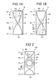
- Fig. 1A is a front view of a speaker 9 which is an audio apparatus according to a first embodiment of the present invention.
- the speaker 9 includes a cabinet 1, a speaker unit 2 fixed to an outside of the cabinet 1, and an open pipe 10 accommodated in a space S of the cabinet 1.
- the cabinet 1 is a member serving as a housing of the speaker 9.
- the cabinet 1 is formed in a hollow rectangular cubic shape enclosed by wall surfaces 4U and 4D opposite to each other in upward and downward directions, wall surfaces 4F and 4B opposite to each other in back and forth directions, and wall surfaces 4L and 4R opposite to each other in right and left directions.
- the speaker unit 2 is an apparatus serving as a sound generating source in the speaker 9.
- the speaker unit 2 is built in a substantially center portion of the wall surface 4U of the cabinet 1, with a sound-emission surface facing an outside.
- the speaker unit 2 is input with an electric signal from an audio apparatus (not illustrated).
- the speaker unit 2 irradiates the electric signal as a sound wave.
- the open pipe 10 is a member for reducing the stationary waves SW k .
- the open pipe 10 has a pipe length of a substantially half wavelength of the lowest order one (first-order stationary wave SW 1 in the example of Fig. 1A ) of the stationary waves SW k to be suppressed.
- the term "substantially" or its similar term in the meaning of the substantially half wavelength of the lowest order one of the stationary waves SW k to be suppressed indicates a variation within ⁇ 20% of the half wavelength, and the same applies to the following embodiments.
- the open pipe 10 is formed in a J-shape which is bent at a right angle at two points in the halfway leading from one open end 11 to the other open end 12.
- condition 'a1' is one condition in which one open end 11 and the other open end 12 are respectively disposed at positions of a substantial loop LP and a substantial node ND of a sound pressure of the lowest order one of the stationary waves SW k to be suppressed in the space S; and condition 'b1' is another condition in which one open end 11 and the other open end 12 are respectively disposed at each position spaced apart by about quarter wavelength of the stationary waves SW k in an opposite direction of two opposite surfaces of the wall surfaces 4U and 4D in the space S.
- the term "substantial” or its similar term in the meaning of the position of the substantial loop LP indicates a variation within ⁇ 10% from the position of the loop of the wavelength of the stationary wave. Further, the term “substantial” or its similar term in the meaning of the position of the substantial node ND indicates a variation within ⁇ 10% from the position of the node of the wavelength of the stationary wave. The same applies to the following embodiments with regard to the range of the variation.
- the open end 11 is disposed at the position of the loop LP 1-1 , which is on the side of the wall surface 4U, of two loops LP 1-1 and LP 1-2 of the first-order stationary wave SW 1 , and the open end 12 is disposed at the position of the node ND 1-1 between the two loops LP 1-1 and LP 1-2 .
- the open end 11 may be disposed at the position of the loop LP 1-2 on the side of wall surface 4D, and the open end 12 may be disposed at the position of the node ND 1-1 .
- an open pipe 20 having a pipe length of approximately half wavelength of the second stationary wave SW 2 may be accommodated in the space S in the posture which satisfies the above-described conditions 'a1' and 'b1'.
- the open pipe 20 is accommodated in the space S in the above posture, it is also possible to reduce the first-order or more stationary wave SW k in the space S.
- a first verification will be explained.
- a test sound signal ST e.g., white noise
- the inventors calculated a frequency response R-9 which is a spectrum difference between the input signal ST and a measured signal SM by means of simulation.
- a frequency response R-9' which is a spectrum difference between the input signal ST and a measured signal SM by means of simulation.
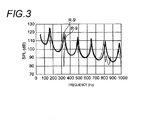
- Fig. 3 illustrates the frequency responses R-9 and R-9' at the same frequency axis.
- a peak appears in the proximity of 160 Hz, 320 Hz, 480 Hz, 650 Hz, 820 Hz, and 960 Hz in any frequency responses R-9 and R-9'.
- amplitude of the peak in the proximity of 650 Hz is substantially equal to that in the frequency response R-9', but amplitude of the peaks in the proximity of 160 Hz, 320 Hz, 480 Hz, 820 Hz and 970 Hz is smaller than that in the frequency response R-9'.
- the peaks in the proximity of 160 Hz, 320 Hz, 480 Hz, 820 Hz and 970 Hz are split.
- the invertors made an assumption about that suppression of the stationary waves SW 1 , SW 2 , SW 3 , SW 5 and SW 6 by the speaker 9 which is the example of Fig. 1A is caused by the following reason, except for the fourth-order stationary wave SW 4 , on the basis of the verified result of the first verification.
- the open end 11 of the open pipe 10 in the space S is disposed at the position of the loop LP 1-1 of the stationary wave SW 1 in the speaker 9.
- the position of the loop LP 1-1 of the stationary wave SW 1 corresponds to the loops LP 2-1 , LP 3-1 , LP 4-1 , LP 5-1 , ...
- the open end 12 of the open pipe 10 in the space S is disposed at the position of the node ND 1-1 of the stationary wave SW 1 .
- the position of the node ND 1-1 of the stationary wave SW 1 corresponds to the loops LP 2-2 and LP 4-3 of the second and subsequent even-order stationary waves SW 2 and SW 4 and the nodes ND 3-2 and ND 5-3 of the third-order and subsequent odd-order stationary waves SW 3 and SW 5 .
- the medium (air) in the vicinity of the open end 11 of the open pipe 10 is vibrated by variation in sound pressure of the loop LP 1-1 of the stationary wave SW 1 , and a traveling wave TW 1 facing from the open end 11 to the open end 12 is generated.
- the traveling wave TW 1 is transferred into the open pipe 10, and then reaches the open end 12. Since the position in which the open end 12 of the open pip 10 is disposed in the space S is the position of the node ND 1-1 of the stationary wave SW 1 , the medium (air) in the vicinity of the open end 12 is hardly vibrated even though the traveling wave TW 1 reaches the open end 12.
- the inventors made an assumption about that alleviation of the stationary wave SW 1 is caused by the above reason. Also, the existence of the node ND at the position of the open end 12 is in common with all odd-order stationary wave SW k . Therefore, the inventors made an assumption about that the odd-order stationary waves SW 3 , SW 5, SW 7 , ... of three-order or subsequent are alleviated by the same reason.
- the medium (air) in the vicinity of the open ends 11 and 12 of the open pipe 10 is vibrated by variation in sound pressure of the loops LP 2-1 and LP 2-2 of the stationary wave SW 2 , and traveling waves TW 2 and TW 2 " traveling in an opposite direction and having a n phase difference therebetween is generated.
- the reason why the traveling waves TW 2 and TW 2 " have the n phase difference is that the sound pressure of two adjacent loops LP in the stationary wave SW k are varied while having the n phase difference.
- the variation in the sound pressure at the position of the open end 11 and the sound pressure of the open end 12 while having the n phase difference is in common with the sixth-order stationary wave SW 6 and the tenth-order stationary wave SW 10 . Therefore, the inventors made an assumption about that the sixth-order stationary wave SW 6 or the tenth-order stationary wave SW 10 is alleviated by the same reason.
- a resonance wave XW 4 having the same wavelength ⁇ 4 as that of the stationary wave SW 4 is generated.
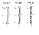
- the resonance wave XW 4 is generated by composing the traveling waves TW 4 and TW 4 " having the same phase, as illustrated in Fig. 5C , so that the resonance wave XW 4 becomes the loop LP at the middle of the open ends 11 and 12.
- the inventors made an assumption about that the stationary wave SW 1 which is not alleviated as much as the fourth-order stationary wave SW 4 is caused by the above reason.
- the variation in the sound pressure at the position of the open end 11 and the sound pressure of the open end 12 while having the same phase is in common with the eighth-order stationary wave SW 8 . Therefore, the inventors made an assumption about that the eighth-order stationary wave SW 8 is not alleviated by the same reason as the fourth-order stationary wave SW 4 .
- a second verification will be explained.
- the speaker 9A is illustrated in Fig. 2 , by inputting a test sound signal ST to the speaker unit 2 and measuring the sound wave irradiated from the speaker unit 2 at a measuring point P in the space S (more specifically, measuring point P in the inner vicinity of the position in which the wall surfaces 4D, 4B and 4R are intersected) (see Fig. 2 ), the inventors calculated a frequency response R-9A which is a spectrum difference between the input signal ST and a measured signal SM by means of simulation.
- a speaker 9A BS ' is configured by removing the open pipe OP from the speaker 9A BS .
- a position near a front surface of a center speaker unit SU CNT in the speakers 9A BS and 9A BS ' is set as a first measurement point P-1
- a position near a front surface of a bass reflex port BP in the speakers 9A BS and 9A BS ' is set as a second measurement point P-2
- an inner position of a substantial center of a wall surface opposite to the side of the speaker unit SU CNT is set to a third measurement point P-3.
- a sound signal is input to the speaker unit SU CNT of the speakers 9A BS and 9A BS ', and a sound wave irradiated from the speaker unit SU CNT is measured at the measurement points P-1, P-2 and P-3 in accordance with the sound signal.
- frequency responses R 1 -9A BS , R 2 -9A BS and R 3 -9A BS which are spectrum differences of the input signal ST of the speaker unit SU CNT and the measured signal SM at the measurement points P-1, P-2 and P-3 are calculated.
- frequency responses R 1 -9A BS ', R 2 -9A BS ' and R 3 -9A BS ' which are spectrum differences of the input signal ST of the speaker unit SU CNT and the measured signal SM at the measurement points P-1, P-2 and P-3 are calculated.
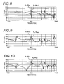
- Fig. 8 illustrates the frequency responses R 1 -9A BS and R-9A BS ' at the same frequency axis.
- FIG. 9 illustrates the frequency responses R 2 -9A BS and R 2 -9A BS ' at the same frequency axis.
- Fig. 10 illustrates the frequency responses R 3 -9A BS and R 3 -9A BS ' at the same frequency axis.
- peaks are generated in the proximity of 300 Hz in the frequency responses R 1 -9A BS ', R 2 -9A BS ' and R 3 -9A BS '. They indicate that the second-stationary wave SW 2 is not effectively suppressed by the resonance of the bass reflex port BF in the bass reflex speaker.
- the peak is split into two in the proximity of 300 Hz, and each amplitude is smaller than that of the frequency responses R 1 -9A BS ', R 2 -9A BS ' and R 3 -9A BS '. It is confirmed from this fact that the second-order stationary wave SW 2 which is an object to be suppressed can be suppressed by the speaker 9A BS .
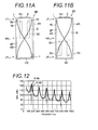
- Fig. 11A is a front view of a speaker 9B which is an audio apparatus according to a second embodiment of the present invention.
- the open pipe 10 in the space S (the hollow space S enclosed by three pairs of opposite surfaces of the wall surfaces 4U and 4D, the wall surfaces 4F and 4B, and the wall surfaces 4L and 4R) of the cabinet 1 in the speaker 9 according to the first embodiment is replaced by an open pipe 30 in the speaker 9B according to the second embodiment.
- the open pipe 30 has a pipe length of a substantially half wavelength of the first-order stationary wave SW 1 .
- the open pipe 30 is formed in a U-shape.
- the open pipe 30 is accommodated in the space S in a posture which satisfies following condition 'c1' in which both open ends 31 and 32 of the open pipe 30 are disposed at positions of the same loop LP as that the lowest order one of the stationary waves SW k to be suppressed in the space S or near the positions.
- the open ends 31 and 32 are disposed at the positions of the loops LP 1-1 , which is on the side of the wall surface 4U, of two loops LP 1-1 and LP 1-2 of the first-order stationary wave SW 1 .
- the open ends 31 and 32 may be disposed at the position of the loop LP 1-2 on the side of wall surface 4D.
- the open pipe 30 can be accommodated in the space S in the posture illustrated in Fig. 11A or 11B , thereby reducing the first-order or more stationary wave SW k in the space S.
- the inventors carried out the following verification in order to confirm the effect of this embodiment.
- the speaker 9B which is the example illustrated in Fig. 11A
- the inventors calculated a frequency response R-9B which is a spectrum difference between the input signal ST and a measured signal SM by means of simulation.
- a frequency response R-9B' which is a spectrum difference between the input signal ST and a measured signal SM by means of simulation.
- Fig. 12 illustrates the frequency responses R-9B and R-9B' at the same frequency axis.
- a peak appears in the proximity of 160 Hz, 320 Hz, 480 Hz, 650 Hz, 820 Hz, and 970 Hz in any frequency responses R-9B and R-9B'.
- amplitude of the peak in the proximity of 320 Hz, 650 Hz and 970 Hz is substantially equal to that in the frequency response R-9B', but amplitude of the peaks in the proximity of 160 Hz, 480 Hz and 820 Hz is smaller than that in the frequency response R-9B'.
- the peaks in the proximity of 160 Hz, 480 Hz and 820 Hz are split. It is confirmed from this fact that the first-order stationary wave SW 1 (160 Hz), the third-order stationary wave SW 3 (480 Hz) and the fifth-order stationary wave SW 5 (820 Hz) are suppressed in the space S by the speaker 9B.
- the invertors made an assumption about that suppression of the stationary waves SW 1 , SW 3 and SW 5 in the space S of the speaker 9B is caused by the following reason on the basis of the verified result of the verification.
- two open ends 31 and 32 of the open pipe 30 in the space S are disposed at the position of the loop LP 1-1 of the stationary wave SW 1 in the speaker 9.
- the position of the loop LP 1-1 of the stationary wave SW 1 corresponds to the loops LP 2-1 , LP 3-1 , LP 4-1 and LP 5-1 , ... of the second-order and subsequent stationary waves SW 2 , SW 3 , SW 4 and SW 5 , ....
- the medium (air) in the vicinity of the open ends 31 and 32 of the open pipe 30 is vibrated by variation in sound pressure of the loop LP 1-1 of the stationary wave SW 1 , and traveling waves TW 1 and TW 1 ' having the same phase and traveling in an opposite direction are generated.
- the reason why the traveling waves TW 1 and TW 1 ' have the same phase is that a source of generating the traveling waves TW 1 and TW 1 ' is identical. If the traveling waves TW 1 and TW 1 ' are composed in the open pipe 30, a resonance wave XW 1 having the same wavelength ⁇ 1 as that of the stationary wave SW 1 is generated.
- the resonance wave XW 1 is generated by composing the traveling wave TW 1 and TW 1 ', as illustrated in Fig. 14A , so that the resonance wave XW 1 at the middle of the open ends 31 and 32 becomes the loop LP. Since the pipe length of the open pipe 30 is equal to a length ⁇ 1 /2 corresponding to the half wavelength of the stationary wave XW 1 , the center of the open ends 31 and 32 becomes the loop LP, and thus the sides of the open ends 31 and 32 become the node ND. For this reason, distribution in sound pressure of the stationary wave SW 1 at the positions of the open ends 31 and 32 is alleviated. The inventors made an assumption about that alleviation of the stationary wave SW 1 is caused by the above reason.
- resonance waves XW 3 , XW 5 , XW 7 , ... generated when the medium (air) in the vicinity of the open ends 31 and 32 of the open pipe 30 is vibrated become the node ND at the sides of the open ends 31 and 32. Therefore, the inventors made an assumption about that the odd-order stationary waves SW 3 , SW 5 , SW 7 , ... of three-order or subsequent are alleviated by the same reason.
- the medium (air) in the vicinity of the open ends 31 and 32 is vibrated by variation in sound pressure of the loop LP 2-1 of the stationary wave SW 2 , and traveling waves TW 2 and TW 2 " traveling in an opposite direction and having the same phase is generated. If the traveling waves TW 2 and TW 2 " are composed in the open pipe 30, a resonance wave XW 2 having the same wavelength ⁇ 2 as that of the stationary wave SW 2 is generated. As illustrated in Fig. 14B , the resonance wave XW 2 becomes the loop LP at a middle of the open ends 31 and 32.
- Fig. 15 is a front view of a speaker 9D according to a third embodiment of the present invention.
- the speaker 9D includes a cabinet 1', a speaker unit 2' fixed to an outside of the cabinet 1', and an open pipe 40' accommodated in a space S' of the cabinet 1'.
- the cabinet 1' is formed in a hollow rectangular cubic shape enclosed by wall surfaces 4U' and 4D' opposite to each other in upward and downward directions, wall surfaces 4F' and 4B' opposite to each other in back and forth directions, and wall surfaces 4L' and 4R' opposite to each other in right and left directions.
- the speaker unit 2' of the speaker 9D is fixed to a substantially center (placed at the node ND 1-1 of the first-order stationary wave SW 1 which is generated in the space S').
- the open pipe 40' of the speaker 9D is formed in a straight shape having a pipe length of the half wavelength of the second-order stationary wave SW 2 which is generated in the space S'.
- the open pipe 40' is fixed on the wall surface 4F' in the space S' in a posture which inclines with respect to the opposite direction of two opposite surfaces of the wall surfaces 4U' and 4D'.
- the open end 41' of the open pipe 40' is disposed at the position of a substantial node ND 2-1 of the stationary wave SW 2
- the open end 42' is disposed at the position of a substantial loop LP 2-2 of the stationary wave SW 2 .
- the speaker 9D it is possible to suppress the stationary wave SW k which is generated in the opposite direction of the wall surfaces 4U' and 4D'.
- the open pipe 40' is formed in the straight shape in the speaker 9D, it is possible to conveniently manufacture or machine the open pipe 40', as compared to the case of the speakers 9 to 9C.
- the inventors carried out the following verification in order to confirm the effect of the third embodiment.
- the speaker 9D illustrated in Fig. 15 by inputting a test sound signal ST to the speaker unit 2' and measuring the sound wave irradiated from the speaker unit 2' at a measuring point P in the space S (more specifically, a measuring point P in the inner vicinity of the position in which the wall surfaces 4D', 4B' and 4R' are intersected)(see Fig. 15 ), the inventors calculated a frequency response R-9D which is a spectrum difference between the input signal ST and a measured signal SM by means of simulation.
- a frequency response R-9D' which is a spectrum difference between the input signal ST and a measured signal SM by means of simulation.
- Fig. 16 illustrates the frequency responses R-9D and R-9D' at the same frequency axis.
- a peak appears in the proximity of 300 Hz in any frequency responses R-9D and R-9D'.
- amplitude of the peak in the proximity of 300 Hz is smaller than that in the frequency response R-9D'.
- the peak in the proximity of 300 Hz is split. It is confirmed from this fact that the second-order stationary wave SW 2 is suppressed in the space S' by the speaker 9D'.
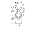
- Fig. 17 is a front view of a speaker 9E according to a fourth embodiment of the present invention.
- the speaker 9E is a modified speaker in which both open ends of the open pipe 20 are covered with an air-permeable sound absorbing material (e.g., non-woven textile fabric).
- both open ends 91, 92 of the open pipe 20 are wholly covered with the air-permeable sound absorbing material in the example of Fig. 17 , but only a portion of the open ends 91 and/or 92 may be covered with the air-permeable sound absorbing material.
- the air-permeable sound absorbing material has a property of blunting the peak or deep in the frequency response in the space which is spaced apart from the exterior. According to the fourth embodiment, it is possible to make a suppression amount of the second stationary wave SW 2 larger than the first embodiment.
- the inventors carried out the following verification in order to confirm the effect of the second embodiment.
- the inventors employed the speaker 9E BS in which both open ends of the open pipe OP in the speaker 9A BS used for the verification of the first embodiment are covered with the air-permeable sound absorbing material.
- the inventors calculated frequency responses R 1 -9E BS , R 2 -9E BS and R 3 -9E BS which are a spectrum difference between the input signal ST of the speaker unit SU CNT and a measured signal SM at the measured points P-1, P-2 and P-3.
- Fig. 18 illustrates the frequency response R 1 -9E BS and the frequency response R 1 -9A BS ' ( Fig.
- Fig. 19 illustrates the frequency response R 2 -9E BS and the frequency response R 2 -9A BS ' ( Fig. 9 ) used for the verification of the first embodiment at the same frequency axis.
- Fig. 20 illustrates the frequency response R 3 -9E BS and the frequency response R 3 -9A BS ' ( Fig. 10 ) used for the verification of the first embodiment at the same frequency axis.
- FIG. 22A An example shown in Fig. 22A is an aspect described in the first embodiment ( Fig. 1A ).
- An example shown in Fig. 22B is an aspect described in the third embodiment ( Fig. 11A ).
- Aspects of Fig. 22C and Fig. 22D are also considered as modified examples of the aspect shown in Fig. 22B .
- the open pipe since the open pipe generates another stationary wave which cannot coexist with the stationary wave generated between the wall surfaces 4U and 4D, the stationary wave generated between the wall surfaces 4U and 4D can be reduced.
- the shape and form of the open pipe are arbitrary.
- the open pipe may be led out outside the cabinet 1 as shown in Fig. 22E .
- the open pipe may be led out outside the cabinet 1 and have a spiral shape as shown in Fig. 22F .
Landscapes
- Health & Medical Sciences (AREA)
- Otolaryngology (AREA)
- Physics & Mathematics (AREA)
- Engineering & Computer Science (AREA)
- Acoustics & Sound (AREA)
- Signal Processing (AREA)
- Obtaining Desirable Characteristics In Audible-Bandwidth Transducers (AREA)
- Details Of Audible-Bandwidth Transducers (AREA)
Description
- The present invention relates to a technology for suppressing a stationary wave using resonance of a pipe.
- When a sound wave of a specific frequency is irradiated in a space which is enclosed by walls, it is known that stationary waves are generated by reciprocation of the sound wave between the wall surfaces of the space, thereby having a harmful effect on the audio property of an audio appliance. In Japanese Patents Nos.
2606447 3763682 JP-A-2008-131199 2606447 3763682 JP-A-2008-131199 3763682 - The technology of Japanese Patent No.
3763682 JP-A-2008-131199 3763682 JP-A-2008-131199 - The present invention has been made to solve the above problems, and an object of the present invention is to provide a technique for suppressing a stationary wave, which is generated in a space, by use of pipe resonance of an open pipe.
- An aspect of the present invention provides an audio apparatus, including: a housing including a space which is enclosed at least one pair of opposite surfaces; and an open pipe including a first open end and a second open end positioned in the space, wherein the open pipe has a pipe length of integral multiple of a substantially half wavelength of a stationary wave which is generated in the space, and the first open end of the open pipe is disposed at a position of a substantial loop of the stationary wave which is generated in the space.
- According to the configuration above, when the stationary wave exists in the space, another stationary wave which cannot coexist with the stationary wave is generated in the open pipe, thereby reducing the stationary wave generated in the space.
- The audio apparatus may be configured so that the second open end of the open pipe is disposed at a position of a substantial node of the stationary wave which is generated in the space.
- The audio apparatus may be configured so that the first and second open ends of the open pipe are respectively disposed at positions which are spaced apart from each other by a length of odd multiple of a substantially quarter wavelength of the stationary wave along an opposite direction of the one pair of opposite surfaces.
- The audio apparatus may be configured so that the second open end of the open pipe is disposed at a position of a substantial loop of the stationary wave which is generated in the space.
- The audio apparatus may be configured so that at least one of the first and second open ends of the open pipe is wholly or partially covered with an air-permeable sound absorbing material.
-
-
Fig. 1A is a front view of a speaker according to one example of a first embodiment of the present invention. -
Fig. 1B is a front view of a speaker according to another example of the first embodiment of the present invention. -
Fig. 2 is a front view of a speaker according to another example of the first embodiment of the present invention. -
Fig. 3 is a graph illustrating a frequency response which is a first verification result of a speaker effect. -
Figs. 4A to 4E are diagrams, each illustrating a position relationship between a stationary wave and an open end of an open pipe in the speaker. -
Figs. 5A to 5C are diagrams, each illustrating a waveform of a resonance wave in the open pipe of the speaker. -
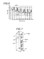
Fig. 6 is a graph illustrating a frequency response which is a verification result of a second verification of a speaker effect. -
Fig. 7 is a perspective view of a bass reflex speaker manufactured by a verification result for a third verification of a speaker effect. -
Fig. 8 is a graph illustrating a frequency response which is a verification result of the third verification of the speaker effect. -
Fig. 9 is a graph illustrating a frequency response which is a verification result of the third verification of the speaker effect. -
Fig. 10 is a graph illustrating a frequency response which is a verification result of the third verification of the speaker effect. -
Fig. 11A is a front view of a speaker according to one example of a second embodiment of the present invention. -
Fig. 11B is a front view of a speaker according to another example of the second embodiment of the present invention. -
Fig. 12 is a graph illustrating a frequency response which is a verification result of a speaker effect. -
Figs. 13A to 13E are diagrams, each illustrating a position relationship between a stationary wave and an open end of an open pipe in the speaker. -
Figs. 14A and 14B are diagrams, each illustrating a waveform of a resonance wave in the open pipe of the speaker. -
Fig. 15 is a front view of a speaker according to a third embodiment of the present invention. -
Fig. 16 is a graph illustrating a frequency response which is a verification result of the speaker. -
Fig. 17 is a front view of a speaker according to a fourth embodiment of the present invention. -
Fig. 18 is a graph illustrating a frequency response which is a verification result of the speaker. -
Fig. 19 is a graph illustrating a frequency response which is a verification result of the speaker. -
Fig. 20 is a graph illustrating a frequency response which is a verification result of the speaker. -
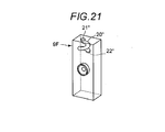
Fig. 21 is a perspective view of a speaker according to another example of the present invention. -
Figs. 22A to 22F are diagrams, each illustrating schematically and exhaustively a relationship between a stationary wave generated in a space of the cabinet and an open pipe in an audio apparatus. - Hereinafter, exemplary embodiments of the invention will be explained with reference to the accompanying drawings.
-
Fig. 1A is a front view of aspeaker 9 which is an audio apparatus according to a first embodiment of the present invention. Thespeaker 9 includes acabinet 1, aspeaker unit 2 fixed to an outside of thecabinet 1, and anopen pipe 10 accommodated in a space S of thecabinet 1. Thecabinet 1 is a member serving as a housing of thespeaker 9. Thecabinet 1 is formed in a hollow rectangular cubic shape enclosed bywall surfaces wall surfaces cabinet 1 is set to be sufficiently larger than a depth L (distance between the wall surfaces 4F and 4B; for example, L=200 mm) or a width W (distance between the wall surfaces 4L and 4R; for example, W=300 mm). - The
speaker unit 2 is an apparatus serving as a sound generating source in thespeaker 9. Thespeaker unit 2 is built in a substantially center portion of thewall surface 4U of thecabinet 1, with a sound-emission surface facing an outside. Thespeaker unit 2 is input with an electric signal from an audio apparatus (not illustrated). Thespeaker unit 2 irradiates the electric signal as a sound wave. In the case where a sound wave of the same frequency as its natural frequency is transferred to the space S from thespeaker unit 2, the sound wave reciprocates between the wall surfaces 4U and 4D of the space S, and thus plural sound waves reciprocating between the wall surfaces 4U and 4D are combined with each other to generate stationary waves SWk (k=1, 2, ...) having a wavelength λk (k=1, 2, ...) which is 2/k (k=1, 2, ...) times as much as a distance between the wall surfaces 4U and 4D. - The
open pipe 10 is a member for reducing the stationary waves SWk. Theopen pipe 10 has a pipe length of a substantially half wavelength of the lowest order one (first-order stationary wave SW1 in the example ofFig. 1A ) of the stationary waves SWk to be suppressed. The term "substantially" or its similar term in the meaning of the substantially half wavelength of the lowest order one of the stationary waves SWk to be suppressed indicates a variation within ±20% of the half wavelength, and the same applies to the following embodiments. Theopen pipe 10 is formed in a J-shape which is bent at a right angle at two points in the halfway leading from oneopen end 11 to the otheropen end 12. Theopen pipe 10 is accommodated in the space S in a posture which satisfies two following conditions 'a1' and 'b1', where condition 'a1' is one condition in which oneopen end 11 and the otheropen end 12 are respectively disposed at positions of a substantial loop LP and a substantial node ND of a sound pressure of the lowest order one of the stationary waves SWk to be suppressed in the space S; and condition 'b1' is another condition in which oneopen end 11 and the otheropen end 12 are respectively disposed at each position spaced apart by about quarter wavelength of the stationary waves SWk in an opposite direction of two opposite surfaces of the wall surfaces 4U and 4D in the space S. The term "substantial" or its similar term in the meaning of the position of the substantial loop LP indicates a variation within ±10% from the position of the loop of the wavelength of the stationary wave. Further, the term "substantial" or its similar term in the meaning of the position of the substantial node ND indicates a variation within ±10% from the position of the node of the wavelength of the stationary wave. The same applies to the following embodiments with regard to the range of the variation. - The configuration of the
speaker 9 according to the first embodiment is described in detailed hereinbefore. In the example ofFig. 1A , theopen end 11 is disposed at the position of the loop LP1-1, which is on the side of thewall surface 4U, of two loops LP1-1 and LP1-2 of the first-order stationary wave SW1, and theopen end 12 is disposed at the position of the node ND1-1 between the two loops LP1-1 and LP1-2. As illustrated in the example ofFig. 1B , however, theopen end 11 may be disposed at the position of the loop LP1-2 on the side ofwall surface 4D, and theopen end 12 may be disposed at the position of the node ND1-1. Theopen pipe 10 is accommodated in the space S in the posture illustrated inFigs. 1A and 1B , thereby reducing first-order or more stationary waves SWk in the space S. As well known, in the case where a sound generating source is positioned at the position of the node ND1-1 of the first-order stationary wave SW1 on the wall surfaces 4U, 4D, 4L, 4F and 4B forming thecabinet 1 of thespeaker 9, the odd-order first-order stationary waves SW1, SW3, SW5, ... in the space S are suppressed by vibration of the sound generating source (specifically, seeJP-A-2008-131199 speaker 9A illustrated in the example ofFig. 2 , in the case in which thespeaker unit 2 is disposed at the position of the node ND1-1 of the first-order stationary wave SW1, anopen pipe 20 having a pipe length of approximately half wavelength of the second stationary wave SW2 may be accommodated in the space S in the posture which satisfies the above-described conditions 'a1' and 'b1'. When theopen pipe 20 is accommodated in the space S in the above posture, it is also possible to reduce the first-order or more stationary wave SWk in the space S. - The inventors carried out three verifications in order to confirm the effect of this embodiment. First, a first verification will be explained. For the
speaker 9 which is the example illustrated inFig. 1A , by inputting a test sound signal ST (e.g., white noise) to thespeaker unit 2 and measuring the sound wave irradiated from thespeaker unit 2 at a measuring point P in the space S (more specifically, a measuring point P in the inner vicinity of the position in which the wall surfaces 4D, 4B and 4R are intersected) (seeFig. 1A ), the inventors calculated a frequency response R-9 which is a spectrum difference between the input signal ST and a measured signal SM by means of simulation. Similarly, for a speaker 9' in which theopen pipe 10 is removed from thespeaker 9, by inputting a test sound signal ST to thespeaker unit 2 and measuring the sound wave irradiated from thespeaker unit 2 at the measuring point P, the inventors calculated a frequency response R-9' which is a spectrum difference between the input signal ST and a measured signal SM by means of simulation.Fig. 3 illustrates the frequency responses R-9 and R-9' at the same frequency axis. - Referring to
Fig. 3 , a peak appears in the proximity of 160 Hz, 320 Hz, 480 Hz, 650 Hz, 820 Hz, and 960 Hz in any frequency responses R-9 and R-9'. For the frequency response R-9, amplitude of the peak in the proximity of 650 Hz is substantially equal to that in the frequency response R-9', but amplitude of the peaks in the proximity of 160 Hz, 320 Hz, 480 Hz, 820 Hz and 970 Hz is smaller than that in the frequency response R-9'. Also, for the frequency response R-9, the peaks in the proximity of 160 Hz, 320 Hz, 480 Hz, 820 Hz and 970 Hz are split. It is confirmed from this fact that the first-order stationary wave SW1 (160 Hz), the second-order stationary wave SW2 (320 Hz), the third-order stationary wave SW3 (480 Hz), the fifth-order stationary wave SW5 (820 Hz) and the sixth-order stationary wave SW6 (970 Hz) are suppressed in the space S by thespeaker 9. - The invertors made an assumption about that suppression of the stationary waves SW1, SW2, SW3, SW5 and SW6 by the
speaker 9 which is the example ofFig. 1A is caused by the following reason, except for the fourth-order stationary wave SW4, on the basis of the verified result of the first verification. As illustrated inFigs. 4A to 4E , theopen end 11 of theopen pipe 10 in the space S is disposed at the position of the loop LP1-1 of the stationary wave SW1 in thespeaker 9. The position of the loop LP1-1 of the stationary wave SW1 corresponds to the loops LP2-1, LP3-1, LP4-1, LP5-1, ... of the second-order and subsequent stationary waves SW2, SW3, SW4, SW5, .... Also, theopen end 12 of theopen pipe 10 in the space S is disposed at the position of the node ND1-1 of the stationary wave SW1. The position of the node ND1-1 of the stationary wave SW1 corresponds to the loops LP2-2 and LP4-3 of the second and subsequent even-order stationary waves SW2 and SW4 and the nodes ND3-2 and ND5-3 of the third-order and subsequent odd-order stationary waves SW3 and SW5. Accordingly, in the case where the stationary wave SWk (k=1, 2, ...) is generated in the space S, a medium (air) in the vicinity of theopen end 11 of theopen pipe 10 is vibrated by variation in sound pressure at the position of the loop LP of the odd- and even-order stationary wave SWk, and a medium (air) in the vicinity of theopen end 12 is vibrated by variation in sound pressure at the position of the loop LP of the even-order stationary wave SWk. - In view of the relationship between the first-order stationary wave SW1 in the space S and the behavior of the medium (air) in the
open pipe 10, the medium (air) in the vicinity of theopen end 11 of theopen pipe 10 is vibrated by variation in sound pressure of the loop LP1-1 of the stationary wave SW1, and a traveling wave TW1 facing from theopen end 11 to theopen end 12 is generated. The traveling wave TW1 is transferred into theopen pipe 10, and then reaches theopen end 12. Since the position in which theopen end 12 of theopen pip 10 is disposed in the space S is the position of the node ND1-1 of the stationary wave SW1, the medium (air) in the vicinity of theopen end 12 is hardly vibrated even though the traveling wave TW1 reaches theopen end 12. For this reason, if the traveling wave TW1 reaches theopen end 12, a reflected wave RW1 is generated in theopen end 12. If the reflected wave RW1 and the traveling wave TW1 are composed in theopen pipe 10, a resonance wave XW1 having the same wavelength λ1 as that of the stationary wave SW1 is generated. The resonance wave XW1 is generated by composing the traveling wave TW1 and the reflected wave RW1 reflected by the traveling wave TW1 from theopen end 12, as illustrated inFig. 5A , so that the resonance wave XW1 at the sides theopen end 11 and theopen end 12 becomes the node ND, respectively. For this reason, distribution in sound pressure of the stationary wave SW1 at the position of theopen end 11 is alleviated. The inventors made an assumption about that alleviation of the stationary wave SW1 is caused by the above reason. Also, the existence of the node ND at the position of theopen end 12 is in common with all odd-order stationary wave SWk. Therefore, the inventors made an assumption about that the odd-order stationary waves SW3, SW5, SW7, ... of three-order or subsequent are alleviated by the same reason. - Next, in view of the relationship between the second-order stationary wave SW2 in the space S and the behavior of the medium (air) in the
open pipe 10, the medium (air) in the vicinity of the open ends 11 and 12 of theopen pipe 10 is vibrated by variation in sound pressure of the loops LP2-1 and LP2-2 of the stationary wave SW2, and traveling waves TW2 and TW2" traveling in an opposite direction and having a n phase difference therebetween is generated. The reason why the traveling waves TW2 and TW2" have the n phase difference is that the sound pressure of two adjacent loops LP in the stationary wave SWk are varied while having the n phase difference. If the traveling waves TW2 and TW2" are composed in theopen pipe 10, a resonance wave XW2 having the same wavelength λ2 as that of the stationary wave SW2 is generated. The resonance wave XW2 is generated by composing the traveling waves TW2 and TW2" having the n phase difference, as illustrated inFig. 5B , so that the resonance wave XW2 becomes the node ND at a middle of the open ends 11 and 12. Also, since a pipe length (pipe length of a half wavelength of the first-order stationary wave SW1) of theopen pipe 10 is equal to a wavelength λ2 (λ2 = λ1/2) of the stationary wave SW2, if the middle of the open ends 11 and 12 becomes the node ND, the sides of the open ends 11 and 12 also become the node ND. For this reason, distribution in sound pressure of the stationary wave SW2 at the positions of the open ends 11 and 12 is alleviated. The inventors made an assumption about that the alleviation of the stationary wave SW2 is caused by the above reason. Also, the variation in the sound pressure at the position of theopen end 11 and the sound pressure of theopen end 12 while having the n phase difference is in common with the sixth-order stationary wave SW6 and the tenth-order stationary wave SW10. Therefore, the inventors made an assumption about that the sixth-order stationary wave SW6 or the tenth-order stationary wave SW10 is alleviated by the same reason. - Next, in view of the relationship between the fourth-order stationary wave SW4 in the space S and the behavior of the medium (air) in the
open pipe 10, the medium (air) in the vicinity of the open ends 11 and 12 of theopen pipe 10 is vibrated by variation in sound pressure of the loops LP4-1 and LP4-3 of the stationary wave SW4, and traveling waves TW4 and TW4" traveling in an opposite direction and having the same phase is generated. The reason why the traveling waves TW4 and TW4" have the same phase is that the sound pressure of two loops LP, which are spaced apart from each other while one loop LP is interposed therebetween, in the stationary wave SWk are varied at the same phase. If the traveling waves TW4 and TW4" are composed in theopen pipe 10, a resonance wave XW4 having the same wavelength λ4 as that of the stationary wave SW4 is generated. The resonance wave XW4 is generated by composing the traveling waves TW4 and TW4" having the same phase, as illustrated inFig. 5C , so that the resonance wave XW4 becomes the loop LP at the middle of the open ends 11 and 12. Also, since the pipe length (pipe length of a half wavelength of the first-order stationary wave SW1) of theopen pipe 10 is two times of a wavelength λ4 (λ4 = λ1/4) of the stationary wave SW4, if the middle of the open ends 11 and 12 becomes the loop LP, the sides of the open ends 11 and 12 also become the loop LP. For this reason, distribution in sound pressure of the stationary wave SW4 at the positions of the open ends 11 and 12 is not alleviated. The inventors made an assumption about that the stationary wave SW1 which is not alleviated as much as the fourth-order stationary wave SW4 is caused by the above reason. Also, the variation in the sound pressure at the position of theopen end 11 and the sound pressure of theopen end 12 while having the same phase is in common with the eighth-order stationary wave SW8. Therefore, the inventors made an assumption about that the eighth-order stationary wave SW8 is not alleviated by the same reason as the fourth-order stationary wave SW4. - Next, a second verification will be explained. For the
speaker 9A is illustrated inFig. 2 , by inputting a test sound signal ST to thespeaker unit 2 and measuring the sound wave irradiated from thespeaker unit 2 at a measuring point P in the space S (more specifically, measuring point P in the inner vicinity of the position in which the wall surfaces 4D, 4B and 4R are intersected) (seeFig. 2 ), the inventors calculated a frequency response R-9A which is a spectrum difference between the input signal ST and a measured signal SM by means of simulation. Similarly, for aspeaker 9A' in which theopen pipe 10 is removed from the speaker, by inputting a test sound signal ST to thespeaker unit 2 and measuring the sound wave irradiated from thespeaker unit 2 at the measuring point P, the inventors calculated a frequency response R-9A' which is a spectrum difference between the input signal ST and a measured signal SM by means of simulation.Fig. 6 illustrates the frequency responses R-9A and R-9A' at the same frequency axis. - Referring to
Fig. 6 , a peak appears in the proximity of 160 Hz, 320 Hz, 480 Hz, 650 Hz, 820 Hz, and 970 Hz in any frequency responses R-9A and R-9A'. For the frequency response R-9A, amplitude of the peak in the proximity of 160 Hz, 320 Hz, 480 Hz, 650 Hz, 820 Hz, and 970 Hz is smaller than that in the frequency response R-9A'. The peaks in the proximity of 320 Hz, 480 Hz, 650 Hz, 820 Hz and 970 Hz are split. It is confirmed from this fact that the first-order to six-order stationary waves SW1 to SW6 are suppressed in the space S by thespeaker 9A. - Next, a third verification will be explained. In the third verification, the inventors actually measured the frequency response from the open pipe which is accommodated in a bass reflex speaker and has a pipe length of a substantially half wavelength of the second-order stationary wave SW2. More specifically, as illustrated in
Fig. 7 , aspeaker 9ABS is configured in which an open pipe OP having a pipe length of a substantially half wavelength of the second-order stationary wave SW2 is accommodated in the space S (space S having dimensions of a vertical width H (H=1050mm), a horizontal width W (W=200mm), and a depth L (L=300mm)) in the bass reflex speaker in the posture satisfying the above conditions 'a1' and 'b1'. In addition, aspeaker 9ABS' is configured by removing the open pipe OP from thespeaker 9ABS. - In addition, a position near a front surface of a center speaker unit SUCNT in the
speakers speakers speakers - For the
speaker 9ABS, frequency responses R1-9ABS, R2-9ABS and R3-9ABS which are spectrum differences of the input signal ST of the speaker unit SUCNT and the measured signal SM at the measurement points P-1, P-2 and P-3 are calculated. Similar to thespeaker 9ABS', frequency responses R1-9ABS', R2-9ABS' and R3-9ABS' which are spectrum differences of the input signal ST of the speaker unit SUCNT and the measured signal SM at the measurement points P-1, P-2 and P-3 are calculated.Fig. 8 illustrates the frequency responses R1-9ABS and R-9ABS' at the same frequency axis.Fig. 9 illustrates the frequency responses R2-9ABS and R2-9ABS' at the same frequency axis.Fig. 10 illustrates the frequency responses R3-9ABS and R3-9ABS' at the same frequency axis. - In
Figs. 8, 9 and 10 , peaks are generated in the proximity of 300 Hz in the frequency responses R1-9ABS', R2-9ABS' and R3-9ABS'. They indicate that the second-stationary wave SW2 is not effectively suppressed by the resonance of the bass reflex port BF in the bass reflex speaker. By contrast, for the frequency responses R1-9ABS, R2-9ABs and R3-9ABS, the peak is split into two in the proximity of 300 Hz, and each amplitude is smaller than that of the frequency responses R1-9ABS', R2-9ABS' and R3-9ABS'. It is confirmed from this fact that the second-order stationary wave SW2 which is an object to be suppressed can be suppressed by thespeaker 9ABS. - From the verification result (
Fig. 6 ) of the above-described second verification, it is verified that the first-order to sixth-order stationary waves SW1 to SW6 can be suppressed, but from the verification result (Figs. 8, 9 and 10 ) of the third verification, it is not verified that the high-order stationary waves such as the third-order to sixth-order stationary waves SW3 to SW6 can be suppressed. The inventors made an assumption about the reason as follows. If the space in thespeaker 9ABS is completely closed, the wavelengths λ2, λ3, λ4, ... of the second-order and subsequent stationary waves SW2, SW3, SW4, ... coincide with an integral multiplication of the wavelength λ1 of the first-order stationary wave SW1. However, in the case where there are additional elements such as the bass reflex port BF of thespeaker 9ABS, λ2, λ3, λ4, ... of the second-order and subsequent stationary waves SW2, SW3, SW4 may not coincide with the integral multiplication of the first-order stationary wave SW1. By contrast, the wavelength of the second-order and subsequent resonance waves XW2, XW3, XW4, ... in the open pipe OP of thespeaker 9ABS always coincide with an integral multiplication of the first resonance wave XW1. For this reason, in thespeaker 9ABS, there is a case where a frequency does not coincide with each other between the high-order stationary wave SW and the resonance wave XW. The inventors made an assumption about that the third-order to sixth-order stationary waves SW3 to SW6 are not suppressed in thespeaker 9ABS. -
Fig. 11A is a front view of aspeaker 9B which is an audio apparatus according to a second embodiment of the present invention. Theopen pipe 10 in the space S (the hollow space S enclosed by three pairs of opposite surfaces of the wall surfaces 4U and 4D, the wall surfaces 4F and 4B, and the wall surfaces 4L and 4R) of thecabinet 1 in thespeaker 9 according to the first embodiment is replaced by anopen pipe 30 in thespeaker 9B according to the second embodiment. Theopen pipe 30 has a pipe length of a substantially half wavelength of the first-order stationary wave SW1. Theopen pipe 30 is formed in a U-shape. Theopen pipe 30 is accommodated in the space S in a posture which satisfies following condition 'c1' in which both open ends 31 and 32 of theopen pipe 30 are disposed at positions of the same loop LP as that the lowest order one of the stationary waves SWk to be suppressed in the space S or near the positions. - The configuration of the
speaker 9B according to the second embodiment is described in detailed hereinbefore. In the example ofFig. 11A , the open ends 31 and 32 are disposed at the positions of the loops LP1-1, which is on the side of thewall surface 4U, of two loops LP1-1 and LP1-2 of the first-order stationary wave SW1. As illustrated in the example ofFig. 11B , however, the open ends 31 and 32 may be disposed at the position of the loop LP1-2 on the side ofwall surface 4D. Theopen pipe 30 can be accommodated in the space S in the posture illustrated inFig. 11A or 11B , thereby reducing the first-order or more stationary wave SWk in the space S. - The inventors carried out the following verification in order to confirm the effect of this embodiment. For the
speaker 9B which is the example illustrated inFig. 11A , by inputting a test sound signal ST to thespeaker unit 2 and measuring the sound wave irradiated from thespeaker unit 2 at a measuring point P in the space S (more specifically, a measuring point P in the inner vicinity of the position in which the wall surfaces 4D, 4B and 4R are intersected) (seeFig. 11A ), the inventors calculated a frequency response R-9B which is a spectrum difference between the input signal ST and a measured signal SM by means of simulation. Similarly, for aspeaker 9B' in which theopen pipe 30 is removed from thespeaker 9B, by inputting a test sound signal ST to thespeaker unit 2 and measuring the sound wave irradiated from thespeaker unit 2 at the measuring point P, the inventors calculated a frequency response R-9B' which is a spectrum difference between the input signal ST and a measured signal SM by means of simulation.Fig. 12 illustrates the frequency responses R-9B and R-9B' at the same frequency axis. - Referring to
Fig. 12 , a peak appears in the proximity of 160 Hz, 320 Hz, 480 Hz, 650 Hz, 820 Hz, and 970 Hz in any frequency responses R-9B and R-9B'. For the frequency response R-9B, amplitude of the peak in the proximity of 320 Hz, 650 Hz and 970 Hz is substantially equal to that in the frequency response R-9B', but amplitude of the peaks in the proximity of 160 Hz, 480 Hz and 820 Hz is smaller than that in the frequency response R-9B'. Also, for the frequency response R-9B, the peaks in the proximity of 160 Hz, 480 Hz and 820 Hz are split. It is confirmed from this fact that the first-order stationary wave SW1 (160 Hz), the third-order stationary wave SW3 (480 Hz) and the fifth-order stationary wave SW5 (820 Hz) are suppressed in the space S by thespeaker 9B. - The invertors made an assumption about that suppression of the stationary waves SW1, SW3 and SW5 in the space S of the
speaker 9B is caused by the following reason on the basis of the verified result of the verification. As illustrated inFigs. 13A to 13E , twoopen ends open pipe 30 in the space S are disposed at the position of the loop LP1-1 of the stationary wave SW1 in thespeaker 9. The position of the loop LP1-1 of the stationary wave SW1 corresponds to the loops LP2-1, LP3-1, LP4-1 and LP5-1, ... of the second-order and subsequent stationary waves SW2, SW3, SW4 and SW5, .... Accordingly, in the case where the stationary wave SWk (k=1, 2, ...) is generated in the space S, a medium (air) in the vicinity of the open ends 31 and 32 of theopen pipe 30 is vibrated by variation in sound pressure at the position of the loop LP of each stationary wave SWk. - In view of the relationship between the first-order stationary wave SW1 in the space S and the behavior of the medium (air) in the
open pipe 30, the medium (air) in the vicinity of the open ends 31 and 32 of theopen pipe 30 is vibrated by variation in sound pressure of the loop LP1-1 of the stationary wave SW1, and traveling waves TW1 and TW1' having the same phase and traveling in an opposite direction are generated. The reason why the traveling waves TW1 and TW1' have the same phase is that a source of generating the traveling waves TW1 and TW1' is identical. If the traveling waves TW1 and TW1' are composed in theopen pipe 30, a resonance wave XW1 having the same wavelength λ1 as that of the stationary wave SW1 is generated. The resonance wave XW1 is generated by composing the traveling wave TW1 and TW1', as illustrated inFig. 14A , so that the resonance wave XW1 at the middle of the open ends 31 and 32 becomes the loop LP. Since the pipe length of theopen pipe 30 is equal to a length λ1/2 corresponding to the half wavelength of the stationary wave XW1, the center of the open ends 31 and 32 becomes the loop LP, and thus the sides of the open ends 31 and 32 become the node ND. For this reason, distribution in sound pressure of the stationary wave SW1 at the positions of the open ends 31 and 32 is alleviated. The inventors made an assumption about that alleviation of the stationary wave SW1 is caused by the above reason. Also, resonance waves XW3, XW5, XW7, ... generated when the medium (air) in the vicinity of the open ends 31 and 32 of theopen pipe 30 is vibrated become the node ND at the sides of the open ends 31 and 32. Therefore, the inventors made an assumption about that the odd-order stationary waves SW3, SW5, SW7, ... of three-order or subsequent are alleviated by the same reason. - Next, in view of the relationship between the second-order stationary wave SW2 in the space S and the behavior of the medium (air) in the
open pipe 30, the medium (air) in the vicinity of the open ends 31 and 32 is vibrated by variation in sound pressure of the loop LP2-1 of the stationary wave SW2, and traveling waves TW2 and TW2" traveling in an opposite direction and having the same phase is generated. If the traveling waves TW2 and TW2" are composed in theopen pipe 30, a resonance wave XW2 having the same wavelength λ2 as that of the stationary wave SW2 is generated. As illustrated inFig. 14B , the resonance wave XW2 becomes the loop LP at a middle of the open ends 31 and 32. Since a pipe length of theopen pipe 30 is equal to the wavelength λ2 of the stationary wave SW2, if the middle of the open ends 31 and 32 becomes the loop LP, the sides of the open ends 11 and 12 also become the loop LP. For this reason, distribution in sound pressure of the stationary wave SW2 at the positions of the open ends 31 and 32 is not alleviated. The inventors made an assumption about that the stationary wave SW2 is not alleviated by the above reason. Also, the resonance waves XW4, XW6, XW8, ... generated when the medium (air) in the vicinity of the open ends 31 and 32 of theopen pipe 30 is vibrated become the loop LP at the sides of the open ends 31 and 32. Therefore, the inventors made an assumption about that the even-order stationary waves SW4, SW6, SW8, ... of fourth-order or subsequent are not alleviated by the same reason. -
Fig. 15 is a front view of aspeaker 9D according to a third embodiment of the present invention. Thespeaker 9D includes a cabinet 1', a speaker unit 2' fixed to an outside of the cabinet 1', and an open pipe 40' accommodated in a space S' of the cabinet 1'. The cabinet 1' is formed in a hollow rectangular cubic shape enclosed bywall surfaces 4U' and 4D' opposite to each other in upward and downward directions, wall surfaces 4F' and 4B' opposite to each other in back and forth directions, andwall surfaces 4L' and 4R' opposite to each other in right and left directions. A width W' (distance between the wall surfaces 4L' and 4R'; for example, W'=430 mm) is set to be larger than a depth L' (distance between the wall surfaces 4F' and 4B'; for example, L'=200 mm). In addition, a height H (distance between the wall surfaces 4U' and 4D'; for example, H'=1050 mm) in the space S is set to be larger than the width W'. - The speaker unit 2' of the
speaker 9D is fixed to a substantially center (placed at the node ND1-1 of the first-order stationary wave SW1 which is generated in the space S'). The open pipe 40' of thespeaker 9D is formed in a straight shape having a pipe length of the half wavelength of the second-order stationary wave SW2 which is generated in the space S'. The open pipe 40' is fixed on thewall surface 4F' in the space S' in a posture which inclines with respect to the opposite direction of two opposite surfaces of the wall surfaces 4U' and 4D'. The open end 41' of the open pipe 40' is disposed at the position of a substantial node ND2-1 of the stationary wave SW2, and the open end 42' is disposed at the position of a substantial loop LP2-2 of the stationary wave SW2. With thespeaker 9D, it is possible to suppress the stationary wave SWk which is generated in the opposite direction of the wall surfaces 4U' and 4D'. Also, since the open pipe 40' is formed in the straight shape in thespeaker 9D, it is possible to conveniently manufacture or machine the open pipe 40', as compared to the case of thespeakers 9 to 9C. - The inventors carried out the following verification in order to confirm the effect of the third embodiment. For the
speaker 9D illustrated inFig. 15 , by inputting a test sound signal ST to the speaker unit 2' and measuring the sound wave irradiated from the speaker unit 2' at a measuring point P in the space S (more specifically, a measuring point P in the inner vicinity of the position in which the wall surfaces 4D', 4B' and 4R' are intersected)(seeFig. 15 ), the inventors calculated a frequency response R-9D which is a spectrum difference between the input signal ST and a measured signal SM by means of simulation. Similarly, for aspeaker 9D' in which the open pipe 40' is removed from thespeaker 9D, by inputting a test sound signal ST to thespeaker unit 2 and measuring the sound wave irradiated from the speaker unit 2' at the measuring point P, the inventors calculated a frequency response R-9D' which is a spectrum difference between the input signal ST and a measured signal SM by means of simulation.Fig. 16 illustrates the frequency responses R-9D and R-9D' at the same frequency axis. - Referring to
Fig. 16 , a peak appears in the proximity of 300 Hz in any frequency responses R-9D and R-9D'. For the frequency response R-9D, amplitude of the peak in the proximity of 300 Hz is smaller than that in the frequency response R-9D'. Also, for the frequency response R-9D, the peak in the proximity of 300 Hz is split. It is confirmed from this fact that the second-order stationary wave SW2 is suppressed in the space S' by thespeaker 9D'. -
Fig. 17 is a front view of aspeaker 9E according to a fourth embodiment of the present invention. Thespeaker 9E is a modified speaker in which both open ends of theopen pipe 20 are covered with an air-permeable sound absorbing material (e.g., non-woven textile fabric). Also, both open ends 91, 92 of theopen pipe 20 are wholly covered with the air-permeable sound absorbing material in the example ofFig. 17 , but only a portion of the open ends 91 and/or 92 may be covered with the air-permeable sound absorbing material. As known in the art, the air-permeable sound absorbing material has a property of blunting the peak or deep in the frequency response in the space which is spaced apart from the exterior. According to the fourth embodiment, it is possible to make a suppression amount of the second stationary wave SW2 larger than the first embodiment. - The inventors carried out the following verification in order to confirm the effect of the second embodiment. The inventors employed the
speaker 9EBS in which both open ends of the open pipe OP in thespeaker 9ABS used for the verification of the first embodiment are covered with the air-permeable sound absorbing material. Also, for thespeaker 9EBS, the inventors calculated frequency responses R1-9EBS, R2-9EBS and R3-9EBS which are a spectrum difference between the input signal ST of the speaker unit SUCNT and a measured signal SM at the measured points P-1, P-2 and P-3.Fig. 18 illustrates the frequency response R1-9EBS and the frequency response R1-9ABS' (Fig. 8 ) used for the verification of the first embodiment at the same frequency axis.Fig. 19 illustrates the frequency response R2-9EBS and the frequency response R2-9ABS' (Fig. 9 ) used for the verification of the first embodiment at the same frequency axis.Fig. 20 illustrates the frequency response R3-9EBS and the frequency response R3-9ABS' (Fig. 10 ) used for the verification of the first embodiment at the same frequency axis. - Referring to
Figs. 18, 19 and 20 , for the frequency responses R1-9EBS', R2-9EBS' and R3-9EBS', a steep peak is generated in the proximity of 300 Hz, but for the frequency responses R1-9EBS, R2-9EBS and R3-9EBS, amplitude in the proximity of 300 Hz is substantially flat. For thespeaker 9EBS, it is confirmed from this fact that a suppression amount of the second-order stationary wave SW2 is increased as compared to thebass reflex speaker 9ABS illustrated inFig. 7 . - Although the embodiments of the present invention have been explained hereinbefore, various embodiments can be devised in the present invention as follows.
- (1) The
open pipes speakers speaker 9F illustrated inFig. 21 , theopen pipe 20 of thespeaker 9A which is the example ofFig. 2 may be replaced by anopen pipe 20" formed in a spiral shape. In this instance, it is desirable (but non limited) that anopen end 21" of theopen pipe 20" is disposed at the position of the substantial loop LP of the stationary wave SW2 in the space S, and anopen end 22" is disposed at the position of the substantial node ND of the stationary wave SW2. With the configuration, the same effect as that of the first embodiment can be achieved. Also, theopen pipe 10 or theopen pipe 20 may be formed in a zigzag shape (e.g., W-shape, N-shape, Z-shape, or S-shape). Also, in thespeakers 9B 9C and 9E, a portion of the bent portion of the respective open ends 10, 20, 30 and 40 in thecabinet 1 may be formed to protrude outward from thecabinet 1, and the portion of theopen portions cabinet 1 may be utilized as a handle for holding thespeakers - (2) The first to fourth embodiments apply the present invention to suppress the stationary wave SWk of the space in the cabinets of the
speakers - (3) In the third embodiment, the open pipe 40' is fixed on the
wall surface 4F' in the space S' in a posture which inclines with respect to the opposite direction of two opposite surfaces of the wall surfaces 4U' and 4D'. However, the open pipe 40' may be fixed on thewall surface 4B' in the space S' in a posture which inclines with respect to the opposite direction of two opposite surfaces of the wall surfaces 4U' and 4D'. Also, the open pipe 40' may be accommodated in the space S' in a posture which inclines with respect to the opposite direction of two opposite surfaces of the wall surfaces 4U' and 4D', and is not necessarily fixed to thewall surface 4F' or thewall surface 4B'. For example, the open end 41' of the open pipe 40' may be disposed near the intersected position of the wall surfaces 4F' and 4L', and the open end 42' may be disposed near the intersected position of the wall surfaces 4B' and 4R'. By contrast, the open end 42' of the open pipe 40' may be disposed near the intersected position of the wall surfaces 4F' and 4L', and the open end 41' may be disposed near the intersected position of the wall surfaces 4B' and 4R'. - (4) In the third embodiment, the open pipe 40' is formed in the straight shape. However, the open pipe 40' may be bent in a J-shape, a U-shape or other shapes.
- (5) In the fourth embodiment, both open ends of the
open pipe 20 in thespeaker 9A are covered with the air-permeable sound absorbing material. However, one open end of theopen pipe 20 may be covered with the air-permeable sound absorbing material. Also, one or both open ends of theopen pipe 10 of thespeaker 9 illustrated inFigs. 1A and 1B may be covered with the air-permeable sound absorbing material. Furthermore, one or both open ends of theopen pipe 30 of thespeaker 9B illustrated inFigs. 11A and 11B may be covered with the air-permeable sound absorbing material. In addition, one or both open ends of the open pipe 40' of thespeaker 9D illustrated inFig. 15 may be covered with the air-permeable sound absorbing material. - (6) In the fourth embodiment, both open ends 91, 92 of the
open pipe 20 are covered with the non-woven textile fabric which is one of the air-permeable sound absorbing material. However, a porous material of interconnected cells, such as urethane foam or foamed resin, or a member having a construction regarded as a porous material, such as glass wool, aluminum foaming metal, metallic fiberboard, wood chip or its debris, wood fiber, pulp fiber, MPP (microperforated panel), cow fur felt, recovered wool felt, wool, cotton, non-woven fabric, cloth, synthetic fiber, wood powder molding material, or paper molding material may be used as the non-woven textile fabric. - (7) In the first embodiment to the fourth embodiment, the
open pipes open pipes open pipes 20 and 40' may be a substantially half wavelength of the third-order or subsequent stationary wave SWk. Further, although theopen pipes - (8) In the first, second and fourth embodiments, plural kinds of
open pipes cabinet 1. Also, in the third embodiment, plural kinds of open pipes 40' having different pipe length may be accommodated in the space S' in the cabinet 1'. In addition, in the third embodiment, in order to suppress plural kinds of stationary waves SWk among the stationary waves SWk which are generated in the opposite direction of thewall surface 4U' and 4D', the opposite direction of thewall surface 4F' and 4B', and the opposite direction of thewall surface 4L' and 4R', plural kinds of open pipes 40' having different slope direction may be accommodated in the space S' in the cabinet 1'. - (9) In the first, second and fourth embodiments, the stationary wave SWk in the direction of the wall surfaces 4U and 4D in the space S in the
cabinet 1 is a target to be suppressed. However, the stationary wave SWk in the direction of the wall surfaces 4F and 4B or the stationary wave SWk in the direction of the wall surfaces 4L and 4R may be a target to be suppressed, and the open pipes for suppressing the stationary waves may be replaced by theopen pipes open pipes - (10) The present invention focuses on reducing a stationary wave which is generated in a space enclosed by at least a pair of opposed surfaces of a housing and providing in the housing an open pipe that generates another stationary wave which cannot coexist with the stationary wave.
Figs. 22A to 22F are diagrams, each illustrating schematically and exhaustively a relationship between a stationary wave generated in a space of the cabinet and an open pipe in the audio apparatus. Those diagrams show an open pipe L2 provided in a housing of the audio apparatus, a first open end N1 and a second open end N2 of the open pipe L2, and a length L1 extended between the first open end N1 and the second open end N2 in an opposite direction of the pair of opposed surfaces of the housing. - An example shown in
Fig. 22A is an aspect described in the first embodiment (Fig. 1A ). An example shown inFig. 22B is an aspect described in the third embodiment (Fig. 11A ). Aspects ofFig. 22C and Fig. 22D are also considered as modified examples of the aspect shown inFig. 22B . In those aspects, since the open pipe generates another stationary wave which cannot coexist with the stationary wave generated between the wall surfaces 4U and 4D, the stationary wave generated between the wall surfaces 4U and 4D can be reduced. - In these cases, the shape and form of the open pipe are arbitrary. The open pipe may be led out outside the
cabinet 1 as shown inFig. 22E . In addition, the open pipe may be led out outside thecabinet 1 and have a spiral shape as shown inFig. 22F .
Claims (5)
- An audio apparatus, comprising:a housing including a space which is enclosed at least one pair of opposite surfaces; andan open pipe including a first open end and a second open end positioned in the space, whereinthe open pipe has a pipe length of integral multiple of a substantially half wavelength of a stationary wave which is generated in the space, andthe first open end of the open pipe is disposed at a position of a substantial loop of the stationary wave which is generated in the space.
- The audio apparatus according to claim 1, wherein
the second open end of the open pipe is disposed at a position of a substantial node of the stationary wave which is generated in the space. - The audio apparatus according to claim 1 or 2, wherein
the first and second open ends of the open pipe are respectively disposed at positions which are spaced apart from each other by a length of odd multiple of a substantially quarter wavelength of the stationary wave along an opposite direction of the one pair of opposite surfaces. - The audio apparatus according to claim 1, wherein
the second open end of the open pipe is disposed at a position of a substantial loop of the stationary wave which is generated in the space. - The audio apparatus according to any one of claims 1 to 4, wherein
at least one of the first and second open ends of the open pipe is wholly or partially covered with an air-permeable sound absorbing material.
Applications Claiming Priority (2)
| Application Number | Priority Date | Filing Date | Title |
|---|---|---|---|
| JP2011196855 | 2011-09-09 | ||
| JP2012176086A JP6044164B2 (en) | 2011-09-09 | 2012-08-08 | Sound equipment |
Publications (3)
| Publication Number | Publication Date |
|---|---|
| EP2568718A2 true EP2568718A2 (en) | 2013-03-13 |
| EP2568718A3 EP2568718A3 (en) | 2017-04-05 |
| EP2568718B1 EP2568718B1 (en) | 2020-04-01 |
Family
ID=47172195
Family Applications (1)
| Application Number | Title | Priority Date | Filing Date |
|---|---|---|---|
| EP12006272.4A Active EP2568718B1 (en) | 2011-09-09 | 2012-09-05 | Audio apparatus |
Country Status (4)
| Country | Link |
|---|---|
| US (1) | US8678130B2 (en) |
| EP (1) | EP2568718B1 (en) |
| JP (1) | JP6044164B2 (en) |
| CN (1) | CN103002377B (en) |
Cited By (1)
| Publication number | Priority date | Publication date | Assignee | Title |
|---|---|---|---|---|
| EP2775734B1 (en) * | 2013-03-07 | 2020-01-22 | Yamaha Corporation | Acoustic apparatus |
Families Citing this family (5)
| Publication number | Priority date | Publication date | Assignee | Title |
|---|---|---|---|---|
| GB2515277B (en) * | 2013-06-12 | 2019-04-17 | Airbus Operations Ltd | Distributing gas within an aircraft |
| JP6243513B2 (en) * | 2014-03-28 | 2017-12-06 | パイオニア株式会社 | Speaker system |
| CN110785806B (en) * | 2017-06-21 | 2023-09-26 | 富士胶片株式会社 | sound insulation system |
| KR102501146B1 (en) * | 2020-09-21 | 2023-02-17 | 한국과학기술원 | Sound absorbing apparatus |
| CN116491128A (en) | 2020-11-13 | 2023-07-25 | 松下电器(美国)知识产权公司 | audio device |
Citations (3)
| Publication number | Priority date | Publication date | Assignee | Title |
|---|---|---|---|---|
| JP2606447B2 (en) | 1990-05-25 | 1997-05-07 | 三菱電機株式会社 | Speaker device |
| JP3763682B2 (en) | 1998-10-14 | 2006-04-05 | パイオニア株式会社 | Speaker device |
| JP2008131199A (en) | 2006-11-17 | 2008-06-05 | Pioneer Electronic Corp | Speaker system |
Family Cites Families (13)
| Publication number | Priority date | Publication date | Assignee | Title |
|---|---|---|---|---|
| US4616731A (en) * | 1984-03-02 | 1986-10-14 | Robinson James R | Speaker system |
| JP2945983B2 (en) * | 1987-03-25 | 1999-09-06 | 久次 中村 | Speaker device |
| US5714721A (en) * | 1990-12-03 | 1998-02-03 | Bose Corporation | Porting |
| US5150417A (en) * | 1991-02-25 | 1992-09-22 | Socon Ab | Bass reflex type speaker system |
| US5373564A (en) * | 1992-10-02 | 1994-12-13 | Spear; Robert J. | Transmission line for planar waves |
| NZ510972A (en) * | 1998-11-06 | 2002-07-26 | New Transducers Ltd | Loudspeakers comprising coupling of phase uncorrelated diffuse sound source to a waveguide |
| JP3966222B2 (en) * | 2003-05-09 | 2007-08-29 | 株式会社村田製作所 | Speaker housing and speaker device |
| GB0328639D0 (en) * | 2003-12-10 | 2004-01-14 | Mitel Networks Corp | Loudspeaker enclosure incorporating a leak to compensate for the effect of acoustic modes on loudspeaker frequency response |
| US20050189164A1 (en) * | 2004-02-26 | 2005-09-01 | Chang Chi L. | Speaker enclosure having outer flared tube |
| JP2010288220A (en) * | 2009-06-15 | 2010-12-24 | Nittobo Acoustic Engineering Co Ltd | Speaker cabinet and speaker device |
| JP2011059208A (en) * | 2009-09-07 | 2011-03-24 | Yamaha Corp | Acoustic resonance device, loudspeaker enclosure, musical instrument and vehicle |
| US8401216B2 (en) * | 2009-10-27 | 2013-03-19 | Saab Sensis Corporation | Acoustic traveling wave tube system and method for forming and propagating acoustic waves |
| CN102098598A (en) * | 2011-03-15 | 2011-06-15 | 杨东佐 | a sound |
-
2012
- 2012-08-08 JP JP2012176086A patent/JP6044164B2/en active Active
- 2012-09-05 EP EP12006272.4A patent/EP2568718B1/en active Active
- 2012-09-07 US US13/606,669 patent/US8678130B2/en active Active
- 2012-09-10 CN CN201210332799.5A patent/CN103002377B/en active Active
Patent Citations (3)
| Publication number | Priority date | Publication date | Assignee | Title |
|---|---|---|---|---|
| JP2606447B2 (en) | 1990-05-25 | 1997-05-07 | 三菱電機株式会社 | Speaker device |
| JP3763682B2 (en) | 1998-10-14 | 2006-04-05 | パイオニア株式会社 | Speaker device |
| JP2008131199A (en) | 2006-11-17 | 2008-06-05 | Pioneer Electronic Corp | Speaker system |
Cited By (1)
| Publication number | Priority date | Publication date | Assignee | Title |
|---|---|---|---|---|
| EP2775734B1 (en) * | 2013-03-07 | 2020-01-22 | Yamaha Corporation | Acoustic apparatus |
Also Published As
| Publication number | Publication date |
|---|---|
| JP2013070362A (en) | 2013-04-18 |
| US8678130B2 (en) | 2014-03-25 |
| JP6044164B2 (en) | 2016-12-14 |
| CN103002377A (en) | 2013-03-27 |
| US20130062139A1 (en) | 2013-03-14 |
| EP2568718B1 (en) | 2020-04-01 |
| EP2568718A3 (en) | 2017-04-05 |
| CN103002377B (en) | 2015-10-21 |
Similar Documents
| Publication | Publication Date | Title |
|---|---|---|
| EP2568718B1 (en) | Audio apparatus | |
| KR101819733B1 (en) | Speaker module | |
| JP3763682B2 (en) | Speaker device | |
| CN104700827B (en) | Wideband sound absorbent perforated structure | |
| US20110127107A1 (en) | Acoustic resonator and sound chamber | |
| JP5817762B2 (en) | Sound equipment | |
| JP6762129B2 (en) | Sound absorber | |
| US20140291065A1 (en) | Loudspeaker having external extension | |
| JP6465096B2 (en) | Sound equipment | |
| JP2016009020A (en) | Sound absorptive panel | |
| JP2020043443A (en) | Speaker cabinet and plate material | |
| JP7459325B2 (en) | speaker system | |
| JP7342615B2 (en) | Vehicle sound deadening structure | |
| JP6782911B2 (en) | Noise reduction structure | |
| JP6243513B2 (en) | Speaker system | |
| KR101190387B1 (en) | Sound absorbing structure | |
| JP2014175806A (en) | Acoustic device | |
| CN106257933B (en) | Acoustic construction and acoustic board | |
| JP5511938B2 (en) | Sound absorbing structure | |
| JP2015060026A (en) | Acoustic structure | |
| JP7529650B2 (en) | Sound absorbing structure | |
| JP5629184B2 (en) | Back load horn type speaker | |
| GB2501266A (en) | Length of reflex duct for a loudspeaker determined by resonant modes within the loudspeaker | |
| JP7020047B2 (en) | Speaker cabinets and speaker systems | |
| JP6662712B2 (en) | Sound absorbing panel |
Legal Events
| Date | Code | Title | Description |
|---|---|---|---|
| PUAI | Public reference made under article 153(3) epc to a published international application that has entered the european phase |
Free format text: ORIGINAL CODE: 0009012 |
|
| AK | Designated contracting states |
Kind code of ref document: A2 Designated state(s): AL AT BE BG CH CY CZ DE DK EE ES FI FR GB GR HR HU IE IS IT LI LT LU LV MC MK MT NL NO PL PT RO RS SE SI SK SM TR |
|
| AX | Request for extension of the european patent |
Extension state: BA ME |
|
| PUAL | Search report despatched |
Free format text: ORIGINAL CODE: 0009013 |
|
| AK | Designated contracting states |
Kind code of ref document: A3 Designated state(s): AL AT BE BG CH CY CZ DE DK EE ES FI FR GB GR HR HU IE IS IT LI LT LU LV MC MK MT NL NO PL PT RO RS SE SI SK SM TR |
|
| AX | Request for extension of the european patent |
Extension state: BA ME |
|
| RIC1 | Information provided on ipc code assigned before grant |
Ipc: H04R 1/28 20060101AFI20170301BHEP |
|
| STAA | Information on the status of an ep patent application or granted ep patent |
Free format text: STATUS: REQUEST FOR EXAMINATION WAS MADE |
|
| 17P | Request for examination filed |
Effective date: 20171005 |
|
| RBV | Designated contracting states (corrected) |
Designated state(s): AL AT BE BG CH CY CZ DE DK EE ES FI FR GB GR HR HU IE IS IT LI LT LU LV MC MK MT NL NO PL PT RO RS SE SI SK SM TR |
|
| STAA | Information on the status of an ep patent application or granted ep patent |
Free format text: STATUS: EXAMINATION IS IN PROGRESS |
|
| 17Q | First examination report despatched |
Effective date: 20171214 |
|
| GRAP | Despatch of communication of intention to grant a patent |
Free format text: ORIGINAL CODE: EPIDOSNIGR1 |
|
| STAA | Information on the status of an ep patent application or granted ep patent |
Free format text: STATUS: GRANT OF PATENT IS INTENDED |
|
| GRAJ | Information related to disapproval of communication of intention to grant by the applicant or resumption of examination proceedings by the epo deleted |
Free format text: ORIGINAL CODE: EPIDOSDIGR1 |
|
| GRAJ | Information related to disapproval of communication of intention to grant by the applicant or resumption of examination proceedings by the epo deleted |
Free format text: ORIGINAL CODE: EPIDOSDIGR1 |
|
| GRAP | Despatch of communication of intention to grant a patent |
Free format text: ORIGINAL CODE: EPIDOSNIGR1 |
|
| STAA | Information on the status of an ep patent application or granted ep patent |
Free format text: STATUS: EXAMINATION IS IN PROGRESS |
|
| INTG | Intention to grant announced |
Effective date: 20190912 |
|
| INTG | Intention to grant announced |
Effective date: 20190912 |
|
| INTG | Intention to grant announced |
Effective date: 20190926 |
|
| GRAP | Despatch of communication of intention to grant a patent |
Free format text: ORIGINAL CODE: EPIDOSNIGR1 |
|
| STAA | Information on the status of an ep patent application or granted ep patent |
Free format text: STATUS: GRANT OF PATENT IS INTENDED |
|
| INTC | Intention to grant announced (deleted) | ||
| INTG | Intention to grant announced |
Effective date: 20191029 |
|
| GRAS | Grant fee paid |
Free format text: ORIGINAL CODE: EPIDOSNIGR3 |
|
| GRAA | (expected) grant |
Free format text: ORIGINAL CODE: 0009210 |
|
| STAA | Information on the status of an ep patent application or granted ep patent |
Free format text: STATUS: THE PATENT HAS BEEN GRANTED |
|
| AK | Designated contracting states |
Kind code of ref document: B1 Designated state(s): AL AT BE BG CH CY CZ DE DK EE ES FI FR GB GR HR HU IE IS IT LI LT LU LV MC MK MT NL NO PL PT RO RS SE SI SK SM TR |
|
| REG | Reference to a national code |
Ref country code: GB Ref legal event code: FG4D |
|
| REG | Reference to a national code |
Ref country code: CH Ref legal event code: EP Ref country code: AT Ref legal event code: REF Ref document number: 1252905 Country of ref document: AT Kind code of ref document: T Effective date: 20200415 |
|
| REG | Reference to a national code |
Ref country code: DE Ref legal event code: R096 Ref document number: 602012068848 Country of ref document: DE |
|
| REG | Reference to a national code |
Ref country code: IE Ref legal event code: FG4D |
|
| PG25 | Lapsed in a contracting state [announced via postgrant information from national office to epo] |
Ref country code: BG Free format text: LAPSE BECAUSE OF FAILURE TO SUBMIT A TRANSLATION OF THE DESCRIPTION OR TO PAY THE FEE WITHIN THE PRESCRIBED TIME-LIMIT Effective date: 20200701 |
|
| REG | Reference to a national code |
Ref country code: NL Ref legal event code: MP Effective date: 20200401 |
|
| REG | Reference to a national code |
Ref country code: LT Ref legal event code: MG4D |
|
| PG25 | Lapsed in a contracting state [announced via postgrant information from national office to epo] |
Ref country code: NL Free format text: LAPSE BECAUSE OF FAILURE TO SUBMIT A TRANSLATION OF THE DESCRIPTION OR TO PAY THE FEE WITHIN THE PRESCRIBED TIME-LIMIT Effective date: 20200401 Ref country code: SE Free format text: LAPSE BECAUSE OF FAILURE TO SUBMIT A TRANSLATION OF THE DESCRIPTION OR TO PAY THE FEE WITHIN THE PRESCRIBED TIME-LIMIT Effective date: 20200401 Ref country code: LT Free format text: LAPSE BECAUSE OF FAILURE TO SUBMIT A TRANSLATION OF THE DESCRIPTION OR TO PAY THE FEE WITHIN THE PRESCRIBED TIME-LIMIT Effective date: 20200401 Ref country code: GR Free format text: LAPSE BECAUSE OF FAILURE TO SUBMIT A TRANSLATION OF THE DESCRIPTION OR TO PAY THE FEE WITHIN THE PRESCRIBED TIME-LIMIT Effective date: 20200702 Ref country code: FI Free format text: LAPSE BECAUSE OF FAILURE TO SUBMIT A TRANSLATION OF THE DESCRIPTION OR TO PAY THE FEE WITHIN THE PRESCRIBED TIME-LIMIT Effective date: 20200401 Ref country code: NO Free format text: LAPSE BECAUSE OF FAILURE TO SUBMIT A TRANSLATION OF THE DESCRIPTION OR TO PAY THE FEE WITHIN THE PRESCRIBED TIME-LIMIT Effective date: 20200701 Ref country code: IS Free format text: LAPSE BECAUSE OF FAILURE TO SUBMIT A TRANSLATION OF THE DESCRIPTION OR TO PAY THE FEE WITHIN THE PRESCRIBED TIME-LIMIT Effective date: 20200801 Ref country code: PT Free format text: LAPSE BECAUSE OF FAILURE TO SUBMIT A TRANSLATION OF THE DESCRIPTION OR TO PAY THE FEE WITHIN THE PRESCRIBED TIME-LIMIT Effective date: 20200817 Ref country code: CZ Free format text: LAPSE BECAUSE OF FAILURE TO SUBMIT A TRANSLATION OF THE DESCRIPTION OR TO PAY THE FEE WITHIN THE PRESCRIBED TIME-LIMIT Effective date: 20200401 |
|
| REG | Reference to a national code |
Ref country code: AT Ref legal event code: MK05 Ref document number: 1252905 Country of ref document: AT Kind code of ref document: T Effective date: 20200401 |
|
| PG25 | Lapsed in a contracting state [announced via postgrant information from national office to epo] |
Ref country code: LV Free format text: LAPSE BECAUSE OF FAILURE TO SUBMIT A TRANSLATION OF THE DESCRIPTION OR TO PAY THE FEE WITHIN THE PRESCRIBED TIME-LIMIT Effective date: 20200401 Ref country code: HR Free format text: LAPSE BECAUSE OF FAILURE TO SUBMIT A TRANSLATION OF THE DESCRIPTION OR TO PAY THE FEE WITHIN THE PRESCRIBED TIME-LIMIT Effective date: 20200401 Ref country code: RS Free format text: LAPSE BECAUSE OF FAILURE TO SUBMIT A TRANSLATION OF THE DESCRIPTION OR TO PAY THE FEE WITHIN THE PRESCRIBED TIME-LIMIT Effective date: 20200401 |
|
| PG25 | Lapsed in a contracting state [announced via postgrant information from national office to epo] |
Ref country code: AL Free format text: LAPSE BECAUSE OF FAILURE TO SUBMIT A TRANSLATION OF THE DESCRIPTION OR TO PAY THE FEE WITHIN THE PRESCRIBED TIME-LIMIT Effective date: 20200401 |
|
| REG | Reference to a national code |
Ref country code: DE Ref legal event code: R097 Ref document number: 602012068848 Country of ref document: DE |
|
| PG25 | Lapsed in a contracting state [announced via postgrant information from national office to epo] |
Ref country code: IT Free format text: LAPSE BECAUSE OF FAILURE TO SUBMIT A TRANSLATION OF THE DESCRIPTION OR TO PAY THE FEE WITHIN THE PRESCRIBED TIME-LIMIT Effective date: 20200401 Ref country code: RO Free format text: LAPSE BECAUSE OF FAILURE TO SUBMIT A TRANSLATION OF THE DESCRIPTION OR TO PAY THE FEE WITHIN THE PRESCRIBED TIME-LIMIT Effective date: 20200401 Ref country code: DK Free format text: LAPSE BECAUSE OF FAILURE TO SUBMIT A TRANSLATION OF THE DESCRIPTION OR TO PAY THE FEE WITHIN THE PRESCRIBED TIME-LIMIT Effective date: 20200401 Ref country code: ES Free format text: LAPSE BECAUSE OF FAILURE TO SUBMIT A TRANSLATION OF THE DESCRIPTION OR TO PAY THE FEE WITHIN THE PRESCRIBED TIME-LIMIT Effective date: 20200401 Ref country code: EE Free format text: LAPSE BECAUSE OF FAILURE TO SUBMIT A TRANSLATION OF THE DESCRIPTION OR TO PAY THE FEE WITHIN THE PRESCRIBED TIME-LIMIT Effective date: 20200401 Ref country code: SM Free format text: LAPSE BECAUSE OF FAILURE TO SUBMIT A TRANSLATION OF THE DESCRIPTION OR TO PAY THE FEE WITHIN THE PRESCRIBED TIME-LIMIT Effective date: 20200401 Ref country code: AT Free format text: LAPSE BECAUSE OF FAILURE TO SUBMIT A TRANSLATION OF THE DESCRIPTION OR TO PAY THE FEE WITHIN THE PRESCRIBED TIME-LIMIT Effective date: 20200401 |
|
| PLBE | No opposition filed within time limit |
Free format text: ORIGINAL CODE: 0009261 |
|
| STAA | Information on the status of an ep patent application or granted ep patent |
Free format text: STATUS: NO OPPOSITION FILED WITHIN TIME LIMIT |
|
| PG25 | Lapsed in a contracting state [announced via postgrant information from national office to epo] |
Ref country code: PL Free format text: LAPSE BECAUSE OF FAILURE TO SUBMIT A TRANSLATION OF THE DESCRIPTION OR TO PAY THE FEE WITHIN THE PRESCRIBED TIME-LIMIT Effective date: 20200401 Ref country code: SK Free format text: LAPSE BECAUSE OF FAILURE TO SUBMIT A TRANSLATION OF THE DESCRIPTION OR TO PAY THE FEE WITHIN THE PRESCRIBED TIME-LIMIT Effective date: 20200401 |
|
| 26N | No opposition filed |
Effective date: 20210112 |
|
| PG25 | Lapsed in a contracting state [announced via postgrant information from national office to epo] |
Ref country code: MC Free format text: LAPSE BECAUSE OF FAILURE TO SUBMIT A TRANSLATION OF THE DESCRIPTION OR TO PAY THE FEE WITHIN THE PRESCRIBED TIME-LIMIT Effective date: 20200401 |
|
| REG | Reference to a national code |
Ref country code: CH Ref legal event code: PL |
|
| GBPC | Gb: european patent ceased through non-payment of renewal fee |
Effective date: 20200905 |
|
| PG25 | Lapsed in a contracting state [announced via postgrant information from national office to epo] |
Ref country code: SI Free format text: LAPSE BECAUSE OF FAILURE TO SUBMIT A TRANSLATION OF THE DESCRIPTION OR TO PAY THE FEE WITHIN THE PRESCRIBED TIME-LIMIT Effective date: 20200401 |
|
| REG | Reference to a national code |
Ref country code: BE Ref legal event code: MM Effective date: 20200930 |
|
| PG25 | Lapsed in a contracting state [announced via postgrant information from national office to epo] |
Ref country code: LU Free format text: LAPSE BECAUSE OF NON-PAYMENT OF DUE FEES Effective date: 20200905 |
|
| PG25 | Lapsed in a contracting state [announced via postgrant information from national office to epo] |
Ref country code: FR Free format text: LAPSE BECAUSE OF NON-PAYMENT OF DUE FEES Effective date: 20200930 |
|
| PG25 | Lapsed in a contracting state [announced via postgrant information from national office to epo] |
Ref country code: GB Free format text: LAPSE BECAUSE OF NON-PAYMENT OF DUE FEES Effective date: 20200905 Ref country code: LI Free format text: LAPSE BECAUSE OF NON-PAYMENT OF DUE FEES Effective date: 20200930 Ref country code: IE Free format text: LAPSE BECAUSE OF NON-PAYMENT OF DUE FEES Effective date: 20200905 Ref country code: CH Free format text: LAPSE BECAUSE OF NON-PAYMENT OF DUE FEES Effective date: 20200930 Ref country code: BE Free format text: LAPSE BECAUSE OF NON-PAYMENT OF DUE FEES Effective date: 20200930 |
|
| PG25 | Lapsed in a contracting state [announced via postgrant information from national office to epo] |
Ref country code: TR Free format text: LAPSE BECAUSE OF FAILURE TO SUBMIT A TRANSLATION OF THE DESCRIPTION OR TO PAY THE FEE WITHIN THE PRESCRIBED TIME-LIMIT Effective date: 20200401 Ref country code: MT Free format text: LAPSE BECAUSE OF FAILURE TO SUBMIT A TRANSLATION OF THE DESCRIPTION OR TO PAY THE FEE WITHIN THE PRESCRIBED TIME-LIMIT Effective date: 20200401 Ref country code: CY Free format text: LAPSE BECAUSE OF FAILURE TO SUBMIT A TRANSLATION OF THE DESCRIPTION OR TO PAY THE FEE WITHIN THE PRESCRIBED TIME-LIMIT Effective date: 20200401 |
|
| PG25 | Lapsed in a contracting state [announced via postgrant information from national office to epo] |
Ref country code: MK Free format text: LAPSE BECAUSE OF FAILURE TO SUBMIT A TRANSLATION OF THE DESCRIPTION OR TO PAY THE FEE WITHIN THE PRESCRIBED TIME-LIMIT Effective date: 20200401 |
|
| PGFP | Annual fee paid to national office [announced via postgrant information from national office to epo] |
Ref country code: DE Payment date: 20250919 Year of fee payment: 14 |