EP2568636A1 - Optical PDM-QAM burst mode system with OFDM synchronisation symbols - Google Patents
Optical PDM-QAM burst mode system with OFDM synchronisation symbols Download PDFInfo
- Publication number
- EP2568636A1 EP2568636A1 EP11290398A EP11290398A EP2568636A1 EP 2568636 A1 EP2568636 A1 EP 2568636A1 EP 11290398 A EP11290398 A EP 11290398A EP 11290398 A EP11290398 A EP 11290398A EP 2568636 A1 EP2568636 A1 EP 2568636A1
- Authority
- EP
- European Patent Office
- Prior art keywords
- ofdm
- symbol
- signal
- signal component
- payload data
- Prior art date
- Legal status (The legal status is an assumption and is not a legal conclusion. Google has not performed a legal analysis and makes no representation as to the accuracy of the status listed.)
- Granted
Links
- 230000003287 optical effect Effects 0.000 title claims abstract description 73
- 230000010287 polarization Effects 0.000 claims abstract description 90
- 230000005540 biological transmission Effects 0.000 claims abstract description 38
- 238000003780 insertion Methods 0.000 claims abstract description 15
- 230000037431 insertion Effects 0.000 claims abstract description 15
- 238000000034 method Methods 0.000 claims description 23
- 239000011159 matrix material Substances 0.000 claims description 8
- 238000001514 detection method Methods 0.000 claims description 7
- 230000011664 signaling Effects 0.000 claims description 3
- 102100026758 Serine/threonine-protein kinase 16 Human genes 0.000 claims 1
- 101710184778 Serine/threonine-protein kinase 16 Proteins 0.000 claims 1
- 230000009466 transformation Effects 0.000 claims 1
- 230000001427 coherent effect Effects 0.000 abstract description 11
- 238000012549 training Methods 0.000 description 43
- 238000012545 processing Methods 0.000 description 17
- 238000010586 diagram Methods 0.000 description 9
- 230000006870 function Effects 0.000 description 8
- 230000015654 memory Effects 0.000 description 7
- 238000003860 storage Methods 0.000 description 7
- 238000012937 correction Methods 0.000 description 5
- 238000012546 transfer Methods 0.000 description 4
- 239000000835 fiber Substances 0.000 description 3
- 230000000737 periodic effect Effects 0.000 description 3
- 238000005070 sampling Methods 0.000 description 3
- 230000008901 benefit Effects 0.000 description 2
- 238000004590 computer program Methods 0.000 description 2
- 238000010276 construction Methods 0.000 description 2
- 238000013500 data storage Methods 0.000 description 2
- 238000007726 management method Methods 0.000 description 2
- 238000005259 measurement Methods 0.000 description 2
- 238000012986 modification Methods 0.000 description 2
- 230000004048 modification Effects 0.000 description 2
- 230000010363 phase shift Effects 0.000 description 2
- 230000004044 response Effects 0.000 description 2
- 230000003595 spectral effect Effects 0.000 description 2
- 101150071746 Pbsn gene Proteins 0.000 description 1
- 230000003044 adaptive effect Effects 0.000 description 1
- 239000000654 additive Substances 0.000 description 1
- 230000000996 additive effect Effects 0.000 description 1
- 238000013459 approach Methods 0.000 description 1
- 239000000969 carrier Substances 0.000 description 1
- 238000006243 chemical reaction Methods 0.000 description 1
- 230000021615 conjugation Effects 0.000 description 1
- 230000001419 dependent effect Effects 0.000 description 1
- 238000013461 design Methods 0.000 description 1
- 230000014759 maintenance of location Effects 0.000 description 1
- 238000012856 packing Methods 0.000 description 1
- 230000008569 process Effects 0.000 description 1
- 238000007493 shaping process Methods 0.000 description 1
- 230000001360 synchronised effect Effects 0.000 description 1
- 230000007704 transition Effects 0.000 description 1
- 239000013598 vector Substances 0.000 description 1
Images
Classifications
-
- H—ELECTRICITY
- H04—ELECTRIC COMMUNICATION TECHNIQUE
- H04L—TRANSMISSION OF DIGITAL INFORMATION, e.g. TELEGRAPHIC COMMUNICATION
- H04L25/00—Baseband systems
- H04L25/02—Details ; arrangements for supplying electrical power along data transmission lines
- H04L25/0202—Channel estimation
- H04L25/0224—Channel estimation using sounding signals
- H04L25/0226—Channel estimation using sounding signals sounding signals per se
-
- H—ELECTRICITY
- H04—ELECTRIC COMMUNICATION TECHNIQUE
- H04B—TRANSMISSION
- H04B10/00—Transmission systems employing electromagnetic waves other than radio-waves, e.g. infrared, visible or ultraviolet light, or employing corpuscular radiation, e.g. quantum communication
- H04B10/50—Transmitters
- H04B10/516—Details of coding or modulation
- H04B10/532—Polarisation modulation
-
- H—ELECTRICITY
- H04—ELECTRIC COMMUNICATION TECHNIQUE
- H04J—MULTIPLEX COMMUNICATION
- H04J14/00—Optical multiplex systems
- H04J14/06—Polarisation multiplex systems
-
- H—ELECTRICITY
- H04—ELECTRIC COMMUNICATION TECHNIQUE
- H04L—TRANSMISSION OF DIGITAL INFORMATION, e.g. TELEGRAPHIC COMMUNICATION
- H04L27/00—Modulated-carrier systems
- H04L27/18—Phase-modulated carrier systems, i.e. using phase-shift keying
- H04L27/20—Modulator circuits; Transmitter circuits
- H04L27/2096—Arrangements for directly or externally modulating an optical carrier
-
- H—ELECTRICITY
- H04—ELECTRIC COMMUNICATION TECHNIQUE
- H04L—TRANSMISSION OF DIGITAL INFORMATION, e.g. TELEGRAPHIC COMMUNICATION
- H04L27/00—Modulated-carrier systems
- H04L27/26—Systems using multi-frequency codes
- H04L27/2601—Multicarrier modulation systems
- H04L27/2602—Signal structure
-
- H—ELECTRICITY
- H04—ELECTRIC COMMUNICATION TECHNIQUE
- H04L—TRANSMISSION OF DIGITAL INFORMATION, e.g. TELEGRAPHIC COMMUNICATION
- H04L27/00—Modulated-carrier systems
- H04L27/26—Systems using multi-frequency codes
- H04L27/2601—Multicarrier modulation systems
- H04L27/2647—Arrangements specific to the receiver only
- H04L27/2655—Synchronisation arrangements
-
- H—ELECTRICITY
- H04—ELECTRIC COMMUNICATION TECHNIQUE
- H04L—TRANSMISSION OF DIGITAL INFORMATION, e.g. TELEGRAPHIC COMMUNICATION
- H04L27/00—Modulated-carrier systems
- H04L27/26—Systems using multi-frequency codes
- H04L27/2601—Multicarrier modulation systems
- H04L27/2647—Arrangements specific to the receiver only
- H04L27/2655—Synchronisation arrangements
- H04L27/2668—Details of algorithms
- H04L27/2673—Details of algorithms characterised by synchronisation parameters
- H04L27/2675—Pilot or known symbols
-
- H—ELECTRICITY
- H04—ELECTRIC COMMUNICATION TECHNIQUE
- H04L—TRANSMISSION OF DIGITAL INFORMATION, e.g. TELEGRAPHIC COMMUNICATION
- H04L5/00—Arrangements affording multiple use of the transmission path
- H04L5/0001—Arrangements for dividing the transmission path
- H04L5/0014—Three-dimensional division
-
- H—ELECTRICITY
- H04—ELECTRIC COMMUNICATION TECHNIQUE
- H04L—TRANSMISSION OF DIGITAL INFORMATION, e.g. TELEGRAPHIC COMMUNICATION
- H04L5/00—Arrangements affording multiple use of the transmission path
- H04L5/003—Arrangements for allocating sub-channels of the transmission path
- H04L5/0037—Inter-user or inter-terminal allocation
- H04L5/0041—Frequency-non-contiguous
-
- H—ELECTRICITY
- H04—ELECTRIC COMMUNICATION TECHNIQUE
- H04L—TRANSMISSION OF DIGITAL INFORMATION, e.g. TELEGRAPHIC COMMUNICATION
- H04L5/00—Arrangements affording multiple use of the transmission path
- H04L5/02—Channels characterised by the type of signal
- H04L5/04—Channels characterised by the type of signal the signals being represented by different amplitudes or polarities, e.g. quadriplex
-
- H—ELECTRICITY
- H04—ELECTRIC COMMUNICATION TECHNIQUE
- H04L—TRANSMISSION OF DIGITAL INFORMATION, e.g. TELEGRAPHIC COMMUNICATION
- H04L27/00—Modulated-carrier systems
- H04L27/26—Systems using multi-frequency codes
- H04L27/2601—Multicarrier modulation systems
- H04L27/2697—Multicarrier modulation systems in combination with other modulation techniques
-
- H—ELECTRICITY
- H04—ELECTRIC COMMUNICATION TECHNIQUE
- H04L—TRANSMISSION OF DIGITAL INFORMATION, e.g. TELEGRAPHIC COMMUNICATION
- H04L5/00—Arrangements affording multiple use of the transmission path
- H04L5/003—Arrangements for allocating sub-channels of the transmission path
- H04L5/0048—Allocation of pilot signals, i.e. of signals known to the receiver
Definitions
- the present document relates to optical transmission.
- the present document relates to the synchronisation and adaption of a coherent optical receiver for polarisation division multiplexed (PDM) transmission systems.
- PDM polarisation division multiplexed
- digital signal processors which may comprise equalization filters and/or de-polarization filters may be used to compensate for linear and non-linear distortions incurred by the optical signal over the transmission medium.
- the distortions which are caused by the transmission medium may typically be described by a transfer function of the transmission medium.
- Blind adaption of the optical receiver may be used to determine the coefficients of the equalization and/or de-polarization filters.
- the blind adaption may make use of a constant- or multimodulus algorithm.
- the use of blind adaption typically requires long training sequences (e.g. several 1000 symbols) in order to converge to appropriate coefficients of the equalization filters and/or de-polarization filters.
- the receiver typically requires a continuous data stream in order to stay synchronized with modifications to the transfer function of the transmission medium.
- the switching of a receiver between different transmitters is usually not efficient.
- the present document addresses the above mentioned shortcomings with respect to the synchronisation and adaption of a (coherent) optical receiver.
- a transmitter or a module for a transmitter of an optical polarization division multiplexed (PDM) signal is described.
- the module for the transmitter may e.g. be a transmitter sub-assembly or sub-system.
- the PDM signal usually comprises a first signal component in a first optical polarization plane and a second signal component in a second optical polarization plane.
- the first and second optical polarization planes may be orthogonal with respect to each other.
- the transmitter or the module for a transmitter typically comprises a symbol generation unit (also referred to as header generation unit) which is configured to generate a first OFDM symbol and a second OFDM symbol. Furthermore, the transmitter or the module for a transmitter usually comprises a symbol insertion unit (also referred to as header insertion unit) adapted to adjoin the first OFDM symbol to first payload data for transmission in the first signal component, and adapted to adjoin the second OFDM symbol to second payload data for transmission in the second signal component. In other words, the transmitter or the module for a transmitter is adapted to add a first and second OFDM symbol as headers to first and second payload data, respectively.
- a symbol generation unit also referred to as header generation unit
- the transmitter or the module for a transmitter usually comprises a symbol insertion unit (also referred to as header insertion unit) adapted to adjoin the first OFDM symbol to first payload data for transmission in the first signal component, and adapted to adjoin the second OFDM symbol to second payload data for transmission in the second signal component.
- first and second OFDM symbols which comprise mutually exclusive sets of OFDM subcarriers
- the first and second OFDM symbols can be used for quasi instantaneous polarization de-multiplexing of the first and second signal components at a corresponding receiver.
- the use of OFDM header symbols allows for quasi instantaneous timing synchronization, frequency offset compensation and/or channel equalization, as will be outlined in the following.
- the symbol generation unit is typically configured to generate a first OFDM symbol and a second OFDM symbol.
- the first and/or second OFDM symbols may comprise N samples, and the first and/or second OFDM symbols may comprise N OFDM subcarriers.
- the first and second OFDM symbols usually comprise mutually exclusive sets of OFDM subcarriers.
- the first and second OFDM symbols may comprise mutually exclusive frequency components, i.e. the first OFDM symbol may comprise frequency components which are not comprised within the second OFDM symbol and vice versa.
- the mutually exclusive sets of OFDM subcarriers comprise a first set for the first OFDM symbol and a second set for the second OFDM symbol.
- the first set of OFDM subcarriers may comprise subcarriers which are not comprised within the second set of OFDM subcarriers and vice versa.
- a first half of the N OFDM subcarriers is comprised within the first set and the other half of the N OFDM subcarriers is comprised within the second set.
- the first and second set of OFDM subcarriers may be interleaved, such that - in an example - every second OFDM subcarrier is assigned to the first set and the remaining OFDM subcarriers are assigned to the second set.
- the pre-determined structure enables the corresponding receiver to perform timing synchronization, frequency offset compensation and/or channel equalization.
- the first and second set of OFDM subcarriers are selected from the OFDM subcarriers which are not set to zero.
- the symbol generation unit may be configured to select amplitudes of the OFDM subcarriers comprised within the first and/or second OFDM symbols.
- the amplitude of the odd or even OFDM subcarriers may be set to zero. In this case, only half of the available OFDM subcarriers have non-zero amplitudes.
- the phase of the non-zero OFDM subcarriers i.e. first and/or second set of OFDM subcarriers
- the first and/or second OFDM symbols can be provided with a pre-determined structure in the time-domain.
- the pre-determined structure in the time-domain enables a corresponding receiver to perform quasi-instantaneous timing synchronization, frequency offset compensation and/or channel equalization.
- the first and/or second OFDM symbols can be used to carry signaling information (e.g. information regarding the subsequent payload data such as addressing information and/or modulation format information).
- signaling information e.g. information regarding the subsequent payload data such as addressing information and/or modulation format information.
- the symbol insertion unit is typically configured to adjoin or to add the first OFDM symbol to first payload data for transmission in the first signal component. Furthermore, the symbol insertion unit is typically configured to adjoin or add the second OFDM symbol to second payload data for transmission in the second signal component. In other words, the symbol insertion unit is configured to add the first and/or second OFDM symbol as a header to first and/or second payload data, respectively.
- the first and/or second payload data may be OFDM data and/or single carrier data. As such, the first and second OFDM symbol can be combined with a large variety of payload data.
- the first and/or second payload data may be a continuous data stream or a data packet. In view of the quasi instantaneous convergence of the corresponding receiver to the received data, data packets comprising OFDM header symbols can be used to implement packet switched optical networks.
- first and/or second payload data may comprise a pilot symbol and/or a pilot subcarrier for enabling equalization at a corresponding receiver.
- a pilot symbol and/or a pilot subcarrier within the payload data can be used to enable the continuous adjustment of the receiver parameters.
- the first and/or second OFDM symbols may be provided with a pre-determined structure in the time-domain, in order to enable quasi instantaneous timing synchronization, frequency offset compensation and/or channel equalization.
- the symbol generation unit is configured to generate the first OFDM symbol and the second OFDM symbol having a predetermined structure in the time domain. Typically, this is achieved by appropriately modulating the OFDM subcarriers or by appropriately selecting the amplitudes and/or phase of the OFDM subcarriers.
- the pre-determined structure may comprise a symmetry in time domain of one or more subgroups of the N samples of the OFDM symbol, a periodic repetition in time domain of one or more identical subgroups of the N samples of the OFDM symbol, and/or complex conjugation of one or more subgroups of the N samples of the OFDM symbol.
- the pre-determined structure of the samples of the first and/or second OFDM symbol in the time domain is [A, A], wherein A is a subsequence of N / 2 samples of the first and/or second OFDM symbol.
- the predetermined structure in the time domain is [C, D, C*, D*], wherein C and D are subsequences of N / 4 samples of the first and/or second OFDM symbol, and wherein C* and D* are complex conjugates of C and D, respectively.
- the selection of an appropriate structure of the first and/or second OFDM symbol in the time domain can be used at a corresponding receiver for timing synchronization, frequency offset determination and compensation and/or channel equalization tasks.
- a receiver or a module for a receiver of an optical polarization division multiplexed (PDM) signal is described.
- the receiver or the module for the receiver may e.g. be a receiver sub-assembly or sub-system.
- the PDM signal may comprise a first signal component in a first optical polarization plane and a second signal component in a second optical polarization plane.
- the first and second optical polarization planes may be orthogonal with respect to each other.
- the first signal component may comprise a first OFDM symbol preceding first payload data.
- the second signal component may comprise a second OFDM symbol preceding second payload data.
- the receiver or the module for a receiver may comprise a channel estimation unit configured to determine coefficients of a polarization de-multiplexer.
- the polarization de-multiplexer may be configured to isolate the first and second signal components from the PDM signal.
- the polarization de-multiplexer may be configured to rotate the PDM signal, in order to identify the first and second polarization plane and to thereby isolate the first and second signal components of the PDM signal.
- the polarization de-multiplexer may comprise a 2x2 multiple-in-multiple-out (MIMO) filter structure with four FIR filters, wherein each FIR filter may have a predetermined number of coefficients (e.g. 1, 2, 3, 4, 5, 6, 7 coefficients).
- MIMO multiple-in-multiple-out
- the four FIR filters enable a frequency dependent weighting of the received PDM signal, as well as an adaption in time of the received PDM signal.
- the channel estimation unit may be configured to determine the coefficients based on the fact or using the fact that, at a corresponding transmitter, the first and second OFDM symbols comprised mutually exclusive sets of OFDM subcarriers.
- the channel estimation unit may exploit the fact that the first and second OFDM symbols have been generated and inserted by a transmitter or a module for a transmitter of a PDM signal as outlined above.
- the channel estimation unit may be configured to determine the four filter coefficients as the coefficients of the two by two rotation matrix which transform the first and second OFDM symbols at the receiver into the first and second OFDM symbols at the transmitter.
- the first and/or second OFDM symbols may have a predetermined structure in the time-domain.
- the receiver or the module for the receiver may comprise subunits which make use of the pre-determined structure for time synchronization and/or frequency offset compensation purposes.
- the receiver may comprise a symbol detection unit configured to determine a time offset using the pre-determined structure of the first and/or second OFDM symbols.
- the receiver may comprise a timing synchronization unit configured to time-synchronize the reception of the first and/or second payload data using the timing offset.
- the receiver may comprise a frequency offset determination unit configured to determine a frequency offset using the pre-determined structure of the first and/or second OFDM symbols.
- the receiver may comprise a frequency offset compensation unit configured to compensate a frequency offset of a local oscillator (LO) carrier used for the reception of the first and/or second payload data with a coherent optical receiver.
- LO local oscillator
- an optical polarization division multiplexed (PDM) signal comprising a first signal component in a first optical polarization plane and a second signal component in a second optical polarization plane.
- the first and second optical polarization planes may be orthogonal with respect to each other.
- the first signal component may comprise a first OFDM symbol followed by first payload data.
- the second signal component may comprise a second OFDM symbol followed by second payload data.
- the first and second OFDM symbols may comprise mutually exclusive sets of OFDM subcarriers.
- the first OFDM symbol may comprise OFDM subcarriers which are not comprised within the second OFDM symbol and vice versa.
- a method for enabling polarization de-multiplexing of an optical polarization division multiplexed (PDM) signal is described.
- the method is typically executed at a transmitter of an optical transmission network.
- the method may comprise generating a first OFDM symbol and a second OFDM symbol.
- the first and second OFDM symbols may comprise mutually exclusive sets of OFDM subcarriers.
- the method may comprise adding the first OFDM symbol to first payload data for transmission in a first signal component of the PDM signal, and/or adding the second OFDM symbol to second payload data for transmission in a second signal component of the PDM signal.
- the first and second signal components may be transmitted on optical polarization planes which are orthogonal with respect to each other.
- a method for performing polarization de-multiplexing of an optical polarization division multiplexed (PDM) signal is described.
- the method is typically executed at an optical receiver of an optical transmission network.
- the PDM signal may comprise a first signal component in a first optical polarization plane and a second signal component in a second optical polarization plane.
- the first and second optical polarization planes may be orthogonal with respect to each other.
- the first signal component may comprise a first OFDM symbol as a header to first payload data.
- the second signal component may comprise a second OFDM symbol as a header to second payload data.
- the method may comprise determining coefficients of a polarization de-multiplexer for isolating the first and second signal components from the PDM signal. The coefficients may be determined using the fact that, at a corresponding transmitter, the first and second OFDM symbols comprised mutually exclusive sets of OFDM subcarriers.
- a software program is described.
- the software program may be stored on a computer-readable medium (which may be tangible or otherwise non-transitory) as instructions that are adapted for execution on a processor and for performing the aspects and features outlined in the present document when carried out on a computing device.
- a storage medium comprising a software program
- the storage medium may be memory (e.g. RAM, ROM, etc.), optical media, magnetic media and the like.
- the software program may be adapted for execution on a processor and for performing the aspects and features outlined in the present document when carried out on a computing device.
- the computer program product may comprise executable instructions for performing the aspects and features outlined in the present document when executed on a computing device.
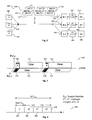
- each transmitter 110, 120, 130 may be transparently connected to each receiver 140, 150, 160.
- Each receiver 140, 150, 160 may receive data 111, 121, 131 from several transmitters 110, 120, 130 in parallel, wherein each transmitter 110, 120, 130 may sent its data on a different wavelength ⁇ 1 , ⁇ 2 , ⁇ 3 . Collisions of data (i.e. the parallel transmission of data at the same wavelength) may be avoided by network management or suitable media access control.
- the selection of data sent from a particular transmitter 110, 120, 130 may be performed by a coherent receiver with an optical local oscillator 141, 151, 161 in combination with an appropriate signal processing 142, 152, 162.
- a receiver 140, 150, 160 may tune its optical local oscillator 141, 151, 161 to the wavelength ⁇ 1 , ⁇ 2 , ⁇ 3 of a selected transmitter 110, 120, 130 and thereby receive the data 111, 121, 131 sent by the selected transmitter 110, 120, 130.
- the targeted network 100 may support the transport of data packets 111, 121, 131.
- the targeted network 100 should have a high spectral efficiency using coherent reception.
- receivers 140, 150, 160 Due to the switching of the receivers 140, 150, 160 between transmitters 110, 120, 130 on a per packet basis (as illustrated by the gray shaded data packets 111, 121, 131 of Fig. 1 ), receiver algorithms which rely on convergence schemes, such as the constant modulus algorithm (CMA), are not appropriate, as they typically require long convergence times.
- CMA constant modulus algorithm
- the optimized training symbol should allow for timing synchronization, frequency- and phase offset estimation between the transmitter laser and the receiver laser (local oscillator), channel estimation and correction, and polarization de-multiplexing for following data symbols.
- the above mentioned tasks should be achieved with high precision.
- the optimized training symbol may be applied to payload data comprising OFDM data or single carrier data. As a result, a sequence of packets 200 may be obtained as illustrated in Fig. 2 .
- Each packet comprises two polarization components x and y., wherein the polarization components comprise payload data 221 and 211 in the two orthogonal polarizations x and y, respectively. Furthermore, the polarization components comprise headers 210, 220 for the x and y polarization, respectively. Theses headers 210, 220 may comprise the training symbols for determining the appropriate parameters for timing synchronization, frequency- and phase offset estimation between the transmitter laser and the receiver laser, channel estimation and correction, and/or polarization de-multiplexing.
- the different packets may comprise payload data in different formats (e.g. different constellations, OFDM vs. single carrier data, different bitrates) on a packet by packet basis.
- OFDM header symbols 210, 220 in combination with payload data 211, 221 enables the quasi instantaneous synchronization of a receiver 140, 150, 160 with an arbitrary transmitter 110, 120, 130, thereby enabling the implementation of highly meshed optical networks 100.
- the optimized training symbol may also be combined with a continuous stream of data, i.e. the optimized training symbol may precede a continuous stream of data.
- the optimized training symbol may ensure a fast adaption of the optical receiver to the transfer function of the optical transmission medium.
- continuous adaption algorithms e.g. the CMA algorithm
- continuous adaption algorithms may be used on the continuous stream of data in order to keep track of modifications of the transfer function.
- the optimized training symbol may be an OFDM based training symbol.
- a timing offset may be modeled as a delay in the received signal and a frequency offset may be modeled as a phase distortion of the received signal in the time domain.
- AWGN additive white Gaussian noise
- this symmetry and/or periodicity may be used at the receiver to determine the timing offset n e and the frequency offset ⁇ e .
- a metric function may be applied to the received signal r [ n ] .
- a maximum or minimum of the metric function may provide an indication of the to-be-estimated parameters.
- an OFDM symbol may comprise two identical sub-sequences A of N / 2 samples, i.e. the time-domain OFDM symbol of N samples may be written as a sequence [A,A] of the two identical sub-sequences A. This means that the time-domain OFDM symbol comprises two identical halves.
- a metric for estimating the frequency offset ⁇ e may be determined. As indicated by the above mentioned formulas, as a result of correlation in the time domain within a sliding window, the exact position of the OFDM symbol inside the received stream of samples can be calculated, independently of a possible frequency shift of the received signal.
- the time-domain OFDM training symbol of N samples may comprise four subsequences [C, D, C*, D*], wherein C* and D* are the conjugate complex of C and D, and wherein C and D have a length of N / 4 samples.
- the sub-sequences C and D may be symmetric with respect to each other.
- This example time-domain OFDM training symbol 300 is illustrated in Fig. 3 , wherein the sub-sequences C (reference numeral 301), D (reference numeral 302), C* (reference numeral 303) and D* (reference numeral 304) are shown.
- a pre-determined structure within the time-domain OFDM training symbol may be used at the receiver to perform timing synchronization, as well as frequency- and phase offset estimation between the transmitter laser and the receiver laser.
- An OFDM training symbol having a pre-determined structure within the time domain may be created by appropriately selecting the information symbols c k of the N OFDM subcarriers.
- pseudo random sequences PRBS
- PRBS pseudo random sequences
- the OFDM training symbol 300 of Fig. 3 may be constructed by calculating an OFDM symbol, in which every second subcarrier is MPSK modulated (while setting to zero the other half of OFDM subcarriers).
- the OFDM training symbols may be extended for polarization multiplexing in optical transmission systems. It is proposed that for each polarization, a different, exclusive set of OFDM subcarriers is used during the construction of the OFDM training symbol. This allows the simultaneous transmission of two symbols 210, 220, one on each polarization plane, as shown in Fig. 2 . By doing this, the time domain properties of each of the superimposed OFDM symbols 210, 220 are maintained. This means that the pre-determined structure of the time-domain OFDM training symbol is maintained, such that the OFDM training symbol may also be used for timing offset and frequency offset compensation.
- the construction of the two OFDM training symbols using different exclusive sets of OFDM subcarriers is compatible with the design of OFDM training symbols having a pre-determined structure in the time-domain, such that quasi-instantaneous timing synchronization, frequency offset compensation, channel equalization and polarization de-multiplexing can be implemented in parallel using the OFDM training symbols described in the present document.
- the OFDM training symbols having a pre-determined structure within the time domain may be constructed by setting the odd OFDM subcarriers to zero, i.e. by only considering the even OFDM subcarriers. From the even OFDM subcarriers a first sub-set of OFDM subcarriers may be assigned to the OFDM training symbol for the first polarization and a second sub-set of OFDM subcarriers may be assigned to the OFDM training symbol for the second polarization (which is typically orthogonal to the first polarization).
- the OFDM subcarriers k 2,6,10,..., i.e.
- the first and the second OFDM training symbols 210, 220 may be separated in the frequency domain, e.g. after FFT of the received signal.
- a 2x2 MIMO (multiple input, multiple output) matrix for polarization de-multiplexing and further channel equalization can be estimated.
- the coefficients H h 11 h 12 h 21 h 22 of the polarization de-multiplexer may be determined.
- OFDM training symbols 210, 220 are preceding every data transmission 211, 221.
- the OFDM training symbols 210, 220 may be repeated periodically for better tracking of channel parameters inside the receiver 140, 150, 160 by interpolating the matrix coefficients h ij between two training symbols.
- the usage of OFDM training symbols 210, 220 which have been generated using different, exclusive sets of subcarriers, allows for the transmission of a different symbol on each polarization at the same time (i.e. in parallel).
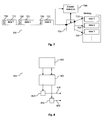
- Fig. 8 illustrates an example block diagram of a system or module 800 which may be used within an optical transmitter.
- the first 210 and second 220 OFDM training symbols may be generated within the OFDM symbol generation unit 801.
- the first and second OFDM training symbols are then combined with first and second payload data, respectively.
- the first and second combined data is then modulated onto optical signals in the modulation units 803, 804, respectively.
- the optical signals have a first and a second polarization, wherein the first and second polarization planes are orthogonal with respect to each other.
- a first signal component 810 and a second signal component 802 are obtained, wherein the first and second signal components have polarizations which are orthogonal with respect to one another.
- data packets as shown in Fig. 2 may be obtained.
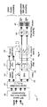
- Fig. 4 illustrates an example block diagram of a coherent optical receiver 400.
- a pair of (complex-valued) digital signals representing the polarization multiplexed optical signal, may be determined.
- This pair of digital signals is submitted to two different paths for signal processing. The first path is directed at the OFDM header processing, and the second path is directed at the processing of the payload data, e.g. the single carrier PDM-QAM signal.
- single carrier PDM-QAM is only an example, and that the OFDM header processing can be combined with any suitable data modulation and the respective processing of the payload data, e.g. PDM-MPSK (phase shift keying of order M) or OFDM.
- PDM-MPSK phase shift keying of order M
- OFDM OFDM
- the header processing starts upon the detection of the OFDM header symbols 210, 220.
- the receiver 400 may analyze the received data stream in order to identify an OFDM header symbol 210, 220 based on its pre-determined structure.
- the OFDM header symbols 210, 220 may be transmitted on a regular/ periodic basis, such that the receiver 400 may expect the OFDM header symbols 210, 220 at regular intervals or subject to a trigger event.
- the receiver uses information derived from the subcarriers of the OFDM symbols.
- the header processing has determined the time offset to, the frequency offset f 0 and/or the de-multiplexing coefficients, the determined information is applied to the signal processing of the payload data, e.g. the PDM-QAM data symbols. This is performed in a timing synchronization unit 403, a frequency offset compensation unit 404 and a polarization de-multiplexing unit 405, respectively. Because all relevant information for correct processing in the receiver 400 is available after the header processing in units 413, 414, 415, the receiver 400 adapts quasi instantaneous to the data burst.
- the payload data processing may comprise an equalization unit 406 and a decision unit 407 to recover the data from the pair of digital signals.
- the proposed method of header insertion can be combined with pilot symbols or pilot subcarriers inside the data block.
- the payload data may comprise additional pilot symbols or pilot subcarriers for the tracking of fast changing channel parameters like laser phase noise, polarization etc., in-between two OFDM header symbols 210, 220.
- the random or periodic repetition of the OFDM header symbol inside a data block or at the end of a data block may be used to support the tracking of channel variations at the receiver side.
- the subcarrier modulation within the OFDM header symbols may be used for signaling purposes.
- the modulation of the subcarriers may be used to transmit information about the subsequent payload data packet(s) (such as address information, modulation format etc.) or as an independent data channel, e.g. for network management information or low data rate user data.
- a receiver 140 is capable to adapt quickly to the data bursts 111, 121, 131 coming from different transmitters 110, 120, 130 with variations in symbol timing and/or wavelength and/or polarization.
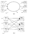
- other topologies like a fiber ring topology 500 comprising a fiber ring 500 (see Fig. 5 ) or fully meshed networks 600 (see Fig. 6 ) are applicable as well.
- Another application for the proposed header insertion scheme is the slicing of a data stream as shown in Fig. 7 .
- Different data packets comprising an OFDM header symbol 710, 720, 730 and payload data 711, 721, 731 are received.
- the detection of the OFDM headers 710, 720, 730 triggers the storage of the corresponding data bursts 711, 721, 731 in respective storages 712, 722, 732 in memory.
- the slicing scenario 700 comprises a header detection unit 740 and a slicing unit 750.
- the data bursts 711, 721, 731 can be processed, e.g. for demodulation and forward error correction decoding.
- the I- and Q-component of pre-calculated QAM-modulated data burst signals are stored in the memory of an 10 GSa/s arbitrary waveform generator (AWG), which outputs drive a nested I/Q-modulator.
- AMG arbitrary waveform generator
- Polarization diverse multiplexing may be emulated by splitting and recombining the signal with orthogonal polarization with a delay of 27 ns.
- an independent second laser may be used as local oscillator (LO). The light of the received signal and LO is superimposed in a polarization diverse 90°-hybrid 401.
- the output signals of the four balanced photo detectors are digitized with a realtime sampling scope at 12.5 GSa/s and transferred to a PC for the receiver signal processing depicted in Fig. 4 .
- the nominal resolution of AWG and sampling scope may be 8 bit.
- the symbol rate for the performance measurements may be 2.5 Gbaud/s, thus a data rate of 25 Gb/s for PDM-32QAM and 30 Gb/s for PDM-64QAM formats could be achieved.
- Fig. 4 The digital signal processing at the receiver is depicted Fig. 4 .
- every data burst is preceded by an OFDM synchronization symbol 210, 220 with a length of 27 ns.
- 88 out of 256 subcarriers are distributed on the two orthogonal polarizations.
- the subcarriers are used to detect the beginning of a data burst, to calculate the frequency offset of transmitter laser and LO and for channel estimation including the 2x2 matrix coefficients for polarization de-multiplexing of the data symbols.
- the single carrier PDM-QAM data symbols are processed.
- the necessary parameters for time synchronization, frequency conversion and polarization de-multiplexing are derived from the OFDM synchronization symbols in the units 413, 414, 415.
- the frequency offset and the orientation of polarization may typically be treated as constant during the data burst of 9216 symbols.
- the phase drift between transmitter and LO should be tracked and compensated. This may be achieved by a PID-control loop for the symbols phase, with a decision feed back on a symbol-by-symbol basis.
- an adaptive equalizer with 17 tap FIR filters 406 may be used on each data stream separately.
- a matched root raised cosine filter for pulse shaping may be included during up- and down sampling in the transmitter and receiver, respectively.
- the processing of the single carrier PDM-QAM data symbols at the receiver does not depend on a certain modulation constellation.
- This allows the use of differently shaped constellations without variation of the receiver algorithm.
- rectangular QAM-constellations in cross and square shape, hexagonal shaped constellations, which allow for the most compact packing of constellation points within a given area, and/or round ring constellations, with low peak-to-average ratio and increased density of points in the middle of the constellation may be used for the payload data.
- a burst mode capable transmission system with an OFDM based, data independent synchronization symbol for a fast adaption of the receiver has been described.
- the implemented receiver algorithms allow the transmission of arbitrary shaped QAM constellations with up to 64 states in polarization division multiplex.
- symbol error rate vs. OSNR By measurement of symbol error rate vs. OSNR, a square, hexagonal and round shaped types of constellation diagrams with 32 and 64 states have been compared. It can be shown that round constellation shapes show a benefit of up to 3 dB in the noise limited regime.
- PDM-32 QAM round constellations allow error free transmission, if the system is limited by hardware constraints like resolution of the converters and phase noise.
- 64-QAM the error floor of the system may significantly be reduced by the usage of non-square constellation shapes.
- the OFDM training symbols may be specifically designed to allow for a fast synchronization of a timing offset and a frequency offset.
- the OFDM training symbols are appropriately designed to allow for fast (e.g. quasi instantaneous) polarization de-multiplexing of polarization multiplexed optical signals.
- the OFDM synchronization headers allow for the implementation of fast adapting receivers.
- additional information like address labels, may be inserted into the OFDM headers. Consequently, quick adapting coherent optical receivers can be implemented which allow for new optical network concepts, e.g. network concepts based on burst mode transmission using spectral efficient PDM-QAM.
- steps of various above-described methods and modules of described systems can be performed by programmed computers.
- program storage devices e.g., digital data storage media, which are machine or computer readable and encode machine-executable or computer-executable programs of instructions, wherein said instructions perform some or all of the steps of said above-described methods.
- the program storage devices may be, e.g., digital memories, magnetic storage media such as a magnetic disks and magnetic tapes, hard drives, or optically readable digital data storage media.
- the embodiments are also intended to cover computers programmed to perform said steps of the above-described methods.
- processor or “controller” should not be construed to refer exclusively to hardware capable of executing software, and may implicitly include, without limitation, digital signal processor (DSP) hardware, network processor, application specific integrated circuit (ASIC), field programmable gate array (FPGA), read only memory (ROM) for storing software, random access memory (RAM), and non volatile storage.
- DSP digital signal processor
- ASIC application specific integrated circuit
- FPGA field programmable gate array
- ROM read only memory
- RAM random access memory
- non volatile storage Other hardware, conventional and/or custom, may also be included.
- any block diagrams herein represent conceptual views of illustrative circuitry embodying the principles of the invention.
- any flow charts, flow diagrams, state transition diagrams, pseudo code, and the like represent various processes which may be substantially represented in computer readable medium and so executed by a computer or processor, whether or not such computer or processor is explicitly shown.
Landscapes
- Engineering & Computer Science (AREA)
- Signal Processing (AREA)
- Computer Networks & Wireless Communication (AREA)
- Power Engineering (AREA)
- Physics & Mathematics (AREA)
- Electromagnetism (AREA)
- Optical Communication System (AREA)
Abstract
Description
- The present document relates to optical transmission. In particular, the present document relates to the synchronisation and adaption of a coherent optical receiver for polarisation division multiplexed (PDM) transmission systems.
- In optical transmission systems using coherent optical receivers, digital signal processors which may comprise equalization filters and/or de-polarization filters may be used to compensate for linear and non-linear distortions incurred by the optical signal over the transmission medium. The distortions which are caused by the transmission medium may typically be described by a transfer function of the transmission medium. Blind adaption of the optical receiver may be used to determine the coefficients of the equalization and/or de-polarization filters. The blind adaption may make use of a constant- or multimodulus algorithm. However, the use of blind adaption typically requires long training sequences (e.g. several 1000 symbols) in order to converge to appropriate coefficients of the equalization filters and/or de-polarization filters. Furthermore, the receiver typically requires a continuous data stream in order to stay synchronized with modifications to the transfer function of the transmission medium. In addition, due to the long trainings phases of the receiver when using blind adaption, the switching of a receiver between different transmitters is usually not efficient.
- The present document addresses the above mentioned shortcomings with respect to the synchronisation and adaption of a (coherent) optical receiver.
- According to an aspect a transmitter or a module for a transmitter of an optical polarization division multiplexed (PDM) signal is described. The module for the transmitter may e.g. be a transmitter sub-assembly or sub-system. The PDM signal usually comprises a first signal component in a first optical polarization plane and a second signal component in a second optical polarization plane. The first and second optical polarization planes may be orthogonal with respect to each other.
- The transmitter or the module for a transmitter typically comprises a symbol generation unit (also referred to as header generation unit) which is configured to generate a first OFDM symbol and a second OFDM symbol. Furthermore, the transmitter or the module for a transmitter usually comprises a symbol insertion unit (also referred to as header insertion unit) adapted to adjoin the first OFDM symbol to first payload data for transmission in the first signal component, and adapted to adjoin the second OFDM symbol to second payload data for transmission in the second signal component. In other words, the transmitter or the module for a transmitter is adapted to add a first and second OFDM symbol as headers to first and second payload data, respectively. By generating first and second OFDM symbols which comprise mutually exclusive sets of OFDM subcarriers, the first and second OFDM symbols can be used for quasi instantaneous polarization de-multiplexing of the first and second signal components at a corresponding receiver. Furthermore, the use of OFDM header symbols allows for quasi instantaneous timing synchronization, frequency offset compensation and/or channel equalization, as will be outlined in the following.
- As indicated above, the symbol generation unit is typically configured to generate a first OFDM symbol and a second OFDM symbol. The first and/or second OFDM symbols may comprise N samples, and the first and/or second OFDM symbols may comprise N OFDM subcarriers. In order to enable fast polarization de-multiplexing at the corresponding receiver, the first and second OFDM symbols usually comprise mutually exclusive sets of OFDM subcarriers. In other words, the first and second OFDM symbols may comprise mutually exclusive frequency components, i.e. the first OFDM symbol may comprise frequency components which are not comprised within the second OFDM symbol and vice versa. The mutually exclusive sets of OFDM subcarriers comprise a first set for the first OFDM symbol and a second set for the second OFDM symbol. As such, the first set of OFDM subcarriers may comprise subcarriers which are not comprised within the second set of OFDM subcarriers and vice versa. By way of example, a first half of the N OFDM subcarriers is comprised within the first set and the other half of the N OFDM subcarriers is comprised within the second set. In particular, the first and second set of OFDM subcarriers may be interleaved, such that - in an example - every second OFDM subcarrier is assigned to the first set and the remaining OFDM subcarriers are assigned to the second set.
- As will be outlined in the following, it may be advantageous to generate OFDM symbols which have a pre-determined structure in the time-domain, wherein the pre-determined structure enables the corresponding receiver to perform timing synchronization, frequency offset compensation and/or channel equalization. In order to generate an appropriate pre-determined structure, it may be advantageous to set the even or odd OFDM subcarriers to zero. In this case, the first and second set of OFDM subcarriers are selected from the OFDM subcarriers which are not set to zero. In a particular example, the odd OFDM subcarriers are set to zero and the first set of OFDM subcarriers comprises the OFDM subcarriers 2+4*k and the second set of OFDM subcarriers comprises the OFDM subcarriers 4*k, with k=0,...,N/4-1.
- The symbol generation unit may be configured to select amplitudes of the OFDM subcarriers comprised within the first and/or second OFDM symbols. By way of example, the amplitude of the odd or even OFDM subcarriers may be set to zero. In this case, only half of the available OFDM subcarriers have non-zero amplitudes. Alternatively or in addition, the phase of the non-zero OFDM subcarriers (i.e. first and/or second set of OFDM subcarriers) may be MPSK (mary phase-shift keying) modulated (e.g. 2PSK with a phase of 0 or π) with data selected from a pseudo-random sequence. As a result of appropriately selecting the amplitudes and/or phase of the OFDM subcarriers, the first and/or second OFDM symbols can be provided with a pre-determined structure in the time-domain. As outlined above, the pre-determined structure in the time-domain enables a corresponding receiver to perform quasi-instantaneous timing synchronization, frequency offset compensation and/or channel equalization.
- Furthermore, by appropriately selecting and/or modulating the amplitudes and/or phase of the first and/or second OFDM symbols, the first and/or second OFDM symbols can be used to carry signaling information (e.g. information regarding the subsequent payload data such as addressing information and/or modulation format information).
- As outlined above, the symbol insertion unit is typically configured to adjoin or to add the first OFDM symbol to first payload data for transmission in the first signal component. Furthermore, the symbol insertion unit is typically configured to adjoin or add the second OFDM symbol to second payload data for transmission in the second signal component. In other words, the symbol insertion unit is configured to add the first and/or second OFDM symbol as a header to first and/or second payload data, respectively. The first and/or second payload data may be OFDM data and/or single carrier data. As such, the first and second OFDM symbol can be combined with a large variety of payload data. By way of example, the first and/or second payload data may be a continuous data stream or a data packet. In view of the quasi instantaneous convergence of the corresponding receiver to the received data, data packets comprising OFDM header symbols can be used to implement packet switched optical networks.
- In addition, the first and/or second payload data may comprise a pilot symbol and/or a pilot subcarrier for enabling equalization at a corresponding receiver. In particular, a pilot symbol and/or a pilot subcarrier within the payload data can be used to enable the continuous adjustment of the receiver parameters.
- The symbol insertion unit may be configured to periodically adjoin or add a first and/or a second OFDM symbol to the first and/or second payload data, respectively. If the payload data is arranged in data packets, the symbol insertion unit may be configured to add a first and/or second OFDM symbol as a header to some (e.g. every Mth packet, M=1,....,10) or all data packets.
- As indicated above, the first and/or second OFDM symbols may be provided with a pre-determined structure in the time-domain, in order to enable quasi instantaneous timing synchronization, frequency offset compensation and/or channel equalization. In this case, the symbol generation unit is configured to generate the first OFDM symbol and the second OFDM symbol having a predetermined structure in the time domain. Typically, this is achieved by appropriately modulating the OFDM subcarriers or by appropriately selecting the amplitudes and/or phase of the OFDM subcarriers. The pre-determined structure may comprise a symmetry in time domain of one or more subgroups of the N samples of the OFDM symbol, a periodic repetition in time domain of one or more identical subgroups of the N samples of the OFDM symbol, and/or complex conjugation of one or more subgroups of the N samples of the OFDM symbol. By way of example, the pre-determined structure of the samples of the first and/or second OFDM symbol in the time domain is [A, A], wherein A is a subsequence of N/2 samples of the first and/or second OFDM symbol. Alternatively, the predetermined structure in the time domain is [C, D, C*, D*], wherein C and D are subsequences of N/4 samples of the first and/or second OFDM symbol, and wherein C* and D* are complex conjugates of C and D, respectively. As outlined above, the selection of an appropriate structure of the first and/or second OFDM symbol in the time domain can be used at a corresponding receiver for timing synchronization, frequency offset determination and compensation and/or channel equalization tasks.
- According to a further aspect, a receiver or a module for a receiver of an optical polarization division multiplexed (PDM) signal is described. The receiver or the module for the receiver may e.g. be a receiver sub-assembly or sub-system. As outlined above, the PDM signal may comprise a first signal component in a first optical polarization plane and a second signal component in a second optical polarization plane. The first and second optical polarization planes may be orthogonal with respect to each other. The first signal component may comprise a first OFDM symbol preceding first payload data. The second signal component may comprise a second OFDM symbol preceding second payload data.
- The receiver or the module for a receiver may comprise a channel estimation unit configured to determine coefficients of a polarization de-multiplexer. The polarization de-multiplexer may be configured to isolate the first and second signal components from the PDM signal. In other words, the polarization de-multiplexer may be configured to rotate the PDM signal, in order to identify the first and second polarization plane and to thereby isolate the first and second signal components of the PDM signal. For this purpose, the polarization de-multiplexer may comprise a 2x2 multiple-in-multiple-out (MIMO) filter structure with four FIR filters, wherein each FIR filter may have a predetermined number of coefficients (e.g. 1, 2, 3, 4, 5, 6, 7 coefficients). In other words, the polarization de-multiplexer may apply a matrix

- The channel estimation unit may be configured to determine the coefficients based on the fact or using the fact that, at a corresponding transmitter, the first and second OFDM symbols comprised mutually exclusive sets of OFDM subcarriers. In other words, the channel estimation unit may exploit the fact that the first and second OFDM symbols have been generated and inserted by a transmitter or a module for a transmitter of a PDM signal as outlined above. In particular, the channel estimation unit may be configured to determine the four filter coefficients as the coefficients of the two by two rotation matrix which transform the first and second OFDM symbols at the receiver into the first and second OFDM symbols at the transmitter.
- As outlined above, the first and/or second OFDM symbols may have a predetermined structure in the time-domain. The receiver or the module for the receiver may comprise subunits which make use of the pre-determined structure for time synchronization and/or frequency offset compensation purposes. In particular, the receiver may comprise a symbol detection unit configured to determine a time offset using the pre-determined structure of the first and/or second OFDM symbols. In addition, the receiver may comprise a timing synchronization unit configured to time-synchronize the reception of the first and/or second payload data using the timing offset. Alternatively or in addition, the receiver may comprise a frequency offset determination unit configured to determine a frequency offset using the pre-determined structure of the first and/or second OFDM symbols. Furthermore, the receiver may comprise a frequency offset compensation unit configured to compensate a frequency offset of a local oscillator (LO) carrier used for the reception of the first and/or second payload data with a coherent optical receiver.
- According to a further aspect, an optical polarization division multiplexed (PDM) signal comprising a first signal component in a first optical polarization plane and a second signal component in a second optical polarization plane is described. The first and second optical polarization planes may be orthogonal with respect to each other. The first signal component may comprise a first OFDM symbol followed by first payload data. The second signal component may comprise a second OFDM symbol followed by second payload data. The first and second OFDM symbols may comprise mutually exclusive sets of OFDM subcarriers. In other words, the first OFDM symbol may comprise OFDM subcarriers which are not comprised within the second OFDM symbol and vice versa.
- According to another aspect, a method for enabling polarization de-multiplexing of an optical polarization division multiplexed (PDM) signal is described. The method is typically executed at a transmitter of an optical transmission network. The method may comprise generating a first OFDM symbol and a second OFDM symbol. The first and second OFDM symbols may comprise mutually exclusive sets of OFDM subcarriers. Furthermore, the method may comprise adding the first OFDM symbol to first payload data for transmission in a first signal component of the PDM signal, and/or adding the second OFDM symbol to second payload data for transmission in a second signal component of the PDM signal. The first and second signal components may be transmitted on optical polarization planes which are orthogonal with respect to each other.
- According to another aspect, a method for performing polarization de-multiplexing of an optical polarization division multiplexed (PDM) signal is described. The method is typically executed at an optical receiver of an optical transmission network. The PDM signal may comprise a first signal component in a first optical polarization plane and a second signal component in a second optical polarization plane. The first and second optical polarization planes may be orthogonal with respect to each other. The first signal component may comprise a first OFDM symbol as a header to first payload data. The second signal component may comprise a second OFDM symbol as a header to second payload data. The method may comprise determining coefficients of a polarization de-multiplexer for isolating the first and second signal components from the PDM signal. The coefficients may be determined using the fact that, at a corresponding transmitter, the first and second OFDM symbols comprised mutually exclusive sets of OFDM subcarriers.
- According to a further aspect, a software program is described. The software program may be stored on a computer-readable medium (which may be tangible or otherwise non-transitory) as instructions that are adapted for execution on a processor and for performing the aspects and features outlined in the present document when carried out on a computing device.
- According to another aspect, a storage medium comprising a software program is described. The storage medium may be memory (e.g. RAM, ROM, etc.), optical media, magnetic media and the like. The software program may be adapted for execution on a processor and for performing the aspects and features outlined in the present document when carried out on a computing device.
- According to a further aspect, a computer program product is described. The computer program product may comprise executable instructions for performing the aspects and features outlined in the present document when executed on a computing device.
- It should be noted that the methods and systems or modules including its preferred embodiments as outlined in the present document may be used stand-alone or in combination with the other methods and systems or modules disclosed in this document. Furthermore, all aspects of the methods and systems or modules outlined in the present document may be arbitrarily combined. In particular, the features of the claims may be combined with one another in an arbitrary manner.
- The invention is explained below in an exemplary manner with reference to the accompanying drawings, wherein
-
Fig. 1 illustrates an example time division multiplexing (TDM) system with multiple transmitters and fast adapting receiver; -
Fig. 2 shows an example for the insertion of OFDM header symbols into data streams; -
Fig. 3 shows an example OFDM header sequence; -
Fig. 4 illustrates an example block diagram of the signal processing at the receiver on the header path and on the data path; -
Fig. 5 shows an example TDM/WDM (wavelength division multiplexing) system on a fiber ring; -
Fig. 6 shows an example TDM/WDM system in fully meshed network topology; -
Fig. 7 illustrates an example block diagram of the usage of header detection to separate a data stream into blocks for further processing, e.g. for forward error correction (FEC), in memory; and -
Fig. 8 illustrates an example block diagram of a system for an optical transmitter. - In optical telecommunication, it may be desirable to provide a highly meshed
optical network 100 withM transmitters N receivers Fig. 1 . Eachtransmitter receiver receiver data several transmitters transmitter receiver particular transmitter local oscillator appropriate signal processing receiver local oscillator transmitter data transmitter network 100 may support the transport ofdata packets network 100 should have a high spectral efficiency using coherent reception. Due to the switching of thereceivers transmitters data packets Fig. 1 ), receiver algorithms which rely on convergence schemes, such as the constant modulus algorithm (CMA), are not appropriate, as they typically require long convergence times. - In order to overcome the above mentioned shortcomings of conventional coherent receivers and in order to allow for switched, fully meshed optical networks, it is proposed to make use of an optimized training symbol. The optimized training symbol should allow for timing synchronization, frequency- and phase offset estimation between the transmitter laser and the receiver laser (local oscillator), channel estimation and correction, and polarization de-multiplexing for following data symbols. The above mentioned tasks should be achieved with high precision. The optimized training symbol may be applied to payload data comprising OFDM data or single carrier data. As a result, a sequence of
packets 200 may be obtained as illustrated inFig. 2 . Each packet comprises two polarization components x and y., wherein the polarization components comprisepayload data headers Theses headers OFDM header symbols payload data receiver arbitrary transmitter optical networks 100. - It should be noted that the optimized training symbol may also be combined with a continuous stream of data, i.e. the optimized training symbol may precede a continuous stream of data. As such, the optimized training symbol may ensure a fast adaption of the optical receiver to the transfer function of the optical transmission medium. Subsequent, continuous adaption algorithms (e.g. the CMA algorithm) may be used on the continuous stream of data in order to keep track of modifications of the transfer function.
- The optimized training symbol may be an OFDM based training symbol. An OFDM symbol at the
transmitter 
where N is the number of OFDM sub-carriers and the ck are the complex information symbols. The time domain OFDM signal is transmitted over the optical transmission channel having a channel impulse response h[m] , thereby yielding the OFDM signal after having passed through the transmission channel
where L denotes the memory of the channel impulse response. - At the
receiver 
where ne is the (possibly integer-valued) unknown arrival time of the OFDM symbol, θe is the frequency offset, ø is the initial phase and w[n] is the AWGN. - It may be shown that when using a symmetry and/or periodicity within the time-domain OFDM training symbol, this symmetry and/or periodicity may be used at the receiver to determine the timing offset ne and the frequency offset θe . For this purpose, a metric function may be applied to the received signal r[n] . A maximum or minimum of the metric function may provide an indication of the to-be-estimated parameters. By way of example, an OFDM symbol may comprise two identical sub-sequences A of N / 2 samples, i.e. the time-domain OFDM symbol of N samples may be written as a sequence [A,A] of the two identical sub-sequences A. This means that the time-domain OFDM symbol comprises two identical halves. A metric

with
and
may be used to identify the parameter d which maximizes the metric M(d) and thereby provides an estimate of the timing offset ne. In a similar manner, a metric for estimating the frequency offset θ e may be determined. As indicated by the above mentioned formulas, as a result of correlation in the time domain within a sliding window, the exact position of the OFDM symbol inside the received stream of samples can be calculated, independently of a possible frequency shift of the received signal. - More complex pre-determined structures of the time-domain OFDM training symbol may be used to improve the quality of the estimates of the timing offset and the frequency offset. By way of example, the time-domain OFDM training symbol of N samples may comprise four subsequences [C, D, C*, D*], wherein C* and D* are the conjugate complex of C and D, and wherein C and D have a length of N / 4 samples. The sub-sequences C and D may be symmetric with respect to each other. This example time-domain
OFDM training symbol 300 is illustrated inFig. 3 , wherein the sub-sequences C (reference numeral 301), D (reference numeral 302), C* (reference numeral 303) and D* (reference numeral 304) are shown. - The use of OFDM signals having a pre-determined in the time-domain has been described in the context of OFDM radio transmission in Park e.a., "A Novel Timing Estimation Method for OFDM Systems", IEEE Comm. Letters, Vol. 7, pp. 239-241, May 2003; and Schmidl, Cox, "Robust frequency and timing synchronization for OFDM," IEEE Trans. Commun., vol. 45, pp. 1613-1621, Dec. 1997. These documents are incorporated by reference.
- As such, a pre-determined structure (e.g. a symmetry and/or a periodicity) within the time-domain OFDM training symbol may be used at the receiver to perform timing synchronization, as well as frequency- and phase offset estimation between the transmitter laser and the receiver laser. An OFDM training symbol having a pre-determined structure within the time domain may be created by appropriately selecting the information symbols ck of the N OFDM subcarriers. By way of example, pseudo random sequences (PRBS) may be transmitted on the even OFDM subcarrier frequencies and zeros may be transmitted on the odd OFDM subcarrier frequencies to provide the OFDM training symbol [A, A] comprising two equal halves in the time-domain. Alternatively, the
OFDM training symbol 300 ofFig. 3 may be constructed by calculating an OFDM symbol, in which every second subcarrier is MPSK modulated (while setting to zero the other half of OFDM subcarriers). - The OFDM training symbols may be extended for polarization multiplexing in optical transmission systems. It is proposed that for each polarization, a different, exclusive set of OFDM subcarriers is used during the construction of the OFDM training symbol. This allows the simultaneous transmission of two
symbols Fig. 2 . By doing this, the time domain properties of each of the superimposedOFDM symbols - As outlined above, the OFDM training symbols having a pre-determined structure within the time domain may be constructed by setting the odd OFDM subcarriers to zero, i.e. by only considering the even OFDM subcarriers. From the even OFDM subcarriers a first sub-set of OFDM subcarriers may be assigned to the OFDM training symbol for the first polarization and a second sub-set of OFDM subcarriers may be assigned to the OFDM training symbol for the second polarization (which is typically orthogonal to the first polarization). By way of example, the OFDM subcarriers k = 2,6,10,..., i.e. the OFDM subcarriers 2+4*k with k=0,..., N/4-1, may be used to generate the first
OFDM training symbol 210 for the first polarization and the OFDM subcarriers k = 0,4,8,12,..., i.e. theOFDM subcarriers 4*k, with k=0,...,N/4-1, may be used to generate the secondOFDM training symbol 220 for the second polarization. - At the receiver, the first and the second
OFDM training symbols 
- By way of example, a first
OFDM training symbol 210 may comprise the OFDM subcarriers k=2, 6, 10 ...., i.e. thefirst OFDM symbol 210 at the transmitter may be written as
- The
second OFDM symbol 220 may comprise the OFDM subcarriers k=0, 4, 8, ...., i.e. thesecond OFDM symbol 220 at the transmitter may be written as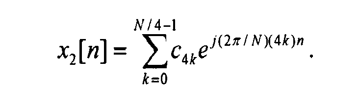
- The first and second OFDM training symbols at the receiver may be written as

and

and

polarization de-multiplexer by
- This results in an array of equations in the frequency domain, i.e.


from which appropriate values for the matrix
- To achieve better accuracy for polarization de-multiplexing and channel equalization the implementation of the coefficients hij as FIR-filter structures instead of a single complex number may be appropriate.
- Consequently, suitably constructed OFDM symbols are inserted into the data stream, in order to allow for a fast synchronization of the
optical receiver Fig. 2 , theOFDM training symbols data transmission OFDM training symbols receiver OFDM training symbols -
Fig. 8 illustrates an example block diagram of a system ormodule 800 which may be used within an optical transmitter. The first 210 and second 220 OFDM training symbols may be generated within the OFDMsymbol generation unit 801. Using asymbol insertion unit 802, the first and second OFDM training symbols are then combined with first and second payload data, respectively. The first and second combined data is then modulated onto optical signals in themodulation units first signal component 810 and asecond signal component 802 are obtained, wherein the first and second signal components have polarizations which are orthogonal with respect to one another. As a result, data packets as shown inFig. 2 may be obtained. -
Fig. 4 illustrates an example block diagram of a coherentoptical receiver 400. Using a 90°-Hybrid, and optical front end and analog to digital (AD) converters inunit 401, as well as asignal restoration unit 402, a pair of (complex-valued) digital signals, representing the polarization multiplexed optical signal, may be determined. This pair of digital signals is submitted to two different paths for signal processing. The first path is directed at the OFDM header processing, and the second path is directed at the processing of the payload data, e.g. the single carrier PDM-QAM signal. It should be noted that single carrier PDM-QAM is only an example, and that the OFDM header processing can be combined with any suitable data modulation and the respective processing of the payload data, e.g. PDM-MPSK (phase shift keying of order M) or OFDM. - Typically, the header processing starts upon the detection of the
OFDM header symbols OFDM header symbols receiver 400 may analyze the received data stream in order to identify anOFDM header symbol OFDM header symbols receiver 400 may expect theOFDM header symbols - If the
OFDM header symbols symbol detection unit 413, the frequency offsetdetermination unit 414 and thechannel estimation unit 415, respectively. For this purpose, the receiver uses information derived from the subcarriers of the OFDM symbols. - Once, the header processing has determined the time offset to, the frequency offset f0 and/or the de-multiplexing coefficients, the determined information is applied to the signal processing of the payload data, e.g. the PDM-QAM data symbols. This is performed in a
timing synchronization unit 403, a frequency offsetcompensation unit 404 and apolarization de-multiplexing unit 405, respectively. Because all relevant information for correct processing in thereceiver 400 is available after the header processing inunits receiver 400 adapts quasi instantaneous to the data burst. In addition, the payload data processing may comprise anequalization unit 406 and adecision unit 407 to recover the data from the pair of digital signals. - It should be noted that the proposed method of header insertion can be combined with pilot symbols or pilot subcarriers inside the data block. This means that the payload data may comprise additional pilot symbols or pilot subcarriers for the tracking of fast changing channel parameters like laser phase noise, polarization etc., in-between two
OFDM header symbols - The subcarrier modulation within the OFDM header symbols may be used for signaling purposes. By way of example, the modulation of the subcarriers may be used to transmit information about the subsequent payload data packet(s) (such as address information, modulation format etc.) or as an independent data channel, e.g. for network management information or low data rate user data.
- As outlined above, the proposed approach of OFDM header insertion may be applied to
TDM systems 100 withunsynchronized transmitters Fig. 1 . With the aid of the OFDM header symbols, areceiver 140 is capable to adapt quickly to the data bursts 111, 121, 131 coming fromdifferent transmitters fiber ring topology 500 comprising a fiber ring 500 (seeFig. 5 ) or fully meshed networks 600 (seeFig. 6 ) are applicable as well. - Another application for the proposed header insertion scheme is the slicing of a data stream as shown in
Fig. 7 . Different data packets comprising anOFDM header symbol payload data OFDM headers respective storages slicing scenario 700 comprises aheader detection unit 740 and aslicing unit 750. Subsequent to slicing and storage, the data bursts 711, 721, 731 can be processed, e.g. for demodulation and forward error correction decoding. - By the introduction of an OFDM-based, data independent synchronization symbol, a burst mode capable coherent transmission system may be implemented. Experimental comparison of differently shaped 32-/64-QAM-constellations shows a benefit of up to 3dB in OSNR-sensitivity for round constellation patterns.
- For the experimental setup, the I- and Q-component of pre-calculated QAM-modulated data burst signals are stored in the memory of an 10 GSa/s arbitrary waveform generator (AWG), which outputs drive a nested I/Q-modulator. Polarization diverse multiplexing may be emulated by splitting and recombining the signal with orthogonal polarization with a delay of 27 ns. At the receiver an independent second laser may be used as local oscillator (LO). The light of the received signal and LO is superimposed in a polarization diverse 90°-
hybrid 401. The output signals of the four balanced photo detectors are digitized with a realtime sampling scope at 12.5 GSa/s and transferred to a PC for the receiver signal processing depicted inFig. 4 . The nominal resolution of AWG and sampling scope may be 8 bit. The symbol rate for the performance measurements may be 2.5 Gbaud/s, thus a data rate of 25 Gb/s for PDM-32QAM and 30 Gb/s for PDM-64QAM formats could be achieved. - The digital signal processing at the receiver is depicted
Fig. 4 . To allow a fast adaption of the receiver, every data burst is preceded by anOFDM synchronization symbol - In a second path, the single carrier PDM-QAM data symbols are processed. The necessary parameters for time synchronization, frequency conversion and polarization de-multiplexing are derived from the OFDM synchronization symbols in the
units - Due to the introduction of an independent OFDM synchronization symbol, the processing of the single carrier PDM-QAM data symbols at the receiver does not depend on a certain modulation constellation. This allows the use of differently shaped constellations without variation of the receiver algorithm. By way of example, rectangular QAM-constellations in cross and square shape, hexagonal shaped constellations, which allow for the most compact packing of constellation points within a given area, and/or round ring constellations, with low peak-to-average ratio and increased density of points in the middle of the constellation may be used for the payload data.
- As such, a burst mode capable transmission system with an OFDM based, data independent synchronization symbol for a fast adaption of the receiver has been described. The implemented receiver algorithms allow the transmission of arbitrary shaped QAM constellations with up to 64 states in polarization division multiplex. By measurement of symbol error rate vs. OSNR, a square, hexagonal and round shaped types of constellation diagrams with 32 and 64 states have been compared. It can be shown that round constellation shapes show a benefit of up to 3 dB in the noise limited regime. For PDM-32 QAM round constellations allow error free transmission, if the system is limited by hardware constraints like resolution of the converters and phase noise. For 64-QAM the error floor of the system may significantly be reduced by the usage of non-square constellation shapes.
- In the present document methods and systems for the fast synchronization of optical transmission systems are described. It is proposed to make use of OFDM training symbols in combination with additional payload data. The OFDM training symbols may be specifically designed to allow for a fast synchronization of a timing offset and a frequency offset. Alternatively or in addition, the OFDM training symbols are appropriately designed to allow for fast (e.g. quasi instantaneous) polarization de-multiplexing of polarization multiplexed optical signals. As such, the OFDM synchronization headers allow for the implementation of fast adapting receivers. Furthermore, additional information, like address labels, may be inserted into the OFDM headers. Consequently, quick adapting coherent optical receivers can be implemented which allow for new optical network concepts, e.g. network concepts based on burst mode transmission using spectral efficient PDM-QAM.
- It should be noted that the description and drawings merely illustrate the principles of the proposed methods and systems. It will thus be appreciated that those skilled in the art will be able to devise various arrangements that, although not explicitly described or shown herein, embody the principles of the invention and are included within its spirit and scope. Furthermore, all examples recited herein are principally intended expressly to be only for pedagogical purposes to aid the reader in understanding the principles of the proposed methods and systems and the concepts contributed by the inventors to furthering the art, and are to be construed as being without limitation to such specifically recited examples and conditions. Moreover, all statements herein reciting principles, aspects, and embodiments of the invention, as well as specific examples thereof, are intended to encompass equivalents thereof.
- Furthermore, it should be noted that steps of various above-described methods and modules of described systems can be performed by programmed computers. Herein, some embodiments are also intended to cover program storage devices, e.g., digital data storage media, which are machine or computer readable and encode machine-executable or computer-executable programs of instructions, wherein said instructions perform some or all of the steps of said above-described methods. The program storage devices may be, e.g., digital memories, magnetic storage media such as a magnetic disks and magnetic tapes, hard drives, or optically readable digital data storage media. The embodiments are also intended to cover computers programmed to perform said steps of the above-described methods.
- In addition, it should be noted that the functions of the various elements described in the present patent document may be provided through the use of dedicated hardware as well as hardware capable of executing software in association with appropriate software. When provided by a processor, the functions may be provided by a single dedicated processor, by a single shared processor, or by a plurality of individual processors, some of which may be shared. Moreover, explicit use of the term "processor" or "controller" should not be construed to refer exclusively to hardware capable of executing software, and may implicitly include, without limitation, digital signal processor (DSP) hardware, network processor, application specific integrated circuit (ASIC), field programmable gate array (FPGA), read only memory (ROM) for storing software, random access memory (RAM), and non volatile storage. Other hardware, conventional and/or custom, may also be included.
- Finally, it should be noted that any block diagrams herein represent conceptual views of illustrative circuitry embodying the principles of the invention. Similarly, it will be appreciated that any flow charts, flow diagrams, state transition diagrams, pseudo code, and the like represent various processes which may be substantially represented in computer readable medium and so executed by a computer or processor, whether or not such computer or processor is explicitly shown.
Claims (15)
- A transmitter (110) of an optical polarization division multiplexed, PDM, signal; wherein the PDM signal comprises a first signal component (810) in a first optical polarization plane and a second signal component (820) in a second optical polarization plane; the transmitter (110) comprising- a symbol generation unit (801) adapted to generate a first OFDM symbol (210) and a second OFDM symbol (220); wherein the first (210) and second (220) OFDM symbols comprise mutually exclusive sets of OFDM subcarriers; and- a symbol insertion unit (802) adapted to adjoin the first OFDM symbol (210) to first payload data (211) for transmission in the first signal component (810), and adapted to adjoin the second OFDM symbol (220) to second payload data (221) for transmission in the second signal component (820).
- The transmitter (110) of claim 1, wherein the symbol generation unit (801) is adapted to generate the first OFDM symbol (210) and the second OFDM symbol (220) having a pre-determined structure in the time domain; wherein the pre-determined structure in the time domain is one of:- [A, A]; wherein A is a subgroup of N/2 samples of the first (210) and/or second (220) OFDM symbol; and- [C, D, C*, D*], wherein C and D are subgroups of N/4 samples of the first (210) and/or second (220) OFDM symbol; wherein C* and D* are complex conjugates of C and D, respectively.
- The transmitter (110) of any previous claims, wherein the first (210) and second (220) OFDM symbols comprise N OFDM subcarriers; wherein the mutually exclusive sets of OFDM subcarriers comprise a first set for the first OFDM symbol (210) and a second set for the second OFDM symbol (220);
and wherein an amplitude of the odd OFDM subcarriers is set to zero. - The transmitter (110) of claim 3, wherein the first set of OFDM subcarriers comprises the OFDM subcarriers 2+4*k and the second set of OFDM subcarriers comprises the OFDM subcarriers 4*k, with k=0,...,N/4-1.
- The transmitter (110) of any previous claims, wherein amplitudes and/or phase of the first and/or second set of OFDM subcarriers are any of:- pseudo-random sequences; and- MPSK modulated.
- The transmitter (110) of any previous claims, wherein the first (210) and/or second (220) OFDM symbols carry signaling information and/or user data.
- The transmitter (110) of any previous claims, wherein the symbol insertion unit (802) is adapted to periodically adjoin first (210) and/or second (220) OFDM symbols to the first and/or second payload data.
- The transmitter (110) of any previous claim, wherein the first and/or second payload data comprises a pilot symbol and/or a pilot subcarrier for equalization at a corresponding receiver (400).
- The transmitter (110) of any previous claim, wherein the first and/or second payload data are any of:- OFDM data; and- single carrier data.
- A receiver (140) of an optical polarization division multiplexed, PDM, signal; wherein the PDM signal comprises a first signal component (810) in a first optical polarization plane and a second signal component (820) in a second optical polarization plane; wherein the first signal component comprises a first OFDM symbol (210) adjoined to first payload data (211); wherein the second signal component comprises a second OFDM symbol (220) adjoined to second payload data (221); the receiver (140) comprising- a channel estimation unit (415) adapted to determine coefficients of a polarization de-multiplexer (405) for isolating the first (810) and second (820) signal components from the PDM signal; wherein the coefficients are determined using the fact that, at a corresponding transmitter, the first (210) and second (220) OFDM symbols comprises mutually exclusive sets of OFDM subcarriers.
- The receiver (140) of claim 10, wherein the first (210) and/or second (220) OFDM symbols have a pre-determined structure in the time-domain, and wherein the receiver (140) comprises- a symbol detection unit (413) adapted to determine a time offset using the pre-determined structure of the first (210) and/or second (220) OFDM symbols; and- a timing synchronization unit (403) adapted to time-synchronize the reception of the first and/or second payload data using the time offset; and/or- a frequency offset determination unit (414) adapted to determine a frequency offset using the pre-determined structure of the first (210) and/or second (220) OFDM symbols; and- a frequency offset compensation unit (404) adapted to compensate a frequency offset of a signal carrier for the reception of the first and/or second payload data using the time offset.
- The receiver (140) of any of claims 10 to 11, wherein the polarization de-multiplexer (405) comprises a 2x2- MIMO filter structure in time- or frequency domain, and wherein the channel estimation unit (415) is adapted to determine the filter coefficients as the coefficients of a two by two matrix which models a transformation of the first and second OFDM symbols at the transmitter into the first and second OFDM symbols at the receiver.
- An optical polarization division multiplexed, PDM, signal comprising a first signal component (810) in a first optical polarization plane and a second signal component (820) in a second optical polarization plane; wherein the first signal component comprises a first OFDM symbol (210) adjoined to first payload data (211); wherein the second signal component comprises a second OFDM symbol (220) adjoined to second payload data (221); and wherein the first (210) and second (220) OFDM symbols comprise mutually exclusive sets of OFDM subcarriers.
- A method for enabling polarization de-multiplexing of an optical polarization division multiplexed, PDM, signal; the method comprising- generating a first OFDM symbol (210) and a second OFDM symbol (220); wherein the first (210) and second (220) OFDM symbols comprise mutually exclusive sets of OFDM subcarriers;- adding the first OFDM symbol (210) to first payload data (211) for transmission in a first signal component (810) of the PDM signal; and- adding the second OFDM symbol (220) to second payload data (221) for transmission in a second signal component (820) of the PDM signal.
- A method for performing polarization de-multiplexing of an optical polarization division multiplexed, PDM, signal; wherein the PDM signal comprises a first signal component (810) in a first optical polarization plane and a second signal component (820) in a second optical polarization plane; wherein the first signal component comprises a first OFDM symbol (210) adjoined to first payload data (211); wherein the second signal component comprises a second OFDM symbol (220) adjoined to second payload data (221); the method comprising- determining coefficients of a polarization de-multiplexer (405) for isolating the first (810) and second (820) signal components from the PDM signal; wherein the coefficients are determined using the fact that, at a corresponding transmitter, the first (210) and second (220) OFDM symbols comprised mutually exclusive sets of OFDM subcarriers.
Priority Applications (1)
| Application Number | Priority Date | Filing Date | Title |
|---|---|---|---|
| EP11290398.4A EP2568636B1 (en) | 2011-09-06 | 2011-09-06 | Optical PDM-QAM burst mode system with OFDM synchronisation symbols |
Applications Claiming Priority (1)
| Application Number | Priority Date | Filing Date | Title |
|---|---|---|---|
| EP11290398.4A EP2568636B1 (en) | 2011-09-06 | 2011-09-06 | Optical PDM-QAM burst mode system with OFDM synchronisation symbols |
Publications (2)
| Publication Number | Publication Date |
|---|---|
| EP2568636A1 true EP2568636A1 (en) | 2013-03-13 |
| EP2568636B1 EP2568636B1 (en) | 2013-11-13 |
Family
ID=44799919
Family Applications (1)
| Application Number | Title | Priority Date | Filing Date |
|---|---|---|---|
| EP11290398.4A Not-in-force EP2568636B1 (en) | 2011-09-06 | 2011-09-06 | Optical PDM-QAM burst mode system with OFDM synchronisation symbols |
Country Status (1)
| Country | Link |
|---|---|
| EP (1) | EP2568636B1 (en) |
Cited By (6)
| Publication number | Priority date | Publication date | Assignee | Title |
|---|---|---|---|---|
| JP2015220568A (en) * | 2014-05-16 | 2015-12-07 | 日本電信電話株式会社 | Burst signal transmission system, burst signal reception device, and burst signal reception method |
| CN108337015A (en) * | 2017-12-26 | 2018-07-27 | 武汉船舶通信研究所(中国船舶重工集团公司第七二二研究所) | A kind of pseudo-code method for catching and device |
| US10362610B2 (en) | 2016-09-19 | 2019-07-23 | Samsung Electronics Co., Ltd. | Method and apparatus for mapping initial access signals in wireless systems |
| EP3952152A1 (en) * | 2017-03-24 | 2022-02-09 | Cable Television Laboratories, Inc. | System and methods for coherent pon architecture and burst-mode reception |
| CN114390707A (en) * | 2020-10-20 | 2022-04-22 | 大唐移动通信设备有限公司 | Frame header offset value configuration method and device, operation and maintenance center and base station |
| US11387929B1 (en) * | 2019-01-09 | 2022-07-12 | Cable Television Laboratories, Inc. | Systems and methods for carrier phase recovery |
Citations (2)
| Publication number | Priority date | Publication date | Assignee | Title |
|---|---|---|---|---|
| US20100086303A1 (en) * | 2008-10-02 | 2010-04-08 | Nec Laboratories America Inc | High speed polmux-ofdm using dual-polmux carriers and direct detection |
| US20110096855A1 (en) * | 2009-10-23 | 2011-04-28 | Electronics And Telecommunications Research Institute | Polarization division multiplexed optical orthogonal frequency division multiplexing transmitter and receiver |
-
2011
- 2011-09-06 EP EP11290398.4A patent/EP2568636B1/en not_active Not-in-force
Patent Citations (2)
| Publication number | Priority date | Publication date | Assignee | Title |
|---|---|---|---|---|
| US20100086303A1 (en) * | 2008-10-02 | 2010-04-08 | Nec Laboratories America Inc | High speed polmux-ofdm using dual-polmux carriers and direct detection |
| US20110096855A1 (en) * | 2009-10-23 | 2011-04-28 | Electronics And Telecommunications Research Institute | Polarization division multiplexed optical orthogonal frequency division multiplexing transmitter and receiver |
Non-Patent Citations (2)
| Title |
|---|
| PARK: "A Novel Timing Estimation Method for OFDM Systems", IEEE COMM. LETTERS, vol. 7, May 2003 (2003-05-01), pages 239 - 241 |
| SCHMIDL, COX: "Robust frequency and timing synchronization for OFDM", IEEE TRANS. COMMUN., vol. 45, December 1997 (1997-12-01), pages 1613 - 1621, XP000858590, DOI: doi:10.1109/26.650240 |
Cited By (8)
| Publication number | Priority date | Publication date | Assignee | Title |
|---|---|---|---|---|
| JP2015220568A (en) * | 2014-05-16 | 2015-12-07 | 日本電信電話株式会社 | Burst signal transmission system, burst signal reception device, and burst signal reception method |
| US10362610B2 (en) | 2016-09-19 | 2019-07-23 | Samsung Electronics Co., Ltd. | Method and apparatus for mapping initial access signals in wireless systems |
| EP3952152A1 (en) * | 2017-03-24 | 2022-02-09 | Cable Television Laboratories, Inc. | System and methods for coherent pon architecture and burst-mode reception |
| EP4525331A3 (en) * | 2017-03-24 | 2025-06-18 | Cable Television Laboratories, Inc. | System and methods for coherent pon architecture and burst-mode reception |
| CN108337015A (en) * | 2017-12-26 | 2018-07-27 | 武汉船舶通信研究所(中国船舶重工集团公司第七二二研究所) | A kind of pseudo-code method for catching and device |
| CN108337015B (en) * | 2017-12-26 | 2019-09-20 | 武汉船舶通信研究所(中国船舶重工集团公司第七二二研究所) | A kind of pseudo-code method for catching and device |
| US11387929B1 (en) * | 2019-01-09 | 2022-07-12 | Cable Television Laboratories, Inc. | Systems and methods for carrier phase recovery |
| CN114390707A (en) * | 2020-10-20 | 2022-04-22 | 大唐移动通信设备有限公司 | Frame header offset value configuration method and device, operation and maintenance center and base station |
Also Published As
| Publication number | Publication date |
|---|---|
| EP2568636B1 (en) | 2013-11-13 |
Similar Documents
| Publication | Publication Date | Title |
|---|---|---|
| US8515286B2 (en) | Coherent optical receiver for pilot-assisted data transmission | |
| US10116404B2 (en) | System and method for OFDM symbol interleaving | |
| JP5545892B2 (en) | Signal generation circuit and signal reception circuit, signal generation circuit, optical signal transmission device, signal reception circuit, optical signal synchronization establishment method, and optical signal synchronization system | |
| EP3932029B1 (en) | Clock phase detection using interior spectral components | |
| Barros et al. | Optimized dispersion compensation using orthogonal frequency-division multiplexing | |
| EP2568636B1 (en) | Optical PDM-QAM burst mode system with OFDM synchronisation symbols | |
| US20140056583A1 (en) | Symbol alignment in high speed optical orthogonal frequency division multiplexing transmission systems | |
| AU2015321409B2 (en) | Linear equalization for use in low latency high speed communication systems | |
| US9596118B2 (en) | FBMC receiver using a method for synchronization in a frequency domain | |
| JP5733465B2 (en) | Coefficient setting method and apparatus for butterfly filter, receiver, and receiving method | |
| US10938483B1 (en) | Training-aided feedforward channel equalization | |
| WO2012078460A1 (en) | Pilot-assisted data transmission in a coherent optical-communication system | |
| CN104506467A (en) | Channel estimation method for improving receiving sensitivity of OQAM (Offset Quadrate Amplitude Modulation)-OFDM (Orthogonal Frequency Division Multiplexing) light transmission system | |
| EP2658198B1 (en) | Method for receiving frequency domain multiplexed signal and device for receiving frequency domain multiplexed signal | |
| CN106161329A (en) | Signal processing apparatus, sender unit and receiver | |
| EP2639977B1 (en) | High speed algorithms for 400G optical communication systems | |
| KR101275851B1 (en) | Method and apparatus for transmitting/receiving data based on stbc using uw | |
| JP6031565B1 (en) | Coherent optical communication system and communication method | |
| US10505641B2 (en) | Clock recovery for band-limited optical channels | |
| EP2408159A1 (en) | Electronic equalization and electronic depolarization method, receiving end equipment and communication system | |
| WO2014060031A1 (en) | Method and apparatus for estimating channel coefficients of a mimo communications channel | |
| Trubuil et al. | Synchronization, Doppler and channel estimation for OFDM underwater acoustic communications | |
| KR101275852B1 (en) | Method and apparatus for transmitting/receiving data based on sc-fde using uw | |
| Wang et al. | Joint channel/frequency offset estimation and correction for coherent optical FBMC/OQAM system | |
| Dischler | Experimental comparison of 32-and 64-QAM constellation shapes on a coherent PDM burst mode capable system |
Legal Events
| Date | Code | Title | Description |
|---|---|---|---|
| PUAI | Public reference made under article 153(3) epc to a published international application that has entered the european phase |
Free format text: ORIGINAL CODE: 0009012 |
|
| 17P | Request for examination filed |
Effective date: 20120531 |
|
| AK | Designated contracting states |
Kind code of ref document: A1 Designated state(s): AL AT BE BG CH CY CZ DE DK EE ES FI FR GB GR HR HU IE IS IT LI LT LU LV MC MK MT NL NO PL PT RO RS SE SI SK SM TR |
|
| AX | Request for extension of the european patent |
Extension state: BA ME |
|
| REG | Reference to a national code |
Ref country code: DE Ref legal event code: R079 Ref document number: 602011003710 Country of ref document: DE Free format text: PREVIOUS MAIN CLASS: H04J0014020000 Ipc: H04L0027260000 |
|
| GRAP | Despatch of communication of intention to grant a patent |
Free format text: ORIGINAL CODE: EPIDOSNIGR1 |
|
| INTG | Intention to grant announced |
Effective date: 20130430 |
|
| RIC1 | Information provided on ipc code assigned before grant |
Ipc: H04L 27/26 20060101AFI20130422BHEP |
|
| GRAS | Grant fee paid |
Free format text: ORIGINAL CODE: EPIDOSNIGR3 |
|
| 111Z | Information provided on other rights and legal means of execution |
Free format text: AL AT BE BG CH CY CZ DE DK EE ES FI FR GB GR HR HU IE IS IT LI LT LU LV MC MK MT NL NO PL PT RO RS SE SI SK SM TR Effective date: 20130410 |
|
| GRAA | (expected) grant |
Free format text: ORIGINAL CODE: 0009210 |
|
| RBV | Designated contracting states (corrected) |
Designated state(s): AL AT BE BG CH CY CZ DE DK EE ES FI FR GB GR HR HU IE IS IT LI LT LU LV MC MK MT NL NO PL PT RO RS SE SI SK SM TR |
|
| AK | Designated contracting states |
Kind code of ref document: B1 Designated state(s): AL AT BE BG CH CY CZ DE DK EE ES FI FR GB GR HR HU IE IS IT LI LT LU LV MC MK MT NL NO PL PT RO RS SE SI SK SM TR |
|
| REG | Reference to a national code |
Ref country code: GB Ref legal event code: FG4D |
|
| REG | Reference to a national code |
Ref country code: CH Ref legal event code: EP |
|
| REG | Reference to a national code |
Ref country code: AT Ref legal event code: REF Ref document number: 640983 Country of ref document: AT Kind code of ref document: T Effective date: 20131215 |
|
| REG | Reference to a national code |
Ref country code: IE Ref legal event code: FG4D |
|
| REG | Reference to a national code |
Ref country code: DE Ref legal event code: R096 Ref document number: 602011003710 Country of ref document: DE Effective date: 20140109 |
|
| REG | Reference to a national code |
Ref country code: NL Ref legal event code: VDEP Effective date: 20131113 |
|
| REG | Reference to a national code |
Ref country code: AT Ref legal event code: MK05 Ref document number: 640983 Country of ref document: AT Kind code of ref document: T Effective date: 20131113 |
|
| REG | Reference to a national code |
Ref country code: LT Ref legal event code: MG4D |
|
| PG25 | Lapsed in a contracting state [announced via postgrant information from national office to epo] |
Ref country code: FI Free format text: LAPSE BECAUSE OF FAILURE TO SUBMIT A TRANSLATION OF THE DESCRIPTION OR TO PAY THE FEE WITHIN THE PRESCRIBED TIME-LIMIT Effective date: 20131113 Ref country code: NL Free format text: LAPSE BECAUSE OF FAILURE TO SUBMIT A TRANSLATION OF THE DESCRIPTION OR TO PAY THE FEE WITHIN THE PRESCRIBED TIME-LIMIT Effective date: 20131113 Ref country code: HR Free format text: LAPSE BECAUSE OF FAILURE TO SUBMIT A TRANSLATION OF THE DESCRIPTION OR TO PAY THE FEE WITHIN THE PRESCRIBED TIME-LIMIT Effective date: 20131113 Ref country code: LT Free format text: LAPSE BECAUSE OF FAILURE TO SUBMIT A TRANSLATION OF THE DESCRIPTION OR TO PAY THE FEE WITHIN THE PRESCRIBED TIME-LIMIT Effective date: 20131113 Ref country code: NO Free format text: LAPSE BECAUSE OF FAILURE TO SUBMIT A TRANSLATION OF THE DESCRIPTION OR TO PAY THE FEE WITHIN THE PRESCRIBED TIME-LIMIT Effective date: 20140213 Ref country code: IS Free format text: LAPSE BECAUSE OF FAILURE TO SUBMIT A TRANSLATION OF THE DESCRIPTION OR TO PAY THE FEE WITHIN THE PRESCRIBED TIME-LIMIT Effective date: 20140313 Ref country code: SE Free format text: LAPSE BECAUSE OF FAILURE TO SUBMIT A TRANSLATION OF THE DESCRIPTION OR TO PAY THE FEE WITHIN THE PRESCRIBED TIME-LIMIT Effective date: 20131113 |
|
| PG25 | Lapsed in a contracting state [announced via postgrant information from national office to epo] |
Ref country code: BE Free format text: LAPSE BECAUSE OF FAILURE TO SUBMIT A TRANSLATION OF THE DESCRIPTION OR TO PAY THE FEE WITHIN THE PRESCRIBED TIME-LIMIT Effective date: 20131113 Ref country code: LV Free format text: LAPSE BECAUSE OF FAILURE TO SUBMIT A TRANSLATION OF THE DESCRIPTION OR TO PAY THE FEE WITHIN THE PRESCRIBED TIME-LIMIT Effective date: 20131113 Ref country code: CY Free format text: LAPSE BECAUSE OF FAILURE TO SUBMIT A TRANSLATION OF THE DESCRIPTION OR TO PAY THE FEE WITHIN THE PRESCRIBED TIME-LIMIT Effective date: 20131113 Ref country code: RS Free format text: LAPSE BECAUSE OF FAILURE TO SUBMIT A TRANSLATION OF THE DESCRIPTION OR TO PAY THE FEE WITHIN THE PRESCRIBED TIME-LIMIT Effective date: 20131113 Ref country code: AT Free format text: LAPSE BECAUSE OF FAILURE TO SUBMIT A TRANSLATION OF THE DESCRIPTION OR TO PAY THE FEE WITHIN THE PRESCRIBED TIME-LIMIT Effective date: 20131113 Ref country code: ES Free format text: LAPSE BECAUSE OF FAILURE TO SUBMIT A TRANSLATION OF THE DESCRIPTION OR TO PAY THE FEE WITHIN THE PRESCRIBED TIME-LIMIT Effective date: 20131113 |
|
| PG25 | Lapsed in a contracting state [announced via postgrant information from national office to epo] |
Ref country code: PT Free format text: LAPSE BECAUSE OF FAILURE TO SUBMIT A TRANSLATION OF THE DESCRIPTION OR TO PAY THE FEE WITHIN THE PRESCRIBED TIME-LIMIT Effective date: 20140313 |
|
| PG25 | Lapsed in a contracting state [announced via postgrant information from national office to epo] |
Ref country code: EE Free format text: LAPSE BECAUSE OF FAILURE TO SUBMIT A TRANSLATION OF THE DESCRIPTION OR TO PAY THE FEE WITHIN THE PRESCRIBED TIME-LIMIT Effective date: 20131113 |
|
| REG | Reference to a national code |
Ref country code: CH Ref legal event code: PCOW Free format text: NEW ADDRESS: 148/152 ROUTE DE LA REINE, 92100 BOULOGNE-BILLANCOURT (FR) |
|
| REG | Reference to a national code |
Ref country code: DE Ref legal event code: R097 Ref document number: 602011003710 Country of ref document: DE |
|
| RAP2 | Party data changed (patent owner data changed or rights of a patent transferred) |
Owner name: ALCATEL LUCENT |
|
| PG25 | Lapsed in a contracting state [announced via postgrant information from national office to epo] |
Ref country code: RO Free format text: LAPSE BECAUSE OF FAILURE TO SUBMIT A TRANSLATION OF THE DESCRIPTION OR TO PAY THE FEE WITHIN THE PRESCRIBED TIME-LIMIT Effective date: 20131113 Ref country code: SK Free format text: LAPSE BECAUSE OF FAILURE TO SUBMIT A TRANSLATION OF THE DESCRIPTION OR TO PAY THE FEE WITHIN THE PRESCRIBED TIME-LIMIT Effective date: 20131113 Ref country code: PL Free format text: LAPSE BECAUSE OF FAILURE TO SUBMIT A TRANSLATION OF THE DESCRIPTION OR TO PAY THE FEE WITHIN THE PRESCRIBED TIME-LIMIT Effective date: 20131113 Ref country code: CZ Free format text: LAPSE BECAUSE OF FAILURE TO SUBMIT A TRANSLATION OF THE DESCRIPTION OR TO PAY THE FEE WITHIN THE PRESCRIBED TIME-LIMIT Effective date: 20131113 |
|
| PLBE | No opposition filed within time limit |
Free format text: ORIGINAL CODE: 0009261 |
|
| STAA | Information on the status of an ep patent application or granted ep patent |
Free format text: STATUS: NO OPPOSITION FILED WITHIN TIME LIMIT |
|
| PG25 | Lapsed in a contracting state [announced via postgrant information from national office to epo] |
Ref country code: DK Free format text: LAPSE BECAUSE OF FAILURE TO SUBMIT A TRANSLATION OF THE DESCRIPTION OR TO PAY THE FEE WITHIN THE PRESCRIBED TIME-LIMIT Effective date: 20131113 |
|
| 26N | No opposition filed |
Effective date: 20140814 |
|
| REG | Reference to a national code |
Ref country code: DE Ref legal event code: R097 Ref document number: 602011003710 Country of ref document: DE Effective date: 20140814 |
|
| PG25 | Lapsed in a contracting state [announced via postgrant information from national office to epo] |
Ref country code: SI Free format text: LAPSE BECAUSE OF FAILURE TO SUBMIT A TRANSLATION OF THE DESCRIPTION OR TO PAY THE FEE WITHIN THE PRESCRIBED TIME-LIMIT Effective date: 20131113 |
|
| PG25 | Lapsed in a contracting state [announced via postgrant information from national office to epo] |
Ref country code: MC Free format text: LAPSE BECAUSE OF FAILURE TO SUBMIT A TRANSLATION OF THE DESCRIPTION OR TO PAY THE FEE WITHIN THE PRESCRIBED TIME-LIMIT Effective date: 20131113 Ref country code: LU Free format text: LAPSE BECAUSE OF FAILURE TO SUBMIT A TRANSLATION OF THE DESCRIPTION OR TO PAY THE FEE WITHIN THE PRESCRIBED TIME-LIMIT Effective date: 20140906 |
|
| REG | Reference to a national code |
Ref country code: CH Ref legal event code: PL |
|
| REG | Reference to a national code |
Ref country code: IE Ref legal event code: MM4A |
|
| PG25 | Lapsed in a contracting state [announced via postgrant information from national office to epo] |
Ref country code: CH Free format text: LAPSE BECAUSE OF NON-PAYMENT OF DUE FEES Effective date: 20140930 Ref country code: LI Free format text: LAPSE BECAUSE OF NON-PAYMENT OF DUE FEES Effective date: 20140930 |
|
| PG25 | Lapsed in a contracting state [announced via postgrant information from national office to epo] |
Ref country code: IE Free format text: LAPSE BECAUSE OF NON-PAYMENT OF DUE FEES Effective date: 20140906 Ref country code: IT Free format text: LAPSE BECAUSE OF FAILURE TO SUBMIT A TRANSLATION OF THE DESCRIPTION OR TO PAY THE FEE WITHIN THE PRESCRIBED TIME-LIMIT Effective date: 20131113 |
|
| REG | Reference to a national code |
Ref country code: FR Ref legal event code: PLFP Year of fee payment: 5 |
|
| PG25 | Lapsed in a contracting state [announced via postgrant information from national office to epo] |
Ref country code: SM Free format text: LAPSE BECAUSE OF FAILURE TO SUBMIT A TRANSLATION OF THE DESCRIPTION OR TO PAY THE FEE WITHIN THE PRESCRIBED TIME-LIMIT Effective date: 20131113 |
|
| PG25 | Lapsed in a contracting state [announced via postgrant information from national office to epo] |
Ref country code: BG Free format text: LAPSE BECAUSE OF FAILURE TO SUBMIT A TRANSLATION OF THE DESCRIPTION OR TO PAY THE FEE WITHIN THE PRESCRIBED TIME-LIMIT Effective date: 20131113 Ref country code: MT Free format text: LAPSE BECAUSE OF FAILURE TO SUBMIT A TRANSLATION OF THE DESCRIPTION OR TO PAY THE FEE WITHIN THE PRESCRIBED TIME-LIMIT Effective date: 20131113 Ref country code: GR Free format text: LAPSE BECAUSE OF FAILURE TO SUBMIT A TRANSLATION OF THE DESCRIPTION OR TO PAY THE FEE WITHIN THE PRESCRIBED TIME-LIMIT Effective date: 20140214 |
|
| PG25 | Lapsed in a contracting state [announced via postgrant information from national office to epo] |
Ref country code: TR Free format text: LAPSE BECAUSE OF FAILURE TO SUBMIT A TRANSLATION OF THE DESCRIPTION OR TO PAY THE FEE WITHIN THE PRESCRIBED TIME-LIMIT Effective date: 20131113 Ref country code: HU Free format text: LAPSE BECAUSE OF FAILURE TO SUBMIT A TRANSLATION OF THE DESCRIPTION OR TO PAY THE FEE WITHIN THE PRESCRIBED TIME-LIMIT; INVALID AB INITIO Effective date: 20110906 |
|
| REG | Reference to a national code |
Ref country code: FR Ref legal event code: PLFP Year of fee payment: 6 |
|
| REG | Reference to a national code |
Ref country code: FR Ref legal event code: PLFP Year of fee payment: 7 |
|
| PGFP | Annual fee paid to national office [announced via postgrant information from national office to epo] |
Ref country code: GB Payment date: 20180327 Year of fee payment: 7 |
|
| PGFP | Annual fee paid to national office [announced via postgrant information from national office to epo] |
Ref country code: FR Payment date: 20180329 Year of fee payment: 7 |
|
| PG25 | Lapsed in a contracting state [announced via postgrant information from national office to epo] |
Ref country code: MK Free format text: LAPSE BECAUSE OF FAILURE TO SUBMIT A TRANSLATION OF THE DESCRIPTION OR TO PAY THE FEE WITHIN THE PRESCRIBED TIME-LIMIT Effective date: 20131113 |
|
| PGFP | Annual fee paid to national office [announced via postgrant information from national office to epo] |
Ref country code: DE Payment date: 20180328 Year of fee payment: 7 |
|
| PG25 | Lapsed in a contracting state [announced via postgrant information from national office to epo] |
Ref country code: AL Free format text: LAPSE BECAUSE OF FAILURE TO SUBMIT A TRANSLATION OF THE DESCRIPTION OR TO PAY THE FEE WITHIN THE PRESCRIBED TIME-LIMIT Effective date: 20131113 |
|
| REG | Reference to a national code |
Ref country code: DE Ref legal event code: R119 Ref document number: 602011003710 Country of ref document: DE |
|
| GBPC | Gb: european patent ceased through non-payment of renewal fee |
Effective date: 20180906 |
|
| PG25 | Lapsed in a contracting state [announced via postgrant information from national office to epo] |
Ref country code: DE Free format text: LAPSE BECAUSE OF NON-PAYMENT OF DUE FEES Effective date: 20190402 |
|
| PG25 | Lapsed in a contracting state [announced via postgrant information from national office to epo] |
Ref country code: FR Free format text: LAPSE BECAUSE OF NON-PAYMENT OF DUE FEES Effective date: 20180930 |
|
| PG25 | Lapsed in a contracting state [announced via postgrant information from national office to epo] |
Ref country code: GB Free format text: LAPSE BECAUSE OF NON-PAYMENT OF DUE FEES Effective date: 20180906 |
|
| REG | Reference to a national code |
Ref country code: DE Ref legal event code: R081 Ref document number: 602011003710 Country of ref document: DE Owner name: WSOU INVESTMENTS, LLC, LOS ANGELES, US Free format text: FORMER OWNER: ALCATEL LUCENT, PARIS, FR Ref country code: DE Ref legal event code: R082 Ref document number: 602011003710 Country of ref document: DE Representative=s name: BARKHOFF REIMANN VOSSIUS, DE |
|
| REG | Reference to a national code |
Ref country code: GB Ref legal event code: 732E Free format text: REGISTERED BETWEEN 20200924 AND 20200930 |