EP2568559A2 - Micro electro-mechanical switch (MEMS) based over current motor protection system - Google Patents
Micro electro-mechanical switch (MEMS) based over current motor protection system Download PDFInfo
- Publication number
- EP2568559A2 EP2568559A2 EP12176972A EP12176972A EP2568559A2 EP 2568559 A2 EP2568559 A2 EP 2568559A2 EP 12176972 A EP12176972 A EP 12176972A EP 12176972 A EP12176972 A EP 12176972A EP 2568559 A2 EP2568559 A2 EP 2568559A2
- Authority
- EP
- European Patent Office
- Prior art keywords
- current
- rate
- electrical
- mems device
- mems
- Prior art date
- Legal status (The legal status is an assumption and is not a legal conclusion. Google has not performed a legal analysis and makes no representation as to the accuracy of the status listed.)
- Granted
Links
Images

Classifications
-
- H—ELECTRICITY
- H02—GENERATION; CONVERSION OR DISTRIBUTION OF ELECTRIC POWER
- H02H—EMERGENCY PROTECTIVE CIRCUIT ARRANGEMENTS
- H02H3/00—Emergency protective circuit arrangements for automatic disconnection directly responsive to an undesired change from normal electric working condition with or without subsequent reconnection ; integrated protection
- H02H3/44—Emergency protective circuit arrangements for automatic disconnection directly responsive to an undesired change from normal electric working condition with or without subsequent reconnection ; integrated protection responsive to the rate of change of electrical quantities
-
- H—ELECTRICITY
- H02—GENERATION; CONVERSION OR DISTRIBUTION OF ELECTRIC POWER
- H02H—EMERGENCY PROTECTIVE CIRCUIT ARRANGEMENTS
- H02H7/00—Emergency protective circuit arrangements specially adapted for specific types of electric machines or apparatus or for sectionalised protection of cable or line systems, and effecting automatic switching in the event of an undesired change from normal working conditions
- H02H7/08—Emergency protective circuit arrangements specially adapted for specific types of electric machines or apparatus or for sectionalised protection of cable or line systems, and effecting automatic switching in the event of an undesired change from normal working conditions for dynamo-electric motors
- H02H7/085—Emergency protective circuit arrangements specially adapted for specific types of electric machines or apparatus or for sectionalised protection of cable or line systems, and effecting automatic switching in the event of an undesired change from normal working conditions for dynamo-electric motors against excessive load
Definitions
- the subject matter disclosed herein relates to the art of motor controls and, more particularly, to a micro electro-mechanical switch (MEMS) based over current motor protection system.
- MEMS micro electro-mechanical switch
- the motor starter not only provides a mechanism for starting and stopping motor operation but often include a device that protects the motor from an over current or short circuit condition. Short circuit current can cause damage to motor windings.
- many motor starters employ current sensing devices that detect current and react at a particular current amplitude. The current sensing devices will cut off current to the motor if the current rises above the particular current amplitude.
- many motors upon start up, experience an initial in-rush or starting current that is greater than a nominal current rating for the motor.
- the current sensing device is designed to ignore amplitude peaks associated with starting current to allow the motor to start while at the same time providing short circuit protection.
- many existing motor starters monitor for current that exceeds the particular amplitude for a predetermined time period, typically measured in milliseconds.
- an over current protection system includes a current sensing member configured and disposed to output an electrical rate of change signal indicative of a rate of change of an electrical current being in excess of a predetermined value, at least one micro electro-mechanical switch (MEMS) device operatively connected to the current sensing member, and a controller electrically coupled to each of the current sensing member and the at least one MEMS device.
- the controller is configured and disposed to open the at least one MEMS device in response to the electrical rate of change signal.
- a motor controller system includes an electric motor coupled to an electric circuit, a current sensing member configured and disposed to output an electrical rate of change signal indicative of a rate of change of an electrical current in the electric circuit being in excess of a predetermined value, at least one micro electro-mechanical switch (MEMS) device arranged in the electric circuit and operatively connected to the current sensing member the electric motor, a motor controller electrically coupled to each of the current sensing member and the at least one MEMS device.
- the motor controller is configured and disposed to open the at least one MEMS device in response to the electrical rate of change signal.
- a method of protecting an electrical load from an over current condition includes issuing a Pulse Assist Turn On (PATO) pulse through a PATO circuit to close a micro electro-mechanical switch (MEMS) device electrically coupled to the load through an electric circuit, sensing an electrical current passing through the electric circuit toward the electrical load, monitoring for a rate of change of the electrical current in the electric circuit, determining that the rate of change of the electrical current is in excess of a predetermined value, and issuing signal to open the MEMS device electrically connected to the electric circuit upon detecting that the rate of change of the electrical current is in excess of the predetermined value to prevent electrical current from passing to the electrical load.
- PATO Pulse Assist Turn On
- MEMS micro electro-mechanical switch
- a motor controller system in accordance with an example embodiment is indicated generally at 2.
- Motor controller system 2 includes an electric motor 4 electrically coupled to a power source 6 and an over current protection system 10 through an electric circuit 13.
- over current protection system 10 includes a current sensing member 20 that detects a rate of change (di/dt) of current passing through electric circuit 13.
- current sensing member 20 takes the form of a Hall Effect Sensor 22.
- over current protection system 10 is also shown to include a micro electro-mechanical switch (MEMS) device 30 that takes the form of a MEMS die 33 having at least one switch 34 and a controller 40.
- MEMS micro electro-mechanical switch
- MEMS device 30 is connected across a center point (not separately labeled) of a balanced diode bridge 50 formed by a plurality of corner diodes 55-58.
- MEMS device 30 is closely coupled to corner diodes 55-58.
- the term "closely coupled” should be understood to mean that MEMS device 30 is coupled to corner diodes 55-58 with as small of a loop area as possible so as to limit voltage created by stray inductance associated with the loop area is limited to no more than about 1 V.
- the term closely coupled should be interpreted to mean that MEMS device 30 is coupled to corner diodes 55-58 with a loop area in which voltage created by stray inductance is limited to less than about 1 V.
- the loop area is defined as the area between MEMS device 30 and balanced diode bridge 50.
- an inductive voltage drop across MEMS device 30 during a switching event is controlled by maintaining a small loop inductance between MEMS die 33 and corner diodes 55-58.
- the inductive voltage across MEMS device 30 during switching is determined by three factors: the length of the loop area which establishes the level of stray inductance; MEMS switch current that is between about 1 A and about 10 A per parallel leg; and MEMS switching time which is about 1 ⁇ sec.
- the desired loop area can be achieved by, for example, mounting MEMS device 30 on one side of a circuit board (not separately labeled) and corner diodes 55-58 on another side of the circuit board, directly opposite MEMS device 30.
- corner diodes 55-58 could be integrally formed within MEMS die 33.
- the particular arrangement of MEMS device 30 and corner diodes 55-58 can vary so long as the loop area, and, by extension, inductance, is maintained as small as possible. It should also be understood that the number of MEMS devices as well as the number of switches carried by a particular MEMS die could vary.
- corner diodes 55-58 While embodiments of the invention are described employing corner diodes 55-58, it will be appreciated that the term "corner” is not limited to a physical location of the diodes, but is rather directed to a placement of the diodes relative to the MEMS die 33.
- balanced diode bridge 50 includes a first branch 61 and a second branch 62.
- balanced diode bridge describes a diode bridge that is configured such that voltage drops across both the first and second branches 61 and 62 are substantially equal when current in each branch 61, 62 is substantially equal.
- first branch 61 diode 55 and diode 56 are coupled together to form a first series circuit (not separately labeled).
- second branch 61 includes diode 57 and diode 58 operatively coupled together to form a second series circuit (also not separately labeled).
- Over current protection system 10 is also shown connected to a voltage snubber 70 that is connected in parallel relative to MEMS device 30 as well as power source 6 and electric motor 4.
- Voltage snubber 70 limits voltage overshoot during fast contact separation of each of MEMS switch 34.
- Voltage snubber 70 is shown in the form of a metal-oxide varistor (MOV) 74.
- MOV 74 is shown coupled to a snubber capacitor 76 that is connected in series with a snubber resistor 78. Snubber capacitor 76 and snubber resistor 78 are electrically connected in parallel to MOV 74.
- over current protection system is shown to include a single Hybrid Arcless Limiting Technology (HALT)/Pulse Activated Turn On (PATO) circuit 90.
- HALT/PATO circuit 90 includes a first branch 93 that is electrically connected to first branch 61 of balanced diode bridge 50 and a second branch 95 that is electrically connected to second branch 62 of balanced diode bridge 50.
- HALT/PATO circuit 90 includes a HALT circuit portion 104 and a PATO circuit portion 106 electrically connected between first and second branches 61 and 62 through common inductor 108.
- HALT circuit portion 104 is connected in parallel to PATO circuit portion 106.
- HALT circuit portion 104 includes a HALT switch 112 shown in the form of a switching device 114. Switching device 114 is connected in series with a HALT capacitor 115.
- PATO circuit portion 106 includes a pulse switch 120 shown in the form of a switching device 122 connected in series with a pulse capacitor 123 and a pulse diode 124.
- Inductor 108 is connected in series to HALT and PATO circuit portions 104 and 106 in first branch 93.
- HALT switch 112 is selectively closed to open MEMS die 33
- pulse switch 120 is selectively closed to close MEMS die 33.
- HALT switch 112 is closed to electrically power HALT circuit portion 104 to open MEMS device 30, and pulse switch 120 is closed to electrically power PATO circuit portion 106 to close MEMS device 30.
- the closing of MEMS device 30 completes electric circuit 13 allowing electrical current to flow from power source 6 to electric motor 4. Conversely, opening MEMS device 30 disrupts the flow of electrical current between power source 6 and electric motor 4.
- controller 40 includes a short circuit detection portion 140 electrically coupled to a motor drive portion 142.
- Motor drive portion 142 selectively signals PATO circuit portion 106 and HALT circuit portion 104 to close and open MEMS device 30 in response to a motor start signal and a motor stop signal.
- motor drive portion 142 will signal HALT circuit portion 104 to open MEMS device 30 in the event of an over current condition signaled by short circuit detection portion 140.
- Short circuit detection portion 140 includes an operational amplifier (Op Amp) 145 electrically coupled to a rectifier 147, a comparator 149 and a micro-controller 151.
- Op Amp 145 generates a rate of change (di/dt) signal based in inputs from current sensing member 20.
- the rate of change signal is passed to rectifier 147.
- Rectifier 147 converts the rate of change signal into a unipolar rate of change signal that is passed to comparator 149.
- Comparator 149 compares the unipolar rate of change signal with a predetermined threshold value. If the unipolar rate of change signal is above the predetermined threshold value, an output signal is passed to motor drive portion 142 via micro-controller 151 to activate HALT circuit portion 104 and open MEMS device 30 cutting off the flow of electrical current in electric circuit 13 to protect electric motor 4 from over or short circuit current.
- controller 40 receives a motor start signal/request as indicated in block 220.
- motor drive portion 142 signals pulse switch 120 to close and send a PATO pulse through PATO circuit portion 106 to close MEMS device 30 as indicated in block 222.
- short circuit detection portion 140 begins to monitor the rate of change of the electrical current in block 223 and determine, in block 224, whether a short circuit condition exists. If the detected rate of change exceeds the predetermined threshold value, motor starting is aborted, the signal is cut off to pulse switch 120 and a signal is sent to HALT switch 112 to open MEMS device 30 as indicated in block 226.
- the predetermined threshold value for motor starting may be different than the predetermined threshold value for a running condition to account for any differences associated with motor starting current.
- a second PATO pulse is issued as indicated in block 230 and MEMS device 30 is turned on or closes to connect electric motor is connected to power source 6 as indicated in block 232.
- short circuit detection system 140 monitors for the rate of change of current as indicated in block 234 and determine, as indicated in block 236, whether a post start short circuit condition exists. If a short circuit is detected in block 236 a HALT pulse is dent through HALT circuit 104 to signal MEMS device 30 to open MEMS switch to cease motor operation as indicted in block 246, otherwise electric motor 4 continues normal operation as indicated in block 250
- the example embodiments provide a system to monitor for over current conditions to protect an electrical load such as an electric motor.
- the example embodiments monitor an electrical current rate of change.
- the example embodiments provide a faster response time that reduces the electric motor's risk of exposure to short circuit currents.
- the use of a MEMS device to cut off current flow provides a response time that is nearly an order of magnitude faster than existing systems. More specifically, the use of MEMS devices reduces circuit reaction time to no more than about 16 ⁇ secs.
Landscapes
- Control Of Direct Current Motors (AREA)
- Control Of Electric Motors In General (AREA)
- Emergency Protection Circuit Devices (AREA)
- Micromachines (AREA)
Abstract
Description
- The subject matter disclosed herein relates to the art of motor controls and, more particularly, to a micro electro-mechanical switch (MEMS) based over current motor protection system.
- Many conventional electric motors are connected to a motor starter. The motor starter not only provides a mechanism for starting and stopping motor operation but often include a device that protects the motor from an over current or short circuit condition. Short circuit current can cause damage to motor windings. In order to prevent or at least limit over current damage, many motor starters employ current sensing devices that detect current and react at a particular current amplitude. The current sensing devices will cut off current to the motor if the current rises above the particular current amplitude. However, many motors, upon start up, experience an initial in-rush or starting current that is greater than a nominal current rating for the motor. The current sensing device is designed to ignore amplitude peaks associated with starting current to allow the motor to start while at the same time providing short circuit protection. Thus, many existing motor starters monitor for current that exceeds the particular amplitude for a predetermined time period, typically measured in milliseconds.
- According to one aspect of the example embodiment, an over current protection system includes a current sensing member configured and disposed to output an electrical rate of change signal indicative of a rate of change of an electrical current being in excess of a predetermined value, at least one micro electro-mechanical switch (MEMS) device operatively connected to the current sensing member, and a controller electrically coupled to each of the current sensing member and the at least one MEMS device. The controller is configured and disposed to open the at least one MEMS device in response to the electrical rate of change signal.
- According to another aspect of the example embodiment, a motor controller system includes an electric motor coupled to an electric circuit, a current sensing member configured and disposed to output an electrical rate of change signal indicative of a rate of change of an electrical current in the electric circuit being in excess of a predetermined value, at least one micro electro-mechanical switch (MEMS) device arranged in the electric circuit and operatively connected to the current sensing member the electric motor, a motor controller electrically coupled to each of the current sensing member and the at least one MEMS device. The motor controller is configured and disposed to open the at least one MEMS device in response to the electrical rate of change signal.
- According to yet another aspect of the example embodiment, a method of protecting an electrical load from an over current condition includes issuing a Pulse Assist Turn On (PATO) pulse through a PATO circuit to close a micro electro-mechanical switch (MEMS) device electrically coupled to the load through an electric circuit, sensing an electrical current passing through the electric circuit toward the electrical load, monitoring for a rate of change of the electrical current in the electric circuit, determining that the rate of change of the electrical current is in excess of a predetermined value, and issuing signal to open the MEMS device electrically connected to the electric circuit upon detecting that the rate of change of the electrical current is in excess of the predetermined value to prevent electrical current from passing to the electrical load.
- These and other advantages and features will become more apparent from the following description taken in conjunction with the drawings.
- The subject matter, which is regarded as the invention, is particularly pointed out and distinctly claimed in the claims at the conclusion of the specification. The foregoing and other features, and advantages of the invention are apparent from the following detailed description taken in conjunction with the accompanying drawings in which:
-
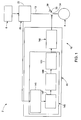
FIG. 1 is a block diagram illustrating an over current protection system in accordance with an example embodiment; -
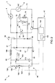
FIG. 2 is a schematic diagram illustrating the over current protection system ofFIG. 1 ; and -
FIG. 3 is a flow chart illustrating a method of protecting an electrical load from an over current condition in accordance with an example embodiment. - The detailed description explains embodiments of the invention, together with advantages and features, by way of example with reference to the drawings.
- With reference to
FIG. 1 , a motor controller system in accordance with an example embodiment is indicated generally at 2.Motor controller system 2 includes anelectric motor 4 electrically coupled to apower source 6 and an overcurrent protection system 10 through anelectric circuit 13. In the example embodiment shown, overcurrent protection system 10 includes acurrent sensing member 20 that detects a rate of change (di/dt) of current passing throughelectric circuit 13. In accordance with one aspect of the example embodiment,current sensing member 20 takes the form of aHall Effect Sensor 22. However, it should be understood that other devices capable of detecting a rate of change of electrical current could also be employed. As will be detailed more fully below, overcurrent protection system 10 is also shown to include a micro electro-mechanical switch (MEMS)device 30 that takes the form of aMEMS die 33 having at least oneswitch 34 and acontroller 40. - As best shown in
FIG. 2 ,MEMS device 30 is connected across a center point (not separately labeled) of abalanced diode bridge 50 formed by a plurality of corner diodes 55-58. In accordance with an example embodiment,MEMS device 30 is closely coupled to corner diodes 55-58. The term "closely coupled" should be understood to mean thatMEMS device 30 is coupled to corner diodes 55-58 with as small of a loop area as possible so as to limit voltage created by stray inductance associated with the loop area is limited to no more than about 1 V. In accordance with one aspect of the example embodiment, the term closely coupled should be interpreted to mean thatMEMS device 30 is coupled to corner diodes 55-58 with a loop area in which voltage created by stray inductance is limited to less than about 1 V. The loop area is defined as the area betweenMEMS device 30 andbalanced diode bridge 50. In accordance with one aspect of the example embodiment, an inductive voltage drop acrossMEMS device 30 during a switching event is controlled by maintaining a small loop inductance betweenMEMS die 33 and corner diodes 55-58. The inductive voltage acrossMEMS device 30 during switching is determined by three factors: the length of the loop area which establishes the level of stray inductance; MEMS switch current that is between about 1 A and about 10 A per parallel leg; and MEMS switching time which is about 1 µsec. - In still further accordance with the example embodiment, the desired loop area can be achieved by, for example, mounting
MEMS device 30 on one side of a circuit board (not separately labeled) and corner diodes 55-58 on another side of the circuit board, directly oppositeMEMS device 30. In accordance with another example, corner diodes 55-58 could be integrally formed within MEMS die 33. In any event, it should be understood that the particular arrangement ofMEMS device 30 and corner diodes 55-58 can vary so long as the loop area, and, by extension, inductance, is maintained as small as possible. It should also be understood that the number of MEMS devices as well as the number of switches carried by a particular MEMS die could vary. While embodiments of the invention are described employing corner diodes 55-58, it will be appreciated that the term "corner" is not limited to a physical location of the diodes, but is rather directed to a placement of the diodes relative to theMEMS die 33. - As discussed above, corner diodes 55-58 are arranged in
balanced diode bridge 50 so as to provide a low impedance path for load current passing throughMEMS device 30. As such, corner diodes 55-58 are arranged so as to limit inductance which, in turn, limits voltage changes over time, i.e., voltage spikes acrossMEMS device 30. In the example embodiment shown,balanced diode bridge 50 includes afirst branch 61 and asecond branch 62. As used herein, the term "balanced diode bridge" describes a diode bridge that is configured such that voltage drops across both the first andsecond branches branch first branch 61,diode 55 anddiode 56 are coupled together to form a first series circuit (not separately labeled). - In a similar fashion,
second branch 61 includesdiode 57 anddiode 58 operatively coupled together to form a second series circuit (also not separately labeled). Overcurrent protection system 10 is also shown connected to avoltage snubber 70 that is connected in parallel relative toMEMS device 30 as well aspower source 6 andelectric motor 4. Voltage snubber 70 limits voltage overshoot during fast contact separation of each ofMEMS switch 34.Voltage snubber 70 is shown in the form of a metal-oxide varistor (MOV) 74.MOV 74 is shown coupled to asnubber capacitor 76 that is connected in series with asnubber resistor 78.Snubber capacitor 76 andsnubber resistor 78 are electrically connected in parallel toMOV 74. - In further accordance with the example embodiment, over current protection system is shown to include a single Hybrid Arcless Limiting Technology (HALT)/Pulse Activated Turn On (PATO)
circuit 90. HALT/PATO circuit 90 includes afirst branch 93 that is electrically connected tofirst branch 61 ofbalanced diode bridge 50 and asecond branch 95 that is electrically connected tosecond branch 62 ofbalanced diode bridge 50. HALT/PATO circuit 90 includes aHALT circuit portion 104 and aPATO circuit portion 106 electrically connected between first andsecond branches common inductor 108. -
HALT circuit portion 104 is connected in parallel toPATO circuit portion 106.HALT circuit portion 104 includes aHALT switch 112 shown in the form of aswitching device 114.Switching device 114 is connected in series with aHALT capacitor 115.PATO circuit portion 106 includes apulse switch 120 shown in the form of aswitching device 122 connected in series with apulse capacitor 123 and apulse diode 124.Inductor 108 is connected in series to HALT andPATO circuit portions first branch 93. As will become more fully evident below,HALT switch 112 is selectively closed to openMEMS die 33, andpulse switch 120 is selectively closed to closeMEMS die 33. That is,HALT switch 112 is closed to electrically powerHALT circuit portion 104 to openMEMS device 30, andpulse switch 120 is closed to electrically powerPATO circuit portion 106 to closeMEMS device 30. The closing ofMEMS device 30 completeselectric circuit 13 allowing electrical current to flow frompower source 6 toelectric motor 4. Conversely, openingMEMS device 30 disrupts the flow of electrical current betweenpower source 6 andelectric motor 4. - In still further accordance with the example embodiment,
controller 40 includes a shortcircuit detection portion 140 electrically coupled to amotor drive portion 142.Motor drive portion 142 selectively signalsPATO circuit portion 106 andHALT circuit portion 104 to close andopen MEMS device 30 in response to a motor start signal and a motor stop signal. In addition,motor drive portion 142 will signalHALT circuit portion 104 to openMEMS device 30 in the event of an over current condition signaled by shortcircuit detection portion 140. Shortcircuit detection portion 140 includes an operational amplifier (Op Amp) 145 electrically coupled to arectifier 147, acomparator 149 and amicro-controller 151.Op Amp 145 generates a rate of change (di/dt) signal based in inputs fromcurrent sensing member 20. The rate of change signal is passed torectifier 147.Rectifier 147 converts the rate of change signal into a unipolar rate of change signal that is passed tocomparator 149.Comparator 149 compares the unipolar rate of change signal with a predetermined threshold value. If the unipolar rate of change signal is above the predetermined threshold value, an output signal is passed tomotor drive portion 142 viamicro-controller 151 to activateHALT circuit portion 104 andopen MEMS device 30 cutting off the flow of electrical current inelectric circuit 13 to protectelectric motor 4 from over or short circuit current. - Reference will now be made to
FIG. 3 in describing amethod 200 of protectingelectric motor 4 from an over or short circuit condition. Initially,controller 40 receives a motor start signal/request as indicated inblock 220. Upon receipt of the start signal,motor drive portion 142signals pulse switch 120 to close and send a PATO pulse throughPATO circuit portion 106 to closeMEMS device 30 as indicated inblock 222. At this point, shortcircuit detection portion 140 begins to monitor the rate of change of the electrical current inblock 223 and determine, inblock 224, whether a short circuit condition exists. If the detected rate of change exceeds the predetermined threshold value, motor starting is aborted, the signal is cut off topulse switch 120 and a signal is sent to HALTswitch 112 to openMEMS device 30 as indicated inblock 226. Of course it should be understood that the predetermined threshold value for motor starting may be different than the predetermined threshold value for a running condition to account for any differences associated with motor starting current. - If no short circuit is detected upon start up, a second PATO pulse is issued as indicated in
block 230 andMEMS device 30 is turned on or closes to connect electric motor is connected topower source 6 as indicated inblock 232. At this point, shortcircuit detection system 140 monitors for the rate of change of current as indicated inblock 234 and determine, as indicated inblock 236, whether a post start short circuit condition exists. If a short circuit is detected in block 236 a HALT pulse is dent throughHALT circuit 104 to signalMEMS device 30 to open MEMS switch to cease motor operation as indicted inblock 246, otherwiseelectric motor 4 continues normal operation as indicated inblock 250 - At this point, it should be understood that the example embodiments provide a system to monitor for over current conditions to protect an electrical load such as an electric motor. In contrast to prior art arrangements that monitor for changes in an amplitude of electric current, the example embodiments monitor an electrical current rate of change. In this manner, the example embodiments provide a faster response time that reduces the electric motor's risk of exposure to short circuit currents. In addition, the use of a MEMS device to cut off current flow provides a response time that is nearly an order of magnitude faster than existing systems. More specifically, the use of MEMS devices reduces circuit reaction time to no more than about 16 µsecs.
- While the invention has been described in detail in connection with only a limited number of embodiments, it should be readily understood that the invention is not limited to such disclosed embodiments. Rather, the invention can be modified to incorporate any number of variations, alterations, substitutions or equivalent arrangements not heretofore described, but which are commensurate with the scope of the invention as defined in the appended claims. Additionally, while various embodiments of the invention have been described, it is to be understood that aspects of the invention may include only some of the described embodiments. Accordingly, the invention is not to be seen as limited by the foregoing description, but is only limited by the scope of the appended claims.
Claims (12)
- An over current protection system (10) comprising:a current sensing member (20) configured and disposed to output an electrical rate of change signal indicative of a rate of change of an electrical current being in excess of a predetermined value;at least one micro electro-mechanical switch (MEMS) device (30) operatively connected to the current sensing member (20); anda controller (40) electrically coupled to each of the current sensing member (20) and the at least one MEMS device (30), the controller (40) being configured and disposed to open the at least one MEMS device (30) in response to the electrical rate of change signal from the current sensing member (20).
- The over current protection system (10) according to claim 1, further comprising: a diode bridge (50) closely coupled to the at least one MEMS device (30).
- The over current protection system (10) according to claim 2, wherein the diode bridge (50) is coupled to the at least one MEMS device (30) through a loop area in which stray inductance is limited to between no more than about 1 V.
- The over current protection system (10) according to claim 2, wherein the diode bridge (50) is coupled to the at least one MEMS device (30) through a loop area in which stray inductance is limited to less than about 1 V.
- The over current protection system (10) according to claim 2, 3 or 4, further comprising: a Pulse Assist Turn-On (PATO) circuit (90) electrically coupled to the diode bridge (50).
- The over current protection system (10) according to claim 2, 3, 4 or 5, further comprising: a Hybrid Arcless Limiting Technology (HALT) circuit (90) electrically coupled to the diode bridge (50).
- The over-current protection system (10) according to any one of claims 1 to 6, wherein the controller (40) includes at least one micro-controller (151), and at least one of an operational amplifier (145), a rectifier (147), and a comparator (149), the micro-controller (151) being operatively coupled to the at least one operational amplifier (145), rectifier (147) and comparator (149).
- A motor controller system comprising:an electric motor (4) coupled to an electric circuit; andan over current protection system (10) according to any one of claims 1 to 7, wherein:the at least one micro electro-mechanical switch (MEMS) device (30) is arranged in the electric circuit and operatively connected to the current sensing member (20) and the electric motor (4); andthe controller (40) comprises a motor controller electrically coupled to each of the current sensing member (20) and the at least one MEMS device (30), the motor controller being configured and disposed to open the at least one MEMS device (30) in response to the electrical rate of change signal.
- A method of protecting an electrical load from an over current condition, the method comprising:issuing a Pulse Assist Turn On (PATO) pulse through a PATO circuit (90) to close a micro electro-mechanical switch (MEMS) device (30) electrically coupled to the load through an electric circuit;sensing an electrical current passing through the electric circuit toward the electrical load;monitoring for a rate of change of the electrical current in the electric circuit;determining that the rate of change of the electrical current is in excess of a predetermined value; andissuing a signal to open the MEMS device (30) upon detecting that the rate of change of the electrical current is in excess of the predetermined value.
- The method of claim 9, further comprising:passing the electrical current to the electrical load if the rate of change of the electrical current is below the predetermined value; andmonitoring the electrical current.
- The method of claim 9 or claim 10, further comprising: issuing a Hybrid Arcless Limiting Technology (HALT) signal to open the MEMS device (30) if the rate of change of the electrical current exceeds the predetermined value.
- The method of claim 9, 10 or 11, wherein the MEMS device (30) is configured to open after no more than 16 µsec of detecting the rate of change of the electrical current in excess of the predetermined value.
Applications Claiming Priority (1)
| Application Number | Priority Date | Filing Date | Title |
|---|---|---|---|
| US13/190,065 US20130027817A1 (en) | 2011-07-25 | 2011-07-25 | Micro electro-mechanical switch (mems) based over current motor protection system |
Publications (3)
| Publication Number | Publication Date |
|---|---|
| EP2568559A2 true EP2568559A2 (en) | 2013-03-13 |
| EP2568559A3 EP2568559A3 (en) | 2013-03-20 |
| EP2568559B1 EP2568559B1 (en) | 2014-09-10 |
Family
ID=47146152
Family Applications (1)
| Application Number | Title | Priority Date | Filing Date |
|---|---|---|---|
| EP12176972.3A Active EP2568559B1 (en) | 2011-07-25 | 2012-07-18 | Micro electro-mechanical switch (MEMS) based over current motor protection system |
Country Status (4)
| Country | Link |
|---|---|
| US (1) | US20130027817A1 (en) |
| EP (1) | EP2568559B1 (en) |
| JP (1) | JP2013027303A (en) |
| CN (1) | CN102904214B (en) |
Cited By (1)
| Publication number | Priority date | Publication date | Assignee | Title |
|---|---|---|---|---|
| US20210074489A1 (en) * | 2019-09-09 | 2021-03-11 | Andreas Stihl Ag & Co. Kg | Method for operating an electrical treatment device and electrical treatment device |
Families Citing this family (6)
| Publication number | Priority date | Publication date | Assignee | Title |
|---|---|---|---|---|
| KR101343447B1 (en) * | 2012-06-11 | 2013-12-20 | 엘에스산전 주식회사 | Motor starter system and operation method of the same |
| US9001476B2 (en) * | 2013-03-15 | 2015-04-07 | Rockwell Automation Technologies, Inc. | Multimotor variable frequency overload |
| US10211622B2 (en) * | 2016-06-29 | 2019-02-19 | General Electric Company | System and method for fault interruption with MEMS switches |
| CN109586242B (en) * | 2017-09-29 | 2020-03-10 | 昆山国显光电有限公司 | Circuit protection method, protection circuit and circuit protection device |
| IT201900013065A1 (en) * | 2019-07-26 | 2021-01-26 | Eldor Corp Spa | Power supply system with protection against current variations |
| DE102024210306A1 (en) | 2024-10-25 | 2026-04-30 | Robert Bosch Gesellschaft mit beschränkter Haftung | Microelectromechanical switch with load-dependent switching control |
Family Cites Families (11)
| Publication number | Priority date | Publication date | Assignee | Title |
|---|---|---|---|---|
| DE4009184A1 (en) * | 1990-03-22 | 1991-09-26 | Heidelberger Druckmasch Ag | METHOD FOR SUPPRESSING CURRENT PEAKS DURING COMMUNICATION OF A BRUSHLESS DC MOTOR |
| US5973896A (en) * | 1995-05-26 | 1999-10-26 | David C. Nemir | Shock and arc protection device for an electrical distribution system |
| US5943223A (en) * | 1997-10-15 | 1999-08-24 | Reliance Electric Industrial Company | Electric switches for reducing on-state power loss |
| US7253615B2 (en) * | 2004-05-05 | 2007-08-07 | General Electric Company | Microelectromechanical system sensor and method for using |
| US7876538B2 (en) * | 2005-12-20 | 2011-01-25 | General Electric Company | Micro-electromechanical system based arc-less switching with circuitry for absorbing electrical energy during a fault condition |
| US7332835B1 (en) * | 2006-11-28 | 2008-02-19 | General Electric Company | Micro-electromechanical system based switching module serially stackable with other such modules to meet a voltage rating |
| US7643256B2 (en) * | 2006-12-06 | 2010-01-05 | General Electric Company | Electromechanical switching circuitry in parallel with solid state switching circuitry selectively switchable to carry a load appropriate to such circuitry |
| US7542250B2 (en) * | 2007-01-10 | 2009-06-02 | General Electric Company | Micro-electromechanical system based electric motor starter |
| US7719812B2 (en) * | 2007-05-15 | 2010-05-18 | Astec International Limited | Power converters with rate of change monitoring for fault prediction and/or detection |
| US8358488B2 (en) * | 2007-06-15 | 2013-01-22 | General Electric Company | Micro-electromechanical system based switching |
| US8054589B2 (en) * | 2009-12-16 | 2011-11-08 | General Electric Company | Switch structure and associated circuit |
-
2011
- 2011-07-25 US US13/190,065 patent/US20130027817A1/en not_active Abandoned
-
2012
- 2012-07-18 EP EP12176972.3A patent/EP2568559B1/en active Active
- 2012-07-18 JP JP2012159146A patent/JP2013027303A/en active Pending
- 2012-07-25 CN CN201210258994.8A patent/CN102904214B/en active Active
Non-Patent Citations (1)
| Title |
|---|
| None |
Cited By (2)
| Publication number | Priority date | Publication date | Assignee | Title |
|---|---|---|---|---|
| US20210074489A1 (en) * | 2019-09-09 | 2021-03-11 | Andreas Stihl Ag & Co. Kg | Method for operating an electrical treatment device and electrical treatment device |
| US11651911B2 (en) * | 2019-09-09 | 2023-05-16 | Andreas Stihl Ag & Co. Kg | Method for operating an electrical treatment device and electrical treatment device |
Also Published As
| Publication number | Publication date |
|---|---|
| US20130027817A1 (en) | 2013-01-31 |
| CN102904214A (en) | 2013-01-30 |
| EP2568559A3 (en) | 2013-03-20 |
| EP2568559B1 (en) | 2014-09-10 |
| JP2013027303A (en) | 2013-02-04 |
| CN102904214B (en) | 2016-12-21 |
Similar Documents
| Publication | Publication Date | Title |
|---|---|---|
| EP2568559B1 (en) | Micro electro-mechanical switch (MEMS) based over current motor protection system | |
| CN110171470B (en) | Motor driving circuit system | |
| EP3404790B1 (en) | Power supply control device | |
| CN109417347B (en) | System and method for intelligent disconnection in adjustable speed drives | |
| US5774319A (en) | Energy validation arrangement for a self-powered circuit interrupter | |
| CN102204051B (en) | Method and device for activating monitoring by a jamming protection function in an electrical closing system | |
| EP2587601A2 (en) | Active current surge limiters with disturbance sensor and multistage current limiting | |
| DK2149890T3 (en) | Enkeltspoleaktuator for low and medium voltage applications | |
| US20140188359A1 (en) | Electric brake assist system for vehicle use | |
| WO1997018611A9 (en) | Energy validation arrangement for a self-powered circuit interrupter | |
| EP2584366B1 (en) | A relay with an intermediate alert mechanism | |
| EP3147923B1 (en) | Electromagnet drive device | |
| CN104764174B (en) | Conditioner | |
| KR20170070889A (en) | Device for preventing a reverse current of the DC-DC converter of vehicle and method thereof | |
| EP2573891B1 (en) | Overvoltage protection using a link current sensor | |
| JP2022147918A (en) | On-vehicle protector | |
| US6160955A (en) | Control circuits of an apparatus for physical exercises | |
| US10291159B2 (en) | Control system, controller, and control method for wound induction machine | |
| US8884557B2 (en) | Disconnection from mains using switches for power tools | |
| EP3665489B1 (en) | Fault tolerant solenoid actuation and monitoring | |
| US20250364802A1 (en) | End effector with integrated feedback protection device, and method | |
| US10063165B2 (en) | Method and apparatus for the detection of the position of an operating switch for starting an electric motor | |
| US20110222198A1 (en) | Alternating current overload protection apparatus and method | |
| CN101299373A (en) | Method of operating circuit arrangement, circuit arrangement and magnetic valve and electronic braking system | |
| CN115088185A (en) | Method for diagnosing fault of power input circuit and system thereof |
Legal Events
| Date | Code | Title | Description |
|---|---|---|---|
| PUAL | Search report despatched |
Free format text: ORIGINAL CODE: 0009013 |
|
| PUAI | Public reference made under article 153(3) epc to a published international application that has entered the european phase |
Free format text: ORIGINAL CODE: 0009012 |
|
| AK | Designated contracting states |
Kind code of ref document: A2 Designated state(s): AL AT BE BG CH CY CZ DE DK EE ES FI FR GB GR HR HU IE IS IT LI LT LU LV MC MK MT NL NO PL PT RO RS SE SI SK SM TR |
|
| AX | Request for extension of the european patent |
Extension state: BA ME |
|
| AK | Designated contracting states |
Kind code of ref document: A3 Designated state(s): AL AT BE BG CH CY CZ DE DK EE ES FI FR GB GR HR HU IE IS IT LI LT LU LV MC MK MT NL NO PL PT RO RS SE SI SK SM TR |
|
| AX | Request for extension of the european patent |
Extension state: BA ME |
|
| RIC1 | Information provided on ipc code assigned before grant |
Ipc: H02H 3/44 20060101AFI20130211BHEP Ipc: H01H 59/00 20060101ALI20130211BHEP |
|
| 17P | Request for examination filed |
Effective date: 20130920 |
|
| RBV | Designated contracting states (corrected) |
Designated state(s): AL AT BE BG CH CY CZ DE DK EE ES FI FR GB GR HR HU IE IS IT LI LT LU LV MC MK MT NL NO PL PT RO RS SE SI SK SM TR |
|
| GRAP | Despatch of communication of intention to grant a patent |
Free format text: ORIGINAL CODE: EPIDOSNIGR1 |
|
| INTG | Intention to grant announced |
Effective date: 20140314 |
|
| GRAS | Grant fee paid |
Free format text: ORIGINAL CODE: EPIDOSNIGR3 |
|
| GRAA | (expected) grant |
Free format text: ORIGINAL CODE: 0009210 |
|
| AK | Designated contracting states |
Kind code of ref document: B1 Designated state(s): AL AT BE BG CH CY CZ DE DK EE ES FI FR GB GR HR HU IE IS IT LI LT LU LV MC MK MT NL NO PL PT RO RS SE SI SK SM TR |
|
| REG | Reference to a national code |
Ref country code: GB Ref legal event code: FG4D |
|
| REG | Reference to a national code |
Ref country code: CH Ref legal event code: EP |
|
| REG | Reference to a national code |
Ref country code: IE Ref legal event code: FG4D |
|
| REG | Reference to a national code |
Ref country code: AT Ref legal event code: REF Ref document number: 687116 Country of ref document: AT Kind code of ref document: T Effective date: 20141015 |
|
| REG | Reference to a national code |
Ref country code: DE Ref legal event code: R096 Ref document number: 602012003038 Country of ref document: DE Effective date: 20141023 |
|
| PG25 | Lapsed in a contracting state [announced via postgrant information from national office to epo] |
Ref country code: NO Free format text: LAPSE BECAUSE OF FAILURE TO SUBMIT A TRANSLATION OF THE DESCRIPTION OR TO PAY THE FEE WITHIN THE PRESCRIBED TIME-LIMIT Effective date: 20141210 Ref country code: FI Free format text: LAPSE BECAUSE OF FAILURE TO SUBMIT A TRANSLATION OF THE DESCRIPTION OR TO PAY THE FEE WITHIN THE PRESCRIBED TIME-LIMIT Effective date: 20140910 Ref country code: SE Free format text: LAPSE BECAUSE OF FAILURE TO SUBMIT A TRANSLATION OF THE DESCRIPTION OR TO PAY THE FEE WITHIN THE PRESCRIBED TIME-LIMIT Effective date: 20140910 Ref country code: GR Free format text: LAPSE BECAUSE OF FAILURE TO SUBMIT A TRANSLATION OF THE DESCRIPTION OR TO PAY THE FEE WITHIN THE PRESCRIBED TIME-LIMIT Effective date: 20141211 Ref country code: ES Free format text: LAPSE BECAUSE OF FAILURE TO SUBMIT A TRANSLATION OF THE DESCRIPTION OR TO PAY THE FEE WITHIN THE PRESCRIBED TIME-LIMIT Effective date: 20140910 Ref country code: LT Free format text: LAPSE BECAUSE OF FAILURE TO SUBMIT A TRANSLATION OF THE DESCRIPTION OR TO PAY THE FEE WITHIN THE PRESCRIBED TIME-LIMIT Effective date: 20140910 |
|
| REG | Reference to a national code |
Ref country code: NL Ref legal event code: VDEP Effective date: 20140910 |
|
| REG | Reference to a national code |
Ref country code: LT Ref legal event code: MG4D |
|
| PG25 | Lapsed in a contracting state [announced via postgrant information from national office to epo] |
Ref country code: LV Free format text: LAPSE BECAUSE OF FAILURE TO SUBMIT A TRANSLATION OF THE DESCRIPTION OR TO PAY THE FEE WITHIN THE PRESCRIBED TIME-LIMIT Effective date: 20140910 Ref country code: CY Free format text: LAPSE BECAUSE OF FAILURE TO SUBMIT A TRANSLATION OF THE DESCRIPTION OR TO PAY THE FEE WITHIN THE PRESCRIBED TIME-LIMIT Effective date: 20140910 Ref country code: HR Free format text: LAPSE BECAUSE OF FAILURE TO SUBMIT A TRANSLATION OF THE DESCRIPTION OR TO PAY THE FEE WITHIN THE PRESCRIBED TIME-LIMIT Effective date: 20140910 Ref country code: RS Free format text: LAPSE BECAUSE OF FAILURE TO SUBMIT A TRANSLATION OF THE DESCRIPTION OR TO PAY THE FEE WITHIN THE PRESCRIBED TIME-LIMIT Effective date: 20140910 |
|
| REG | Reference to a national code |
Ref country code: AT Ref legal event code: MK05 Ref document number: 687116 Country of ref document: AT Kind code of ref document: T Effective date: 20140910 |
|
| PG25 | Lapsed in a contracting state [announced via postgrant information from national office to epo] |
Ref country code: NL Free format text: LAPSE BECAUSE OF FAILURE TO SUBMIT A TRANSLATION OF THE DESCRIPTION OR TO PAY THE FEE WITHIN THE PRESCRIBED TIME-LIMIT Effective date: 20140910 |
|
| PG25 | Lapsed in a contracting state [announced via postgrant information from national office to epo] |
Ref country code: CZ Free format text: LAPSE BECAUSE OF FAILURE TO SUBMIT A TRANSLATION OF THE DESCRIPTION OR TO PAY THE FEE WITHIN THE PRESCRIBED TIME-LIMIT Effective date: 20140910 Ref country code: RO Free format text: LAPSE BECAUSE OF FAILURE TO SUBMIT A TRANSLATION OF THE DESCRIPTION OR TO PAY THE FEE WITHIN THE PRESCRIBED TIME-LIMIT Effective date: 20140910 Ref country code: PT Free format text: LAPSE BECAUSE OF FAILURE TO SUBMIT A TRANSLATION OF THE DESCRIPTION OR TO PAY THE FEE WITHIN THE PRESCRIBED TIME-LIMIT Effective date: 20150112 Ref country code: IS Free format text: LAPSE BECAUSE OF FAILURE TO SUBMIT A TRANSLATION OF THE DESCRIPTION OR TO PAY THE FEE WITHIN THE PRESCRIBED TIME-LIMIT Effective date: 20150110 Ref country code: SK Free format text: LAPSE BECAUSE OF FAILURE TO SUBMIT A TRANSLATION OF THE DESCRIPTION OR TO PAY THE FEE WITHIN THE PRESCRIBED TIME-LIMIT Effective date: 20140910 Ref country code: EE Free format text: LAPSE BECAUSE OF FAILURE TO SUBMIT A TRANSLATION OF THE DESCRIPTION OR TO PAY THE FEE WITHIN THE PRESCRIBED TIME-LIMIT Effective date: 20140910 |
|
| PG25 | Lapsed in a contracting state [announced via postgrant information from national office to epo] |
Ref country code: PL Free format text: LAPSE BECAUSE OF FAILURE TO SUBMIT A TRANSLATION OF THE DESCRIPTION OR TO PAY THE FEE WITHIN THE PRESCRIBED TIME-LIMIT Effective date: 20140910 Ref country code: AT Free format text: LAPSE BECAUSE OF FAILURE TO SUBMIT A TRANSLATION OF THE DESCRIPTION OR TO PAY THE FEE WITHIN THE PRESCRIBED TIME-LIMIT Effective date: 20140910 |
|
| REG | Reference to a national code |
Ref country code: DE Ref legal event code: R097 Ref document number: 602012003038 Country of ref document: DE |
|
| PLBE | No opposition filed within time limit |
Free format text: ORIGINAL CODE: 0009261 |
|
| STAA | Information on the status of an ep patent application or granted ep patent |
Free format text: STATUS: NO OPPOSITION FILED WITHIN TIME LIMIT |
|
| PG25 | Lapsed in a contracting state [announced via postgrant information from national office to epo] |
Ref country code: DK Free format text: LAPSE BECAUSE OF FAILURE TO SUBMIT A TRANSLATION OF THE DESCRIPTION OR TO PAY THE FEE WITHIN THE PRESCRIBED TIME-LIMIT Effective date: 20140910 |
|
| 26N | No opposition filed |
Effective date: 20150611 |
|
| PG25 | Lapsed in a contracting state [announced via postgrant information from national office to epo] |
Ref country code: IT Free format text: LAPSE BECAUSE OF FAILURE TO SUBMIT A TRANSLATION OF THE DESCRIPTION OR TO PAY THE FEE WITHIN THE PRESCRIBED TIME-LIMIT Effective date: 20140910 |
|
| PG25 | Lapsed in a contracting state [announced via postgrant information from national office to epo] |
Ref country code: SI Free format text: LAPSE BECAUSE OF FAILURE TO SUBMIT A TRANSLATION OF THE DESCRIPTION OR TO PAY THE FEE WITHIN THE PRESCRIBED TIME-LIMIT Effective date: 20140910 |
|
| PG25 | Lapsed in a contracting state [announced via postgrant information from national office to epo] |
Ref country code: MC Free format text: LAPSE BECAUSE OF FAILURE TO SUBMIT A TRANSLATION OF THE DESCRIPTION OR TO PAY THE FEE WITHIN THE PRESCRIBED TIME-LIMIT Effective date: 20140910 |
|
| REG | Reference to a national code |
Ref country code: CH Ref legal event code: PL |
|
| PG25 | Lapsed in a contracting state [announced via postgrant information from national office to epo] |
Ref country code: LU Free format text: LAPSE BECAUSE OF FAILURE TO SUBMIT A TRANSLATION OF THE DESCRIPTION OR TO PAY THE FEE WITHIN THE PRESCRIBED TIME-LIMIT Effective date: 20150718 |
|
| REG | Reference to a national code |
Ref country code: IE Ref legal event code: MM4A |
|
| PG25 | Lapsed in a contracting state [announced via postgrant information from national office to epo] |
Ref country code: LI Free format text: LAPSE BECAUSE OF NON-PAYMENT OF DUE FEES Effective date: 20150731 Ref country code: CH Free format text: LAPSE BECAUSE OF NON-PAYMENT OF DUE FEES Effective date: 20150731 |
|
| REG | Reference to a national code |
Ref country code: FR Ref legal event code: ST Effective date: 20160331 |
|
| PG25 | Lapsed in a contracting state [announced via postgrant information from national office to epo] |
Ref country code: FR Free format text: LAPSE BECAUSE OF NON-PAYMENT OF DUE FEES Effective date: 20150731 |
|
| PG25 | Lapsed in a contracting state [announced via postgrant information from national office to epo] |
Ref country code: BE Free format text: LAPSE BECAUSE OF FAILURE TO SUBMIT A TRANSLATION OF THE DESCRIPTION OR TO PAY THE FEE WITHIN THE PRESCRIBED TIME-LIMIT Effective date: 20140910 Ref country code: IE Free format text: LAPSE BECAUSE OF NON-PAYMENT OF DUE FEES Effective date: 20150718 |
|
| GBPC | Gb: european patent ceased through non-payment of renewal fee |
Effective date: 20160718 |
|
| PG25 | Lapsed in a contracting state [announced via postgrant information from national office to epo] |
Ref country code: MT Free format text: LAPSE BECAUSE OF FAILURE TO SUBMIT A TRANSLATION OF THE DESCRIPTION OR TO PAY THE FEE WITHIN THE PRESCRIBED TIME-LIMIT Effective date: 20140910 |
|
| PG25 | Lapsed in a contracting state [announced via postgrant information from national office to epo] |
Ref country code: HU Free format text: LAPSE BECAUSE OF FAILURE TO SUBMIT A TRANSLATION OF THE DESCRIPTION OR TO PAY THE FEE WITHIN THE PRESCRIBED TIME-LIMIT; INVALID AB INITIO Effective date: 20120718 Ref country code: GB Free format text: LAPSE BECAUSE OF NON-PAYMENT OF DUE FEES Effective date: 20160718 Ref country code: BG Free format text: LAPSE BECAUSE OF FAILURE TO SUBMIT A TRANSLATION OF THE DESCRIPTION OR TO PAY THE FEE WITHIN THE PRESCRIBED TIME-LIMIT Effective date: 20140910 Ref country code: SM Free format text: LAPSE BECAUSE OF FAILURE TO SUBMIT A TRANSLATION OF THE DESCRIPTION OR TO PAY THE FEE WITHIN THE PRESCRIBED TIME-LIMIT Effective date: 20140910 |
|
| PG25 | Lapsed in a contracting state [announced via postgrant information from national office to epo] |
Ref country code: TR Free format text: LAPSE BECAUSE OF FAILURE TO SUBMIT A TRANSLATION OF THE DESCRIPTION OR TO PAY THE FEE WITHIN THE PRESCRIBED TIME-LIMIT Effective date: 20140910 |
|
| PG25 | Lapsed in a contracting state [announced via postgrant information from national office to epo] |
Ref country code: MK Free format text: LAPSE BECAUSE OF FAILURE TO SUBMIT A TRANSLATION OF THE DESCRIPTION OR TO PAY THE FEE WITHIN THE PRESCRIBED TIME-LIMIT Effective date: 20140910 |
|
| PG25 | Lapsed in a contracting state [announced via postgrant information from national office to epo] |
Ref country code: AL Free format text: LAPSE BECAUSE OF FAILURE TO SUBMIT A TRANSLATION OF THE DESCRIPTION OR TO PAY THE FEE WITHIN THE PRESCRIBED TIME-LIMIT Effective date: 20140910 |
|
| REG | Reference to a national code |
Ref country code: DE Ref legal event code: R081 Ref document number: 602012003038 Country of ref document: DE Owner name: ABB SCHWEIZ AG, CH Free format text: FORMER OWNER: GENERAL ELECTRIC CO., SCHENECTADY, N.Y., US |
|
| REG | Reference to a national code |
Ref country code: DE Ref legal event code: R082 Ref document number: 602012003038 Country of ref document: DE Representative=s name: ZIMMERMANN & PARTNER PATENTANWAELTE MBB, DE |
|
| PGFP | Annual fee paid to national office [announced via postgrant information from national office to epo] |
Ref country code: DE Payment date: 20250722 Year of fee payment: 14 |