EP2568475A1 - Magnet and method for designing a magnet - Google Patents
Magnet and method for designing a magnet Download PDFInfo
- Publication number
- EP2568475A1 EP2568475A1 EP11180836A EP11180836A EP2568475A1 EP 2568475 A1 EP2568475 A1 EP 2568475A1 EP 11180836 A EP11180836 A EP 11180836A EP 11180836 A EP11180836 A EP 11180836A EP 2568475 A1 EP2568475 A1 EP 2568475A1
- Authority
- EP
- European Patent Office
- Prior art keywords
- coils
- path
- region
- magnetic field
- magnet
- Prior art date
- Legal status (The legal status is an assumption and is not a legal conclusion. Google has not performed a legal analysis and makes no representation as to the accuracy of the status listed.)
- Withdrawn
Links
Images




Classifications
-
- G—PHYSICS
- G21—NUCLEAR PHYSICS; NUCLEAR ENGINEERING
- G21K—HANDLING OF PARTICLES OR IONISING RADIATION NOT OTHERWISE PROVIDED FOR; IRRADIATION DEVICES; GAMMA RAY OR X-RAY MICROSCOPES
- G21K1/00—Arrangements for handling particles or ionising radiation, e.g. focusing or moderating
- G21K1/08—Deviation, concentration or focusing of the beam by electric or magnetic means
- G21K1/093—Deviation, concentration or focusing of the beam by electric or magnetic means by magnetic means
-
- H—ELECTRICITY
- H01—ELECTRIC ELEMENTS
- H01F—MAGNETS; INDUCTANCES; TRANSFORMERS; SELECTION OF MATERIALS FOR THEIR MAGNETIC PROPERTIES
- H01F5/00—Coils
-
- H—ELECTRICITY
- H01—ELECTRIC ELEMENTS
- H01F—MAGNETS; INDUCTANCES; TRANSFORMERS; SELECTION OF MATERIALS FOR THEIR MAGNETIC PROPERTIES
- H01F6/00—Superconducting magnets; Superconducting coils
- H01F6/06—Coils, e.g. winding, insulating, terminating or casing arrangements therefor
-
- H—ELECTRICITY
- H05—ELECTRIC TECHNIQUES NOT OTHERWISE PROVIDED FOR
- H05H—PLASMA TECHNIQUE; PRODUCTION OF ACCELERATED ELECTRICALLY-CHARGED PARTICLES OR OF NEUTRONS; PRODUCTION OR ACCELERATION OF NEUTRAL MOLECULAR OR ATOMIC BEAMS
- H05H7/00—Details of devices of the types covered by groups H05H9/00, H05H11/00, H05H13/00
- H05H7/04—Magnet systems, e.g. undulators, wigglers; Energisation thereof
-
- H—ELECTRICITY
- H05—ELECTRIC TECHNIQUES NOT OTHERWISE PROVIDED FOR
- H05H—PLASMA TECHNIQUE; PRODUCTION OF ACCELERATED ELECTRICALLY-CHARGED PARTICLES OR OF NEUTRONS; PRODUCTION OR ACCELERATION OF NEUTRAL MOLECULAR OR ATOMIC BEAMS
- H05H7/00—Details of devices of the types covered by groups H05H9/00, H05H11/00, H05H13/00
- H05H7/04—Magnet systems, e.g. undulators, wigglers; Energisation thereof
- H05H2007/045—Magnet systems, e.g. undulators, wigglers; Energisation thereof for beam bending
Definitions
- the present invention relates generally to a magnet and more specifically to a magnet for guiding a beam of charged particles along a curved path.
- the invention also relates to a method for designing such a magnet and to a magnet obtained by the method.
- a beam guiding magnet for deflecting a particle beam is know from US 7812319 .
- This magnet comprises a first coil system having curved individual coils, disposed along the particle path, which are arranged in pairs in mirror symmetry to the path plane, the first coil system including two saddle-shaped first primary coils with side parts elongated in a direction of the particle path and end parts bent upward on a face end, at least two secondary coils, which are curved and surround an inner region, and at least two correction coils, which are curved and are located in the respective inner region of the secondary coils, and a second coil system having two second primary coils, which extend laterally of the particle path and are curved and which are located between the first primary coils and include a first and a second elongated side part, the first elongated side part is located close to the particle path and the second elongated side part is remote from the particle path.
- the design of these coils start from the assumption that the coil sections are rectangular. This leads to solutions that are far from optimal regarding performance criteria like the stored magnetic energy, the volume of conductive material, since less degrees of freedom are available for reaching the specific field distribution requirements in the beam region, and low field values outside the magnet.
- the first primary coils 201, 202 have end parts (401) bent upwards. These kinds of coils are more difficult to produce.
- the magnet is a superconducting magnet, which is the case in the embodiment described, it is more difficult to design the cryostat, and it is more difficult to design the means for supporting the forces resulting from the high currents.
- the present invention aims at providing a magnet and a method for designing a magnet that overcomes the above-discussed drawbacks of the prior art.
- manufacturability e.g. planar coils
- magnetic field and field gradient inside the magnet e.g. planar coils
- the invention relates to a magnet for guiding a beam of charged particles along a curved path in a path plane, comprising
- the magnet may comprise a beam guiding tube.
- the third and fourth coils may then have parts contiguous to said beam guiding tube. A branch of these coils leans against the beam guiding tube.
- the magnet may further comprise a fifth and sixth coil (gradient correction coils) disposed symmetrically with respect to said path plane, at said first and second distance of said path plane, inside said first and second coils, and adapted for producing a magnetic field in same direction perpendicular to said path plane along said path.
- a fifth and sixth coil gradient correction coils
- the magnet may also comprise a seventh and an eighth coil (shielding coils) disposed symmetrically with respect to said path plane, at a larger distance of said path plane than the first and second coil, and adapted for producing a magnetic field in opposite direction perpendicular to said path plane along said path.
- a seventh and an eighth coil shielding coils
- the magnet may also comprise a ninth and tenth coil (shielding correction coils) disposed along said path plane, at an outer side of said third and fourth coils respectively, and adapted for producing a magnetic field in opposite direction perpendicular to said path plane along said path.
- a ninth and tenth coil shielding correction coils
- the magnet may then also comprise further passive shielding material such as iron enclosing all the coils of the magnet.
- the shielding coils may then ensure a low magnetic field in the region of the shielding material, which will be in a field below saturation. Such a magnet will then produce a field depending linearly on the current in the coils.
- the coils may be adapted for producing a uniform magnetic field in a region enclosed between said first, second, third and fourth coils.
- the coils may also be adapted for producing a magnetic field having a uniform component and a component having a gradient along a radial direction of said curved path in said region.
- the coils are preferably planar coils.
- the coils may be a superposition of coils having a rectangular section and together approximating coils having a section with a curved portion. This makes the manufacturing of the coils easier, while keeping the advantage of the effect of coils having an outer shape with a curved portion.
- the coils axisymmetric symmetry along an azimuthal range.
- the invention relates to a method for designing a magnet for guiding a beam of charged particles along a path, comprising the steps of:
- said step of dividing the section further comprises dividing (IV) a low magnetic field region LFR wherein the magnetic field is lower than a limit, and enclosing said design region; and in that the set of constraints further comprises obtaining a magnetic field lower than said limit in said low magnetic field region LFR.
- the step of dividing the section may further comprise dividing in four areas: area 'A' above a plane parallel to the path plane, and located above the separation region; area 'C' a corresponding region below the path plane; areas 'B' and 'D' at the left and right of the separation region, between areas 'A' and 'C', and in that in each of these areas and for each line of cells parallel to the path plane in these areas, the sum of the current in each cell located on these lines is zero.
- the invention relates to a magnet obtainable by the method of the invention.
- orientation of the various coils discussed are qualified by the orientation of the magnetic field they produce at the curved path, in the center of the GFR region.
- This field may either be the central field of the coil, e.g. for the first and second coil, or the return field of the coil, e.g. for the third and fourth coil.
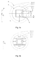
- Fig.1a is a schematic sectional view, in a plane orthogonal to the curved path, of a magnet according to the invention, where the different regions are represented.
- Fig.1b is a similar view, representing different areas.
- Fig.2 is a perspective view of a section of the coils of a magnet according to an embodiment of the invention.
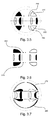
- Fig.3.1 to 3.13 are sectional views of various embodiments of magnets according to the invention, obtained by the method of the invention under different conditions.
- the magnet presents an axisymmetric symmetry along a bend angle of typically 90°. This magnet must be capable of bending beams of charged particles of different masses and of different energies. These requirements impose some specifications to the design that are discussed hereafter.
- the cross section of the bending magnet in the radial-axial plane (i.e. in a plane passing by the symmetry axis) is illustrated in Fig.1a .
- the particles travel on or around a particle path 10 in a path plane 20.
- the particle path 10 is curved around a symmetry axis 40 at a bend radius R b .
- the curved path 10 of the charged particles is orthogonal to the radial-axial plane of the figure. Starting from the center, the magnet is composed of:
- the two regions in which magnetic field specifications are imposed may be the GFR and the LFR.
- the field has to be such that the charged particles beam is bent but without refocusing it.
- a particle that is at the entry of the magnet with a speed normal to the entry section has to exit at the same radial position with a speed normal to the exit section.
- the value of the nominal field level and its radial nominal gradient depend of course on the particle beam that has to be bent, but it can be assumed that the gradient is proportional to the nominal field level.
- the maximal/nominal chosen values in the particular case of the current problem are presented below: Specifications for the good field region Nominal field B ng * 2.546 T Radial nominal gradient ⁇ B ng * -0.407 T / m Tolerated relative field error ⁇ B g 1.2 % Specifications for the low field region Maximal low field B l * 0.05 T
- the specifications for the low field region may be imposed first of all when cryocoolers are used for cooling down superconductive material but also to avoid any influence of ferromagnetic materials that may be located in the vicinity of the magnet.
- This constraint can be satisfied through passive shielding, using soft ferromagnetic parts disposed around the magnet or active shielding, using additional coils disposed around the magnet.
- a linear solution i.e. a solution producing a field proportional to the currents in the coils.
- Active shielding is the best and easiest way to obtain this linearity since it avoids the non-linearity due to the magnetic saturation in the soft ferromagnetic materials.
- a combination of an active and a passive shielding could also be satisfying if the active shielding is used to limit the magnetic field in ferromagnetic parts so as to keep them non-saturated.
- topology optimization is used to find new solutions that are not influenced by human prejudices.
- the design region (Zone III) is divided in cells. Each cell can be filled with conducting material or not, and the final scope of the optimization is to find the distribution of conducting materials that minimizes an objective function according to some constraints.
- the design variables are the proportions of materials in each cell.
- the model is in this particular embodiment restricted to a 2D axisymmetric geometry. This restriction prevents the analysis of the influence of the coils ends, however the optimization produces high performance coil designs.
- Each cell of the design region can only be filled with air or superconductor (NbTi in the present example).
- the currents flowing in a direction normal to a radial-axial plane, the algorithm will have two design variables for each cell:
- the superconducting quantity can be linked to the design variables ⁇ kp and ⁇ kn by the linear expression: ⁇ Cells k ⁇ 2 ⁇ r k ⁇ ⁇ kp + ⁇ kn ⁇ J max ⁇ S k with r k the radial position and S k the surface of cell k . If all the cells have the same surface, the expression can be reduced to: ⁇ Cells k r k ⁇ ⁇ kp + ⁇ kn
- Constraints The use of a linear optimization algorithm implies that all the constraints have to be linear with respect to the variables. To be as general as possible there are three types of constraints:
- Boundaries constraints are immediately converted to linear inequality constraints. The boundaries come from the tolerated maximal current density in each cell. Starting from (3), these constraints are formulated as follows: 0 ⁇ ⁇ kp ⁇ 1 0 ⁇ ⁇ kn ⁇ 1 for each cell k of the design region.
- Magnetic constraints To specify the magnetic constraints, the finite elements method is used to formulate the equations.
- publication « T. Labbé and B. Dehez, "Convexity-oriented mapping method for the topology optimization of electromagnetic devices composed of iron and coils," IEEE Transactions on Magnetics, vol. 46,n°. 5, pp. 1177 - 1185, Dec. 2009 .» we can write the relation : M ⁇ ⁇ u C ⁇ j with ⁇ the vector of the magnetic permeability, u the magnetic vector potential, j the vector of the local current densities, M and C the finite element matrices.
- equation (8) establishes a linear relation between the local current densities and the magnetic vector potential since the magnetic permeability can be supposed independent of the current level.
- Good field region constraints The distribution in the GFR has to be constrained with a specified tolerance. To reduce computer memory consumption, this constraint may be applied only to some control points, uniformly distributed in the GFR.
- the magnetic field are imposed with the tolerance ⁇ B g ; the constraints takes the form: ⁇ B zgk * ⁇ 1 - ⁇ B g 2 ⁇ b zk ⁇ B zgk * ⁇ 1 - ⁇ B g 2 - B zgk * ⁇ ⁇ B g 2 ⁇ b rk ⁇ B zgk * ⁇ ⁇ B g 2 with B zgk * the ideal values of the axial component of the magnetic field at the control point k obtained through equation (1).
- the low field constraint may be applied only to some control points for which a maximal magnetic field is imposed. These points are uniformly distributed on the inner limit of the LFR.
- the constraint takes the form: b rk 2 + b zk 2 ⁇ B l
- This formulation being not linear, it is transformed to the linear following conservative formulation: ⁇ - B l 2 ⁇ b rk ⁇ B l 2 - B l 2 ⁇ b zk ⁇ B l 2
- Coils constraints As discussed previously, a particular attention has to be taken to the coils: the coils should preferably be planar and their ends should preferably not pass in the GFR. To implement these constraints, the design region is divided in four areas, as shown on Fig.1b : Area 'A' is the area above a plane parallel to the path plane, and located above the separation region; Area 'C' is the corresponding region below the path plane; areas 'B' and 'D' are at the left and right of the separation region, between areas 'A' and 'C'. Areas 'B' and 'D' are at the inner and outer side respectively of the curve of the curved path of the particles.
- Fig.3.1 to 3.13 are radial-axial sectional views of various embodiments of magnets according to the invention, obtained by the method of the invention under different conditions and constraints explained hereunder.
- the section of the coils where the current flows outwards the radial-axial plane are represented in black
- the sections of the coils where the current flows in the opposite direction are represented in white.
- the current density is uniform, and may be obtained by a plurality of individual conductors wound in coils, as known in the art.
- First to tenth coils are designated by reference numbers 210 to 300, respectively.
- the granularity of the outer shape of the coils results from the cell discretization (i.e. the mesh size) used in the optimization.
- the applicant has observed that when performing the optimization with different mesh size, results showing very similar shapes are obtained. It will be understood that a finer granularity may be obtained at the cost of more computing time and memory, but that the in the actual implementation, these shapes may be smoothed without impairing the quality of the magnets.
- Fig.2 is a perspective view of a section of the coils 210, 220, 230, 240 of a magnet resulting from the application of the method of the invention with the cost function to be minimized being the volume of the electrical conductors needed for producing the required magnetic field
- the good field region (GFR) is a square area wherein the field is a dipolar field with a low radial gradient
- the coils are planar "race track" coils, with the return bends in the same plane as the coils.
- Fig.3.1 shows a section of the coil of Fig.2 It is to be observed that the sections of the first and second coils have an outer shape limited by a linear portion on a side towards the path plane, and parallel thereto, and a curved portion in the opposite direction. This feature is present in all other examples 3.2 to 3.13 discussed below.
- Fig.3.2 shows the result obtained with same conditions as in Fig.3.1 except that the low magnetic field region LFR is outside a rectangular limit where no field limit is imposed and the design region has an rectangular outer limit.
- Fig.3.3 shows the result obtained with same conditions as in Fig.3.1 except that the low magnetic field region LFR is outside a truncated circular limit where no field limit is imposed and the design region has a truncated circular outer limit.
- Fig.3.4 shows the result obtained with same conditions as in Fig.3.1 except that the first region (good field region GFR) is a circular area.
- first set of coils a first set of coils, the pole coils, producing a magnetic field for guiding the particles, comprising first coil 210 and second coil 220.
- second set of coils At the sides of the path are a second set of coils, the flux return coils, comprising third 230 and fourth 240 coils.
- the shape of the coil sections are similar, varying only in dependence of the shape (square, circular or others) of the inner and outer limit of the design region.
- Fig.3.5 and 3.6 show the result obtained with same conditions as in Fig.3.1 and 3.2 respectively, except that the field gradient has a higher value.
- the gradient correction coils comprising fifth 250 and sixth 260 coils. These small coils are located inside the first 210 and second 220 coils, respectively.
- Fig.3.7 , 3.8 and 3.9 show the results obtained with same conditions as in Fig.3.1 , 3.2 and 3.3 , respectively, except that the in the low magnetic field region LFR, an upper field limit is imposed.
- Fig.3.10 shows the result obtained with same conditions as in Fig.3.7 except that a lower value for the upper field limit is imposed in the low magnetic field region LFR.
- the shielding correction coils comprising ninth 290 and tenth 300 coils. These coils are located at an outer side of said third and fourth coils respectively, and produce a magnetic field in opposite direction perpendicular to said plane along said path. The inner part of these coils are next to the outer parts of the third and fourth coils, while the outer parts of these coils are near the outer limit of the design region.
- Fig.3.11 shows the result obtained with same conditions as in Fig.3.7 with the additional feature that the coils are segmented in layers parallel to the path plane.
- Fig.3.12 shows the result obtained with same conditions as in Fig.3.11 with the additional feature that each coil are approximated by a plurality of rectangular cross section coils.
- Fig.3.13 shows the result obtained with same conditions as in Fig.3.8 with the additional feature that the upper field limit in the LFR is such that a passive shielding material 50 located in said region will not reach saturation. In these conditions, the magnet will behave linearly, i.e. the magnetic field value in any point in space will be proportional to the current density in the electrical conductors.
Landscapes
- Engineering & Computer Science (AREA)
- Physics & Mathematics (AREA)
- Power Engineering (AREA)
- Spectroscopy & Molecular Physics (AREA)
- General Engineering & Computer Science (AREA)
- High Energy & Nuclear Physics (AREA)
- Optics & Photonics (AREA)
- Plasma & Fusion (AREA)
- Magnetic Resonance Imaging Apparatus (AREA)
Abstract
The invention relates to a magnet for guiding a beam of charged particles along a curved path in a path plane, comprising a first (210) and second (220) coil (pole coils) disposed symmetrically with respect to said path plane, at a first and second distance of said path plane, and adapted for producing a magnetic field in a direction perpendicular to said path plane along said path ; a third (230) and fourth (240) coil (flux return coils) disposed along said path plane, at an inner and outer side respectively of said curved path and at a third and fourth distance thereof, and adapted for producing a magnetic field in same direction perpendicular to said path plane along said path. Said first (210) and said second coils (220) have an outer shape limited by a linear portion on a side towards the path plane, and parallel thereto, and a curved portion in the opposite direction. The invention also relate to a method for designing such a magnet.
Description
- The present invention relates generally to a magnet and more specifically to a magnet for guiding a beam of charged particles along a curved path. The invention also relates to a method for designing such a magnet and to a magnet obtained by the method.
- The development of cyclotrons, MRI or particle therapy systems leads to the design of different kinds of resistive and superconducting bending magnets. Most designs are based on an a priori choice of a geometrically defined solution whose characteristic parameters are then optimized to minimize a cost function while meeting some constraints on the magnetic field distribution. The main drawback of this approach is that the geometry and the topology of the solution cannot evolve during the optimization. The optimality of the final solution is therefore strongly conditioned by the initial choice of the designer.
- The publication "M. Conte et al., Indirectly cooled superconducting dipole for a ion gantry. INFN Note, Published by SIS-Pubblicazioni Available: http://www.Inf.infn.it/sis/preprint/pdf/INFN-TC-01-13.pdf" describes a magnet for guiding a beam of charged particles along a curved path. As shown on Fig. 6 and 7 of this publication, the design starts from the assumption that the coils have a rectangular section. This leads to solutions that may not be optimal regarding the field distribution in the magnet/dipole aperture, and the conductive material volume. Moreover, no attempt has been made for minimizing the field outside of the magnet.
- In addition, a beam guiding magnet for deflecting a particle beam is know from
US 7812319 . This magnet comprises a first coil system having curved individual coils, disposed along the particle path, which are arranged in pairs in mirror symmetry to the path plane, the first coil system including two saddle-shaped first primary coils with side parts elongated in a direction of the particle path and end parts bent upward on a face end, at least two secondary coils, which are curved and surround an inner region, and at least two correction coils, which are curved and are located in the respective inner region of the secondary coils, and a second coil system having two second primary coils, which extend laterally of the particle path and are curved and which are located between the first primary coils and include a first and a second elongated side part, the first elongated side part is located close to the particle path and the second elongated side part is remote from the particle path. However, the design of these coils start from the assumption that the coil sections are rectangular. This leads to solutions that are far from optimal regarding performance criteria like the stored magnetic energy, the volume of conductive material, since less degrees of freedom are available for reaching the specific field distribution requirements in the beam region, and low field values outside the magnet. Moreover, as shown on Fig.4 of this document, the first primary coils 201, 202 have end parts (401) bent upwards. These kinds of coils are more difficult to produce. When the magnet is a superconducting magnet, which is the case in the embodiment described, it is more difficult to design the cryostat, and it is more difficult to design the means for supporting the forces resulting from the high currents. - The present invention aims at providing a magnet and a method for designing a magnet that overcomes the above-discussed drawbacks of the prior art.
- In particular, it is an object of the present invention to provide a magnet structure and a design method for obtaining a structure meeting requirements as to manufacturability, e.g. planar coils, as to magnetic field and field gradient inside the magnet, and optionally low field values outside of the magnet, while minimizing the cost, the stored energy in the conductors and/or the overall size of the magnet.
- According to a first aspect, the invention relates to a magnet for guiding a beam of charged particles along a curved path in a path plane, comprising
- a first and second coil (pole coils) disposed respectively above and below with respect to said path plane, at a first and second distance of said path plane, and adapted for producing a magnetic field in a direction perpendicular to said path plane along said path ;
- a third and fourth coil (flux return coils) disposed along said path plane, at an inner and outer side respectively of the curve of said curved path and at a third and fourth distance thereof, and adapted for producing a magnetic field in same direction perpendicular to said path plane along said path.
- The magnet may comprise a beam guiding tube. The third and fourth coils may then have parts contiguous to said beam guiding tube. A branch of these coils leans against the beam guiding tube.
- The magnet may further comprise a fifth and sixth coil (gradient correction coils) disposed symmetrically with respect to said path plane, at said first and second distance of said path plane, inside said first and second coils, and adapted for producing a magnetic field in same direction perpendicular to said path plane along said path.
- The magnet may also comprise a seventh and an eighth coil (shielding coils) disposed symmetrically with respect to said path plane, at a larger distance of said path plane than the first and second coil, and adapted for producing a magnetic field in opposite direction perpendicular to said path plane along said path.
- The magnet may also comprise a ninth and tenth coil (shielding correction coils) disposed along said path plane, at an outer side of said third and fourth coils respectively, and adapted for producing a magnetic field in opposite direction perpendicular to said path plane along said path.
- When the magnet comprises shielding coils and/or shielding correction coils, the magnet may then also comprise further passive shielding material such as iron enclosing all the coils of the magnet. The shielding coils may then ensure a low magnetic field in the region of the shielding material, which will be in a field below saturation. Such a magnet will then produce a field depending linearly on the current in the coils.
- The coils may be adapted for producing a uniform magnetic field in a region enclosed between said first, second, third and fourth coils.
- The coils may also be adapted for producing a magnetic field having a uniform component and a component having a gradient along a radial direction of said curved path in said region.
- The coils are preferably planar coils.
- The coils may be a superposition of coils having a rectangular section and together approximating coils having a section with a curved portion. This makes the manufacturing of the coils easier, while keeping the advantage of the effect of coils having an outer shape with a curved portion.
- In a preferred embodiment, the coils axisymmetric symmetry along an azimuthal range.
- According to a second aspect, the invention relates to a method for designing a magnet for guiding a beam of charged particles along a path, comprising the steps of:
- (a) in a planar section pependicular to a section of said path, dividing the section in :
- I a first region (GFR) wherein the required magnetic field for guiding the charged particles along said path is defined;
- II a separation region enclosing said first region;
- III a design region wherein electrical conductors are provided for producing said required magnetic field when electrical currents are flowing through said electricla conductors, enclosing said separation region;
- (b) dividing the design region in a set of k cells;
- (c) selecting a cost function to be minimized, the function being a combination of one or more functions selected in a set comprising:
- the surface in said planar section of the electrical conductors needed for producing the required manetic field;
- the magnetic energy stored in the electrical conductors;
- the outer size of the design region;
- the difference between the obtained field and the required magnetic field in said first region;
- (d) defining a set of constraints to be met while minimizing said function, said set of constraints comprising:
- upper and lower limits for the positive and negative currents in each of the cells k;
- obtaining the required magnetic field in said first region GFR, within a tolerance;
- (e) minimising said cost function, while meeting said constraints, by using an optimization algorithm, for obtaining the distibution of electrical currents in said design region.
- In a preferred embodiment of the method, said step of dividing the section further comprises dividing (IV) a low magnetic field region LFR wherein the magnetic field is lower than a limit, and enclosing said design region; and in that the set of constraints further comprises obtaining a magnetic field lower than said limit in said low magnetic field region LFR.
- The step of dividing the section may further comprise dividing in four areas: area 'A' above a plane parallel to the path plane, and located above the separation region; area 'C' a corresponding region below the path plane; areas 'B' and 'D' at the left and right of the separation region, between areas 'A' and 'C', and in that in each of these areas and for each line of cells parallel to the path plane in these areas, the sum of the current in each cell located on these lines is zero.
- According to a third aspect, the invention relates to a magnet obtainable by the method of the invention.
- In this description, the orientation of the various coils discussed are qualified by the orientation of the magnetic field they produce at the curved path, in the center of the GFR region. This field may either be the central field of the coil, e.g. for the first and second coil, or the return field of the coil, e.g. for the third and fourth coil.
-
Fig.1a is a schematic sectional view, in a plane orthogonal to the curved path, of a magnet according to the invention, where the different regions are represented.Fig.1b is a similar view, representing different areas. -
Fig.2 is a perspective view of a section of the coils of a magnet according to an embodiment of the invention. -
Fig.3.1 to 3.13 are sectional views of various embodiments of magnets according to the invention, obtained by the method of the invention under different conditions. - We describe hereunder an embodiment of the method of the invention applied to the design of a shielded superconducting bending dipole magnet. The magnet presents an axisymmetric symmetry along a bend angle of typically 90°. This magnet must be capable of bending beams of charged particles of different masses and of different energies. These requirements impose some specifications to the design that are discussed hereafter.
- The cross section of the bending magnet in the radial-axial plane (i.e. in a plane passing by the symmetry axis) is illustrated in
Fig.1a . The particles travel on or around aparticle path 10 in apath plane 20. Theparticle path 10 is curved around asymmetry axis 40 at a bend radius Rb . Thecurved path 10 of the charged particles is orthogonal to the radial-axial plane of the figure. Starting from the center, the magnet is composed of: - a central region (Zone I) that is called the good field region (GFR) because it is the region where the charged particles travel; the field level and optionally the field gradient is therefore imposed there;
- an empty layer (Zone II) called the empty zone because this region is reserved for insulation and other structural elements;
- the design region (Zone III), in which the optimization/method will put some conductive material;
- and finally the so called low field region (LFR), which is outside a limit of a predefined dimension (Zone IV).
- The two regions in which magnetic field specifications are imposed may be the GFR and the LFR. In the GFR, the field has to be such that the charged particles beam is bent but without refocusing it. In other words, a particle that is at the entry of the magnet with a speed normal to the entry section has to exit at the same radial position with a speed normal to the exit section. This goal can be reached with a field of the form:

with

Specifications for the good field regionNominal field 
2.546 T Radial nominal gradient 
-0.407 T/m Tolerated relative field error δBg 1.2 % Maximal low field 
0.05 T
For application as in the present example, in view of the different field levels, and of the proportionality of the field gradient to this field level, it is preferred to have a linear solution, i.e. a solution producing a field proportional to the currents in the coils. Active shielding is the best and easiest way to obtain this linearity since it avoids the non-linearity due to the magnetic saturation in the soft ferromagnetic materials. However, a combination of an active and a passive shielding could also be satisfying if the active shielding is used to limit the magnetic field in ferromagnetic parts so as to keep them non-saturated. - Unfortunately, it may occur that a solution that satisfies all the specifications above be not manufacturable or even not functional. To prevent these problems, the final design should preferably respect the following specifications:
- for superconducting magnet, the maximal field in the conductors must be kept under a limit depending on the superconducting material;
- the coils should preferably be planar coils, i.e. without end parts bent upwards;
- the coils have to be such that the ends of coils do not pass in the GFR;
- The minimization of the conductive material quantity because it can be linked to the magnet cost, and in the particular case of a resistive magnet to the electrical power consumption;
- The minimization of the magnetic stored energy notably because the thermal problems related to quench are reduced;
- The minimization of the magnet radius since it is preferable for the structure supporting the whole magnet, e.g. the gantry, and for the cryocoolers that should be as close as possible to superconductors that have to be cool down.
- In the method of the invention, topology optimization is used to find new solutions that are not influenced by human prejudices. According to the invention, the design region (Zone III) is divided in cells. Each cell can be filled with conducting material or not, and the final scope of the optimization is to find the distribution of conducting materials that minimizes an objective function according to some constraints. This optimization problem can therefore be written as follows:

with q the design variables, f the function to minimize, h and g vectorial functions, and l and m vectors. In topology optimization methods, the design variables are the proportions of materials in each cell. The number of design variables is therefore directly linked to the number of cells and can become quickly excessive, leading to huge computing time. To limit this problem, the model is in this particular embodiment restricted to a 2D axisymmetric geometry. This restriction prevents the analysis of the influence of the coils ends, however the optimization produces high performance coil designs. - Each cell of the design region can only be filled with air or superconductor (NbTi in the present example). The currents flowing in a direction normal to a radial-axial plane, the algorithm will have two design variables for each cell:
- The proportion of NbTi with positive normal current density (ρ kp );
- The proportion of NbTi with negative normal current density (ρ kn ).
- Objective function: All the preferences cited previously, like the stored magnetic energy or the volume of conducting material can be used as objective function. In this particular example, one restricts to the minimization of the superconducting material quantity to take advantages of linear algorithms that are often more quick and that give the global optimum instead of a local one. Indeed, the superconducting quantity can be linked to the design variables ρ kp and ρ kn by the linear expression:

with rk the radial position and Sk the surface of cell k.
If all the cells have the same surface, the expression can be reduced to: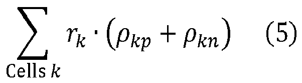
- Constraints: The use of a linear optimization algorithm implies that all the constraints have to be linear with respect to the variables. To be as general as possible there are three types of constraints:
- the ones that are related to the boundaries of the optimization variables,
- the ones that come from the magnetic field specifications,
- the ones that implement the specifications related to the coil manufacturability.
- Boundaries constraints: Variable's boundaries are immediately converted to linear inequality constraints. The boundaries come from the tolerated maximal current density in each cell. Starting from (3), these constraints are formulated as follows:


for each cell k of the design region. - Magnetic constraints: To specify the magnetic constraints, the finite elements method is used to formulate the equations. Referring to publication «T. Labbé and B. Dehez, "Convexity-oriented mapping method for the topology optimization of electromagnetic devices composed of iron and coils," IEEE Transactions on Magnetics, vol. 46,n°. 5, pp. 1177 - 1185, Dec. 2009.» we can write the relation :

with µ the vector of the magnetic permeability, u the magnetic vector potential, j the vector of the local current densities, M and C the finite element matrices. Considering an active shielding or a passive shielding combined with an active shielding ensuring that, for the nominal field, the ferromagnetic parts do not saturate, the equation (8) establishes a linear relation between the local current densities and the magnetic vector potential since the magnetic permeability can be supposed independent of the current level. The magnetic field required by the optimization problem can obtained from equation (8) through:

with F i the rotational operator giving the component i of V × u, b i the vector of the component i of the local fields. As the rotational operators are linear, the relation between the magnetic field and the design variables, linked to the local current densities through linear equation (3), is also linear.
The magnetic constraints of the problem enclose all the magnetic specifications listed above, the first linked to the field distribution in the good field region and the second linked to the field amplitude in the low field region. - Good field region constraints: The distribution in the GFR has to be constrained with a specified tolerance. To reduce computer memory consumption, this constraint may be applied only to some control points, uniformly distributed in the GFR. For the control points k, the magnetic field are imposed with the tolerance δBg ; the constraints takes the form:

with
- Low field region constraints: In the same way, the low field constraint may be applied only to some control points for which a maximal magnetic field is imposed. These points are uniformly distributed on the inner limit of the LFR. For the control point k, the constraint takes the form:

This formulation being not linear, it is transformed to the linear following conservative formulation:
- Coils constraints: As discussed previously, a particular attention has to be taken to the coils: the coils should preferably be planar and their ends should preferably not pass in the GFR. To implement these constraints, the design region is divided in four areas, as shown on
Fig.1b : Area 'A' is the area above a plane parallel to the path plane, and located above the separation region; Area 'C' is the corresponding region below the path plane; areas 'B' and 'D' are at the left and right of the separation region, between areas 'A' and 'C'. Areas 'B' and 'D' are at the inner and outer side respectively of the curve of the curved path of the particles. In each of these areas and for each line parallel to the path plane in these areas, the sum of the current in each cell located on these lines is imposed to zero. If all the cells have the same surface, this constraint can be reduced, for a given lines i of area j, to:
- The applicant found that it was possible to meet all above requirements and obtain improved solutions by using the optimization method.
Fig.3.1 to 3.13 are radial-axial sectional views of various embodiments of magnets according to the invention, obtained by the method of the invention under different conditions and constraints explained hereunder. In all these figures, the section of the coils where the current flows outwards the radial-axial plane are represented in black, the sections of the coils where the current flows in the opposite direction are represented in white. In the coil sections, the current density is uniform, and may be obtained by a plurality of individual conductors wound in coils, as known in the art. First to tenth coils are designated byreference numbers 210 to 300, respectively. The granularity of the outer shape of the coils results from the cell discretization (i.e. the mesh size) used in the optimization. The applicant has observed that when performing the optimization with different mesh size, results showing very similar shapes are obtained. It will be understood that a finer granularity may be obtained at the cost of more computing time and memory, but that the in the actual implementation, these shapes may be smoothed without impairing the quality of the magnets. -
Fig.2 is a perspective view of a section of thecoils -
Fig.3.1 shows a section of the coil ofFig.2 It is to be observed that the sections of the first and second coils have an outer shape limited by a linear portion on a side towards the path plane, and parallel thereto, and a curved portion in the opposite direction. This feature is present in all other examples 3.2 to 3.13 discussed below. -
Fig.3.2 shows the result obtained with same conditions as inFig.3.1 except that the low magnetic field region LFR is outside a rectangular limit where no field limit is imposed and the design region has an rectangular outer limit. -
Fig.3.3 shows the result obtained with same conditions as inFig.3.1 except that the low magnetic field region LFR is outside a truncated circular limit where no field limit is imposed and the design region has a truncated circular outer limit. -
Fig.3.4 shows the result obtained with same conditions as inFig.3.1 except that the first region (good field region GFR) is a circular area. - In these four solutions of the method, one observes similar structure of the coils: a first set of coils, the pole coils, producing a magnetic field for guiding the particles, comprising
first coil 210 andsecond coil 220. At the sides of the path are a second set of coils, the flux return coils, comprising third 230 and fourth 240 coils. The shape of the coil sections are similar, varying only in dependence of the shape (square, circular or others) of the inner and outer limit of the design region. -
Fig.3.5 and 3.6 show the result obtained with same conditions as inFig.3.1 and 3.2 respectively, except that the field gradient has a higher value. One observes the appearance of a third set of coils, the gradient correction coils, comprising fifth 250 and sixth 260 coils. These small coils are located inside the first 210 and second 220 coils, respectively. -
Fig.3.7 ,3.8 and 3.9 show the results obtained with same conditions as inFig.3.1 ,3.2 and 3.3 , respectively, except that the in the low magnetic field region LFR, an upper field limit is imposed. One observes the appearance of a fourth set of coils, shielding coils, comprising seventh 270 and eighth 280 coils. These coils are located symmetrically with respect to the beam guidance plane, at a larger distance of said plane than the first 210 and second 220 coil, at the outer limit of the design region and produce a magnetic field in opposite direction to the field produced by the first and second coils. -
Fig.3.10 shows the result obtained with same conditions as inFig.3.7 except that a lower value for the upper field limit is imposed in the low magnetic field region LFR. One observes the appearance of a fifth set of coils, the shielding correction coils, comprising ninth 290 and tenth 300 coils. These coils are located at an outer side of said third and fourth coils respectively, and produce a magnetic field in opposite direction perpendicular to said plane along said path. The inner part of these coils are next to the outer parts of the third and fourth coils, while the outer parts of these coils are near the outer limit of the design region. -
Fig.3.11 shows the result obtained with same conditions as inFig.3.7 with the additional feature that the coils are segmented in layers parallel to the path plane. -
Fig.3.12 shows the result obtained with same conditions as inFig.3.11 with the additional feature that each coil are approximated by a plurality of rectangular cross section coils. -
Fig.3.13 shows the result obtained with same conditions as inFig.3.8 with the additional feature that the upper field limit in the LFR is such that apassive shielding material 50
located in said region will not reach saturation. In these conditions, the magnet will behave linearly, i.e. the magnetic field value in any point in space will be proportional to the current density in the electrical conductors. - The applicant has observed that the shape of the coils remains stable with respect to the parameters. Although the results of
Fig.3.1 to 3.13 have been obtained with the volume of the electrical conductors as the cost function, very similar results would have been obtained with other cost function, such as the magnetic energy stored in the coils, or the overall size of the section of the magnet. The terms and descriptions used herein are set forth by way of illustration only and are not meant as limitations. Those skilled in the art will recognize that many variations are possible within the spirit and scope of the invention as defined in the following claims, and their equivalents, in which all terms are to be understood in their broadest possible sense unless otherwise indicated. As a consequence, all modifications and alterations will occur to others upon reading and understanding the previous description of the invention. In particular, dimensions, materials, and other parameters, given in the above description may vary depending on the needs of the application.
| Bend radius Rb | 2.5 m |
| Bend angle θ b | 90° |
| Good field region size Lb | 0.2 m |
| Insulation thickness Li | 0.05 m |
| Magnet radius Rm | 0.45 m |
| Low field region circle Rl | 0.55 m |

with jk the local current density for cell k, Jmax the maximal tolerated current density in the magnet.
Claims (15)
- Magnet for guiding a beam of charged particles along a curved path in a path plane, comprising- a first (210) and second (220) coil (pole coils) disposed respectively above and below with respect to said path plane, at a first and second distance of said path plane, and adapted for producing a magnetic field in a direction perpendicular to said path plane along said path ;- a third (230) and fourth (240) coil (flux return coils) disposed along said path plane, at an inner and outer side respectively of the curve of said curved path and at a third and fourth distance thereof, and adapted for producing a magnetic field in same direction perpendicular to said path plane along said path;
characterized in that
the section of said first (210) and said second coils (220) have an outer shape limited by a linear portion on a side towards the path plane, and parallel thereto, and a curved portion on the opposite side. - Magnet according claim 1 further comprising a beam guiding tube characterized in that said third (230) and fourth (240) coils have a parts contiguous to said beam guiding tube.
- Magnet according to any of preceding claims characterized in that it further comprises- a fifth (250) and sixth (260) coil (gradient correction coils) disposed symmetrically with respect to said path plane, at said first and second distance of said path plane, inside said first (210) and second (220) coils, and adapted for producing a magnetic field in same direction perpendicular to said path plane along said path.
- Magnet according to any of preceding claims characterized in that it further comprises- a seventh (270) and eigthth (280) coil (shielding coils) disposed symmetrically with respect to said path plane, at a larger distance of said path plane than the first (210) and second (220) coil, and adapted for producing a magnetic field in opposite direction perpendicular to said path plane along said path.
- Magnet according to any of preceding claims characterized in that it further comprises- a ninth (290) and tenth (300) coil (shielding correction coils) disposed along said path plane, at an outer side of said third and fourth coils respectively, and adapted for producing a magnetic field in opposite direction perpendicular to said path plane along said path;
- Magnet according to any claims 4 or 5 characterized in that it further comprises passive shielding material enclosing the coils of the magnet.
- Magnet according to any one of preceding claims characterized in that said coils are adapted for producing a uniform magnetic field in a region enclosed between said first, second, third and fourth coils.
- Magnet according to any one of preceding claims characterized in that said coils are adapted for producing a magnetic field having a uniform component and a component having a gradient along a radial direction of said curved path in a region enclosed between said first, second, third and fourth coils.
- Magnet according to any one of preceding claims characterized in that said coils are planar coils.
- Magnet according to any one of preceding claims characterized in that said coils are a superposition of coils having a rectangular section and approximating coils having a section with a curved portion.
- Magnet according to any one of preceding claims characterized in that said coils have an axisymmetric symmetry along an azimuthal range.
- Method for designing a magnet for guiding a beam of charged particles along a path, comprising the steps of:(a) in a planar section pependicular to a section of said path, dividing the section in :I a first region (GFR) wherein the required magnetic field for guiding the charged particles along said path is defined;II a separation region enclosing said first region;III a design region wherein electrical conductors are provided for producing said required magnetic field when electrical currents are flowing through said electricla conductors, enclosing said separation region;(b) dividing the design region in a set of k cells;(c) selecting a cost function to be minimized, the function being a combination of one or more functions selected in a set comprising:- the surface in said planar section of the electrical conductors needed for producing the required manetic field;- the magnetic energy stored in the electrical conductors;- the outer size of the design region;- the difference between the obtained field and the required magnetic field in said first region;(d) defining a set of constraints to be met while minimizing said function, said set of constraints comprising:- upper and lower limits for the positive and negative currents in each of the cells k;- obtaining the required magnetic field in said first region GFR, within a tolerance;(e) minimising said cost function, while meeting said constraints, by using an optimization algorithm, for obtaining the distibution of electrical currents in said design region.
- Method according to claim 12, characterised in that said step of dividing the section further comprises dividing (IV) a low magnetic field region LFR wherein the magnetic field is lower than a limit, and enclosing said design region; and in that the set of constraints further comprises obtaining a magnetic field lower than said limit in said low magnetic field region LFR.
- Method according to any of claims 12 to 13 characterised in that step of dividing the section further comprises dividing in four areas: area 'A' above a plane parallel to the path plane, and located above the separation region; area 'C' a corresponding region below the path plane; areas 'B' and 'D' at the left and right of the separation region, between areas 'A' and 'C', and in that in each of these areas and for each lineof cells parallel to the path plane in these areas, the sum of the current in each cell located on these lines is zero.
- Magnet obtainable by the method of any of claims 12 to 14.
Priority Applications (2)
| Application Number | Priority Date | Filing Date | Title |
|---|---|---|---|
| EP11180836A EP2568475A1 (en) | 2011-09-10 | 2011-09-10 | Magnet and method for designing a magnet |
| PCT/EP2012/067678 WO2013034776A1 (en) | 2011-09-10 | 2012-09-10 | Magnet and method for designing a magnet |
Applications Claiming Priority (1)
| Application Number | Priority Date | Filing Date | Title |
|---|---|---|---|
| EP11180836A EP2568475A1 (en) | 2011-09-10 | 2011-09-10 | Magnet and method for designing a magnet |
Publications (1)
| Publication Number | Publication Date |
|---|---|
| EP2568475A1 true EP2568475A1 (en) | 2013-03-13 |
Family
ID=46845755
Family Applications (1)
| Application Number | Title | Priority Date | Filing Date |
|---|---|---|---|
| EP11180836A Withdrawn EP2568475A1 (en) | 2011-09-10 | 2011-09-10 | Magnet and method for designing a magnet |
Country Status (2)
| Country | Link |
|---|---|
| EP (1) | EP2568475A1 (en) |
| WO (1) | WO2013034776A1 (en) |
Cited By (2)
| Publication number | Priority date | Publication date | Assignee | Title |
|---|---|---|---|---|
| EP2899708A1 (en) | 2014-01-28 | 2015-07-29 | Siemens Schweiz AG | Combination of buses for a danger management system |
| CN109309410A (en) * | 2017-07-27 | 2019-02-05 | Tdk株式会社 | Coil unit and power supply unit, power receiving device and the Wireless power transmission system for using it |
Families Citing this family (1)
| Publication number | Priority date | Publication date | Assignee | Title |
|---|---|---|---|---|
| CN115982796B (en) * | 2023-01-03 | 2026-04-14 | 上海交通大学 | Method and device for determining distribution form of superconducting magnet material |
Citations (4)
| Publication number | Priority date | Publication date | Assignee | Title |
|---|---|---|---|---|
| US3912182A (en) * | 1973-08-21 | 1975-10-14 | Sony Corp | Apparatus for winding saddle-shaped deflection coil |
| DE19943783A1 (en) * | 1999-09-13 | 2001-03-29 | Siemens Ag | Superconducting device with a multi-pole winding arrangement |
| JP2008085376A (en) * | 2007-12-20 | 2008-04-10 | Mitsubishi Electric Corp | Superconducting magnet device |
| US7812319B2 (en) | 2007-05-04 | 2010-10-12 | Siemens Aktiengessellschaft | Beam guiding magnet for deflecting a particle beam |
Family Cites Families (1)
| Publication number | Priority date | Publication date | Assignee | Title |
|---|---|---|---|---|
| KR100635885B1 (en) * | 2004-12-14 | 2006-10-18 | 한국기초과학지원연구원 | Design Method of Highly Uniform High Magnetic Field Superconducting Magnets |
-
2011
- 2011-09-10 EP EP11180836A patent/EP2568475A1/en not_active Withdrawn
-
2012
- 2012-09-10 WO PCT/EP2012/067678 patent/WO2013034776A1/en not_active Ceased
Patent Citations (4)
| Publication number | Priority date | Publication date | Assignee | Title |
|---|---|---|---|---|
| US3912182A (en) * | 1973-08-21 | 1975-10-14 | Sony Corp | Apparatus for winding saddle-shaped deflection coil |
| DE19943783A1 (en) * | 1999-09-13 | 2001-03-29 | Siemens Ag | Superconducting device with a multi-pole winding arrangement |
| US7812319B2 (en) | 2007-05-04 | 2010-10-12 | Siemens Aktiengessellschaft | Beam guiding magnet for deflecting a particle beam |
| JP2008085376A (en) * | 2007-12-20 | 2008-04-10 | Mitsubishi Electric Corp | Superconducting magnet device |
Non-Patent Citations (6)
| Title |
|---|
| CERESETO R ET AL: "The Winding Method and Model of a Superconducting Bending Dipole for Hadrontherapy", IEEE TRANSACTIONS ON APPLIED SUPERCONDUCTIVITY, IEEE SERVICE CENTER, LOS ALAMITOS, CA, US, vol. 14, no. 2, 1 June 2004 (2004-06-01), pages 585 - 588, XP011117409, ISSN: 1051-8223, DOI: 10.1109/TASC.2004.829980 * |
| JO Y-S ET AL: "Advanced design approach to the high temperature superconducting magnet", CRYOGENICS, ELSEVIER, KIDLINGTON, GB, vol. 41, no. 1, 1 January 2001 (2001-01-01), pages 27 - 33, XP004249247, ISSN: 0011-2275, DOI: 10.1016/S0011-2275(01)00044-3 * |
| M. CONTE ET AL.: "INFN Note", SIS-PUBBLICAZIONI, article "Indirectly cooled superconducting dipole for a ion gantry" |
| SARMA P ET AL: "Modification of cos[theta] coil shape in superconducting dipole magnets for reducing the coil size", REVIEW OF SCIENTIFIC INSTRUMENTS, AIP, MELVILLE, NY, US, vol. 76, no. 1, 17 December 2004 (2004-12-17), pages 13302 - 013302, XP012078987, ISSN: 0034-6748 * |
| T LABBE, B. DEHEZ: "Convexity-oriented mapping method for the topology optimization of electromagnetic devices composed of iron and coils", IEEE TRANSACTIONS ON MAGNETICS, vol. 46, no. 5, December 2009 (2009-12-01), pages 1177 - 1185, XP011298304, DOI: doi:10.1109/TMAG.2009.2037754 |
| THIBAUT LABBE ET AL: "Convexity-Oriented Mapping Method for the Topology Optimization of Electromagnetic Devices Composed of Iron and Coils", IEEE TRANSACTIONS ON MAGNETICS, IEEE SERVICE CENTER, NEW YORK, NY, US, vol. 46, no. 5, 1 May 2010 (2010-05-01), pages 1177 - 1185, XP011298304, ISSN: 0018-9464, DOI: 10.1109/TMAG.2009.2037754 * |
Cited By (3)
| Publication number | Priority date | Publication date | Assignee | Title |
|---|---|---|---|---|
| EP2899708A1 (en) | 2014-01-28 | 2015-07-29 | Siemens Schweiz AG | Combination of buses for a danger management system |
| CN109309410A (en) * | 2017-07-27 | 2019-02-05 | Tdk株式会社 | Coil unit and power supply unit, power receiving device and the Wireless power transmission system for using it |
| CN109309410B (en) * | 2017-07-27 | 2022-04-12 | Tdk株式会社 | Coil unit, and power supply device, power receiving device, and wireless power transmission system using same |
Also Published As
| Publication number | Publication date |
|---|---|
| WO2013034776A1 (en) | 2013-03-14 |
Similar Documents
| Publication | Publication Date | Title |
|---|---|---|
| US12591028B2 (en) | Resistive electromagnet systems and methods | |
| US8902030B2 (en) | Device for generating an orientable and locally uniform magnetic field | |
| Takayama et al. | Design and magnetic field measurement of the superconducting magnets for the next-generation rotating gantry | |
| US11199599B2 (en) | Magnet assembly comprising closed superconducting HTS shims | |
| WO2011065455A1 (en) | Gradient coil, magnetic resonance imaging device, and method for designing coil pattern | |
| Jiang et al. | Total AC loss measurements in a six strand Roebel cable carrying an AC current in an AC magnetic field | |
| EP2568475A1 (en) | Magnet and method for designing a magnet | |
| US7427908B1 (en) | Magnetic shimming configuration with optimized turn geometry and electrical circuitry | |
| US6909348B2 (en) | Low-leakage magnetic-field magnet and shield coil assembly | |
| Crawford | The physical meaning of the magnetic scalar potential and its use in the design of hermetic electromagnetic coils | |
| US9793036B2 (en) | Low temperature superconductor and aligned high temperature superconductor magnetic dipole system and method for producing high magnetic fields | |
| Planche et al. | Conformal mapping approach to dipole shim design | |
| Kim | A scaling law for the magnetic fields of superconducting undulators | |
| Baird et al. | Optimized magnetic design of superconducting magnets for heavy ion rotating gantries | |
| Todesco | Magnetic design of superconducting magnets | |
| Du et al. | Design of an emittance compensation superconducting magnet package for LCLS-II-HE's SRF photo-injector | |
| Mezentsev et al. | Planar superconducting undulator with neutral poles | |
| Fatehi | Compact high-temperature superconducting magnets for laser-plasma accelerator beam capture and transport | |
| Han et al. | Study of magnetic fringe fields and interference effects on beam dynamics for proton facility gantry | |
| Kim et al. | A novel magnetic field active shim method for air-core high-temperature superconducting quadruple magnet | |
| US20110133739A1 (en) | Arrangement of coils for mri apparatus | |
| Tsoupas et al. | A state of the art current-septum dipole magnet | |
| Kim et al. | Experimental test of the magnetic field active shimming method for air-core HTS quadruple magnet | |
| Galayda et al. | Beam optical properties of the NSLS dipoles | |
| Green | Design parameters for a 7.2 tesla bending magnet for a 1.5 GeV compact light source |
Legal Events
| Date | Code | Title | Description |
|---|---|---|---|
| PUAI | Public reference made under article 153(3) epc to a published international application that has entered the european phase |
Free format text: ORIGINAL CODE: 0009012 |
|
| AK | Designated contracting states |
Kind code of ref document: A1 Designated state(s): AL AT BE BG CH CY CZ DE DK EE ES FI FR GB GR HR HU IE IS IT LI LT LU LV MC MK MT NL NO PL PT RO RS SE SI SK SM TR |
|
| AX | Request for extension of the european patent |
Extension state: BA ME |
|
| STAA | Information on the status of an ep patent application or granted ep patent |
Free format text: STATUS: THE APPLICATION IS DEEMED TO BE WITHDRAWN |
|
| 18D | Application deemed to be withdrawn |
Effective date: 20130914 |