EP2568401A2 - Method for predicting the impact on an aircraft of debris shed off from it - Google Patents
Method for predicting the impact on an aircraft of debris shed off from it Download PDFInfo
- Publication number
- EP2568401A2 EP2568401A2 EP12182151A EP12182151A EP2568401A2 EP 2568401 A2 EP2568401 A2 EP 2568401A2 EP 12182151 A EP12182151 A EP 12182151A EP 12182151 A EP12182151 A EP 12182151A EP 2568401 A2 EP2568401 A2 EP 2568401A2
- Authority
- EP
- European Patent Office
- Prior art keywords
- aircraft
- debris
- predetermined
- computer
- trajectories
- Prior art date
- Legal status (The legal status is an assumption and is not a legal conclusion. Google has not performed a legal analysis and makes no representation as to the accuracy of the status listed.)
- Withdrawn
Links
Images


Classifications
-
- G—PHYSICS
- G06—COMPUTING OR CALCULATING; COUNTING
- G06F—ELECTRIC DIGITAL DATA PROCESSING
- G06F30/00—Computer-aided design [CAD]
- G06F30/10—Geometric CAD
- G06F30/15—Vehicle, aircraft or watercraft design
-
- G—PHYSICS
- G06—COMPUTING OR CALCULATING; COUNTING
- G06F—ELECTRIC DIGITAL DATA PROCESSING
- G06F30/00—Computer-aided design [CAD]
- G06F30/20—Design optimisation, verification or simulation
Definitions
- the present invention relates to a method for predicting the impact on an aircraft of debris shed off from it.
- the present invention is directed to solving this problem.
- An object of this invention to provide a computer-aided method to predict the location of an impact of an aircraft of debris shed off from it.
- the velocity of the body at the time of impact is also calculated.
- the body is a flat plate.
- a method which, on the one hand, is adapted to the nature of the debris shed off from an aircraft and, on the other hand, can take advantage of available knowledge about the dynamics of flat plates in a fluid medium, and particularly on aerodynamic models (like the ESDU or Hoerner) that apply to them.
- the range of the departure angle of the debris with respect to any of the three coordinate axes is comprised between - 90° and +90°.
- the fluid field in which occurs the detachment of the debris from the aircraft can be an uniform fluid field of a predetermined speed (if a simplification of the problem is wanted or if previous analysis to refine the method shall be done) or a real fluid field.
- the above mentioned objects are achieved by a computer program adapted to execute the above-mentioned method.
- each of said trajectories is obtained as a collection of points identified by its coordinates.
- a computer program that provides said trajectories in an optimum format to calculate their impacts on the surface of the aircraft.
- a surface representation of the aircraft on triangular meshes is used to calculate the impact of said trajectories on the aircraft.
- Reference coordinates system The body axis and the earth axis shown respectively in Figures 1 and 2 .
- C DD 1 Q has been used in some studies about ice-shedding such as for example: AIAA 2001-0680 (Analytical Prediction of Trajectories of Ice Pieces after Release in an Airstream), but there is not any reference to the origin of this terms.
- the dimensions of C DD 1 are [ M ⁇ L 2 ⁇ T - 1 ] .
- C DD2 Q 2 results from the integration of the drag forces actuating on a rotating plate.
- the dimensions of C DD2 are: [ M ⁇ L 2 ]
- the term 1 4 ⁇ C DD3 P, d 2 V T S, is the one commonly used in the aircraft flight dynamics.
- the coefficient C DD3 (Roll damping) is adimensional. It has the drawback that when that does not operate when the translational velocity is zero; which means that if a flat plate only rolls will never stop.
- V XA V YA V ZA V XT V YT V ZT ⁇ COS ⁇ SIN ⁇ 0 - SIN ⁇ COS ⁇ 0 0 1 ⁇ COS ⁇ 0 - SIN ⁇ 0 1 0 SIN ⁇ 0 COS ⁇ ⁇ 1 0 0 0 COS ⁇ SIN ⁇ 0 - SIN ⁇ COS ⁇
- Figures 3 and 4 respectively show the momentum equations for, respectively, a circular plate and a square plate.
- an important aspect of the present invention is the calculation of many trajectories of the debris varying randomly the initial starting conditions following the style of Monte Carlo methods,.
- the debris under analysis could be taken as a data rather than a variable the dimensions of the plate if the debris under analysis has a low probability of rupture and, conversely, the density of the plate might be taken as a variable rather than as data if the debris under analysis could be of a different material (such as a piece of ice or a piece of metal that could detached from a given area of the aircraft).
- the biggest advantage of the method according to the invention is the possibility of analyzing the case in question considering different input data and calculating a large number of trajectories in a computationally reasonable time at low costs due to the use of an analytical model.
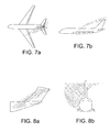
- Figures 7a and 7b graphically illustrate the results obtained by applying the method of the present invention to predict the impact on an aircraft of a slat shed off from the wing.
- the slat was represented by a flat plate of dimensions 0.13 m ⁇ 0.0325 m ⁇ 0.02 m and density 59 kg/m 3 .
- the trajectories were calculated randomly varying initial conditions in the following ranges:
- the result obtained was a probability of impact on the vertical tail plane of 11.25%.
- Figures 8a and 8b illustrate graphically the results obtained using the method of the present invention to predict the impact on the aircraft of a deflector shed off from the wing.
- the deflector was represented by a flat plate of dimensions 1.69m x0.56mx0.1m and density 105.88 kg/m3.
Landscapes
- Engineering & Computer Science (AREA)
- Physics & Mathematics (AREA)
- Geometry (AREA)
- Theoretical Computer Science (AREA)
- General Physics & Mathematics (AREA)
- Computer Hardware Design (AREA)
- Evolutionary Computation (AREA)
- General Engineering & Computer Science (AREA)
- Automation & Control Theory (AREA)
- Aviation & Aerospace Engineering (AREA)
- Computational Mathematics (AREA)
- Mathematical Analysis (AREA)
- Mathematical Optimization (AREA)
- Pure & Applied Mathematics (AREA)
- Aerodynamic Tests, Hydrodynamic Tests, Wind Tunnels, And Water Tanks (AREA)
- Management, Administration, Business Operations System, And Electronic Commerce (AREA)
Abstract
Description
- The present invention relates to a method for predicting the impact on an aircraft of debris shed off from it.
- As is well known from the surface of an aircraft can be shed off different pieces of material (plates, pieces of ice, covers ...) who pose a risk when they hit other parts of the surface of the aircraft. In fact several catastrophic accidents are known due to the impact of debris shed off from the own aircraft.
- These risks are especially important in aircrafts fitted with open rotor propulsion engines in the rear part in which events can happen where a blade of one of the propeller engines comes off and hits the fuselage, where a part of the rotor of the engine brakes, it is released and hits the fuselage, or where an ice shedding created in the tips of the blades can be thrown at high speed over the fuselage.
- The design of these aircraft must therefore take account of these events and ensure their ability to maintain stability and carry out a safe landing of the aircraft, being for that very important to predict the possible trajectories.
- While there are known wind tunnel tests designed to predict aircraft zones affected by specific pieces detached from the aircraft it is not known any computer-aided method to predict areas affected by impacts of debris shed off from the aircraft.
- The present invention is directed to solving this problem.
- An object of this invention to provide a computer-aided method to predict the location of an impact of an aircraft of debris shed off from it.
- In one aspect, this and other objects are achieved by a method comprising the following steps:
- a) providing the nominal position on the aircraft of said debris before its detachment;
- b) represent the debris by a body of a size and density appropriate to its characteristics;
- c) calculating a predetermined number of trajectories in three dimensions of said body in a predetermined fluid field when it is detached from the aircraft using an analytical model for calculating said trajectories which comprises equations of motion of said body resulting from the aerodynamic forces and moments acting on it and including one or more damping coefficients of its angular velocity, and randomly varying one or more of the following initial conditions: the initial position of the body within a predetermined space around said nominal position; the dimensions of the body within a set of predetermined values, the damping coefficients of the angular velocity within a predetermined set of values, the initial angles of roll, pitch and yaw within a predetermined range of values;
- d) calculating the points of impact of said trajectories in the aircraft.
- In embodiments of the method the velocity of the body at the time of impact is also calculated. Hereby it is achieved a method that provides a basic information for the design of those parts of the aircraft affected by potential impacts of debris shed off from the aircraft.
- In embodiments of the method, the body is a flat plate. Hereby it is achieved a method which, on the one hand, is adapted to the nature of the debris shed off from an aircraft and, on the other hand, can take advantage of available knowledge about the dynamics of flat plates in a fluid medium, and particularly on aerodynamic models (like the ESDU or Hoerner) that apply to them.
- In embodiments of the method, the range of the departure angle of the debris with respect to any of the three coordinate axes is comprised between - 90° and +90°. Hereby it is achieved a method adapted to the nature of the problem given that the angle of departure is an important variable for calculating the possible trajectories of the debris.
- In embodiments of the method, the fluid field in which occurs the detachment of the debris from the aircraft can be an uniform fluid field of a predetermined speed (if a simplification of the problem is wanted or if previous analysis to refine the method shall be done) or a real fluid field.
- In another aspect, the above mentioned objects are achieved by a computer program adapted to execute the above-mentioned method.
- In embodiments of the computer program, each of said trajectories is obtained as a collection of points identified by its coordinates. Hereby it is achieved a computer program that provides said trajectories in an optimum format to calculate their impacts on the surface of the aircraft.
- In embodiments of the computer program, a surface representation of the aircraft on triangular meshes is used to calculate the impact of said trajectories on the aircraft. Hereby it is achieved a very efficient computer program for calculating said impacts on the surface of the aircraft.
- Other features and advantages of the present invention will become apparent from the following detailed description of embodiments illustrative of its object, along with the accompanying figures.
-
-
Figures 1 and 2 illustrate the reference systems used in the analytical model to calculate trajectories used in the method of the present invention. -
Figures 3 to 6 illustrate various aspects of the analytical model for calculating trajectories of flat square plates. -
Figures 7a and 7b show the results obtained in a first example of execution of the method of the present invention. -
Figures 8a and 8b show the results obtained in a second example of execution of the method of the present invention. - Reference coordinates system: The body axis and the earth axis shown respectively in
Figures 1 and 2 . - Nomenclature used:
- m
- Mass of the object.
- g
- Gravity constant.
- CN
- Normal force coefficient.
- C DD1, C DD2, C DD3
- Damping coefficients of rotation.
- d
- Characteristic dimension.
- ρ
- Density of air.
- IXX IXY IXZ IYX IYY IYZ IZX IZY IZZ
- Inertia Matrix.
- Variables in earth axis:
- XW, YW, ZW
- Position of gravity center.
- UW, VW, WW
- Linear velocity.
- Φ,θ,ψ
- Orientation Pitch (X), Roll (Y), Yaw (Z). They are applied in this order: Yaw, Roll, Pitch.
- VXT,VY,VZT
- Speed of air.
- Variables in body axis:
- U, V, W
- Linear velocity.
- U',V',W'
- Linear acceleration.
- VXA,VYA,VZA
- Velocity of air.
- FX,FY,FZ
- Aerodynamic forces.
- L, M, N
- Aerodynamic moments.
- P,Q,R
- Angular velocity.
- P',Q',R'
- Angular acceleration.
- XCP,YCP
- Pressure centre coordinates.
- Equations in body axis:
- Force equations:



- Moment equations:


- Aerodynamic forces:


- Aerodynamic moments:



- Simplifying:


- In these equations have been included terms that contribute to the damping of the angular velocity with three damping coefficients CDD1, CDD2 and CDD3 that can be used or not depending on the circumstances of each case.
- The term C DD1 Q , has been used in some studies about ice-shedding such as for example: AIAA 2001-0680 (Analytical Prediction of Trajectories of Ice Pieces after Release in an Airstream), but there is not any reference to the origin of this terms. The dimensions of C DD1 are [M·L2·T -1].
- El term CDD2Q2 results from the integration of the drag forces actuating on a rotating plate. The dimensions of CDD2 are: [M·L2 ]
- The term

- Dynamic equations:


- Wind velocity in the body axis:

- Velocity with respect to the earth axis:

- Position with respect to the earth axis:



- In the above-mentioned equations the values of the normal force coefficient CN and of the position of the pressure centre XCP,YCP are taken from a suitable aerodynamic model for the case under analysis.
- Good results were achieved using as representative bodies of the debris shed off the aircraft flat plates of, preferably, square and circular shapes with a size and density determined on the basis of the material of the debris under analysis.
-
Figures 3 and4 respectively show the momentum equations for, respectively, a circular plate and a square plate. - The calculation of the coefficient C DD2 of a circular flat plate as the one shown in
Figure 5 is the following:
- MR=Dx ; dMR=dDx ; dMR=Cd ρ(px) 2 ydx · x ; dMR=Cd ρp2x3y · dx
- Making the change: y=R · cosα : x = R · sinα ; dx=R · cosα · dα
- dMR=Cd ρ·p2·R3sin3 α·R2cos2α · dα
- Calling:

- Dimensions:


- The calculation of the coefficient CDD2 of a square flat plate as the one shown in
Figure 6 is the following:


- Calling:

- Dimensions:


- Two suitable aerodynamic models for flat plates are:
- ESDU (Ref. ESDU Fluid forces and moments on flat plates. Data ítem 70015)
- Hoerner ( Hoerner, S. F. and Borst, H. V., Fluid-Dynamic Lift: Practical Information on Aerodynamic and Hydrodynamic Lift, Hoerner Fluid Dynamics, 1975
- As we have seen an important aspect of the present invention is the calculation of many trajectories of the debris varying randomly the initial starting conditions following the style of Monte Carlo methods,.
- In case it would be wanted to analyze, for example, the areas of likely impact on an aircraft of debris representable by a square plate, it could be used as input data:
- The density of the plate;
- The nominal position of the plate;
- The fluid field where the plate moves;
- The geometry of the surface of the aircraft.
- Regarding the initial conditions to be varied randomly, one or more of the following could be used:
- The initial position of the plate within a prefixed space (for example a cube) around the nominal position taken as a data;
- The dimensions of the plate within a set of predetermined values;
- The damping coefficients used in the analytical model within a set of predetermined values;
- The departure angles of the square plate in all three axes (pitch, roll, yaw) within a predetermined range.
- Using the above-mentioned analytical model a predetermined number of trajectories (usually very large) are calculated varying randomly the values of said initial conditions.
- From these trajectories and the geometry of the aircraft the impact points are calculated and also its speed allowing the analysis of the probability of impacts on different areas of the aircraft and its effects.
- As the skilled man will readily understand the former division between data and variables shall not be understood rigidly but established taking into account the particularities of the case under analysis.
- For example it could be taken as a data rather than a variable the dimensions of the plate if the debris under analysis has a low probability of rupture and, conversely, the density of the plate might be taken as a variable rather than as data if the debris under analysis could be of a different material (such as a piece of ice or a piece of metal that could detached from a given area of the aircraft).
- The biggest advantage of the method according to the invention, particularly in relation to wind tunnel tests, is the possibility of analyzing the case in question considering different input data and calculating a large number of trajectories in a computationally reasonable time at low costs due to the use of an analytical model.
- In that sense, it is important that the implementation of the method in a computer program allows both the graphical representation of the calculated trajectories and an easy calculation of their impacts on the aircraft.
- To this end, it is convenient firstly to obtain such trajectories as a collection of points identified by its coordinates so that they can be stored in IGES ("Initial Graphics Exchange Specification") files. Secondly, it is desirable to have the geometry of the aircraft in the form of triangular meshes to calculate and plot the impacts using CAD tools such as CATIA.
-
Figures 7a and 7b graphically illustrate the results obtained by applying the method of the present invention to predict the impact on an aircraft of a slat shed off from the wing. - The slat was represented by a flat plate of dimensions 0.13 m× 0.0325 m× 0.02 m and density 59 kg/m3.
- The trajectories were calculated randomly varying initial conditions in the following ranges:
- Angle of Yaw: From 29° to 43°.
- Angle of roll: From 2° to 11°.
- Angle Pitch: From 0° to 20°.
- The result obtained was a probability of impact on the vertical tail plane of 11.25%.
-
Figures 8a and 8b illustrate graphically the results obtained using the method of the present invention to predict the impact on the aircraft of a deflector shed off from the wing. - The deflector was represented by a flat plate of dimensions 1.69m x0.56mx0.1m and density 105.88 kg/m3.
- 500,000 trajectories were calculated randomly varying the initial conditions in the following ranges:
- Yaw angle: +/- 90°.
- Roll angle: +/- 90°.
- Pitch angle: +/- 90°.
- The results obtained were:
- Left horizontal tail plane: Probability of impact 0.32%, average impact velocity 135 m/s.
- Right horizontal tail plane: Probability of impact 0.032%, average impact velocity 144 m/s.
- Vertical tail plane: Probability of impact 0.28%, average impact velocity 133 m/s.
- Fuselage: Probability of impact 0.94%, average impact velocity 73 m/s.
- Although the present invention has been fully described in connection with preferred embodiments, it is evident that modifications may be introduced within the scope thereof, not considering this as limited by these embodiments, but by the contents of the following claims.

Claims (11)
- Computer-aided method to predict the location of an impact on an aircraft of debris of predetermined characteristics shed off from the own aircraft comprising the following steps:a) providing the nominal position on the aircraft of said debris before its detachment;b) represent the debris by a body of a size and density appropriate to its characteristics;c) calculating a predetermined number of trajectories in three dimensions of said body in a predetermined fluid field when it is detached from the aircraft using an analytical model for calculating said trajectories which comprises equations of motion of said body resulting from the aerodynamic forces and moments acting on it and including one or more damping coefficients of its angular velocity, and randomly varying one or more of the following initial conditions:- the initial position of the body within a predetermined space around said nominal position;- the dimensions of the body within a set of predetermined values;- the damping coefficients of the angular velocity within a predetermined set of values;- the initial angles of roll, pitch and yaw within a predetermined range of values;d) calculating the points of impact of said trajectories in the aircraft.
- Computer-aided method according to claim 1, wherein the velocity of the body at the time of impact is also calculated.
- Computer-aided method according to any of claims 1-2, wherein the body is a flat plate.
- Computer-aided method according to claim 3, wherein the normal force coefficient CN and the position of the pressure centre XCP,YCP corresponding to said flat plate are taken from a predetermined aerodynamic model.
- Computer-aided method according to claim 4, wherein said predetermined aerodynamic model is one of the following:- the ESDU model;- the Hoerner model.
- Computer-aided method according to any of claims 1-5, wherein the range of the departure angle of the debris with respect to any of the three coordinate axes is comprised between -90° and +90°.
- Computer-aided method according to any of claims 1-6, wherein the fluid field in which occurs the detachment of the debris from the aircraft is an uniform fluid field of a predetermined speed.
- Computer-aided method according to any of claims 1-6, wherein the fluid field in which occurs the detachment of the debris from the aircraft is a real fluid field.
- A computer program adapted to execute a method according to any of claims 1-8.
- A computer program according to claim 9, wherein each of said trajectories is obtained as a collection of points identified by its coordinates.
- A computer program according to claim 10, wherein a surface representation of the aircraft on triangular meshes is used to calculate the impact of said trajectories on the aircraft.
Applications Claiming Priority (1)
| Application Number | Priority Date | Filing Date | Title |
|---|---|---|---|
| ES201131463 | 2011-09-06 |
Publications (2)
| Publication Number | Publication Date |
|---|---|
| EP2568401A2 true EP2568401A2 (en) | 2013-03-13 |
| EP2568401A3 EP2568401A3 (en) | 2016-11-16 |
Family
ID=46982423
Family Applications (1)
| Application Number | Title | Priority Date | Filing Date |
|---|---|---|---|
| EP12182151.6A Withdrawn EP2568401A3 (en) | 2011-09-06 | 2012-08-29 | Method for predicting the impact on an aircraft of debris shed off from it |
Country Status (2)
| Country | Link |
|---|---|
| US (1) | US9342635B2 (en) |
| EP (1) | EP2568401A3 (en) |
Cited By (1)
| Publication number | Priority date | Publication date | Assignee | Title |
|---|---|---|---|---|
| CN106326664A (en) * | 2016-08-30 | 2017-01-11 | 湖北航天技术研究院总体设计所 | Method and system for determining airborne load of missile distribution |
Families Citing this family (8)
| Publication number | Priority date | Publication date | Assignee | Title |
|---|---|---|---|---|
| CN103207933B (en) * | 2013-03-20 | 2016-01-20 | 牟全臣 | Airplane airfoil pressure intensity mapping method and system |
| CN103604615B (en) * | 2013-11-06 | 2017-02-08 | 北京卫星环境工程研究所 | Performance verification method of contact copying protection device of satellite large-aperture engine |
| FR3071629B1 (en) * | 2017-09-25 | 2022-01-28 | Safran Aircraft Engines | ESTABLISHMENT OF AN EQUIPMENT SIZING SPECIFICATION FOR A TURBOMACHINE STRUCTURE |
| CN110874055B (en) * | 2018-08-31 | 2023-04-14 | 中国运载火箭技术研究院 | Prediction and control method of hypersonic vehicle separation process under the action of two-phase flow field |
| CN109507877B (en) * | 2018-11-22 | 2020-12-08 | 北京航空航天大学 | A safety assessment method for aircraft trajectory planning |
| US11975828B2 (en) * | 2021-06-30 | 2024-05-07 | Textron Innovations Inc. | System and method for calibrating torque measurements |
| CN118410612B (en) * | 2024-01-26 | 2025-03-28 | 中国电子产品可靠性与环境试验研究所((工业和信息化部电子第五研究所)(中国赛宝实验室)) | Method, device, computer equipment and storage medium for determining risk probability value |
| CN119354475B (en) * | 2024-12-26 | 2025-03-14 | 中国空气动力研究与发展中心高速空气动力研究所 | Method for correcting project-applicable store separation track |
Family Cites Families (1)
| Publication number | Priority date | Publication date | Assignee | Title |
|---|---|---|---|---|
| GB2475926B (en) * | 2009-12-07 | 2011-10-19 | Phs Space Ltd | Debris impact mitigation apparatus for spacecraft |
-
2012
- 2012-01-13 US US13/349,974 patent/US9342635B2/en not_active Expired - Fee Related
- 2012-08-29 EP EP12182151.6A patent/EP2568401A3/en not_active Withdrawn
Non-Patent Citations (1)
| Title |
|---|
| None |
Cited By (1)
| Publication number | Priority date | Publication date | Assignee | Title |
|---|---|---|---|---|
| CN106326664A (en) * | 2016-08-30 | 2017-01-11 | 湖北航天技术研究院总体设计所 | Method and system for determining airborne load of missile distribution |
Also Published As
| Publication number | Publication date |
|---|---|
| US9342635B2 (en) | 2016-05-17 |
| EP2568401A3 (en) | 2016-11-16 |
| US20130060538A1 (en) | 2013-03-07 |
Similar Documents
| Publication | Publication Date | Title |
|---|---|---|
| US9342635B2 (en) | Method for predicting the impact on an aircraft of debris shed off from it | |
| Cao et al. | Aircraft flight characteristics in icing conditions | |
| Müller et al. | UAV icing: Numerical simulation of propeller ice accretion | |
| Cheng et al. | A numerical study on the attitudes and aerodynamics of freely falling hexagonal ice plates | |
| Cao et al. | Helicopter flight characteristics in icing conditions | |
| Jingyu et al. | Numerical simulation of a UAV impacting engine fan blades | |
| Lindner et al. | Uav icing: Numerical simulation of icing effects on wing and empennage | |
| Peters et al. | On the Application of an Actuator Line Model for Rotorcraft Outwash Predictions | |
| Shinan et al. | Numerical simulation of ice shedding motion characteristic on airfoil surface | |
| Jasion et al. | Prediction of brownout inception beneath a full-scale helicopter downwash | |
| Forsyth et al. | Application of the morphogenetic approach to 1st AIAA ice prediction workshop test cases | |
| Czyż et al. | Numerical analysis of the influence of particular autogyro parts on the aerodynamic forces | |
| Hospers et al. | Numerical simulation of SLD ice accretions | |
| Jung et al. | Ice accretion effect on the aerodynamic characteristics of KC-100 aircraft | |
| de Castro Santos et al. | A simulation model for ice impact risk evaluation | |
| Meakin | Multiple-body proximate-flight simulation methods | |
| Lennie et al. | Development of ice throw model for wind turbine simulation software QBlade | |
| Bai et al. | Analysis of the influence of different droplet size distribution on wing impact characteristics and ice shape | |
| Lofthouse et al. | Static and dynamic simulations of a generic UCAV geometry using the kestrel flow solver | |
| Garrick et al. | Simulation of landing maneuvers of rotorcraft in brownout conditions | |
| Kohlman et al. | Analytical prediction of trajectories of ice pieces after release in an airstream | |
| Anthony et al. | Rotor ice shedding and trajectory analyses in forward flight | |
| Liu et al. | Research on airworthiness compliance verification method for damage to civil aircraft tail wings caused by ice shedding | |
| Morton et al. | Multidisciplinary applications of detached-eddy simulation to separated flows at high Reynolds numbers (challenge 92) | |
| Ghoreyshi et al. | Computational Study of Vortex Interaction Characteristics of Multi-Swept Wings at Subsonic Speeds |
Legal Events
| Date | Code | Title | Description |
|---|---|---|---|
| PUAI | Public reference made under article 153(3) epc to a published international application that has entered the european phase |
Free format text: ORIGINAL CODE: 0009012 |
|
| AK | Designated contracting states |
Kind code of ref document: A2 Designated state(s): AL AT BE BG CH CY CZ DE DK EE ES FI FR GB GR HR HU IE IS IT LI LT LU LV MC MK MT NL NO PL PT RO RS SE SI SK SM TR |
|
| AX | Request for extension of the european patent |
Extension state: BA ME |
|
| PUAL | Search report despatched |
Free format text: ORIGINAL CODE: 0009013 |
|
| AK | Designated contracting states |
Kind code of ref document: A3 Designated state(s): AL AT BE BG CH CY CZ DE DK EE ES FI FR GB GR HR HU IE IS IT LI LT LU LV MC MK MT NL NO PL PT RO RS SE SI SK SM TR |
|
| AX | Request for extension of the european patent |
Extension state: BA ME |
|
| RIC1 | Information provided on ipc code assigned before grant |
Ipc: G06F 17/50 20060101AFI20161013BHEP |
|
| STAA | Information on the status of an ep patent application or granted ep patent |
Free format text: STATUS: REQUEST FOR EXAMINATION WAS MADE |
|
| 17P | Request for examination filed |
Effective date: 20170512 |
|
| RBV | Designated contracting states (corrected) |
Designated state(s): AL AT BE BG CH CY CZ DE DK EE ES FI FR GB GR HR HU IE IS IT LI LT LU LV MC MK MT NL NO PL PT RO RS SE SI SK SM TR |
|
| STAA | Information on the status of an ep patent application or granted ep patent |
Free format text: STATUS: THE APPLICATION IS DEEMED TO BE WITHDRAWN |
|
| 18D | Application deemed to be withdrawn |
Effective date: 20200303 |