EP2568400A1 - Method and system for designing an assembly of objects in a system of computer-aided design - Google Patents
Method and system for designing an assembly of objects in a system of computer-aided design Download PDFInfo
- Publication number
- EP2568400A1 EP2568400A1 EP11306115A EP11306115A EP2568400A1 EP 2568400 A1 EP2568400 A1 EP 2568400A1 EP 11306115 A EP11306115 A EP 11306115A EP 11306115 A EP11306115 A EP 11306115A EP 2568400 A1 EP2568400 A1 EP 2568400A1
- Authority
- EP
- European Patent Office
- Prior art keywords
- representation
- computer
- logical
- logical component
- dimensional
- Prior art date
- Legal status (The legal status is an assumption and is not a legal conclusion. Google has not performed a legal analysis and makes no representation as to the accuracy of the status listed.)
- Ceased
Links
Images



Classifications
-
- G—PHYSICS
- G06—COMPUTING OR CALCULATING; COUNTING
- G06F—ELECTRIC DIGITAL DATA PROCESSING
- G06F30/00—Computer-aided design [CAD]
-
- G—PHYSICS
- G06—COMPUTING OR CALCULATING; COUNTING
- G06F—ELECTRIC DIGITAL DATA PROCESSING
- G06F30/00—Computer-aided design [CAD]
- G06F30/10—Geometric CAD
- G06F30/12—Geometric CAD characterised by design entry means specially adapted for CAD, e.g. graphical user interfaces [GUI] specially adapted for CAD
-
- G—PHYSICS
- G06—COMPUTING OR CALCULATING; COUNTING
- G06F—ELECTRIC DIGITAL DATA PROCESSING
- G06F30/00—Computer-aided design [CAD]
- G06F30/10—Geometric CAD
- G06F30/17—Mechanical parametric or variational design
-
- G—PHYSICS
- G06—COMPUTING OR CALCULATING; COUNTING
- G06F—ELECTRIC DIGITAL DATA PROCESSING
- G06F8/00—Arrangements for software engineering
- G06F8/20—Software design
-
- G—PHYSICS
- G06—COMPUTING OR CALCULATING; COUNTING
- G06T—IMAGE DATA PROCESSING OR GENERATION, IN GENERAL
- G06T17/00—Three-dimensional [3D] modelling for computer graphics
- G06T17/10—Constructive solid geometry [CSG] using solid primitives, e.g. cylinders, cubes
-
- G—PHYSICS
- G06—COMPUTING OR CALCULATING; COUNTING
- G06T—IMAGE DATA PROCESSING OR GENERATION, IN GENERAL
- G06T19/00—Manipulating three-dimensional [3D] models or images for computer graphics
-
- G—PHYSICS
- G06—COMPUTING OR CALCULATING; COUNTING
- G06F—ELECTRIC DIGITAL DATA PROCESSING
- G06F2111/00—Details relating to CAD techniques
- G06F2111/04—Constraint-based CAD
-
- G—PHYSICS
- G06—COMPUTING OR CALCULATING; COUNTING
- G06T—IMAGE DATA PROCESSING OR GENERATION, IN GENERAL
- G06T2219/00—Indexing scheme for manipulating 3D models or images for computer graphics
- G06T2219/004—Annotating, labelling
Definitions
- the invention relates to the field of computers programs and systems, and more specifically to the field of designing of an assembly of object in a Computer-Aided Design application.
- the graphical user interface GUI plays an important role as regards the efficiency of the technique.
- Most of the operations required for manipulating and/or navigating the modeled objects may be performed by the user (e.g. the designers) on the GUI.
- the user may create, modify, and delete the modeled objects forming the product, and also explore the product so as to comprehend how modeled objects are interrelated, e.g. via a product structure.
- these operations are carried out through dedicated menus and icons which are located on the sides of the GUI.
- CAD systems such as CATIA allow calling these operations nearby the representation of the product. The designer does not need anymore to move the mouse towards menus and icons. Operations are thus available within reach of the mouse.
- the operations behave semantically: for a given operation selected by the designer, the CAD system may suggest to the designer, still nearby the mouse, a set of new operations according to the former selected operation that the designer is likely to select.
- GUI CAD-like interfaces with standard menu bars.
- Such menu and toolbars contain a set of user-selectable icons, each icon being associated with one or more operations or functions.
- Some of these icons are associated with software tools, adapted for editing and/or working on a 3D geometrical modeled product or parts of product such as that displayed in the graphical user interfaces GUI.
- terms "product”, “part”, “assembly” and the like may be referred to as "part” for the sake of simplicity.
- GUI graphical user interfaces
- Such menu and toolbars contain a set of user-selectable icons, each icon being associated with one or more operations or functions. Some of these icons are associated with software tools, adapted for editing and/or working on a logical modeled product or parts of product such as that displayed in the graphical user interfaces GUI.
- a set of tools provides an environment allowing to view and design in the same editor 80, i.e. on the same screen displaying, a three-dimensional geometrical representation 81 and separately a logical representation 82.
- Such a method allows the user to view and design the complete system in a single three-dimensional environment mixing a three-dimensional geometry representation and a logical representation in the same editor.
- the representation of a set of at least one logical component is designed by directly linking in the scene said representation with an anchor point to the corresponding associated set of at least one three-dimensional geometrical element.
- the components of the logical representation remains anchored with the corresponding three-dimensional geometrical element.
- the representation of a set of at least one logical component comprising at least one port, or in other words one interface element or connector is designed by directly linking in the scene a logical component to a corresponding three-dimensional geometrical element.
- Such a port allows to link an element of the logical component with a sub-system of the three-dimensional geometrical element, and then improves and facilitates the design of products.
- displaying a representation of a set of at least one logical component is activable, deactivable, expandable, and zoomable on request.
- the user can choose to temporarily hide elements to focus on his area of interest.
- displaying a representation of a set of at least one logical component respects the relative depth position in the scene of the corresponding associated set of at least one three-dimensional geometrical element.
- the displaying of the corresponding components of the logical representation is automatically changed in relation to said change of viewing angle.
- a link could be represented by an extensible leading line.
- the displaying of a representation of a set of at least one logical component can be comprised in a label.
- the invention further proposes a computer program product, stored on a computer readable medium, for designing an assembly of objects in a system of computer-aided design, the computer program comprising code means for causing the system of computer-aided design to take the steps of the method of the invention.
- Figure 9 is a flowchart depicting an embodiment of the invention wherein four blocks are to be seen, pertaining respectively to phases of providing 90 a three-dimensional geometrical modeled object comprising at least one three-dimensional geometrical element, providing 91 a logical modeled object comprising at least one logical component, associating 92 sets of at least one three-dimensional geometrical element with respective sets of at least one logical component, and displaying 93 in a three-dimensional scene, a representation of a set of at least one logical component partially superimposed on the corresponding associated set of at least one three-dimensional geometrical element.
- the steps of the method described above can be performed by one or more programmable processors executing a computer program to perform functions of the invention by operating on input data and generating output.
- On figure 10 to 12 is represented a first example of use of the method.
- a user or designer starts from a three-dimensional scene containing geometrical elements.
- An element is either a part of a mechanical assembly or a relation between those parts.
- On figure 10 is represented a part of a motor 100, and particularly a kinematic joint 101 between several parts that links the parts together and drive motion of the parts.
- the user or designer selects a three-dimensional geometrical entity, on this example a three-dimensional mechanical joint 101, and starts a command that inserts a placeholder 110, for example a label, like illustrated on figure 11 , to receive the set of logical components in relation with this geometrical element and that interacts with it.
- a placeholder 110 for example a label, like illustrated on figure 11
- the inserted placeholder can be almost empty and contain just a connector to hook more precisely the logical components to the geometrical element (it allows for instance to hook to a particular signal coming from, or going to the mechanical system).
- the representation of a set of at least one logical component can be designed by directly linking in the scene said representation with an anchor point 111 to the corresponding associated set of at least one three-dimensional geometrical element.
- the logical label remains linked with the set of at least one three-dimensional element during the change.
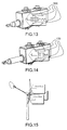
- FIG 13 and 14 is represented a second example of use of the method.
- a user or designer can for example use the invention for an hydraulic valve. It is possible, like on this example, to have ports 130 for directly linking in the scene a logical component to a corresponding three-dimensional geometrical element. In this case, the ports 130 are linked to the hydraulic circuit.
- a link can be represented by an extensible leading line.
- the logical diagram representation can be animated and synchronized with the three-dimensional representation animation.
- figure 13 represents the drawer retracted with linked three-dimensional geometrical representation and logical representation
- figure 14 represents the drawer extended with linked three-dimensional geometrical representation and logical representation.
- FIG 15 is represented a third example which is a wind turbine or aeolian well, with several logical diagrams attached to different geometrical elements can be displayed simultaneously.
- logical diagrams are displayed according to the depth position in the scene of the associated three-dimensional geometrical element or set of geometrical elements.
- the logical label corresponding to the closest set of at least one three-dimensional geometrical element in the scene is displayed on top of others one, and so on when the depth increases.
- Figure 16 shows a client computer system, for instance a workstation of a user designing an assembly of objects.
- the client computer comprises a central processing unit or CPU 160 connected to an internal communication BUS 161, a random access memory or RAM 162 also connected to the BUS 161.
- the client computer system is further provided with a graphical processing unit or GPU 163 which is associated with a video random access memory 164 connected to the communication BUS 161.
- Video RAM 164 is also known in the art as frame buffer.
- a mass storage device controller 165 manages accesses to a mass memory device, such as hard drive 166.
- Mass memory devices suitable for tangibly embodying computer program instructions and data include all forms of nonvolatile memory, including by way of example semiconductor memory devices, such as EPROM, EEPROM, and flash memory devices; magnetic disks such as internal hard disks and removable disks; magnetooptical disks; and CD-ROM disks 167. Any of the foregoing may be supplemented by, or incorporated in, specially designed ASICs (application-specific integrated circuits).
- a network adapter 168 manages accesses to a network 169.
- the client computer system may also include a haptic device 170 such as cursor control device, a keyboard or the like.
- a cursor control device is used in the client computer to permit the user to selectively position a cursor at any desired location on display 171.
- the cursor control device allows the user to select various commands, and input control signals.
- the cursor control device includes a number of signal generation devices for input control signals to system.
- a cursor control device may be a mouse, the button of the mouse being used to generate the signals.
Landscapes
- Engineering & Computer Science (AREA)
- Physics & Mathematics (AREA)
- Theoretical Computer Science (AREA)
- Geometry (AREA)
- General Physics & Mathematics (AREA)
- General Engineering & Computer Science (AREA)
- Computer Hardware Design (AREA)
- Software Systems (AREA)
- Evolutionary Computation (AREA)
- Computer Graphics (AREA)
- Mathematical Optimization (AREA)
- Pure & Applied Mathematics (AREA)
- Mathematical Analysis (AREA)
- Computational Mathematics (AREA)
- Architecture (AREA)
- Human Computer Interaction (AREA)
- Processing Or Creating Images (AREA)
Abstract
- providing (90) a three-dimensional geometrical modeled object comprising at least one three-dimensional geometrical element;
- providing (91) a logical modeled object comprising at least one logical component;
- associating (92) sets of at least one three-dimensional geometrical element with respective sets of at least one logical component;
characterized in that the method further comprises a step of displaying (93) in a three-dimensional scene, a representation of a set of at least one logical component partially superimposed on the corresponding associated set of at least one three-dimensional geometrical element.
Description
- The invention relates to the field of computers programs and systems, and more specifically to the field of designing of an assembly of object in a Computer-Aided Design application.
- Computer-aided techniques are known to include Computer-Aided Design or CAD, which relates to software solutions for authoring product design. Similarly, CAE is an acronym for Computer-Aided Engineering, e.g. it relates to software solutions for simulating the physical behavior of a future product. CAM stands for Computer-Aided Manufacturing and typically includes software solutions for defining manufacturing processes and operations.
- A number of systems and programs are offered on the market for the design of objects (or parts) or assemblies of objects, forming a product, such as the one provided by Dassault Systèmes under the trademark CATIA. These CAD systems allow a user to construct and manipulate complex three dimensional or 3D models of objects or assemblies of objects. CAD systems thus provide a representation of modeled objects using edges or lines, in certain cases with faces. Lines or edges may be represented in various manners, e.g. non-uniform rational B-splines (NURBS). These CAD systems manage parts or assemblies of parts as modeled objects, which are mostly specifications of geometry. Specifically, CAD files contain specifications, from which geometry is generated, which in turn allow for a representation to be generated. Geometry and representation may be stored in a single CAD file or multiple ones. CAD systems include graphic tools for representing the modeled objects to the designers; these tools are dedicated to the display of complex objects; the typical size of a file representing an object in a CAD system being in the range of one Megabyte per part, and an assembly may comprise thousands of parts. A CAD system manages models of objects, which are stored in electronic files.
- In computer-aided techniques, the graphical user interface GUI plays an important role as regards the efficiency of the technique. Most of the operations required for manipulating and/or navigating the modeled objects may be performed by the user (e.g. the designers) on the GUI. Especially, the user may create, modify, and delete the modeled objects forming the product, and also explore the product so as to comprehend how modeled objects are interrelated, e.g. via a product structure. Traditionally, these operations are carried out through dedicated menus and icons which are located on the sides of the GUI. Recently, CAD systems such as CATIA allow calling these operations nearby the representation of the product. The designer does not need anymore to move the mouse towards menus and icons. Operations are thus available within reach of the mouse. In addition, the operations behave semantically: for a given operation selected by the designer, the CAD system may suggest to the designer, still nearby the mouse, a set of new operations according to the former selected operation that the designer is likely to select.
- Until recent years, some computer software used, for example in automotive and aerospace industry, are based on geometry, for mechanical engineers to be able to see their work in space or in a three-dimensional displaying.
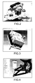
- In this domain, computer software like CATIA, SolidWorks, NX, and ProEngineer allow design geometry in a three dimension space, like respectively shown on
figures 1 ,2, 3 and 4 . On these figures, the exemplified graphical user interfaces or GUI are typical CAD-like interfaces with standard menu bars. Such menu and toolbars contain a set of user-selectable icons, each icon being associated with one or more operations or functions. Some of these icons are associated with software tools, adapted for editing and/or working on a 3D geometrical modeled product or parts of product such as that displayed in the graphical user interfaces GUI. In the following description, terms "product", "part", "assembly" and the like may be referred to as "part" for the sake of simplicity. The concept of "part" can also be generalized to that of "object". An object encompasses any constituent of the final digital mock-up, for instance, considering an assembly, an object of this assembly can be a sub-assembly, a part, a kinematic joint, a material, the embedded software executed on an Electronic Control Unit (ECU), or any object needed to describe the entire environment of the assembly, like the modeling of the atmosphere in the case you want to study an airplane flying capacities. - It is still possible to use computer software like Matlab Simulink, Dymola, and Simulation X, which provide a rich two-dimensional displaying environment to design a logical system from logical components, like respectively shown on
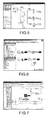
figures 5, 6 and 7 . On these figures, the exemplified graphical user interfaces or GUI have standard menu bars. Such menu and toolbars contain a set of user-selectable icons, each icon being associated with one or more operations or functions. Some of these icons are associated with software tools, adapted for editing and/or working on a logical modeled product or parts of product such as that displayed in the graphical user interfaces GUI. - In CATIA system, a set of tools provides an environment allowing to view and design in the
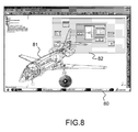
same editor 80, i.e. on the same screen displaying, a three-dimensionalgeometrical representation 81 and separately alogical representation 82. - Such displaying of the separate three-dimensional geometrical and logical representations is shown on
figure 8 . - With these kind of systems, understanding how a product or assembly of objects works is really difficult, particularly when the products becomes more and more complex, since it is difficult for a user to see how the mechanical parts interact with the system components, and what information is exchanged between geometrical representation and logical representation.
- Thus, there is no link between the used geometrical representation and logical representation.
- Thus, according to the limitations of the existing solutions shortly discussed above, there is a need for improving the recurrent assembly of objects in an easier and faster way such that the productivity of the designer is increased and the design errors minimized.
- In other words, there is a need for improving readability, allowing the user to work more efficiently.
- It is proposed, according to one aspect of the invention, a computer-implemented method of designing an assembly of objects in a system of computer-aided design, the method comprising the steps of:
- providing a three-dimensional geometrical modeled object comprising at least one three-dimensional geometrical element;
- providing a logical modeled object comprising at least one logical component;
- associating sets of at least one three-dimensional geometrical element with respective sets of at least one logical component;
wherein the method further comprises a step of displaying in a three-dimensional scene, a representation of a set of at least one logical component partially superimposed on the corresponding associated set of at least one three-dimensional geometrical element. - Making a link, both in a technical and a visual manner between the used geometrical and logical representations, allows to the user to work more efficiently, and to improve technical interactions between the technical data representative of the geometric representation and the logical representation.
- Such a method allows the user to view and design the complete system in a single three-dimensional environment mixing a three-dimensional geometry representation and a logical representation in the same editor.
- Furthermore, the method helps the user to understand the full system behavior by locating the appropriate information directly in three dimensions so that the user can easily understand and design which part of the mechanism is in interaction with the system logical definition and how they interact.
- According to an embodiment, the representation of a set of at least one logical component is designed by directly linking in the scene said representation with an anchor point to the corresponding associated set of at least one three-dimensional geometrical element.
- Thus, when the user changes the viewing angle of the three-dimensional geometric representation, the components of the logical representation remains anchored with the corresponding three-dimensional geometrical element.
- According to an embodiment, the representation of a set of at least one logical component comprising at least one port, or in other words one interface element or connector, is designed by directly linking in the scene a logical component to a corresponding three-dimensional geometrical element.
- Such a port allows to link an element of the logical component with a sub-system of the three-dimensional geometrical element, and then improves and facilitates the design of products.
- According to an embodiment, displaying a representation of a set of at least one logical component is activable, deactivable, expandable, and zoomable on request.
- Thus, the user can choose to temporarily hide elements to focus on his area of interest.
- According to an embodiment, displaying a representation of a set of at least one logical component respects the relative depth position in the scene of the corresponding associated set of at least one three-dimensional geometrical element.
- Thus, when the user changes the viewing angle of the three-dimensional geometric representation, the displaying of the corresponding components of the logical representation is automatically changed in relation to said change of viewing angle.
- In addition, a link could be represented by an extensible leading line.
- Thus it is easier to the user to understand a complex product during modifications of the viewing angle of the three-dimensional geometric representation.
- The displaying of a representation of a set of at least one logical component can be comprised in a label.
- Thus the realization and comprehension is improved.
- The invention further proposes a computer program product, stored on a computer readable medium, for designing an assembly of objects in a system of computer-aided design, the computer program comprising code means for causing the system of computer-aided design to take the steps of the method of the invention.
- The invention still concerns an apparatus for designing an assembly of objects in a system of computer-aided design, the apparatus comprising means for implementing the steps of the method of the invention.
- The invention will be better understood with the study of some embodiments described by way of non-limiting examples and illustrated by the accompanying drawings wherein :
-
figures 1 to 4 illustrate respectively the following computer software CATIA, SolidWorks, NX, and ProEngineer allowing design geometry in a three dimension space ; -
figures 5 to 7 illustrate respectively the following computer software Matlab Simulink, Dymola, and Simulation X, which provide a rich two-dimensional displaying environment to design a logical system from logical components ; -
figure 8 illustrates computer software CATIA, providing an environment allowing to view and design in the same editor, i.e. on the same screen displaying, a three-dimensional geometrical representation, and separately a logical representation ; -
figure 9 illustrates a method according to an aspect of the invention; -
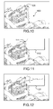
figures 10 to 12 illustrate an example of use of the method according to an aspect of the invention ; -
figures 13 and 14 illustrate another example of use of the method according to an aspect of the invention ; -
figures 15 illustrates another example of use of the method according to an aspect of the invention ; -
figure 16 illustrates a schematic view of a hardware and software environment adapted for carrying out the invention. -
Figure 9 is a flowchart depicting an embodiment of the invention wherein four blocks are to be seen, pertaining respectively to phases of providing 90 a three-dimensional geometrical modeled object comprising at least one three-dimensional geometrical element, providing 91 a logical modeled object comprising at least one logical component, associating 92 sets of at least one three-dimensional geometrical element with respective sets of at least one logical component, and displaying 93 in a three-dimensional scene, a representation of a set of at least one logical component partially superimposed on the corresponding associated set of at least one three-dimensional geometrical element. - The steps of the method described above can be performed by one or more programmable processors executing a computer program to perform functions of the invention by operating on input data and generating output.
- A computer program can be written in any form of programming language, including compiled or interpreted languages, and the computer program can be deployed in any form, including as a stand-alone program or as a subroutine, element or other unit suitable for use in a computing environment. A computer program can be deployed to be executed on one computer or on multiple computers at one site or distributed across multiple sites and interconnected by a communication network.
- Following figures explain more in details the functioning of the present invention.
- On
figure 10 to 12 is represented a first example of use of the method. A user or designer starts from a three-dimensional scene containing geometrical elements. An element is either a part of a mechanical assembly or a relation between those parts. Onfigure 10 is represented a part of amotor 100, and particularly a kinematic joint 101 between several parts that links the parts together and drive motion of the parts. - It is possible, for the designer, to start designing the logical system definition directly from this scene either by defining actuators that act on the mechanical structure and modify its position according to the values given by the logical system, and/or defining sensors that measure physical data, like speed or force, for a control loop for instance.
- To do so, the user or designer selects a three-dimensional geometrical entity, on this example a three-dimensional mechanical joint 101, and starts a command that inserts a
placeholder 110, for example a label, like illustrated onfigure 11 , to receive the set of logical components in relation with this geometrical element and that interacts with it. By default, the inserted placeholder can be almost empty and contain just a connector to hook more precisely the logical components to the geometrical element (it allows for instance to hook to a particular signal coming from, or going to the mechanical system). - The representation of a set of at least one logical component can be designed by directly linking in the scene said representation with an
anchor point 111 to the corresponding associated set of at least one three-dimensional geometrical element. Thus, when the point of view of the assembly of objects is changed by the designer, the logical label remains linked with the set of at least one three-dimensional element during the change. - It is then possible for the designer to design the logical system that is in interaction with the mechanics by putting components, for instance from a library, inside the created
empty space 110, and connecting them to the connector, like illustrated onfigure 12 , with a logical diagram in the placeholder. - Then it is really much easier to view and design a mechanical system with the invention, notably thanks to the interaction between three-dimensional geometrical elements and logical components of the mechanical system.
- On
figure 13 and 14 is represented a second example of use of the method. A user or designer can for example use the invention for an hydraulic valve. It is possible, like on this example, to haveports 130 for directly linking in the scene a logical component to a corresponding three-dimensional geometrical element. In this case, theports 130 are linked to the hydraulic circuit. - In this example, the logical description shows what flow of oil corresponds to the extracted and retracted position of the drawer.
- A link can be represented by an extensible leading line.
- Thus the logical diagram representation can be animated and synchronized with the three-dimensional representation animation.
- Indeed,
figure 13 represents the drawer retracted with linked three-dimensional geometrical representation and logical representation, andfigure 14 represents the drawer extended with linked three-dimensional geometrical representation and logical representation. - On
figure 15 , is represented a third example which is a wind turbine or aeolian well, with several logical diagrams attached to different geometrical elements can be displayed simultaneously. In that case, logical diagrams are displayed according to the depth position in the scene of the associated three-dimensional geometrical element or set of geometrical elements. The logical label corresponding to the closest set of at least one three-dimensional geometrical element in the scene is displayed on top of others one, and so on when the depth increases. -
Figure 16 shows a client computer system, for instance a workstation of a user designing an assembly of objects. The client computer comprises a central processing unit orCPU 160 connected to aninternal communication BUS 161, a random access memory orRAM 162 also connected to theBUS 161. The client computer system is further provided with a graphical processing unit orGPU 163 which is associated with a videorandom access memory 164 connected to thecommunication BUS 161.Video RAM 164 is also known in the art as frame buffer. A massstorage device controller 165 manages accesses to a mass memory device, such ashard drive 166. Mass memory devices suitable for tangibly embodying computer program instructions and data include all forms of nonvolatile memory, including by way of example semiconductor memory devices, such as EPROM, EEPROM, and flash memory devices; magnetic disks such as internal hard disks and removable disks; magnetooptical disks; and CD-ROM disks 167. Any of the foregoing may be supplemented by, or incorporated in, specially designed ASICs (application-specific integrated circuits). Anetwork adapter 168 manages accesses to anetwork 169. The client computer system may also include ahaptic device 170 such as cursor control device, a keyboard or the like. A cursor control device is used in the client computer to permit the user to selectively position a cursor at any desired location ondisplay 171. In addition, the cursor control device allows the user to select various commands, and input control signals. The cursor control device includes a number of signal generation devices for input control signals to system. Typically, a cursor control device may be a mouse, the button of the mouse being used to generate the signals. - The preferred embodiment of the present invention has been described. It will be understood that various modifications may be made without departing from the spirit and scope of the invention. Therefore, other implementations are within the scope of the following claims. For instance, the ranking of the criteria may depend on the technical context of the assembly.
Claims (9)
- A computer-implemented method of designing an assembly of objects in a system of computer-aided design, the method comprising the steps of :- providing (90) a three-dimensional geometrical modeled object comprising at least one three-dimensional geometrical element;- providing (91) a logical modeled object comprising at least one logical component;- associating (92) sets of at least one three-dimensional geometrical element with respective sets of at least one logical component;characterized in that the method further comprises a step of displaying (93) in a three-dimensional scene, a representation of a set of at least one logical component partially superimposed on the corresponding associated set of at least one three-dimensional geometrical element.
- The method of claim 1, wherein the representation of a set of at least one logical component is designed by directly linking in the scene said representation with an anchor point (111) to the corresponding associated set of at least one three-dimensional geometrical element.
- The method of claim 1 or 2, wherein the representation of a set of at least one logical component comprising at least one port (130) is designed by directly linking in the scene a logical component to a corresponding three-dimensional geometrical element.
- The method of anyone of preceding claims, wherein displaying a representation of a set of at least one logical component is activable, deactivable, expandable, and zoomable on request.
- The method of anyone of preceding claims, wherein displaying a representation of a set of at least one logical component respects the relative depth position in the scene of the corresponding associated set of at least one three-dimensional geometrical element.
- The method of anyone of preceding claims, wherein a link is represented by an extensible leading line.
- The method of anyone of preceding claims, wherein displaying a representation of a set of at least one logical component is comprised in a label (110, 120).
- A computer program product, stored on a computer readable medium, for designing an assembly of objects in a system of computer-aided design, the computer program comprising code means for causing the system of computer-aided design to take the steps of anyone of claims 1 to 7.
- An apparatus for designing an assembly of objects in a system of computer-aided design, the apparatus comprising means for implementing the steps of the method of anyone of claims 1 to 7.
Priority Applications (6)
| Application Number | Priority Date | Filing Date | Title |
|---|---|---|---|
| EP11306115A EP2568400A1 (en) | 2011-09-08 | 2011-09-08 | Method and system for designing an assembly of objects in a system of computer-aided design |
| US13/597,179 US10210304B2 (en) | 2011-09-08 | 2012-08-28 | Method and system for designing an assembly of objects in a system of computer-aided design |
| CA2788392A CA2788392C (en) | 2011-09-08 | 2012-08-31 | Method and system for designing an assembly of objects in a system of computer-aided design |
| JP2012196444A JP6157819B2 (en) | 2011-09-08 | 2012-09-06 | Method and system for designing an assembly of objects in a computer aided design system |
| KR1020120099589A KR101988663B1 (en) | 2011-09-08 | 2012-09-07 | Method and system for designing an assembly of objects in a system of computer-aided design |
| CN201210330210.8A CN102999657B (en) | 2011-09-08 | 2012-09-07 | Method and system for the design object sub-assembly in computer aided design system |
Applications Claiming Priority (1)
| Application Number | Priority Date | Filing Date | Title |
|---|---|---|---|
| EP11306115A EP2568400A1 (en) | 2011-09-08 | 2011-09-08 | Method and system for designing an assembly of objects in a system of computer-aided design |
Publications (1)
| Publication Number | Publication Date |
|---|---|
| EP2568400A1 true EP2568400A1 (en) | 2013-03-13 |
Family
ID=44772968
Family Applications (1)
| Application Number | Title | Priority Date | Filing Date |
|---|---|---|---|
| EP11306115A Ceased EP2568400A1 (en) | 2011-09-08 | 2011-09-08 | Method and system for designing an assembly of objects in a system of computer-aided design |
Country Status (6)
| Country | Link |
|---|---|
| US (1) | US10210304B2 (en) |
| EP (1) | EP2568400A1 (en) |
| JP (1) | JP6157819B2 (en) |
| KR (1) | KR101988663B1 (en) |
| CN (1) | CN102999657B (en) |
| CA (1) | CA2788392C (en) |
Families Citing this family (8)
| Publication number | Priority date | Publication date | Assignee | Title |
|---|---|---|---|---|
| US9761045B1 (en) | 2013-03-15 | 2017-09-12 | Bentley Systems, Incorporated | Dynamic and selective model clipping for enhanced augmented hypermodel visualization |
| US9460561B1 (en) | 2013-03-15 | 2016-10-04 | Bentley Systems, Incorporated | Hypermodel-based panorama augmentation |
| JP2018501532A (en) * | 2014-10-02 | 2018-01-18 | シーメンス アクチエンゲゼルシヤフトSiemens Aktiengesellschaft | Automation programming in 3D graphic editors using tightly coupled logic and physical simulation |
| US10127331B2 (en) * | 2014-12-15 | 2018-11-13 | The Boeing Company | 3D models utilizing 3D markers to indicate engineering requirements |
| FR3035983A1 (en) * | 2015-05-04 | 2016-11-11 | Airbus Helicopters | METHOD AND DEVICE FOR SELECTING AND DISPLAYING MAINTENANCE PLUGS FOR AN AIRCRAFT |
| US10416836B2 (en) * | 2016-07-11 | 2019-09-17 | The Boeing Company | Viewpoint navigation control for three-dimensional visualization using two-dimensional layouts |
| EP3484674B1 (en) * | 2016-08-17 | 2021-07-07 | Siemens Aktiengesellschaft | Method and system for preserving privacy for cloud-based manufacturing analysis services |
| EP3644198B1 (en) * | 2018-10-26 | 2024-04-17 | Dassault Systèmes | 3d design of b-rep skin |
Citations (1)
| Publication number | Priority date | Publication date | Assignee | Title |
|---|---|---|---|---|
| US20090213116A1 (en) * | 2008-02-21 | 2009-08-27 | Max Konev | Pmi data visualization |
Family Cites Families (7)
| Publication number | Priority date | Publication date | Assignee | Title |
|---|---|---|---|---|
| JPH08161388A (en) * | 1994-12-05 | 1996-06-21 | Nec Corp | Three-dimensional cad system |
| US6016147A (en) * | 1995-05-08 | 2000-01-18 | Autodesk, Inc. | Method and system for interactively determining and displaying geometric relationships between three dimensional objects based on predetermined geometric constraints and position of an input device |
| JP3933792B2 (en) | 1998-06-02 | 2007-06-20 | 三菱電機株式会社 | 3D layout design support device |
| US6665569B1 (en) * | 2000-01-12 | 2003-12-16 | Parametric Technology Corporation | Method and system for dynamically updating geometric models |
| EP1267285A3 (en) * | 2001-06-13 | 2003-02-12 | Sumitomo Wiring Systems, Ltd. | Method, computer program and system for designing a wiring harness assembling table |
| EP1672549A1 (en) | 2004-12-20 | 2006-06-21 | Dassault Systèmes | Product edition and simulation database system with user interaction graphical tool |
| CN100483343C (en) * | 2007-11-30 | 2009-04-29 | 清华大学 | Emulated procedure information modeling and maintenance method based on product structural tree |
-
2011
- 2011-09-08 EP EP11306115A patent/EP2568400A1/en not_active Ceased
-
2012
- 2012-08-28 US US13/597,179 patent/US10210304B2/en active Active
- 2012-08-31 CA CA2788392A patent/CA2788392C/en active Active
- 2012-09-06 JP JP2012196444A patent/JP6157819B2/en active Active
- 2012-09-07 CN CN201210330210.8A patent/CN102999657B/en active Active
- 2012-09-07 KR KR1020120099589A patent/KR101988663B1/en active Active
Patent Citations (1)
| Publication number | Priority date | Publication date | Assignee | Title |
|---|---|---|---|---|
| US20090213116A1 (en) * | 2008-02-21 | 2009-08-27 | Max Konev | Pmi data visualization |
Non-Patent Citations (8)
| Title |
|---|
| "Intelligent Hypertext", vol. 1326, 1 January 1997, SPRINGER-VERLAG, Berlin/Heidelberg, ISBN: 978-3-54-063637-3, article ENRICO GOBBETTI ET AL: "Exploring annotated 3D environments on the World Wide Web", pages: 31 - 46, XP055030228 * |
| ASHLAR VELLUM: "Cobalt Xenon Argon Designer elements 3D Modeling User Guide - Excerpt: Parametric Constraints", INTERNET CITATION, 1 January 2003 (2003-01-01), pages 38.5 - 38.20, XP007906865, Retrieved from the Internet <URL:http://www.ashlar.com/support/3d_modeling_gs_v6.pfd> [retrieved on 20090120] * |
| JASON WITHER ET AL: "Using aerial photographs for improved mobile AR annotation", MIXED AND AUGMENTED REALITY, 2006. ISMAR 2006. IEEE/ACM INTERNATIONAL SYMPOSIUM ON, IEEE, PI, 1 October 2006 (2006-10-01), pages 159 - 162, XP031014664, ISBN: 978-1-4244-0650-0 * |
| K GÖTZELMANN ET AL: "Form follows function: Aesthetic interactive labels", COMPUTATIONAL AESTHETICS IN GRAPHICS, VISUALIZATION AND IMAGING (2005), 1 January 2005 (2005-01-01), pages 1 - 8, XP055018377, Retrieved from the Internet <URL:http://www.medvis-book.de/MedVisBookMaterial/Chapter20/ca05.pdf#4> [retrieved on 20120203] * |
| KAVEH BAZARGAN ET AL: "Specifying the Representation of Non-geometric Information in 3D Virtual Environments", 19 July 2009, HUMAN-COMPUTER INTERACTION. NOVEL INTERACTION METHODS AND TECHNIQUES, SPRINGER BERLIN HEIDELBERG, BERLIN, HEIDELBERG, PAGE(S) 773 - 782, ISBN: 978-3-642-02576-1, XP019122181 * |
| SOHRT W ET AL: "Interaction with constraints in 3D modeling", PROCEEDINGS. SYMPOSIUM ON SOLID MODELING FOUNDATIONS AND CAD /CAM APPLICATIONS, XX, XX, 5 June 1991 (1991-06-05), pages 387 - 396, XP002231158, DOI: 10.1145/112515.112570 * |
| SUTHERLAND I E ED - AMERICAN FEDERATION OF INFORMATION PROCESSING SOCIETIES: "SKETCHPAD A MAN-MACHINE GRAPHICAL COMMUNICATION SYSTEM", PROCEEDINGS OF THE SPRING JOINT COMPUTER CONFERENCE. DETROIT, MAY, 1963; [JOINT COMPUTER CONFERENCE], BALTIMORE, SPARTAN BOOKS, US, vol. 1963 VOL. 23, 1 May 1963 (1963-05-01), pages 329 - 346, XP009032646 * |
| THIERRY STEIN ET AL: "Dynamic label placement for improved interactive exploration", PROCEEDINGS OF THE 6TH INTERNATIONAL SYMPOSIUM ON NON-PHOTOREALISTIC ANIMATION AND RENDERING , NPAR '08, 1 January 2008 (2008-01-01), New York, New York, USA, pages 15, XP055018365, ISBN: 978-1-60-558150-7, DOI: 10.1145/1377980.1377986 * |
Also Published As
| Publication number | Publication date |
|---|---|
| US10210304B2 (en) | 2019-02-19 |
| JP6157819B2 (en) | 2017-07-05 |
| CA2788392C (en) | 2019-10-01 |
| US20130226529A1 (en) | 2013-08-29 |
| CA2788392A1 (en) | 2013-03-08 |
| KR101988663B1 (en) | 2019-06-12 |
| CN102999657A (en) | 2013-03-27 |
| KR20130028021A (en) | 2013-03-18 |
| CN102999657B (en) | 2018-01-23 |
| JP2013058201A (en) | 2013-03-28 |
Similar Documents
| Publication | Publication Date | Title |
|---|---|---|
| US10210304B2 (en) | Method and system for designing an assembly of objects in a system of computer-aided design | |
| US8749588B2 (en) | Positioning labels in an engineering drawing | |
| EP3040945B1 (en) | Creation of bounding boxes on a 3d modeled assembly | |
| US10152198B2 (en) | Method and system for editing a product assembly | |
| US8907947B2 (en) | Method and system for navigating in a product structure of a product | |
| CA2776638C (en) | Designing a three-dimensional modeled assembly of objects in a three-dimensional scene | |
| US20120287121A1 (en) | Method for designing a geometrical three-dimensional modeled object | |
| US10474763B2 (en) | Computer-implemented method for defining initial conditions for dynamic simulation of an assembly of objects in a three-dimensional scene of a system of computer-aided design | |
| CN105760570A (en) | Viewpoint selection in the redering of a set of objects | |
| EP4195014A1 (en) | Multi-render user interface | |
| US20100262930A1 (en) | Method, Program and Product Edition System for Visualizing Objects Displayed on a Computer Screen | |
| EP2911072A1 (en) | Designing a physical system constrained by equations | |
| US9223488B1 (en) | Navigable interfaces for graphical representations | |
| EP3037944B1 (en) | Designing a multi-physics system | |
| EP2523131A1 (en) | Designing a staggered pattern of objects in a computer-aided design system | |
| JP2022019615A (en) | Method for designing three-dimensional mesh in 3d scene | |
| CA2795855C (en) | Method and system for designing a modeled assembly of at least one object in a computer-aided design system | |
| EP4675411A1 (en) | Annotating a 3d modeled object representing a cad mechanical part or assembly of parts | |
| JP4786486B2 (en) | Information processing apparatus, information processing apparatus control method, and program | |
| US9092584B2 (en) | Method and system for designing a modeled assembly of at least one object in a computer-aided design system |
Legal Events
| Date | Code | Title | Description |
|---|---|---|---|
| PUAI | Public reference made under article 153(3) epc to a published international application that has entered the european phase |
Free format text: ORIGINAL CODE: 0009012 |
|
| AK | Designated contracting states |
Kind code of ref document: A1 Designated state(s): AL AT BE BG CH CY CZ DE DK EE ES FI FR GB GR HR HU IE IS IT LI LT LU LV MC MK MT NL NO PL PT RO RS SE SI SK SM TR |
|
| AX | Request for extension of the european patent |
Extension state: BA ME |
|
| 17P | Request for examination filed |
Effective date: 20130903 |
|
| RBV | Designated contracting states (corrected) |
Designated state(s): AL AT BE BG CH CY CZ DE DK EE ES FI FR GB GR HR HU IE IS IT LI LT LU LV MC MK MT NL NO PL PT RO RS SE SI SK SM TR |
|
| STAA | Information on the status of an ep patent application or granted ep patent |
Free format text: STATUS: EXAMINATION IS IN PROGRESS |
|
| 17Q | First examination report despatched |
Effective date: 20170905 |
|
| APBK | Appeal reference recorded |
Free format text: ORIGINAL CODE: EPIDOSNREFNE |
|
| APBN | Date of receipt of notice of appeal recorded |
Free format text: ORIGINAL CODE: EPIDOSNNOA2E |
|
| APBR | Date of receipt of statement of grounds of appeal recorded |
Free format text: ORIGINAL CODE: EPIDOSNNOA3E |
|
| APAV | Appeal reference deleted |
Free format text: ORIGINAL CODE: EPIDOSDREFNE |
|
| APBT | Appeal procedure closed |
Free format text: ORIGINAL CODE: EPIDOSNNOA9E |
|
| STAA | Information on the status of an ep patent application or granted ep patent |
Free format text: STATUS: THE APPLICATION HAS BEEN REFUSED |
|
| 18R | Application refused |
Effective date: 20230531 |