EP2568274A1 - Photoacoustic matching material - Google Patents
Photoacoustic matching material Download PDFInfo
- Publication number
- EP2568274A1 EP2568274A1 EP12005925A EP12005925A EP2568274A1 EP 2568274 A1 EP2568274 A1 EP 2568274A1 EP 12005925 A EP12005925 A EP 12005925A EP 12005925 A EP12005925 A EP 12005925A EP 2568274 A1 EP2568274 A1 EP 2568274A1
- Authority
- EP
- European Patent Office
- Prior art keywords
- matching material
- photoacoustic
- photoacoustic matching
- light
- resins
- Prior art date
- Legal status (The legal status is an assumption and is not a legal conclusion. Google has not performed a legal analysis and makes no representation as to the accuracy of the status listed.)
- Granted
Links
- 239000000463 material Substances 0.000 title claims abstract description 100
- 238000000149 argon plasma sintering Methods 0.000 claims abstract description 38
- XLYOFNOQVPJJNP-UHFFFAOYSA-N water Substances O XLYOFNOQVPJJNP-UHFFFAOYSA-N 0.000 claims abstract description 13
- 239000002562 thickening agent Substances 0.000 claims abstract description 11
- 229920005989 resin Polymers 0.000 claims description 11
- 239000011347 resin Substances 0.000 claims description 11
- 230000031700 light absorption Effects 0.000 claims description 8
- GWEVSGVZZGPLCZ-UHFFFAOYSA-N Titan oxide Chemical compound O=[Ti]=O GWEVSGVZZGPLCZ-UHFFFAOYSA-N 0.000 claims description 7
- VYPSYNLAJGMNEJ-UHFFFAOYSA-N Silicium dioxide Chemical compound O=[Si]=O VYPSYNLAJGMNEJ-UHFFFAOYSA-N 0.000 claims description 6
- 239000006229 carbon black Substances 0.000 claims description 5
- OGIDPMRJRNCKJF-UHFFFAOYSA-N titanium oxide Inorganic materials [Ti]=O OGIDPMRJRNCKJF-UHFFFAOYSA-N 0.000 claims description 5
- PAYRUJLWNCNPSJ-UHFFFAOYSA-N Aniline Chemical compound NC1=CC=CC=C1 PAYRUJLWNCNPSJ-UHFFFAOYSA-N 0.000 claims description 4
- XLOMVQKBTHCTTD-UHFFFAOYSA-N Zinc monoxide Chemical compound [Zn]=O XLOMVQKBTHCTTD-UHFFFAOYSA-N 0.000 claims description 4
- MCMNRKCIXSYSNV-UHFFFAOYSA-N Zirconium dioxide Chemical compound O=[Zr]=O MCMNRKCIXSYSNV-UHFFFAOYSA-N 0.000 claims description 4
- 229910010272 inorganic material Inorganic materials 0.000 claims description 4
- 239000011147 inorganic material Substances 0.000 claims description 4
- 239000000203 mixture Substances 0.000 claims description 4
- 239000011368 organic material Substances 0.000 claims description 3
- 239000002245 particle Substances 0.000 claims description 3
- GZVHEAJQGPRDLQ-UHFFFAOYSA-N 6-phenyl-1,3,5-triazine-2,4-diamine Chemical compound NC1=NC(N)=NC(C=2C=CC=CC=2)=N1 GZVHEAJQGPRDLQ-UHFFFAOYSA-N 0.000 claims description 2
- 229920002134 Carboxymethyl cellulose Polymers 0.000 claims description 2
- YCKRFDGAMUMZLT-UHFFFAOYSA-N Fluorine atom Chemical compound [F] YCKRFDGAMUMZLT-UHFFFAOYSA-N 0.000 claims description 2
- 239000005909 Kieselgur Substances 0.000 claims description 2
- 229920000877 Melamine resin Polymers 0.000 claims description 2
- 239000004952 Polyamide Substances 0.000 claims description 2
- 239000004642 Polyimide Substances 0.000 claims description 2
- BQCADISMDOOEFD-UHFFFAOYSA-N Silver Chemical compound [Ag] BQCADISMDOOEFD-UHFFFAOYSA-N 0.000 claims description 2
- 229920002125 Sokalan® Polymers 0.000 claims description 2
- 229920001807 Urea-formaldehyde Polymers 0.000 claims description 2
- PNEYBMLMFCGWSK-UHFFFAOYSA-N aluminium oxide Inorganic materials [O-2].[O-2].[O-2].[Al+3].[Al+3] PNEYBMLMFCGWSK-UHFFFAOYSA-N 0.000 claims description 2
- BRPQOXSCLDDYGP-UHFFFAOYSA-N calcium oxide Chemical compound [O-2].[Ca+2] BRPQOXSCLDDYGP-UHFFFAOYSA-N 0.000 claims description 2
- 239000000292 calcium oxide Substances 0.000 claims description 2
- ODINCKMPIJJUCX-UHFFFAOYSA-N calcium oxide Inorganic materials [Ca]=O ODINCKMPIJJUCX-UHFFFAOYSA-N 0.000 claims description 2
- 239000001768 carboxy methyl cellulose Substances 0.000 claims description 2
- 235000010948 carboxy methyl cellulose Nutrition 0.000 claims description 2
- 239000008112 carboxymethyl-cellulose Substances 0.000 claims description 2
- 239000001913 cellulose Substances 0.000 claims description 2
- 229920002678 cellulose Polymers 0.000 claims description 2
- 239000003795 chemical substances by application Substances 0.000 claims description 2
- 229920001577 copolymer Polymers 0.000 claims description 2
- 239000003822 epoxy resin Substances 0.000 claims description 2
- 150000002148 esters Chemical class 0.000 claims description 2
- 239000011737 fluorine Substances 0.000 claims description 2
- 229910052731 fluorine Inorganic materials 0.000 claims description 2
- PCHJSUWPFVWCPO-UHFFFAOYSA-N gold Chemical compound [Au] PCHJSUWPFVWCPO-UHFFFAOYSA-N 0.000 claims description 2
- 239000010931 gold Substances 0.000 claims description 2
- 229910052737 gold Inorganic materials 0.000 claims description 2
- LNEPOXFFQSENCJ-UHFFFAOYSA-N haloperidol Chemical compound C1CC(O)(C=2C=CC(Cl)=CC=2)CCN1CCCC(=O)C1=CC=C(F)C=C1 LNEPOXFFQSENCJ-UHFFFAOYSA-N 0.000 claims description 2
- 239000000395 magnesium oxide Substances 0.000 claims description 2
- CPLXHLVBOLITMK-UHFFFAOYSA-N magnesium oxide Inorganic materials [Mg]=O CPLXHLVBOLITMK-UHFFFAOYSA-N 0.000 claims description 2
- AXZKOIWUVFPNLO-UHFFFAOYSA-N magnesium;oxygen(2-) Chemical compound [O-2].[Mg+2] AXZKOIWUVFPNLO-UHFFFAOYSA-N 0.000 claims description 2
- 239000005011 phenolic resin Substances 0.000 claims description 2
- 229920002647 polyamide Polymers 0.000 claims description 2
- 229920000515 polycarbonate Polymers 0.000 claims description 2
- 239000004417 polycarbonate Substances 0.000 claims description 2
- 229920000647 polyepoxide Polymers 0.000 claims description 2
- 229920001721 polyimide Polymers 0.000 claims description 2
- 239000003755 preservative agent Substances 0.000 claims description 2
- 239000000377 silicon dioxide Substances 0.000 claims description 2
- 229920002050 silicone resin Polymers 0.000 claims description 2
- 229910052709 silver Inorganic materials 0.000 claims description 2
- 239000004332 silver Substances 0.000 claims description 2
- MXNUCYGENRZCBO-UHFFFAOYSA-M sodium;ethene;2-methylprop-2-enoate Chemical compound [Na+].C=C.CC(=C)C([O-])=O MXNUCYGENRZCBO-UHFFFAOYSA-M 0.000 claims description 2
- 229920002803 thermoplastic polyurethane Polymers 0.000 claims description 2
- 125000000391 vinyl group Chemical group [H]C([*])=C([H])[H] 0.000 claims description 2
- 229920002554 vinyl polymer Polymers 0.000 claims description 2
- 239000000230 xanthan gum Substances 0.000 claims description 2
- 229920001285 xanthan gum Polymers 0.000 claims description 2
- 229940082509 xanthan gum Drugs 0.000 claims description 2
- 235000010493 xanthan gum Nutrition 0.000 claims description 2
- 239000011787 zinc oxide Substances 0.000 claims description 2
- 239000003002 pH adjusting agent Substances 0.000 claims 1
- 230000002335 preservative effect Effects 0.000 claims 1
- 238000003325 tomography Methods 0.000 description 21
- 210000001525 retina Anatomy 0.000 description 13
- 238000010521 absorption reaction Methods 0.000 description 10
- 239000000523 sample Substances 0.000 description 9
- 238000013016 damping Methods 0.000 description 8
- 239000006096 absorbing agent Substances 0.000 description 7
- 230000035807 sensation Effects 0.000 description 6
- 239000010419 fine particle Substances 0.000 description 5
- 230000006870 function Effects 0.000 description 4
- HEMHJVSKTPXQMS-UHFFFAOYSA-M Sodium hydroxide Chemical compound [OH-].[Na+] HEMHJVSKTPXQMS-UHFFFAOYSA-M 0.000 description 3
- 230000002238 attenuated effect Effects 0.000 description 3
- 239000000835 fiber Substances 0.000 description 3
- 230000001678 irradiating effect Effects 0.000 description 3
- 230000003287 optical effect Effects 0.000 description 3
- OKTJSMMVPCPJKN-UHFFFAOYSA-N Carbon Chemical compound [C] OKTJSMMVPCPJKN-UHFFFAOYSA-N 0.000 description 2
- PEDCQBHIVMGVHV-UHFFFAOYSA-N Glycerine Chemical compound OCC(O)CO PEDCQBHIVMGVHV-UHFFFAOYSA-N 0.000 description 2
- 238000006243 chemical reaction Methods 0.000 description 2
- 238000005516 engineering process Methods 0.000 description 2
- MOFVSTNWEDAEEK-UHFFFAOYSA-M indocyanine green Chemical compound [Na+].[O-]S(=O)(=O)CCCCN1C2=CC=C3C=CC=CC3=C2C(C)(C)C1=CC=CC=CC=CC1=[N+](CCCCS([O-])(=O)=O)C2=CC=C(C=CC=C3)C3=C2C1(C)C MOFVSTNWEDAEEK-UHFFFAOYSA-M 0.000 description 2
- 229960004657 indocyanine green Drugs 0.000 description 2
- 239000000049 pigment Substances 0.000 description 2
- 230000008707 rearrangement Effects 0.000 description 2
- RBTBFTRPCNLSDE-UHFFFAOYSA-N 3,7-bis(dimethylamino)phenothiazin-5-ium Chemical compound C1=CC(N(C)C)=CC2=[S+]C3=CC(N(C)C)=CC=C3N=C21 RBTBFTRPCNLSDE-UHFFFAOYSA-N 0.000 description 1
- 238000002835 absorbance Methods 0.000 description 1
- 230000005540 biological transmission Effects 0.000 description 1
- 229910052799 carbon Inorganic materials 0.000 description 1
- 230000008859 change Effects 0.000 description 1
- 238000003745 diagnosis Methods 0.000 description 1
- 239000000975 dye Substances 0.000 description 1
- 230000000694 effects Effects 0.000 description 1
- 235000011187 glycerol Nutrition 0.000 description 1
- 229910002804 graphite Inorganic materials 0.000 description 1
- 239000010439 graphite Substances 0.000 description 1
- 238000003384 imaging method Methods 0.000 description 1
- 230000006872 improvement Effects 0.000 description 1
- 239000010954 inorganic particle Substances 0.000 description 1
- 229910052751 metal Inorganic materials 0.000 description 1
- 239000002184 metal Substances 0.000 description 1
- 238000000034 method Methods 0.000 description 1
- 229960000907 methylthioninium chloride Drugs 0.000 description 1
- 238000012986 modification Methods 0.000 description 1
- 230000004048 modification Effects 0.000 description 1
- 230000009965 odorless effect Effects 0.000 description 1
- -1 para-hydroxybenzoate ester Chemical class 0.000 description 1
- 238000010895 photoacoustic effect Methods 0.000 description 1
- 230000000644 propagated effect Effects 0.000 description 1
- 239000000126 substance Substances 0.000 description 1
Images

Classifications
-
- G—PHYSICS
- G01—MEASURING; TESTING
- G01N—INVESTIGATING OR ANALYSING MATERIALS BY DETERMINING THEIR CHEMICAL OR PHYSICAL PROPERTIES
- G01N21/00—Investigating or analysing materials by the use of optical means, i.e. using sub-millimetre waves, infrared, visible or ultraviolet light
- G01N21/17—Systems in which incident light is modified in accordance with the properties of the material investigated
- G01N21/1702—Systems in which incident light is modified in accordance with the properties of the material investigated with opto-acoustic detection, e.g. for gases or analysing solids
-
- A—HUMAN NECESSITIES
- A61—MEDICAL OR VETERINARY SCIENCE; HYGIENE
- A61B—DIAGNOSIS; SURGERY; IDENTIFICATION
- A61B5/00—Measuring for diagnostic purposes; Identification of persons
- A61B5/0093—Detecting, measuring or recording by applying one single type of energy and measuring its conversion into another type of energy
- A61B5/0095—Detecting, measuring or recording by applying one single type of energy and measuring its conversion into another type of energy by applying light and detecting acoustic waves, i.e. photoacoustic measurements
Definitions
- One disclosed aspect of the embodiments relates to a photoacoustic matching material used for a photoacoustic tomography apparatus and the like.
- a photoacoustic tomography (PAT) apparatus used for medical diagnosis has been offered as an apparatus for imaging an inside of an object to be examined (test object) by using ultrasonic wave (acoustic wave).
- the photoacoustic tomography apparatus irradiates the test object with laser pulse light, receives photoacoustic waves resulted from absorption of energy of radiated light in tissue of the test object with a receiving element (electromechanical conversion element such as piezoelement) provided in a probe, and makes an image of information that is relevant to optical property values in the inside of the test object.
- Japanese Patent Application Laid-Open No. 2010-075681 discusses a constitution of a photoacoustic tomography apparatus in which a photoacoustic matching material is provided between a receiving element and a test object.
- a matching of a photoacoustic impedance between the test object and the probe is formed by providing the photoacoustic matching material between the test object and the receiving element in technology described in Japanese Patent Application Laid-Open No. 2010-075681 , but further improvement of the photoacoustic matching material is required. Specifically, it is required for the photoacoustic matching material that not only the photoacoustic impedance is considered but also optical properties such as reflection and transmission for the light irradiating the test object are considered. Further, good tactual sensation for the test object is also desired for the photoacoustic matching material because of being often used in direct contact with the test object such as a human body.
- a photoacoustic matching material of one embodiment is characterized by including water, a thickener, and a light scattering member.
- the photoacoustic matching material of an embodiment is also characterized by having water as a major component among the water, the thickener, and the light scattering member.
- the present invention in its first aspect provides a photoacoustic matching material as specified in claims 1 to 14.
- the photoacoustic matching material not only having a good acoustic impedance property but also having good optical properties for the light radiating to the test object. Further, it is possible to provide the photoacoustic matching material having the good tactual sensation for the test object.
- Fig. 1 is a view illustrating a photoacoustic tomography apparatus according to an embodiment.
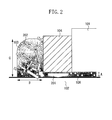
- Fig. 2 is a partially magnified view illustrating the photoacoustic tomography apparatus according to the embodiment.
- the photoacoustic tomography apparatus used in the present embodiment is an apparatus utilizing a photoacoustic effect that an acoustic wave generated by irradiating a test object with light (electromagnetic wave) is received and the information of the test object is acquired as image data.
- the acoustic wave is typically the ultrasonic wave and includes those elastic waves referred to as sound waves, ultrasonic waves, photoacoustic waves, and photo-ultrasonic waves.
- the photoacoustic tomography apparatus includes a light source not shown in the figure, a bundle fiber 105, a light irradiation unit 104, a photoacoustic matching material 103, a probe 101, a signal processing unit not shown in the figure, and a display unit not shown in the figure.
- the photoacoustic matching material includes a light scattering body 106 that is dispersed irregularly in the material and is a light scattering member, and is applied onto a surface of the test object.
- the probe 101 receives the acoustic wave from the test object 102 through the acoustic matching material 103.
- the photoacoustic tomography apparatus generates pulse light from the light source not shown in the figure, and irradiates the test object 102 with the pulse light from the light irradiation unit 104 through the bundle fiber 105 and the photoacoustic matching material 103.
- An absorber in the test object 102 generates the photoacoustic wave by the pulse light radiated into the test object 102.
- the photoacoustic wave passes through the photoacoustic matching material 103 and is received by the probe 101.
- the probe 101 and the subsequent signal processing unit convert a photoacoustic signal to an electric signal, amplify the signal, and perform delay processing and rearrangement to prepare an absorption coefficient distribution in the test object 102. For example, back projection in a time domain or Fourier domain typically used for tomography technology may be utilized as a method of rearrangement. Subsequently, the display unit displays the prepared absorption coefficient distribution.
- the light irradiation unit 104 radiates the pulse light that is output from the light source and passes through the bundle fiber 105.
- the light to be radiated is near-infrared light with wavelength of about 750 to 1100 nm.
- the light emitted from the light irradiation unit 104 enters the test object 102 through the photoacoustic matching material 103.
- the light irradiation unit 104 comes into contact with a side face of the probe 101 in Fig. 1 , but the light irradiation unit 104 may be in no contact with the probe 101, and they may be arranged with some angle.
- the photoacoustic matching material 103 is applied onto the surface of the test object.
- the light irradiation unit 104 irradiates the test object 102 with the light and the probe 101 acquires the acoustic wave from the test object 102, through the photoacoustic matching material 103.
- a thickness of the photoacoustic matching material 103 between the light irradiation unit 104 and the test object is typically about 0.5 mm or less because the light irradiation unit 104 often emits the light with being pressed to the test object 102.
- the light irradiation unit 104 is pressed after the photoacoustic matching material is applied onto the surface of the test object, and the photoacoustic matching material 103 around the light irradiation unit is applied in a size of about 10 mm from the periphery of the light irradiation unit.
- a positional relation of the light irradiation unit 104, the photoacoustic matching material 103, and the test object 102 is shown in Fig. 2 .
- the size of this photoacoustic matching material corresponds to a distance B in Fig. 2 .
- the photoacoustic matching material in the present embodiment includes water, a thickener, and a light scattering member.
- the light 201 entered from the light irradiation unit 104 partially exits outside from the photoacoustic matching material 103, but the light is scattered by the light scattering body 106 that is the light scattering member in the photoacoustic matching material 103, and thus its energy density is reduced. This further enhances the safety for an operator and the subject. This will be described in detail.
- the photoacoustic tomography apparatus generally uses laser as the light source for irradiating the test object with the light.
- JIS C6802 is provided as a rule for handling the device using the laser.
- maximum permissible exposure (MPE) for retina and MPE for skin are defined as permissible safe levels when the eye and the skin are irradiated with the laser light.
- MPE maximum permissible exposure
- the laser having the energy density equal to or less than MPE for the skin is necessary to be used in the laser device used for the photoacoustic tomography apparatus.
- the MPE for the retina is much smaller than the MPE for the skin.
- the energy density of the light leaked from the photoacoustic matching material potentially exceeds the MPE for the retina.
- the energy density of the light is sufficiently reduced by the light scattering body 106, i.e., the photoacoustic matching material itself may reduce the energy density of the light.
- the safety for the operator and the subject may further be enhanced without giving an additional contrivance to the photoacoustic tomography apparatus.
- the photoacoustic matching material in the present embodiment includes the water as the major component among the water, the thickener, and the light scattering member. This enables the photoacoustic matching material to be used without unpleasant sensation in terms of tactile sensation and odor even if the photoacoustic matching material is come into direct contact with the test object, particularly a human body.
- the photoacoustic matching material 103 is further described below.
- Carboxyvinyl polymers, carboxymethylcellulose, acrylate methyl ester copolymers, xanthan gum, and the like may be used as the thickener of the photoacoustic matching material 103.
- the photoacoustic matching material 103 may contain compositions such as moisture-holding agents, preservatives, and pH adjusters in addition to the water, the thickener, and the light scattering body 106 that is the light scattering member.
- glycerine, para-hydroxybenzoate ester, and sodium hydroxide may be contained.
- a particle diameter of the light scattering body 106 to be added may be approximately equivalent to or less than a wavelength of the light to be radiated, and may be 1 nm or more and 3 ⁇ m or less in average.
- Inorganic fine particles and organic fine particles may be used for the light scattering body 106.
- inorganic fine particle examples include inorganic particles such as silica, diatomaceous earth, alumina, zinc oxide, titania (titanium oxide), zirconia, calcium oxide, magnesium oxide, gold, silver.
- organic fine particle examples include publicly known organic resin fine particles such as vinyl resins, urethane resins, epoxy resins, ester resins, polyamide, polyimide, silicone resins, fluorine resins, phenol resins, melamine resins, benzoguanamine-based resins, urea resins, aniline resins, ionomer resins, polycarbonate, cellulose, and mixtures thereof.
- organic resin fine particles such as vinyl resins, urethane resins, epoxy resins, ester resins, polyamide, polyimide, silicone resins, fluorine resins, phenol resins, melamine resins, benzoguanamine-based resins, urea resins, aniline resins, ionomer resins, polycarbonate, cellulose, and mixtures thereof.
- Inorganic materials and organic materials may be used without limiting to either ones alone and may be combined in the light scattering body 106 to be added to the photoacoustic matching material 103.
- the photoacoustic matching material 103 When the photoacoustic matching material 103 has an absorbance for the radiated wavelength or a light absorber is added to the photoacoustic matching material 103, the entered light exits with scattering and with the light intensity attenuating.
- the light absorber to be added to the photoacoustic matching material 103 includes pigments and dyes such as methylene blue and indocyanine green (ICG).
- the light absorber and the light scattering body may be the same substance, which includes carbon black, graphite, carbon pigments, and mixed atomic valence metal complexes that absorb the near-infrared light.
- a degree of the scattering of the light that exits from the photoacoustic matching material 103 is determined by a distance where the light is propagated in the photoacoustic matching material 103 and a light-scattering coefficient.
- the light-scattering coefficient varies depending on a size, a refractive index, and a concentration of the light scattering body.
- a thickness (A in Fig. 2 ) of the photoacoustic matching material 103 between the light irradiation unit 104 and the test object is about 0.5 mm
- a scattering coefficient of the light which passes through the distance to perform isotropic scattering is 2/mm.
- the photoacoustic matching material 103 around the light irradiation unit 104 has a size of about 10 mm (B in Fig. 2 ) and a thickness of about 1 mm (C in Fig. 2 )
- the light incident from the light irradiation unit 104 to exit from the photoacoustic matching material 103 passes through a distance of about 1 mm to 10 mm.
- the scattering coefficient, when the isotropic scattering is performed on the light that passes through 10 mm, is 0.1/mm. Further the scattering coefficient, when the isotropic scattering is performed on the light that passes through 1 mm, is 1/mm. Generally, it is useful that the light (light that passes the distance A in Fig. 2 ) emitted from the photoacoustic matching material 103 toward the test object 102 is straight ahead light, and it is useful that the isotropic scattering is sufficiently performed on the light (the light that passes the distances B and C in Fig. 2 )emitted towards directions other than the test object 102 . Thus, the scatter coefficient may be advantageously 0.1/mm or more and 2.0/mm or less, and more advantageously 1.0/mm or more and 2.0/mm or less.
- the photoacoustic matching material 103 When the photoacoustic matching material 103 has an absorption coefficient, the light emitted from the photoacoustic matching material 103 is attenuated in relation to a distance where the light migrates in the photoacoustic matching material 103 and a size of the absorption coefficient. The larger the scattering coefficient is, the distance where the light migrates in the photoacoustic matching material 103 is more increased.
- the attenuation of the light from the photoacoustic matching material 103 is represented by a value of an damping coefficient calculated from the light scattering coefficient and the light absorption coefficient (equation 1).
- ⁇ eff 3 ⁇ ⁇ a ⁇ ⁇ a + ⁇ s ⁇ ⁇
- damping coefficient, the absorption coefficient, and the scattering coefficient are represented by ⁇ eff, ⁇ a, and ⁇ s', respectively.
- the light emitted from the photoacoustic matching material 103 toward the test object 102 is not so attenuated whereas the light emitted toward the direction other than the test object 102 is strongly attenuated down to approximately MPE for the retina. This is because the difference between the MPE for the retina and the MPE for the skin ranges from several to several hundred thousand times.
- the test object 102 is irradiated with the light based on the MPE for the skin because it is desirable to obtain the large signal from the test object 102.
- the MPE for the skin is 313 (J/m 2 ).
- the MPE for the retina is not determined uniquely. The reason for it is that the MPE for the retina varies depending on a range of a diffused light source and a distance to the subject. The MPE for the retina becomes high when the diffused light source is small and the operator and the subject are away from the diffused light source.
- the MPE is 0.14 (J/m 2 )
- the MPE is 0.39 (J/m 2 )
- an upper limit of the MPE is set to be 2.8 (J/m 2 ).
- the MPE for the retina is 0.14 (J/m 2 ) to 2.8 (J/m 2 ) in the photoacoustic tomography apparatus under a circumstance generally employed.
- the MPE for the retina may be set in more detail depending on statuses of use of the photoacoustic tomography apparatus, e.g., the size of the diffused light source and the distance between the diffused light source and the subject.
- the advantageous range of the damping coefficient (0.47/mm to 0.77/mm) and the absorption coefficient (0.036/mm to 0.40/mm) of the photoacoustic matching material 103 are determined by the MPE for the retina.
- the scattering coefficient, the absorption coefficient and the damping coefficient of the photoacoustic matching material 103 are appropriately set in suitable ranges depending on the wavelength used in the photoacoustic apparatus, the size of the diffused light source (surface range of photoacoustic matching material 103) for the subject, and a predicted value of the distance.
- a photoacoustic matching material and a photoacoustic tomography apparatus using the same in the present exemplary embodiment are shown in Fig. 1 .
- a photoacoustic matching material 103 is used between a light irradiation unit 104 and a test object 102 in the photoacoustic tomography apparatus.
- a laser pulse light source having a wavelength of 797 nm, a pulse width of 10 ns, and a light emission frequency of 10 Hz is used as a light source in the present exemplary embodiment.
- Ultrasonic gel (LOGICLEAN, GE Yokokawa Medical) is used as a base material of the photoacoustic matching material 103.
- the ultrasonic gel includes water and a thickener, and its major component is the water. Thus, it is odorless and non-sticky, and no unpleasant sensation is given even when the gel is used with coming into direct contact with the test object.
- Titanium oxide having a particle diameter of 0.21 ⁇ m in an amount of 0.3% by weight as the light scattering body 106 that is the light scattering member is added to and dispersed in the ultrasonic gel.
- the scattering coefficient, the absorption coefficient, and the damping coefficient are 1.0 (/mm), 0.0081 (/mm), and 0.16 (/mm), respectively. Also after adding the light scattering body 106 that is the light scattering member, no large change is found in odor and tactile sensation.
- a case is supposed in which the operator and the subject observes the diffused light source (photoacoustic matching material) on the surface of the test object at a position 1 m apart from it with an angle of 45 degrees.
- the diffused light source is supposed to be the light leaked from between the light irradiation unit 104 and the test object (A in Fig. 2 ), and its size is supposed to be 0.5 mm.
- the photoacoustic matching material 103 has a size of 10 mm (B in Fig. 2 ), and is applied in a thickness of about 10 mm (C in Fig. 2 )at the periphery of the light irradiation unit.
- a case of using the photoacoustic matching material 103 without containing the light scattering body 106 and a case of using the photoacoustic matching material 103 of the present exemplary embodiment are compared and examined.
- the energy density of the light in the case of using the photoacoustic matching material 103 of the first exemplary embodiment is about 0.007 times compared with the case of using the photoacoustic matching material without containing the light scattering body 106.
- an energy irradiation of the irradiated light is reduced from 313 (J/m 2 ) to 2.3 (J/m 2 ), and the safety for the operator and the subject may be further enhanced.
- a second exemplary embodiment will be described.
- the photoacoustic matching material 103 obtained by adding titanium oxide that is the light scattering body 106 to the ultrasonic gel containing the water as the major component and further containing the thickener was described in the first exemplary embodiment.
- the photoacoustic matching material 103 obtained by adding not only the light scattering body 106 but also a light absorber that is light absorption member will be described in the present exemplary embodiment.
- the photoacoustic matching material 103 and the photoacoustic tomography apparatus using the same in the present exemplary embodiment are shown in Fig. 2 .
- carbon black that is the light scattering body 106 as well as the absorber that is the light absorption member is added in an amount of 0.01% by weight to the photoacoustic matching material 103.
- the scattering coefficient, the damping coefficient, and the attenuation coefficient are 1.0 (/mm), 0.133 (/mm), and 0.67 (/mm), respectively.
- the absorber By adding the absorber, the energy density of the light that exited from the photoacoustic matching material 103 may be reduced compared with the first exemplary embodiment.
- the damping coefficient of the photoacoustic matching material 103 is 0.16 (/mm) in the first exemplary embodiment and 0.133 (/mm) in the second exemplary embodiment.
- the energy density of the light radiated from the photoacoustic matching material 103 in the present embodiment is 0.006 times compared with that in the first exemplary embodiment.
- the MPE for the retina is 0.39 (J/m 2 )
- the energy density of the light radiated from the photoacoustic matching material 103 in the present exemplary embodiment is maximally 0.013 (J/m 2 ), indicating that the safety for the operator and the subject may further be enhanced.
- the light scattering member and the light absorption member are realized in the same member by using carbon black having both a light scattering function and a light absorption function, but the light scattering member and the light absorption member are not limited thereto, and may be composed of different members.
Landscapes
- Health & Medical Sciences (AREA)
- Life Sciences & Earth Sciences (AREA)
- Physics & Mathematics (AREA)
- Pathology (AREA)
- General Health & Medical Sciences (AREA)
- Molecular Biology (AREA)
- Public Health (AREA)
- Biomedical Technology (AREA)
- Heart & Thoracic Surgery (AREA)
- Medical Informatics (AREA)
- Biophysics (AREA)
- Surgery (AREA)
- Animal Behavior & Ethology (AREA)
- Acoustics & Sound (AREA)
- Engineering & Computer Science (AREA)
- Veterinary Medicine (AREA)
- Chemical & Material Sciences (AREA)
- Analytical Chemistry (AREA)
- Biochemistry (AREA)
- General Physics & Mathematics (AREA)
- Immunology (AREA)
- Ultra Sonic Daignosis Equipment (AREA)
- Investigating Or Analyzing Materials By The Use Of Ultrasonic Waves (AREA)
Abstract
Description
- One disclosed aspect of the embodiments relates to a photoacoustic matching material used for a photoacoustic tomography apparatus and the like.
- A photoacoustic tomography (PAT) apparatus used for medical diagnosis has been offered as an apparatus for imaging an inside of an object to be examined (test object) by using ultrasonic wave (acoustic wave). The photoacoustic tomography apparatus irradiates the test object with laser pulse light, receives photoacoustic waves resulted from absorption of energy of radiated light in tissue of the test object with a receiving element (electromechanical conversion element such as piezoelement) provided in a probe, and makes an image of information that is relevant to optical property values in the inside of the test object.
- Japanese Patent Application Laid-Open No.
2010-075681 - A matching of a photoacoustic impedance between the test object and the probe is formed by providing the photoacoustic matching material between the test object and the receiving element in technology described in Japanese Patent Application Laid-Open No.
2010-075681 - A photoacoustic matching material of one embodiment is characterized by including water, a thickener, and a light scattering member. The photoacoustic matching material of an embodiment is also characterized by having water as a major component among the water, the thickener, and the light scattering member.
- The present invention in its first aspect provides a photoacoustic matching material as specified in claims 1 to 14.
- According to an embodiment, it is possible to provide the photoacoustic matching material not only having a good acoustic impedance property but also having good optical properties for the light radiating to the test object. Further, it is possible to provide the photoacoustic matching material having the good tactual sensation for the test object.
- Further features and aspects of the disclosure will become apparent from the following detailed description of exemplary embodiments with reference to the attached drawings.
- The accompanying drawings, which are incorporated in and constitute a part of the specification, illustrate exemplary embodiments, features, and aspects of the disclosure and, together with the description, serve to explain the principles of the disclosure.
-
Fig. 1 is a view illustrating a photoacoustic tomography apparatus according to an embodiment. -
Fig. 2 is a partially magnified view illustrating the photoacoustic tomography apparatus according to the embodiment. - Various exemplary embodiments, features, and aspects of the disclosure will be described in detail below with reference to the drawings.
- An embodiment of the photoacoustic matching material will be described below with reference to the drawings, and first a photoacoustic tomography apparatus in which this photoacoustic matching material is used will be described.
- The photoacoustic tomography apparatus used in the present embodiment is an apparatus utilizing a photoacoustic effect that an acoustic wave generated by irradiating a test object with light (electromagnetic wave) is received and the information of the test object is acquired as image data. The acoustic wave is typically the ultrasonic wave and includes those elastic waves referred to as sound waves, ultrasonic waves, photoacoustic waves, and photo-ultrasonic waves.
- In
Fig. 1 , the photoacoustic tomography apparatus includes a light source not shown in the figure, abundle fiber 105, alight irradiation unit 104, aphotoacoustic matching material 103, aprobe 101, a signal processing unit not shown in the figure, and a display unit not shown in the figure. The photoacoustic matching material includes alight scattering body 106 that is dispersed irregularly in the material and is a light scattering member, and is applied onto a surface of the test object. Theprobe 101 receives the acoustic wave from thetest object 102 through the acousticmatching material 103. - The photoacoustic tomography apparatus generates pulse light from the light source not shown in the figure, and irradiates the
test object 102 with the pulse light from thelight irradiation unit 104 through thebundle fiber 105 and thephotoacoustic matching material 103. An absorber in thetest object 102 generates the photoacoustic wave by the pulse light radiated into thetest object 102. The photoacoustic wave passes through the photoacousticmatching material 103 and is received by theprobe 101.
Theprobe 101 and the subsequent signal processing unit convert a photoacoustic signal to an electric signal, amplify the signal, and perform delay processing and rearrangement to prepare an absorption coefficient distribution in thetest object 102. For example, back projection in a time domain or Fourier domain typically used for tomography technology may be utilized as a method of rearrangement. Subsequently, the display unit displays the prepared absorption coefficient distribution. - The
light irradiation unit 104 radiates the pulse light that is output from the light source and passes through thebundle fiber 105. The light to be radiated is near-infrared light with wavelength of about 750 to 1100 nm. The light emitted from thelight irradiation unit 104 enters thetest object 102 through the photoacousticmatching material 103. Thelight irradiation unit 104 comes into contact with a side face of theprobe 101 inFig. 1 , but thelight irradiation unit 104 may be in no contact with theprobe 101, and they may be arranged with some angle. - The
photoacoustic matching material 103 is applied onto the surface of the test object. Thelight irradiation unit 104 irradiates thetest object 102 with the light and theprobe 101 acquires the acoustic wave from thetest object 102, through thephotoacoustic matching material 103. A thickness of thephotoacoustic matching material 103 between thelight irradiation unit 104 and the test object is typically about 0.5 mm or less because thelight irradiation unit 104 often emits the light with being pressed to thetest object 102. Thelight irradiation unit 104 is pressed after the photoacoustic matching material is applied onto the surface of the test object, and thephotoacoustic matching material 103 around the light irradiation unit is applied in a size of about 10 mm from the periphery of the light irradiation unit. A positional relation of thelight irradiation unit 104, the photoacousticmatching material 103, and thetest object 102 is shown inFig. 2 . The size of this photoacoustic matching material corresponds to a distance B inFig. 2 . - The photoacoustic matching material in the present embodiment includes water, a thickener, and a light scattering member. Thus, the
light 201 entered from thelight irradiation unit 104 partially exits outside from the photoacousticmatching material 103, but the light is scattered by the light scatteringbody 106 that is the light scattering member in thephotoacoustic matching material 103, and thus its energy density is reduced. This further enhances the safety for an operator and the subject. This will be described in detail. - The photoacoustic tomography apparatus generally uses laser as the light source for irradiating the test object with the light. JIS C6802 is provided as a rule for handling the device using the laser. In this rule, maximum permissible exposure (MPE) for retina and MPE for skin are defined as permissible safe levels when the eye and the skin are irradiated with the laser light. The laser having the energy density equal to or less than MPE for the skin is necessary to be used in the laser device used for the photoacoustic tomography apparatus.
- However, the MPE for the retina is much smaller than the MPE for the skin. Thus, even when the test object is irradiated with the light at a level equal to or less than the MPE for the test object, i.e., the skin in order to acquire the photoacoustic wave, the energy density of the light leaked from the photoacoustic matching material potentially exceeds the MPE for the retina. However, in the photoacoustic matching material in the present embodiment, the energy density of the light is sufficiently reduced by the
light scattering body 106, i.e., the photoacoustic matching material itself may reduce the energy density of the light. Thus, the safety for the operator and the subject may further be enhanced without giving an additional contrivance to the photoacoustic tomography apparatus. - Further the photoacoustic matching material in the present embodiment includes the water as the major component among the water, the thickener, and the light scattering member. This enables the photoacoustic matching material to be used without unpleasant sensation in terms of tactile sensation and odor even if the photoacoustic matching material is come into direct contact with the test object, particularly a human body.
- The photoacoustic matching
material 103 is further described below. Carboxyvinyl polymers, carboxymethylcellulose, acrylate methyl ester copolymers, xanthan gum, and the like may be used as the thickener of thephotoacoustic matching material 103. The photoacousticmatching material 103 may contain compositions such as moisture-holding agents, preservatives, and pH adjusters in addition to the water, the thickener, and the light scatteringbody 106 that is the light scattering member. For example, glycerine, para-hydroxybenzoate ester, and sodium hydroxide may be contained. A particle diameter of the light scatteringbody 106 to be added may be approximately equivalent to or less than a wavelength of the light to be radiated, and may be 1 nm or more and 3 µm or less in average. - Inorganic fine particles and organic fine particles may be used for the
light scattering body 106. - Examples of the inorganic fine particle include inorganic particles such as silica, diatomaceous earth, alumina, zinc oxide, titania (titanium oxide), zirconia, calcium oxide, magnesium oxide, gold, silver.
- Examples of the organic fine particle include publicly known organic resin fine particles such as vinyl resins, urethane resins, epoxy resins, ester resins, polyamide, polyimide, silicone resins, fluorine resins, phenol resins, melamine resins, benzoguanamine-based resins, urea resins, aniline resins, ionomer resins, polycarbonate, cellulose, and mixtures thereof. Inorganic materials and organic materials may be used without limiting to either ones alone and may be combined in the
light scattering body 106 to be added to thephotoacoustic matching material 103. - When the
photoacoustic matching material 103 has an absorbance for the radiated wavelength or a light absorber is added to thephotoacoustic matching material 103, the entered light exits with scattering and with the light intensity attenuating. - The light absorber to be added to the
photoacoustic matching material 103 includes pigments and dyes such as methylene blue and indocyanine green (ICG). The light absorber and the light scattering body may be the same substance, which includes carbon black, graphite, carbon pigments, and mixed atomic valence metal complexes that absorb the near-infrared light. - A degree of the scattering of the light that exits from the
photoacoustic matching material 103 is determined by a distance where the light is propagated in thephotoacoustic matching material 103 and a light-scattering coefficient. The light-scattering coefficient varies depending on a size, a refractive index, and a concentration of the light scattering body. - When a thickness (A in
Fig. 2 ) of thephotoacoustic matching material 103 between thelight irradiation unit 104 and the test object is about 0.5 mm, a scattering coefficient of the light which passes through the distance to perform isotropic scattering is 2/mm.
When thephotoacoustic matching material 103 around thelight irradiation unit 104 has a size of about 10 mm (B inFig. 2 ) and a thickness of about 1 mm (C inFig. 2 ), the light incident from thelight irradiation unit 104 to exit from thephotoacoustic matching material 103 passes through a distance of about 1 mm to 10 mm. The scattering coefficient, when the isotropic scattering is performed on the light that passes through 10 mm, is 0.1/mm. Further the scattering coefficient, when the isotropic scattering is performed on the light that passes through 1 mm, is 1/mm. Generally, it is useful that the light (light that passes the distance A inFig. 2 ) emitted from thephotoacoustic matching material 103 toward thetest object 102 is straight ahead light, and it is useful that the isotropic scattering is sufficiently performed on the light (the light that passes the distances B and C inFig. 2 )emitted towards directions other than thetest object 102 . Thus, the scatter coefficient may be advantageously 0.1/mm or more and 2.0/mm or less, and more advantageously 1.0/mm or more and 2.0/mm or less. - When the
photoacoustic matching material 103 has an absorption coefficient, the light emitted from thephotoacoustic matching material 103 is attenuated in relation to a distance where the light migrates in thephotoacoustic matching material 103 and a size of the absorption coefficient. The larger the scattering coefficient is, the distance where the light migrates in thephotoacoustic matching material 103 is more increased. The attenuation of the light from thephotoacoustic matching material 103 is represented by a value of an damping coefficient calculated from the light scattering coefficient and the light absorption coefficient (equation 1).
wherein, the damping coefficient, the absorption coefficient, and the scattering coefficient are represented by µeff, µa, and µs', respectively. - Here, it is advantageous that the light emitted from the
photoacoustic matching material 103 toward thetest object 102 is not so attenuated whereas the light emitted toward the direction other than thetest object 102 is strongly attenuated down to approximately MPE for the retina. This is because the difference between the MPE for the retina and the MPE for the skin ranges from several to several hundred thousand times. - In the photoacoustic tomography apparatus, the
test object 102 is irradiated with the light based on the MPE for the skin because it is desirable to obtain the large signal from thetest object 102. However, it is desirable that the light that exits from thephotoacoustic matching material 103 is weakened down to approximately MPE for the retina of the operator and the test object. - When a light source having a wavelength of 797 nm, a pulse width of 10 ns, and a light emission frequency of 10 Hz is used, the MPE for the skin is 313 (J/m2). However, the MPE for the retina is not determined uniquely. The reason for it is that the MPE for the retina varies depending on a range of a diffused light source and a distance to the subject. The MPE for the retina becomes high when the diffused light source is small and the operator and the subject are away from the diffused light source.
- For example, upon using the photoacoustic tomography apparatus, when the operator and the subject are about 1 m away from the diffused light source and observe the diffused light source with a width of 5 mm from a direction of 60 degrees, the MPE is 0.14 (J/m2), and when the diffused light source with a width of 10 mm is observed from a direction of 45 degrees, the MPE is 0.39 (J/m2). Even when the subject gets close or the size of the diffused light source is increased, an upper limit of the MPE is set to be 2.8 (J/m2). As described above, the MPE for the retina is 0.14 (J/m2) to 2.8 (J/m2) in the photoacoustic tomography apparatus under a circumstance generally employed. As described above, the MPE for the retina may be set in more detail depending on statuses of use of the photoacoustic tomography apparatus, e.g., the size of the diffused light source and the distance between the diffused light source and the subject. The advantageous range of the damping coefficient (0.47/mm to 0.77/mm) and the absorption coefficient (0.036/mm to 0.40/mm) of the
photoacoustic matching material 103 are determined by the MPE for the retina. - It is desirable that the scattering coefficient, the absorption coefficient and the damping coefficient of the
photoacoustic matching material 103 are appropriately set in suitable ranges depending on the wavelength used in the photoacoustic apparatus, the size of the diffused light source (surface range of photoacoustic matching material 103) for the subject, and a predicted value of the distance. - Exemplary embodiments will be described below, but the disclosure is not limited to these embodiments, and materials, compositions, reaction conditions, and the like may be changed freely as long as the
photoacoustic matching material 103 having the similar function and effect is obtained. - A first exemplary embodiment will be described. A photoacoustic matching material and a photoacoustic tomography apparatus using the same in the present exemplary embodiment are shown in
Fig. 1 . Aphotoacoustic matching material 103 is used between alight irradiation unit 104 and atest object 102 in the photoacoustic tomography apparatus. - A laser pulse light source having a wavelength of 797 nm, a pulse width of 10 ns, and a light emission frequency of 10 Hz is used as a light source in the present exemplary embodiment. Ultrasonic gel (LOGICLEAN, GE Yokokawa Medical) is used as a base material of the
photoacoustic matching material 103. The ultrasonic gel includes water and a thickener, and its major component is the water. Thus, it is odorless and non-sticky, and no unpleasant sensation is given even when the gel is used with coming into direct contact with the test object. Titanium oxide having a particle diameter of 0.21 µm in an amount of 0.3% by weight as thelight scattering body 106 that is the light scattering member is added to and dispersed in the ultrasonic gel. As a result, the scattering coefficient, the absorption coefficient, and the damping coefficient are 1.0 (/mm), 0.0081 (/mm), and 0.16 (/mm), respectively. Also after adding thelight scattering body 106 that is the light scattering member, no large change is found in odor and tactile sensation. - A case is supposed in which the operator and the subject observes the diffused light source (photoacoustic matching material) on the surface of the test object at a position 1 m apart from it with an angle of 45 degrees. The diffused light source is supposed to be the light leaked from between the
light irradiation unit 104 and the test object (A inFig. 2 ), and its size is supposed to be 0.5 mm. Thephotoacoustic matching material 103 has a size of 10 mm (B inFig. 2 ), and is applied in a thickness of about 10 mm (C inFig. 2 )at the periphery of the light irradiation unit. - A case of using the
photoacoustic matching material 103 without containing thelight scattering body 106 and a case of using thephotoacoustic matching material 103 of the present exemplary embodiment are compared and examined. - Considering the absorption coefficient, the damping coefficient, and a light exit area in each case, the energy density of the light in the case of using the
photoacoustic matching material 103 of the first exemplary embodiment is about 0.007 times compared with the case of using the photoacoustic matching material without containing thelight scattering body 106. Thus, by the use of thephotoacoustic matching material 103 of the first exemplary embodiment, an energy irradiation of the irradiated light is reduced from 313 (J/m2) to 2.3 (J/m2), and the safety for the operator and the subject may be further enhanced. - A second exemplary embodiment will be described. The
photoacoustic matching material 103 obtained by adding titanium oxide that is thelight scattering body 106 to the ultrasonic gel containing the water as the major component and further containing the thickener was described in the first exemplary embodiment. Thephotoacoustic matching material 103 obtained by adding not only thelight scattering body 106 but also a light absorber that is light absorption member will be described in the present exemplary embodiment. Thephotoacoustic matching material 103 and the photoacoustic tomography apparatus using the same in the present exemplary embodiment are shown inFig. 2 . In the present embodiment, carbon black that is thelight scattering body 106 as well as the absorber that is the light absorption member is added in an amount of 0.01% by weight to thephotoacoustic matching material 103. As a result, the scattering coefficient, the damping coefficient, and the attenuation coefficient are 1.0 (/mm), 0.133 (/mm), and 0.67 (/mm), respectively. By adding the absorber, the energy density of the light that exited from thephotoacoustic matching material 103 may be reduced compared with the first exemplary embodiment. - The damping coefficient of the
photoacoustic matching material 103 is 0.16 (/mm) in the first exemplary embodiment and 0.133 (/mm) in the second exemplary embodiment. Thus, the energy density of the light radiated from thephotoacoustic matching material 103 in the present embodiment is 0.006 times compared with that in the first exemplary embodiment. Thus, whereas the MPE for the retina is 0.39 (J/m2), the energy density of the light radiated from thephotoacoustic matching material 103 in the present exemplary embodiment is maximally 0.013 (J/m2), indicating that the safety for the operator and the subject may further be enhanced. - In the present exemplary embodiment, the light scattering member and the light absorption member are realized in the same member by using carbon black having both a light scattering function and a light absorption function, but the light scattering member and the light absorption member are not limited thereto, and may be composed of different members.
- While the disclosure has been described with reference to exemplary embodiments, it is to be understood that the disclosure is not limited to the disclosed exemplary embodiments. The scope of the following claims is to be accorded the broadest interpretation so as to encompass all modifications, equivalent structures, and functions.
Claims (14)
- A photoacoustic matching material comprising:water;a thickener; anda light scattering member.
- The photoacoustic matching material according to claim 1, wherein the photoacoustic matching material includes the water as a major component.
- The photoacoustic matching material according to claim 1, wherein a light scattering coefficient of the photoacoustic matching material is equal to or greater than 0.1/mm and equal to or smaller than 2.0/mm.
- The photoacoustic matching material according to claim 1, wherein the thickener is composed of any of a carboxyvinyl polymer, carboxymethylcellulose, an acrylate methyl ester copolymer, and xanthan gum.
- The photoacoustic matching material according to claim 1, wherein an average particle diameter of the light scattering member is equal to or greater than 1 nm and equal to or smaller than 3 µm.
- The photoacoustic matching material according to claim 1, wherein the light scattering member is composed of an inorganic material.
- The photoacoustic matching material according to claim 6, wherein the inorganic material is composed of any of silica, diatomaceous earth, alumina, zinc oxide, titanium oxide, zirconia, calcium oxide, magnesium oxide, gold, and silver.
- The photoacoustic matching material according to claim 6, wherein the inorganic material is titanium oxide.
- The photoacoustic matching material according to claim 1, wherein the light scattering member is composed of an organic material.
- The photoacoustic matching material according to claim 9, wherein the organic material is composed of any of vinyl resins, urethane resins, epoxy resins, ester resins, polyamide, polyimide, silicone resins, fluorine resins, phenol resins, melamine resins, benzoguanamine-based resins, urea resins, aniline resins, ionomer resins, polycarbonate, cellulose, and mixtures thereof.
- The photoacoustic matching material according to claim 1, wherein the light scattering member is carbon black.
- The photoacoustic matching material according to claim 1, wherein the photoacoustic matching material includes a light absorption member.
- The photoacoustic matching material according to claim 12, wherein the light absorption member is carbon black.
- The photoacoustic matching material according to claim 1, wherein the photoacoustic matching material further comprises any of a moisture-holding agent, a preservative, and a pH adjuster.
Applications Claiming Priority (1)
| Application Number | Priority Date | Filing Date | Title |
|---|---|---|---|
| JP2011197254A JP2013056100A (en) | 2011-09-09 | 2011-09-09 | Photoacoustic matching material |
Publications (2)
| Publication Number | Publication Date |
|---|---|
| EP2568274A1 true EP2568274A1 (en) | 2013-03-13 |
| EP2568274B1 EP2568274B1 (en) | 2019-10-23 |
Family
ID=47262938
Family Applications (1)
| Application Number | Title | Priority Date | Filing Date |
|---|---|---|---|
| EP12005925.8A Active EP2568274B1 (en) | 2011-09-09 | 2012-08-16 | Use of a photoacoustic contacting material and method of performing photoacoustic tomography |
Country Status (4)
| Country | Link |
|---|---|
| US (1) | US20130064771A1 (en) |
| EP (1) | EP2568274B1 (en) |
| JP (1) | JP2013056100A (en) |
| CN (1) | CN102988024B (en) |
Families Citing this family (11)
| Publication number | Priority date | Publication date | Assignee | Title |
|---|---|---|---|---|
| US9757092B2 (en) | 2011-11-02 | 2017-09-12 | Seno Medical Instruments, Inc. | Method for dual modality optoacoustic imaging |
| US20130289381A1 (en) | 2011-11-02 | 2013-10-31 | Seno Medical Instruments, Inc. | Dual modality imaging system for coregistered functional and anatomical mapping |
| US11191435B2 (en) | 2013-01-22 | 2021-12-07 | Seno Medical Instruments, Inc. | Probe with optoacoustic isolator |
| US10433732B2 (en) | 2011-11-02 | 2019-10-08 | Seno Medical Instruments, Inc. | Optoacoustic imaging system having handheld probe utilizing optically reflective material |
| KR20140084828A (en) * | 2012-12-27 | 2014-07-07 | 삼성전자주식회사 | Photoacoustic probe and photoacoustic apparatus having the same |
| KR102149322B1 (en) | 2013-05-20 | 2020-08-28 | 삼성메디슨 주식회사 | Photoacoustic bracket, photoacoustic probe assembly and photoacoustic image apparatus having the same |
| US20160157820A1 (en) * | 2013-12-26 | 2016-06-09 | Nohsn Co., Ltd. | Ultrasound or photoacoustic probe, ultrasound diagnosis system using same, ultrasound therapy system, ultrasound diagnosis and therapy system, and ultrasound or photoacoustic system |
| US20150265155A1 (en) * | 2014-02-27 | 2015-09-24 | Seno Medical Instruments, Inc. | Probe having light delivery through combined optically diffusing and acoustically propagating element |
| EP3136952B1 (en) * | 2014-05-02 | 2019-07-10 | Seno Medical Instruments, Inc. | Probe with optoacoustic isolator |
| JP2016097165A (en) * | 2014-11-25 | 2016-05-30 | キヤノン株式会社 | Subject information acquisition device and probe |
| CN105534596B (en) * | 2015-12-31 | 2018-03-09 | 精微视达医疗科技(武汉)有限公司 | A kind of method and target wire body mould for locus calibration between binocular optical probe and Ultrasonic-B probe |
Citations (7)
| Publication number | Priority date | Publication date | Assignee | Title |
|---|---|---|---|---|
| US5312484A (en) * | 1989-10-12 | 1994-05-17 | Industrial Progress, Inc. | TiO2 -containing composite pigment products |
| US6574490B2 (en) * | 2001-04-11 | 2003-06-03 | Rio Grande Medical Technologies, Inc. | System for non-invasive measurement of glucose in humans |
| US20040082070A1 (en) * | 2001-04-11 | 2004-04-29 | Jones Howland D. T. | Optically similar reference samples |
| JP2007319576A (en) * | 2006-06-05 | 2007-12-13 | Nippon Telegr & Teleph Corp <Ntt> | Component concentration measuring device |
| JP2010075681A (en) | 2008-08-27 | 2010-04-08 | Canon Inc | Photoacoustic apparatus and probe for receiving photoacoustic wave |
| JP2010125260A (en) * | 2008-12-01 | 2010-06-10 | Canon Inc | Biological testing apparatus |
| WO2011055501A1 (en) * | 2009-11-04 | 2011-05-12 | Canon Kabushiki Kaisha | Bioinformation acquisition apparatus |
Family Cites Families (28)
| Publication number | Priority date | Publication date | Assignee | Title |
|---|---|---|---|---|
| JPS56148341A (en) * | 1980-04-17 | 1981-11-17 | Asahi Kaken Kk | Gel agent for ultrasonic diagnosis apparatus |
| US4545818A (en) * | 1982-10-20 | 1985-10-08 | United Kingdom Atomic Energy Authority | Aqueous ink compositions for ball-point pens |
| JPS612150A (en) * | 1984-06-14 | 1986-01-08 | Fuji Photo Film Co Ltd | Image receiving element for diffusion transfer photographic process |
| US6011098A (en) * | 1993-04-26 | 2000-01-04 | Canon Kabushiki Kaisha | Water-based ink |
| US5824734A (en) * | 1996-07-10 | 1998-10-20 | Air Products And Chemicals, Inc. | Waterborne coating compositions |
| JP3454498B2 (en) * | 1998-09-25 | 2003-10-06 | 株式会社サクラクレパス | Erasable ink composition and water-based ballpoint pen using the same |
| JP2003126096A (en) * | 2001-10-25 | 2003-05-07 | Hitachi Ltd | Optical element for evaluating operating characteristics for biological optical measurement equipment |
| US7629573B2 (en) * | 2002-02-06 | 2009-12-08 | Xenogen Corporation | Tissue phantom calibration device for low level light imaging systems |
| US7943231B2 (en) * | 2004-05-11 | 2011-05-17 | Hitachi Medical Corporation | Organism simulative phantom |
| JP2007061345A (en) * | 2005-08-31 | 2007-03-15 | Toshiba Corp | Adapter for ultrasonic probe and ultrasonic probe |
| JP4373982B2 (en) * | 2006-01-11 | 2009-11-25 | 株式会社東芝 | Array-type ultrasonic probe and ultrasonic diagnostic apparatus |
| JP5205715B2 (en) * | 2006-06-16 | 2013-06-05 | 東洋インキScホールディングス株式会社 | ε-type copper phthalocyanine pigment, method for producing the same, and coloring composition using the same |
| JP4751271B2 (en) * | 2006-08-11 | 2011-08-17 | 東芝メディカルシステムズ株式会社 | Photoacoustic analysis method and photoacoustic analysis apparatus for measuring the concentration of an analyte in a specimen tissue |
| JP4808584B2 (en) * | 2006-10-18 | 2011-11-02 | 浜松ホトニクス株式会社 | Mammography device |
| EP2086396A1 (en) * | 2006-11-21 | 2009-08-12 | Koninklijke Philips Electronics N.V. | A system, device, method, computer-readable medium, and use for in vivo imaging of tissue in an anatomical structure |
| EP1935346A1 (en) * | 2006-12-21 | 2008-06-25 | Stichting voor de Technische Wetenschappen | Imaging apparatus and method |
| JP5546111B2 (en) * | 2007-06-29 | 2014-07-09 | キヤノン株式会社 | Ultrasonic probe and inspection apparatus provided with the ultrasonic probe |
| JP2009051811A (en) * | 2007-07-30 | 2009-03-12 | Nippon Koden Corp | Ultrasound diagnostic composition and method of use thereof |
| JP5132228B2 (en) * | 2007-09-12 | 2013-01-30 | キヤノン株式会社 | Measuring method and measuring device |
| WO2009083846A2 (en) * | 2007-12-20 | 2009-07-09 | Koninklijke Philips Electronics N.V. | Optical coupling medium |
| WO2009131989A2 (en) * | 2008-04-21 | 2009-10-29 | Drexel University | Methods for measuring changes in optical properties of wound tissue and correlating near infrared absorption (fnir) and diffuse reflectance spectroscopy scattering (drs) with tissue neovascularization and collagen concentration to determine whether wound is healing |
| JP2010029650A (en) * | 2008-07-01 | 2010-02-12 | Yoshihiro Kagamiyama | Medical ultrasonic phantom |
| JP2010094500A (en) * | 2008-09-19 | 2010-04-30 | Canon Inc | Measurement apparatus and measurement method |
| JP5274492B2 (en) * | 2009-01-30 | 2013-08-28 | 富士フイルム株式会社 | Measuring object holder, living body holder, and optical measuring device |
| JP5634077B2 (en) * | 2010-02-02 | 2014-12-03 | キヤノン株式会社 | Acoustic wave receiver |
| US8491908B2 (en) * | 2010-06-01 | 2013-07-23 | Canon Kabushiki Kaisha | Composite particle, contrast agent for photoacoustic imaging, and method for producing the composite particle |
| JP2012090862A (en) * | 2010-10-28 | 2012-05-17 | Fujifilm Corp | Probe for photoacoustic inspection and photoacoustic inspection device |
| JP2012249739A (en) * | 2011-06-01 | 2012-12-20 | Fujifilm Corp | Optoacoustics imaging apparatus and method of operating the same |
-
2011
- 2011-09-09 JP JP2011197254A patent/JP2013056100A/en active Pending
-
2012
- 2012-08-16 EP EP12005925.8A patent/EP2568274B1/en active Active
- 2012-08-29 US US13/598,446 patent/US20130064771A1/en not_active Abandoned
- 2012-09-04 CN CN201210322771.3A patent/CN102988024B/en not_active Expired - Fee Related
Patent Citations (7)
| Publication number | Priority date | Publication date | Assignee | Title |
|---|---|---|---|---|
| US5312484A (en) * | 1989-10-12 | 1994-05-17 | Industrial Progress, Inc. | TiO2 -containing composite pigment products |
| US6574490B2 (en) * | 2001-04-11 | 2003-06-03 | Rio Grande Medical Technologies, Inc. | System for non-invasive measurement of glucose in humans |
| US20040082070A1 (en) * | 2001-04-11 | 2004-04-29 | Jones Howland D. T. | Optically similar reference samples |
| JP2007319576A (en) * | 2006-06-05 | 2007-12-13 | Nippon Telegr & Teleph Corp <Ntt> | Component concentration measuring device |
| JP2010075681A (en) | 2008-08-27 | 2010-04-08 | Canon Inc | Photoacoustic apparatus and probe for receiving photoacoustic wave |
| JP2010125260A (en) * | 2008-12-01 | 2010-06-10 | Canon Inc | Biological testing apparatus |
| WO2011055501A1 (en) * | 2009-11-04 | 2011-05-12 | Canon Kabushiki Kaisha | Bioinformation acquisition apparatus |
Also Published As
| Publication number | Publication date |
|---|---|
| EP2568274B1 (en) | 2019-10-23 |
| CN102988024A (en) | 2013-03-27 |
| US20130064771A1 (en) | 2013-03-14 |
| JP2013056100A (en) | 2013-03-28 |
| CN102988024B (en) | 2015-11-18 |
Similar Documents
| Publication | Publication Date | Title |
|---|---|---|
| EP2568274B1 (en) | Use of a photoacoustic contacting material and method of performing photoacoustic tomography | |
| JP6541749B2 (en) | Biological information acquisition device | |
| JP6732830B2 (en) | Dual modality image processing system for simultaneous functional and anatomical display mapping | |
| EP2496131B1 (en) | Bioinformation acquisition apparatus | |
| RU2535602C2 (en) | Photoacoustic imaging device, photoacoustic imaging method and program for implementing photoacoustic imaging method | |
| JP5855994B2 (en) | Probe for acoustic wave detection and photoacoustic measurement apparatus having the probe | |
| CN104780832B (en) | Subject information acquisition device and control method of subject information acquisition device | |
| Held et al. | Effect of irradiation distance on image contrast in epi-optoacoustic imaging of human volunteers | |
| US20150005613A1 (en) | Method and apparatus to enhance light illuminating intensity and diffusivity | |
| US10531798B2 (en) | Photoacoustic information acquiring apparatus and processing method | |
| US20130006090A1 (en) | Photoacoustic imaging apparatus and photoacoustic imaging method | |
| WO2011096198A1 (en) | Photoacoustic imaging apparatus and photoacoustic imaging method | |
| EP2578164A1 (en) | Acoustic wave acquiring apparatus | |
| International Commission on Non-Ionizing Radiation Protection | ICNIRP statement on diagnostic devices using non-ionizing radiation: Existing regulations and potential health risks | |
| JP2013188465A5 (en) | ||
| JP2011229735A (en) | Measuring apparatus | |
| CN103876748A (en) | All-in-one unit for calibrating pulse oximeters | |
| Jaeger et al. | Deformation-compensated averaging for clutter reduction in epiphotoacoustic imaging in vivo | |
| Bost et al. | Optoacoustic imaging of subcutaneous microvasculature with a class one laser | |
| WO2013018313A1 (en) | Photoacoustic attachment and probe | |
| Lee et al. | Dual-modal photoacoustic and ultrasound imaging of dental implants | |
| EP3243443A1 (en) | Probe for photoacoustic measurement, probe unit comprising same, and photoacoustic measuring device | |
| JP2017047185A (en) | Ultrasonic wave device | |
| JP2016097165A (en) | Subject information acquisition device and probe | |
| JP2016002373A (en) | Object information acquisition apparatus |
Legal Events
| Date | Code | Title | Description |
|---|---|---|---|
| PUAI | Public reference made under article 153(3) epc to a published international application that has entered the european phase |
Free format text: ORIGINAL CODE: 0009012 |
|
| AK | Designated contracting states |
Kind code of ref document: A1 Designated state(s): AL AT BE BG CH CY CZ DE DK EE ES FI FR GB GR HR HU IE IS IT LI LT LU LV MC MK MT NL NO PL PT RO RS SE SI SK SM TR |
|
| AX | Request for extension of the european patent |
Extension state: BA ME |
|
| 17P | Request for examination filed |
Effective date: 20130913 |
|
| RBV | Designated contracting states (corrected) |
Designated state(s): AL AT BE BG CH CY CZ DE DK EE ES FI FR GB GR HR HU IE IS IT LI LT LU LV MC MK MT NL NO PL PT RO RS SE SI SK SM TR |
|
| STAA | Information on the status of an ep patent application or granted ep patent |
Free format text: STATUS: EXAMINATION IS IN PROGRESS |
|
| 17Q | First examination report despatched |
Effective date: 20181008 |
|
| GRAP | Despatch of communication of intention to grant a patent |
Free format text: ORIGINAL CODE: EPIDOSNIGR1 |
|
| STAA | Information on the status of an ep patent application or granted ep patent |
Free format text: STATUS: GRANT OF PATENT IS INTENDED |
|
| INTG | Intention to grant announced |
Effective date: 20190508 |
|
| GRAS | Grant fee paid |
Free format text: ORIGINAL CODE: EPIDOSNIGR3 |
|
| GRAA | (expected) grant |
Free format text: ORIGINAL CODE: 0009210 |
|
| STAA | Information on the status of an ep patent application or granted ep patent |
Free format text: STATUS: THE PATENT HAS BEEN GRANTED |
|
| AK | Designated contracting states |
Kind code of ref document: B1 Designated state(s): AL AT BE BG CH CY CZ DE DK EE ES FI FR GB GR HR HU IE IS IT LI LT LU LV MC MK MT NL NO PL PT RO RS SE SI SK SM TR |
|
| REG | Reference to a national code |
Ref country code: GB Ref legal event code: FG4D |
|
| REG | Reference to a national code |
Ref country code: CH Ref legal event code: EP |
|
| REG | Reference to a national code |
Ref country code: IE Ref legal event code: FG4D |
|
| REG | Reference to a national code |
Ref country code: DE Ref legal event code: R096 Ref document number: 602012065005 Country of ref document: DE |
|
| REG | Reference to a national code |
Ref country code: AT Ref legal event code: REF Ref document number: 1194193 Country of ref document: AT Kind code of ref document: T Effective date: 20191115 |
|
| REG | Reference to a national code |
Ref country code: NL Ref legal event code: MP Effective date: 20191023 |
|
| REG | Reference to a national code |
Ref country code: LT Ref legal event code: MG4D |
|
| PG25 | Lapsed in a contracting state [announced via postgrant information from national office to epo] |
Ref country code: LV Free format text: LAPSE BECAUSE OF FAILURE TO SUBMIT A TRANSLATION OF THE DESCRIPTION OR TO PAY THE FEE WITHIN THE PRESCRIBED TIME-LIMIT Effective date: 20191023 Ref country code: SE Free format text: LAPSE BECAUSE OF FAILURE TO SUBMIT A TRANSLATION OF THE DESCRIPTION OR TO PAY THE FEE WITHIN THE PRESCRIBED TIME-LIMIT Effective date: 20191023 Ref country code: BG Free format text: LAPSE BECAUSE OF FAILURE TO SUBMIT A TRANSLATION OF THE DESCRIPTION OR TO PAY THE FEE WITHIN THE PRESCRIBED TIME-LIMIT Effective date: 20200123 Ref country code: FI Free format text: LAPSE BECAUSE OF FAILURE TO SUBMIT A TRANSLATION OF THE DESCRIPTION OR TO PAY THE FEE WITHIN THE PRESCRIBED TIME-LIMIT Effective date: 20191023 Ref country code: PT Free format text: LAPSE BECAUSE OF FAILURE TO SUBMIT A TRANSLATION OF THE DESCRIPTION OR TO PAY THE FEE WITHIN THE PRESCRIBED TIME-LIMIT Effective date: 20200224 Ref country code: NO Free format text: LAPSE BECAUSE OF FAILURE TO SUBMIT A TRANSLATION OF THE DESCRIPTION OR TO PAY THE FEE WITHIN THE PRESCRIBED TIME-LIMIT Effective date: 20200123 Ref country code: LT Free format text: LAPSE BECAUSE OF FAILURE TO SUBMIT A TRANSLATION OF THE DESCRIPTION OR TO PAY THE FEE WITHIN THE PRESCRIBED TIME-LIMIT Effective date: 20191023 Ref country code: GR Free format text: LAPSE BECAUSE OF FAILURE TO SUBMIT A TRANSLATION OF THE DESCRIPTION OR TO PAY THE FEE WITHIN THE PRESCRIBED TIME-LIMIT Effective date: 20200124 Ref country code: PL Free format text: LAPSE BECAUSE OF FAILURE TO SUBMIT A TRANSLATION OF THE DESCRIPTION OR TO PAY THE FEE WITHIN THE PRESCRIBED TIME-LIMIT Effective date: 20191023 Ref country code: NL Free format text: LAPSE BECAUSE OF FAILURE TO SUBMIT A TRANSLATION OF THE DESCRIPTION OR TO PAY THE FEE WITHIN THE PRESCRIBED TIME-LIMIT Effective date: 20191023 Ref country code: ES Free format text: LAPSE BECAUSE OF FAILURE TO SUBMIT A TRANSLATION OF THE DESCRIPTION OR TO PAY THE FEE WITHIN THE PRESCRIBED TIME-LIMIT Effective date: 20191023 |
|
| PG25 | Lapsed in a contracting state [announced via postgrant information from national office to epo] |
Ref country code: HR Free format text: LAPSE BECAUSE OF FAILURE TO SUBMIT A TRANSLATION OF THE DESCRIPTION OR TO PAY THE FEE WITHIN THE PRESCRIBED TIME-LIMIT Effective date: 20191023 Ref country code: IS Free format text: LAPSE BECAUSE OF FAILURE TO SUBMIT A TRANSLATION OF THE DESCRIPTION OR TO PAY THE FEE WITHIN THE PRESCRIBED TIME-LIMIT Effective date: 20200224 Ref country code: RS Free format text: LAPSE BECAUSE OF FAILURE TO SUBMIT A TRANSLATION OF THE DESCRIPTION OR TO PAY THE FEE WITHIN THE PRESCRIBED TIME-LIMIT Effective date: 20191023 |
|
| PG25 | Lapsed in a contracting state [announced via postgrant information from national office to epo] |
Ref country code: AL Free format text: LAPSE BECAUSE OF FAILURE TO SUBMIT A TRANSLATION OF THE DESCRIPTION OR TO PAY THE FEE WITHIN THE PRESCRIBED TIME-LIMIT Effective date: 20191023 |
|
| REG | Reference to a national code |
Ref country code: DE Ref legal event code: R097 Ref document number: 602012065005 Country of ref document: DE |
|
| PG2D | Information on lapse in contracting state deleted |
Ref country code: IS |
|
| PG25 | Lapsed in a contracting state [announced via postgrant information from national office to epo] |
Ref country code: RO Free format text: LAPSE BECAUSE OF FAILURE TO SUBMIT A TRANSLATION OF THE DESCRIPTION OR TO PAY THE FEE WITHIN THE PRESCRIBED TIME-LIMIT Effective date: 20191023 Ref country code: CZ Free format text: LAPSE BECAUSE OF FAILURE TO SUBMIT A TRANSLATION OF THE DESCRIPTION OR TO PAY THE FEE WITHIN THE PRESCRIBED TIME-LIMIT Effective date: 20191023 Ref country code: DK Free format text: LAPSE BECAUSE OF FAILURE TO SUBMIT A TRANSLATION OF THE DESCRIPTION OR TO PAY THE FEE WITHIN THE PRESCRIBED TIME-LIMIT Effective date: 20191023 Ref country code: EE Free format text: LAPSE BECAUSE OF FAILURE TO SUBMIT A TRANSLATION OF THE DESCRIPTION OR TO PAY THE FEE WITHIN THE PRESCRIBED TIME-LIMIT Effective date: 20191023 Ref country code: IS Free format text: LAPSE BECAUSE OF FAILURE TO SUBMIT A TRANSLATION OF THE DESCRIPTION OR TO PAY THE FEE WITHIN THE PRESCRIBED TIME-LIMIT Effective date: 20200223 |
|
| REG | Reference to a national code |
Ref country code: AT Ref legal event code: MK05 Ref document number: 1194193 Country of ref document: AT Kind code of ref document: T Effective date: 20191023 |
|
| PLBE | No opposition filed within time limit |
Free format text: ORIGINAL CODE: 0009261 |
|
| STAA | Information on the status of an ep patent application or granted ep patent |
Free format text: STATUS: NO OPPOSITION FILED WITHIN TIME LIMIT |
|
| PG25 | Lapsed in a contracting state [announced via postgrant information from national office to epo] |
Ref country code: SK Free format text: LAPSE BECAUSE OF FAILURE TO SUBMIT A TRANSLATION OF THE DESCRIPTION OR TO PAY THE FEE WITHIN THE PRESCRIBED TIME-LIMIT Effective date: 20191023 Ref country code: IT Free format text: LAPSE BECAUSE OF FAILURE TO SUBMIT A TRANSLATION OF THE DESCRIPTION OR TO PAY THE FEE WITHIN THE PRESCRIBED TIME-LIMIT Effective date: 20191023 Ref country code: SM Free format text: LAPSE BECAUSE OF FAILURE TO SUBMIT A TRANSLATION OF THE DESCRIPTION OR TO PAY THE FEE WITHIN THE PRESCRIBED TIME-LIMIT Effective date: 20191023 |
|
| 26N | No opposition filed |
Effective date: 20200724 |
|
| PG25 | Lapsed in a contracting state [announced via postgrant information from national office to epo] |
Ref country code: SI Free format text: LAPSE BECAUSE OF FAILURE TO SUBMIT A TRANSLATION OF THE DESCRIPTION OR TO PAY THE FEE WITHIN THE PRESCRIBED TIME-LIMIT Effective date: 20191023 Ref country code: AT Free format text: LAPSE BECAUSE OF FAILURE TO SUBMIT A TRANSLATION OF THE DESCRIPTION OR TO PAY THE FEE WITHIN THE PRESCRIBED TIME-LIMIT Effective date: 20191023 |
|
| PGFP | Annual fee paid to national office [announced via postgrant information from national office to epo] |
Ref country code: DE Payment date: 20201029 Year of fee payment: 9 |
|
| PG25 | Lapsed in a contracting state [announced via postgrant information from national office to epo] |
Ref country code: MC Free format text: LAPSE BECAUSE OF FAILURE TO SUBMIT A TRANSLATION OF THE DESCRIPTION OR TO PAY THE FEE WITHIN THE PRESCRIBED TIME-LIMIT Effective date: 20191023 |
|
| REG | Reference to a national code |
Ref country code: CH Ref legal event code: PL |
|
| GBPC | Gb: european patent ceased through non-payment of renewal fee |
Effective date: 20200816 |
|
| PG25 | Lapsed in a contracting state [announced via postgrant information from national office to epo] |
Ref country code: CH Free format text: LAPSE BECAUSE OF NON-PAYMENT OF DUE FEES Effective date: 20200831 Ref country code: LI Free format text: LAPSE BECAUSE OF NON-PAYMENT OF DUE FEES Effective date: 20200831 Ref country code: LU Free format text: LAPSE BECAUSE OF NON-PAYMENT OF DUE FEES Effective date: 20200816 |
|
| REG | Reference to a national code |
Ref country code: BE Ref legal event code: MM Effective date: 20200831 |
|
| PG25 | Lapsed in a contracting state [announced via postgrant information from national office to epo] |
Ref country code: FR Free format text: LAPSE BECAUSE OF NON-PAYMENT OF DUE FEES Effective date: 20200831 |
|
| PG25 | Lapsed in a contracting state [announced via postgrant information from national office to epo] |
Ref country code: BE Free format text: LAPSE BECAUSE OF NON-PAYMENT OF DUE FEES Effective date: 20200831 Ref country code: IE Free format text: LAPSE BECAUSE OF NON-PAYMENT OF DUE FEES Effective date: 20200816 Ref country code: GB Free format text: LAPSE BECAUSE OF NON-PAYMENT OF DUE FEES Effective date: 20200816 |
|
| REG | Reference to a national code |
Ref country code: DE Ref legal event code: R119 Ref document number: 602012065005 Country of ref document: DE |
|
| PG25 | Lapsed in a contracting state [announced via postgrant information from national office to epo] |
Ref country code: TR Free format text: LAPSE BECAUSE OF FAILURE TO SUBMIT A TRANSLATION OF THE DESCRIPTION OR TO PAY THE FEE WITHIN THE PRESCRIBED TIME-LIMIT Effective date: 20191023 Ref country code: MT Free format text: LAPSE BECAUSE OF FAILURE TO SUBMIT A TRANSLATION OF THE DESCRIPTION OR TO PAY THE FEE WITHIN THE PRESCRIBED TIME-LIMIT Effective date: 20191023 Ref country code: CY Free format text: LAPSE BECAUSE OF FAILURE TO SUBMIT A TRANSLATION OF THE DESCRIPTION OR TO PAY THE FEE WITHIN THE PRESCRIBED TIME-LIMIT Effective date: 20191023 |
|
| PG25 | Lapsed in a contracting state [announced via postgrant information from national office to epo] |
Ref country code: MK Free format text: LAPSE BECAUSE OF FAILURE TO SUBMIT A TRANSLATION OF THE DESCRIPTION OR TO PAY THE FEE WITHIN THE PRESCRIBED TIME-LIMIT Effective date: 20191023 |
|
| PG25 | Lapsed in a contracting state [announced via postgrant information from national office to epo] |
Ref country code: DE Free format text: LAPSE BECAUSE OF NON-PAYMENT OF DUE FEES Effective date: 20220301 |