EP2568219A1 - System and method for controlling a combustor assembly - Google Patents
System and method for controlling a combustor assembly Download PDFInfo
- Publication number
- EP2568219A1 EP2568219A1 EP12175098A EP12175098A EP2568219A1 EP 2568219 A1 EP2568219 A1 EP 2568219A1 EP 12175098 A EP12175098 A EP 12175098A EP 12175098 A EP12175098 A EP 12175098A EP 2568219 A1 EP2568219 A1 EP 2568219A1
- Authority
- EP
- European Patent Office
- Prior art keywords
- combustor
- image
- assembly
- fuel nozzle
- head end
- Prior art date
- Legal status (The legal status is an assumption and is not a legal conclusion. Google has not performed a legal analysis and makes no representation as to the accuracy of the status listed.)
- Granted
Links
Images



Classifications
-
- F—MECHANICAL ENGINEERING; LIGHTING; HEATING; WEAPONS; BLASTING
- F23—COMBUSTION APPARATUS; COMBUSTION PROCESSES
- F23N—REGULATING OR CONTROLLING COMBUSTION
- F23N5/00—Systems for controlling combustion
- F23N5/02—Systems for controlling combustion using devices responsive to thermal changes or to thermal expansion of a medium
- F23N5/08—Systems for controlling combustion using devices responsive to thermal changes or to thermal expansion of a medium using light-sensitive elements
- F23N5/082—Systems for controlling combustion using devices responsive to thermal changes or to thermal expansion of a medium using light-sensitive elements using electronic means
-
- F—MECHANICAL ENGINEERING; LIGHTING; HEATING; WEAPONS; BLASTING
- F23—COMBUSTION APPARATUS; COMBUSTION PROCESSES
- F23R—GENERATING COMBUSTION PRODUCTS OF HIGH PRESSURE OR HIGH VELOCITY, e.g. GAS-TURBINE COMBUSTION CHAMBERS
- F23R3/00—Continuous combustion chambers using liquid or gaseous fuel
- F23R3/28—Continuous combustion chambers using liquid or gaseous fuel characterised by the fuel supply
- F23R3/286—Continuous combustion chambers using liquid or gaseous fuel characterised by the fuel supply having fuel-air premixing devices
-
- F—MECHANICAL ENGINEERING; LIGHTING; HEATING; WEAPONS; BLASTING
- F23—COMBUSTION APPARATUS; COMBUSTION PROCESSES
- F23N—REGULATING OR CONTROLLING COMBUSTION
- F23N2229/00—Flame sensors
- F23N2229/20—Camera viewing
Definitions
- the present disclosure may further be directed to a system 100 for controlling a combustor assembly 14.
- system 100 may be included in a turbine system 10, and may allow for control and elimination of combustion instabilities, such as flashback, flame holding, fuel or air path blockages, combustor blowout, or other suitable occurrences, during operation of the combustor assembly 14 and system 10.
Landscapes
- Engineering & Computer Science (AREA)
- Chemical & Material Sciences (AREA)
- Combustion & Propulsion (AREA)
- Mechanical Engineering (AREA)
- General Engineering & Computer Science (AREA)
- Gas Burners (AREA)
- Control Of Combustion (AREA)
- Radiation Pyrometers (AREA)
Abstract
Description
- The subject matter disclosed herein relates generally to combustor assemblies, and more particularly to systems and methods for controlling combustor assemblies.
- Turbine systems are widely utilized in fields such as power generation. For example, a conventional gas turbine system includes a compressor assembly, a combustor assembly, and a turbine assembly. Compressed air is provided from the compressor assembly to the combustor assembly. The air entering the combustor assembly is mixed with fuel, and this mixture is combusted. Hot gases of combustion flow from the combustor assembly to the turbine assembly to drive the gas turbine system and generate power.
- Recently, flexible fuel combustion systems for gas turbine systems have been developed. Such flexible fuel systems are adaptable to combust a wide range of fuels with various fuel compositions and heating values. These systems have led to improvements in power generation and power plant efficiency and, in some cases, reductions in NOx emissions.
- However, the development of flexible fuel gas turbine systems has led to increases in combustion instabilities during operation. For example, the use of highly reactive fuel blends has led to increases in combustion instabilities, such as flashback and/or flame holding, which can damage or destroy various components in the combustor assembly and gas turbine system.
- Various cooling systems have been developed to moderate the temperature of a fuel nozzle assembly in case of a combustion instability, which may allow the fuel nozzle assembly to survive for a somewhat extended period of time. However, these cooling systems are only temporarily solutions, and typically do not correct or eliminate such combustion instabilities when they occur. Other various systems utilize thermocouples to detect such combustion instabilities, or use cameras or other technology to view and monitor the flame created within a combustor. However, such systems have been found to be relatively inaccurate and ineffective at detecting combustion instabilities.
- Accordingly, improved systems and methods for controlling combustor assemblies would be desired in the art. For example, a system and method that allow for detection and correction of combustion instabilities would be advantageous.
- Aspects and advantages of the invention will be set forth in part in the following description, or may be obvious from the description, or may be learned through practice of the invention.
- In one aspect, the invention resides in a system for controlling a combustor assembly. The system includes a combustor assembly. The combustor assembly includes a combustor and a fuel nozzle assembly. The combustor includes a casing. The fuel nozzle assembly is positioned at least partially within the casing and includes a fuel nozzle. The fuel nozzle assembly further defines a head end. The system further includes a viewing device configured for capturing an image of at least a portion of the head end, and a processor communicatively coupled to the viewing device, the processor configured to compare the image to a standard image for the head end.
- In another aspect, the invention resides in a method for controlling a combustor assembly. The method includes capturing an image of at least a portion of a head end of a fuel nozzle assembly for a combustor. The combustor includes a casing. The fuel nozzle assembly is positioned at least partially within the casing and includes a fuel nozzle. The fuel nozzle assembly further defines the head end. The method further includes comparing the image to a standard image for the head end.
- These and other features, aspects and advantages of the present invention will become better understood with reference to the following description and appended claims. The accompanying drawings, which are incorporated in and constitute a part of this specification, illustrate embodiments of the invention and, together with the description, serve to explain the principles of the invention.
- Embodiments of the present invention will now be described, by way of example only, with reference to the accompanying drawings in which:
-
FIG. 1 is a schematic illustration of a gas turbine system; -
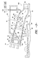
FIG. 2 is a side cutaway view of various components of a gas turbine system according to one embodiment of the present disclosure; -
FIG. 3 is a side cutaway view of various components of a gas turbine system according to another embodiment of the present disclosure; -
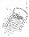
FIG. 4 is a perspective cutaway view of various components of a combustor assembly according to one embodiment of the present disclosure; and -
FIG. 5 is a front view image of a head end of a fuel nozzle assembly according to one embodiment of the present disclosure. - Reference now will be made in detail to embodiments of the invention, one or more examples of which are illustrated in the drawings. Each example is provided by way of explanation of the invention, not limitation of the invention. In fact, it will be apparent to those skilled in the art that various modifications and variations can be made in the present invention without departing from the scope or spirit of the invention. For instance, features illustrated or described as part of one embodiment can be used with another embodiment to yield a still further embodiment. Thus, it is intended that the present invention covers such modifications and variations as come within the scope of the appended claims and their equivalents.
-
FIG. 1 is a schematic diagram of aturbine system 10, which in exemplary embodiments is agas turbine system 10. Thesystem 10 may include acompressor assembly 12, acombustor assembly 14, and aturbine assembly 16. Thecombustor assembly 14 typically includes a plurality ofcombustors 15 disposed in a generally annular array. Thecompressor assembly 12 andturbine assembly 16 may be coupled by ashaft 18. Theshaft 18 may be a single shaft or a plurality of shaft segments coupled together to formshaft 18.Shaft 18 may be directly or indirectly connected to a load, such as a generator of electric power. - As illustrated in
FIGS. 2 and3 , thecombustor assembly 14 is generally fluidly coupled to thecompressor assembly 12 and theturbine assembly 16. Thecompressor assembly 12 may include adiffuser 20 and adischarge plenum 22 that are coupled to each other in fluid communication, so as to facilitate the channeling of a workingfluid 24 to thecombustor assembly 14. As shown, at least a portion of thedischarge plenum 22 is defined by anouter casing 25, such as a compressor discharge casing. After being compressed in thecompressor assembly 12, workingfluid 24 may flow through thediffuser 20 and be provided to thedischarge plenum 22. The workingfluid 24 may then flow from thedischarge plenum 22 to thecombustor assembly 14, such as to thecombustors 15 thereof, wherein the workingfluid 24 is combined with fuel fromfuel nozzle assemblies 26, one or more of which are included with eachcombustor 15 incombustor assembly 14. - Suitable fuels according to the present disclosure include any suitable gas or liquid fuels, such as natural gas or an oil. Further, suitable fuels include fuels and fuel compositions that may be utilized in flexible fuel gas turbine systems, such as fuel compositions including hydrogen, carbon monoxide, methane, other hydrocarbons, and/or inerts, such as nitrogen.
- After mixing with the fuel, the working
fluid 24 / fuel mixture may be ignited within acombustion chamber 28 in acombustor 15 to createhot gas flow 30 through thatcombustor 15. Thehot gas flow 30 may be channeled through thecombustion chamber 28 along ahot gas path 32 into atransition piece cavity 34 and through aturbine nozzle 36 to theturbine assembly 16. - A
combustor 15 may comprise a hollow annular wall configured to facilitate workingfluid 24. For example, thecombustor 15 may include acombustor liner 40 disposed within aflow sleeve 42. The arrangement of thecombustor liner 40 and theflow sleeve 42, as shown inFIG. 2 , is generally concentric and may define an annular passage or flowpath 44 therebetween. In certain embodiments, theflow sleeve 42 and thecombustor liner 40 may define a first or upstream hollow annular wall of thecombustor 15. Theflow sleeve 42 may include a plurality ofinlets 46, which provide a flow path for at least a portion of the workingfluid 24 from thecompressor 12 through thedischarge plenum 22 into theflow path 44. In other words, theflow sleeve 42 may be perforated with a pattern of openings to define a perforated annular wall. The interior of thecombustor liner 40 may define the substantially cylindrical orannular combustion chamber 28 and at least partially define thehot gas path 32 through whichhot gas flow 30 may be directed. - Downstream from the
combustor liner 40 and theflow sleeve 42, animpingement sleeve 50 may be coupled to theflow sleeve 42. Theflow sleeve 42 may include a mountingflange 52 configured to receive a mountingmember 54 of theimpingement sleeve 50. Atransition piece 56 may be disposed within theimpingement sleeve 50, such that theimpingement sleeve 50 surrounds at least a portion of thetransition piece 56. A concentric arrangement of theimpingement sleeve 50 and thetransition piece 56 may define an annular passage or flowpath 58 therebetween. Theimpingement sleeve 50 may include a plurality ofinlets 60, which may provide a flow path for at least a portion of the workingfluid 24 from thecompressor assembly 12 through thedischarge plenum 22 into theflow path 58. In other words, theimpingement sleeve 50 may be perforated with a pattern of openings to define a perforated annular wall.Interior cavity 34 of thetransition piece 56 may further definehot gas path 32 through whichhot gas flow 30 from thecombustion chamber 28 may be directed into theturbine 16. - As shown, the
flow path 58 is fluidly coupled to theflow path 44. Thus, together, theflow paths fluid 24 from thecompressor assembly 12 and thedischarge plenum 22 to thefuel nozzle assembly 26, while also cooling thecombustor 15. - As discussed above, the
turbine system 10, in operation, mayintake working fluid 24 and provide the workingfluid 24 to thecompressor assembly 12. Thecompressor assembly 12, which is driven by theshaft 18, may rotate and compress the workingfluid 24. The compressed workingfluid 24 may then be discharged into thediffuser 20. The majority of the compressed workingfluid 24 may then be discharged from thecompressor assembly 12, by way of thediffuser 20, through thedischarge plenum 22 and into thecombustor assembly 14 orcombustors 15 thereof. Additionally, a small portion (not shown) of the compressed workingfluid 24 may be channeled downstream for cooling of other components of theturbine engine 10. - As shown, the
outer casing 25 defining thedischarge plenum 22 may at least partially surround theimpingement sleeve 50 and theflow sleeve 42. A portion of the compressed workingfluid 24 within thedischarge plenum 22 may enter theflow path 58 by way of theinlets 60. The workingfluid 24 in theflow path 58 may then be channeled upstream throughflow path 44, such that the workingfluid 24 is directed over thecombustor liner 34. Thus, a flow path is defined in the upstream direction by flow path 58 (formed byimpingement sleeve 50 and transition piece 56) and flow path 44 (formed byflow sleeve 42 and combustor liner 40). Accordingly, flowpath 44 may receive workingfluid 24 from both flowpath 58 andinlets 46. The workingfluid 24 flowing through theflow path 44 may then be channeled upstream towards thefuel nozzle assemblies 26, as discussed above. - The present disclosure may further be directed to a
system 100 for controlling acombustor assembly 14.Such system 100 may be included in aturbine system 10, and may allow for control and elimination of combustion instabilities, such as flashback, flame holding, fuel or air path blockages, combustor blowout, or other suitable occurrences, during operation of thecombustor assembly 14 andsystem 10. - A
system 100 according to the present disclosure may include acombustor assembly 14, which may include one ormore combustors 15 and one or morefuel nozzle assemblies 26. As shown inFIG. 4 , acombustor 15 may include casing 102, which may be formed from, for example, acombustor liner 40 and a separate orintegrated transition piece 56. Thefuel nozzle assembly 26 may be positioned at least partially within thecasing 102, as shown. Afuel nozzle assembly 26 according to the present disclosure may include one ormore fuel nozzles 104. For example, in one embodiment, afuel nozzle assembly 26 may include sevenfuel nozzles 104. Alternatively, however, afuel nozzle assembly 26 according to the present disclosure may include one, two, three, four, five, six, eight, nine, ten, ormore fuel nozzles 104, as desired or required. In some embodiments, afuel nozzle assembly 26 may further include acap assembly 106. Thecap assembly 106 is provided for mounting thevarious fuel nozzles 104 thereto. Alternatively, thefuel nozzles 104 are mounted to each other, such that nocap assembly 106 is required. Afuel nozzle assembly 26 according to the present disclosure further defines ahead end 108. Thehead end 108 is the end surface of theassembly 26 within thecasing 102 that faces thecombustion chamber 28, and from which fuel and workingfluid 24 are exhausted for combustion. - A
fuel nozzle assembly 26 according to the present disclosure may, in exemplary embodiments, include micro-mixer fuel nozzles and/or other suitable micro-mixer technology as shown. Alternatively, however, thefuel nozzle assembly 26 may include any suitable fuel nozzles and/or other suitable components, such as swozzles, as desired or required. - It should be understood that a
fuel nozzle assembly 26 according to the present disclosure need not be a primary fuel nozzle assembly positioned upstream of the flow of fuel and workingfluid 24 as shown. Rather, afuel nozzle assembly 26 according to the present disclosure may be any suitable primary, secondary, or other fuel nozzle assembly that generally flows fuel and workingfluid 24 into thecasing 102. For example, in some embodiments, afuel nozzle assembly 26 may be a late lean injectionfuel nozzle assembly 26 positioned downstream of the location of a primary fuel nozzle relative to the flow of fuel and workingfluid 24. - A
system 100 according to the present disclosure further includes aviewing device 110. Theviewing device 110 may be configured for capturing an image of at least a portion of thehead end 108. For example, thehead end 108 may be a camera, a camcorder, or any other suitable device for recording and/or storing images. Theviewing device 110 may capture images in the visible spectrum, infrared spectrum, or ultraviolet spectrum, or any other images at any suitable wavelengths or ranges of wavelengths. In some embodiments, as shown inFIG. 2 , theviewing device 110 may be mounted at least partially within thecasing 102, such that a viewfinder or other viewing apparatus of theviewing device 110 has a direct view of at least a portion of thehead end 108. Acooling device 112 may be connected to theviewing device 110 for cooling theviewing device 110 during operation of thecombustion assembly 14. Thecooling device 112 may utilize, for example, a closed loop air system, a closed loop water system, an open loop air system, or any other suitable cooling system using any suitable fluids. In alternative embodiments, as shown inFIG. 3 , theviewing device 110 may be mounted outside of thecasing 102. Asuitable optics train 114 may be connected to theviewing device 110 and be mounted at least partially within thecasing 102 such that a viewfinder or other viewing apparatus of theviewing device 110 has an indirect view through the optics train 114 of at least a portion of thehead end 108. Acooling device 112 may be connected to the optics train 114 and/orviewing device 110. - A
system 100 according to the present disclosure may further include aprocessor 120. Theprocessor 120 may be communicatively coupled to theviewing device 110. For example, adata cable 122 or other suitable cable or physical coupling device may manually couple theviewing device 110 to theprocessor 120, or theprocessor 120 may be wirelessly coupled to theviewing device 110, such as through an infra-red, cellular, sonic, optical, or radio frequency based coupling. - Further, the
processor 120 may be configured to compare an image captured by theviewing device 110 to a standard image for thehead end 108. For example, a standard image of at least a portion of thehead end 108 may be taken when, for example, no combustion instabilities are occurring, and may thus establish a baseline view of thehead end 108. This standard image may be stored in theprocessor 120. Images taken during operation of thecombustor assembly 14 may then be compared to this standard image. The detection of differences between an image and the standard image by theprocessor 120 may allow theprocessor 120 to indicate the existence of, for example, a combustion instability. For example, a flashback may be indicated by a small region of high luminosity and white light in the visible spectrum. A blockage may be indicated by a local region of moderate luminosity and a red or orange color, or could result in a local area of reduced temperature on thehead end 108 that would be detectable on an infrared image. - In some embodiments, the
processor 120 may further be configured to convert the image, as well as the standard image, into a temperature map, a color spectrum map, or a brightness map. For example, theviewing device 110 may include various devices and apparatus for detecting temperature on the surface of thehead end 108, the coloring of the surface of thehead end 108, or the brightness of the surface of thehead end 108. An image may then be converted, using differences in temperature, color, or brightness at various locations on the surface of thehead end 108, to a temperature map, a color spectrum map, or a brightness map. The standard image may similarly be converted, and these converted images thus compared. -
FIG. 5 illustrates an image of one embodiment of ahead end 108. An image, including a standard image, according to the present disclosure, may include a plurality ofpixels 124, as shown inFIG. 5 . The image may be subdivided intosuch pixels 124 by theviewing device 110. The number ofpixels 124 into which an image is divided may be based on the resolution of the viewing device 110 - a higher resolution may result in more,smaller pixels 124, for example. Eachpixel 124, or azone 126 ofpixels 124, of an image may be compared to therespective pixel 124 orzone 126 ofpixels 124 of the standard image. For example, the pixels of zone 1 in an image may be compared to the respective pixels of zone 1 of the standard image. - After comparison of an image to a standard image, the
processor 120 may determine whether the image and standard image, such as various portions thereof, are similar, such as based on color, brightness, temperature, or any other suitable characteristic, or whether the image and standard image, such as any various portions thereof, are different. If there are any differences for any portions of the image, such as anypixels 124, pluralities ofpixels 124,zones 126, or pluralities ofzones 126, that are outside of a pre-defmed range relative to the standard image, these differences may indicate the existence of a combustion instability. For example,reference numeral 128 indicates one example of an indicator of a difference for a plurality ofpixels 124 within azone 126 that would indicate the existence of a combustion instability. - Any suitable imaging software, such as any software that can manipulate and compare images, may be utilized in the
processor 120 to provide the above-described imaging capabilities. Further, theprocessor 120 may be incorporated into a suitable controller, such as a handheld remote, a personal digital assistant, cellular telephone, a separate pendant controller, or a computer. Theprocessor 120 may be operated by a human operator, or may be partially or fully automated through the use of suitable programming logic incorporated into theprocessor 120. - A
system 100 may further include acombustor control system 130. Thecombustor control system 130 may control various variables for thecombustor assembly 14, such as fuel flow rate into afuel nozzle assembly 26, workingfluid 24 flow rate into acombustor 15, fuel split (percentage of total fuel) betweenvarious fuel nozzles 104 orfuel nozzle assemblies 26 in acombustor 15, fuel split betweenvarious combustors 15 of acombustor assembly 14, workingfluid 24 split betweenvarious combustors 15 of acombustor assembly 14, flow direction, and/or inlet guide vane angle. In one embodiment, for example, thecombustor control system 130 may control the amounts of various gases, such as, for example, methane, hydrogen, carbon monoxide, carbon dioxide, and/or nitrogen, in the fuel supplied to thefuel nozzles 104 andfuel nozzle assemblies 26. Thus, thecontrol system 130 may include a suitable processor, hardware, and/or software for controlling such variables, and may be communicatively coupled with the various components of thecombustor assembly 14, such as thecombustors 15 andfuel nozzle assemblies 26, for controlling such variables. - The
combustor control system 130 may further be communicatively coupled to theprocessor 120. For example, theprocessor 120 may be a component of thesystem 130, or theprocessor 120 may be coupled to thesystem 130 through a wired or wireless connection. Thesystem 130 may be further configured to perform a responsive action if at least a portion of an image, such as apixel 124, a plurality ofpixels 124, azone 126, or a plurality ofzones 126, is outside of a pre-defined range relative to the standard image. The responsive action may a change in fuel flow rate into afuel nozzle assembly 26, workingfluid 24 flow rate into acombustor 15, fuel split betweenvarious combustors 15 of acombustor assembly 14, workingfluid 24 split betweenvarious combustors 15 of acombustor assembly 14, flow direction, and/or inlet guide vane angle. - For example, in some embodiments, methane may be added to the fuel being provided to a
fuel nozzle assembly 26. For example, a relatively small amount of methane, such less than or equal to approximately 2%, less than or equal to approximately 5%, or less than or equal to approximately 10% methane by volume may be added. The inventors of the present disclosure have discovered that the addition of methane is particularly effective at eliminating combustion instabilities. Additionally or alternatively, nitrogen or another inert gas may be added. It should be understood, however, that the present disclosure is not limited to the addition of any specific amounts of methane or nitrogen, and rather that the addition or subtraction of any suitable fluid is within the scope and spirit of the present disclosure. - Thus, a
system 100 according to the present disclosure may advantageously detect and eliminate combustion instabilities in acombustor assembly 14. Operation of thesystem 100 may be in real-time, such that combustion instabilities are eliminated in real-time and thesystem 100 may continue with normal operation after such elimination. For example, in exemplary embodiments, images may be repeatedly captured at a specified time interval and then compared in real time after capturing to the standard image. - The present disclosure may further be directed to a method for controlling a
combustor assembly 14. The method may include, for example, capturing an image of at least a portion of ahead end 108 of afuel nozzle assembly 26 for acombustor 15, as discussed above. The method may further include, for example, comparing the image to a standard image for thehead end 108, as discussed above. - In some embodiments, the method may further include, for example, converting the image into a temperature map, a color spectrum map, or a brightness map, as discussed above.
- In some embodiments, the method may further include performing a responsive action, as discussed above. The responsive action may be performed if at least a portion of the image is outside of a pre-defined range relative to the standard image.
- This written description uses examples to disclose the invention, including the best mode, and also to enable any person skilled in the art to practice the invention, including making and using any devices or systems and performing any incorporated methods. The patentable scope of the invention is defined by the claims, and may include other examples that occur to those skilled in the art. Such other examples are intended to be within the scope of the claims if they include structural elements that do not differ from the literal language of the claims, or if they include equivalent structural elements with insubstantial differences from the literal languages of the claims.
Claims (15)
- A system (100) for controlling a combustor assembly (14), the system (100) comprising:a combustor assembly (14) comprising a combustor (15) and a fuel nozzle assembly (26), the combustor (15) comprising a casing (102), the fuel nozzle assembly (26) positioned at least partially within the casing (102) and comprising a fuel nozzle (104), the fuel nozzle assembly (26) further defining a head end (108);a viewing device (110) configured for capturing an image of at least a portion of the head end (108); anda processor (120) communicatively coupled to the viewing device (110), the processor (120) configured to compare the image to a standard image for the head end (108).
- The system (100) of claim 1, wherein the viewing device (110) is a camera.
- The system (100) of claim 1 or 2, wherein the viewing device (110) captures visual images.
- The system (100) of any of claims 1 to 3, wherein the viewing device (110) captures infrared images.
- The system (100) of any of claims 1 to 4, wherein the viewing device (110) is mounted at least partially within the casing (102).
- The system (100) of any of claims 1 to 5, wherein the processor (120) is further configured to convert the image into one of a temperature map, a color spectrum map, or a brightness map.
- The system (100) of any of claims 1 to 6, wherein the processor (120) is further communicatively coupled to a combustor control system (130), and wherein the combustor control system (130) performs a responsive action if at least a portion of the image is outside of a pre-defined range relative to the standard image.
- The system (100) of any of claims 1 to 7, wherein the image comprises a plurality of pixels (124), and wherein each of the plurality of pixels (124) is compared to a respective pixel (124) of the standard image.
- The system (100) of any of claims 1 to 8, wherein the fuel nozzle assembly (26) further comprises a cap assembly (106).
- The system (100) of any of claims 1 to 9, wherein the fuel nozzle assembly (26) comprises a plurality of fuel nozzles (104).
- A gas turbine, comprising the system (100) of any of claims 1 to 10.
- A method for controlling a combustor assembly (14), the method comprising:capturing an image of at least a portion of a head end (108) of a fuel nozzle assembly (26) for a combustor (15), the combustor (15) comprising a casing (102), the fuel nozzle assembly (26) positioned at least partially within the casing (102) and comprising a fuel nozzle (104), the fuel nozzle assembly (26) further defining the head end (108); andcomparing the image to a standard image for the head end (108).
- The method of claim 12, further comprising converting the image into one of a temperature map, a color spectrum map, or a brightness map.
- The method of claim 12 or 13, further comprising performing a responsive action if at least a portion of the image is outside of a pre-defined range relative to the standard image.
- The method of any of claims 12 to 14, wherein the image comprises a plurality of pixels (124), and wherein the comparing step comprises comparing each of the plurality of pixels (124) to a respective pixel (124) of the standard image.
Applications Claiming Priority (1)
| Application Number | Priority Date | Filing Date | Title |
|---|---|---|---|
| US13/229,950 US8387399B1 (en) | 2011-09-12 | 2011-09-12 | System and method for controlling a combustor assembly |
Publications (2)
| Publication Number | Publication Date |
|---|---|
| EP2568219A1 true EP2568219A1 (en) | 2013-03-13 |
| EP2568219B1 EP2568219B1 (en) | 2016-06-29 |
Family
ID=46508249
Family Applications (1)
| Application Number | Title | Priority Date | Filing Date |
|---|---|---|---|
| EP12175098.8A Active EP2568219B1 (en) | 2011-09-12 | 2012-07-05 | Arrangement comprising a combustor assembly and a system for controlling the combustor assembly and method for controlling a combustor assembly |
Country Status (3)
| Country | Link |
|---|---|
| US (1) | US8387399B1 (en) |
| EP (1) | EP2568219B1 (en) |
| CN (1) | CN102997277B (en) |
Cited By (1)
| Publication number | Priority date | Publication date | Assignee | Title |
|---|---|---|---|---|
| WO2019035807A1 (en) * | 2017-08-15 | 2019-02-21 | Siemens Energy, Inc. | Embedded imaging unit for high temperature and pressure applications |
Families Citing this family (6)
| Publication number | Priority date | Publication date | Assignee | Title |
|---|---|---|---|---|
| US20150104748A1 (en) * | 2013-10-14 | 2015-04-16 | Clearsign Combustion Corporation | Electrodynamic combustion control (ecc) technology for biomass and coal systems |
| KR101838822B1 (en) * | 2013-10-18 | 2018-03-14 | 미츠비시 쥬고교 가부시키가이샤 | Fuel injector |
| US11300290B2 (en) * | 2018-04-03 | 2022-04-12 | Mestek, Inc. | High turndown boiler and system and method for controlling a boiler |
| US10935431B2 (en) * | 2018-09-21 | 2021-03-02 | Raytheon Technologies Corporation | Sensor arrangement for measuring gas turbine combustor temperatures |
| DE102020104195A1 (en) * | 2020-02-18 | 2021-08-19 | Vaillant Gmbh | Heat cell with optical sensor unit |
| CN119554662B (en) * | 2025-01-03 | 2026-04-07 | 中国航发湖南动力机械研究所 | Hydrogen fuel staged combustion unit, full-ring combustion chamber and aeroengine |
Citations (3)
| Publication number | Priority date | Publication date | Assignee | Title |
|---|---|---|---|---|
| US4520390A (en) * | 1982-08-25 | 1985-05-28 | Forney Engineering Company | Burner monitoring system |
| US20100180564A1 (en) * | 2009-01-21 | 2010-07-22 | General Electric Company | Systems and Methods for Mitigating a Flashback Condition in a Premixed Combustor |
| CH702607A2 (en) * | 2010-01-25 | 2011-07-29 | Gen Electric | System for detecting and controlling flashback and flame holding in combustion chamber of gas turbine, has flame indicator which is arranged in combustion chamber of gas turbine, and flame indicator is configured to generate light |
Family Cites Families (14)
| Publication number | Priority date | Publication date | Assignee | Title |
|---|---|---|---|---|
| JPS59195012A (en) | 1983-04-20 | 1984-11-06 | Hitachi Ltd | Combustion control method |
| US5148667A (en) * | 1990-02-01 | 1992-09-22 | Electric Power Research Institute | Gas turbine flame diagnostic monitor |
| US5249954A (en) | 1992-07-07 | 1993-10-05 | Electric Power Research Institute, Inc. | Integrated imaging sensor/neural network controller for combustion systems |
| JPH06273322A (en) | 1993-03-17 | 1994-09-30 | Hitachi Ltd | Camera, spectroscopic system, and combustion evaluation device using these |
| JPH07332609A (en) * | 1994-06-06 | 1995-12-22 | Hitachi Ltd | Fuel-air ratio control system for gas turbine combustor |
| US5544478A (en) * | 1994-11-15 | 1996-08-13 | General Electric Company | Optical sensing of combustion dynamics |
| US5978525A (en) * | 1996-06-24 | 1999-11-02 | General Electric Company | Fiber optic sensors for gas turbine control |
| US6599028B1 (en) * | 1997-06-17 | 2003-07-29 | General Electric Company | Fiber optic sensors for gas turbine control |
| US7334413B2 (en) * | 2004-05-07 | 2008-02-26 | Rosemount Aerospace Inc. | Apparatus, system and method for observing combustion conditions in a gas turbine engine |
| US7462220B2 (en) * | 2005-08-31 | 2008-12-09 | General Electric Company | Methods and systems for detecting filter rupture |
| US7336897B2 (en) | 2005-09-20 | 2008-02-26 | General Electric Company | Liquid-cooled combustion camera |
| JP5229767B2 (en) * | 2006-07-31 | 2013-07-03 | 独立行政法人 宇宙航空研究開発機構 | Analysis method and apparatus in laser-induced plasma spectroscopy |
| US7486864B2 (en) | 2007-04-05 | 2009-02-03 | Siemens Energy, Inc. | Monitoring system for turbine engine |
| US8752362B2 (en) | 2009-01-15 | 2014-06-17 | General Electric Company | Optical flame holding and flashback detection |
-
2011
- 2011-09-12 US US13/229,950 patent/US8387399B1/en active Active
-
2012
- 2012-07-05 EP EP12175098.8A patent/EP2568219B1/en active Active
- 2012-07-12 CN CN201210240580.2A patent/CN102997277B/en not_active Expired - Fee Related
Patent Citations (3)
| Publication number | Priority date | Publication date | Assignee | Title |
|---|---|---|---|---|
| US4520390A (en) * | 1982-08-25 | 1985-05-28 | Forney Engineering Company | Burner monitoring system |
| US20100180564A1 (en) * | 2009-01-21 | 2010-07-22 | General Electric Company | Systems and Methods for Mitigating a Flashback Condition in a Premixed Combustor |
| CH702607A2 (en) * | 2010-01-25 | 2011-07-29 | Gen Electric | System for detecting and controlling flashback and flame holding in combustion chamber of gas turbine, has flame indicator which is arranged in combustion chamber of gas turbine, and flame indicator is configured to generate light |
Cited By (1)
| Publication number | Priority date | Publication date | Assignee | Title |
|---|---|---|---|---|
| WO2019035807A1 (en) * | 2017-08-15 | 2019-02-21 | Siemens Energy, Inc. | Embedded imaging unit for high temperature and pressure applications |
Also Published As
| Publication number | Publication date |
|---|---|
| CN102997277B (en) | 2016-08-03 |
| US8387399B1 (en) | 2013-03-05 |
| US20130061593A1 (en) | 2013-03-14 |
| CN102997277A (en) | 2013-03-27 |
| EP2568219B1 (en) | 2016-06-29 |
Similar Documents
| Publication | Publication Date | Title |
|---|---|---|
| EP2568219B1 (en) | Arrangement comprising a combustor assembly and a system for controlling the combustor assembly and method for controlling a combustor assembly | |
| US8432440B2 (en) | System and method for adjusting engine parameters based on flame visualization | |
| US8899049B2 (en) | System and method for controlling combustor operating conditions based on flame detection | |
| Esclapez et al. | Fuel effects on lean blow-out in a realistic gas turbine combustor | |
| US9017435B2 (en) | Gasifier monitor and control system | |
| US8122725B2 (en) | Methods and systems for operating gas turbine engines | |
| US7921653B2 (en) | Internal manifold air extraction system for IGCC combustor and method | |
| CN104541104A (en) | Sequential combustion with dilution gas mixer | |
| US5794549A (en) | Combustion optimization system | |
| EP2669577A1 (en) | Flame detection in no-flame region of gas turbine | |
| CA2843425C (en) | Laser-ignition combustor for gas turbine engine | |
| US7827777B2 (en) | Combustor with reduced carbon monoxide emissions | |
| CN116828150A (en) | A device and method for online monitoring of burner flame stability | |
| EP2557361A2 (en) | System and method for monitoring a combustor | |
| Andracher et al. | Progress on combined optic-acoustic monitoring of combustion in a gas turbine | |
| CN107228017A (en) | It is provided with the method for the gas-turbine plant and control gas-turbine plant of the unstable detection of thermoacoustic | |
| CN107228382A (en) | Gas turbine burner component with optic probe | |
| JPH07332609A (en) | Fuel-air ratio control system for gas turbine combustor | |
| JPS62105016A (en) | Combustor flame monitoring device | |
| EP2629015A2 (en) | Outer fuel nozzle inlet flow conditioner interface to end cap | |
| JPH0678937B2 (en) | Gas turbine combustor flame monitoring device | |
| HK1159904A (en) | Image sensing system, software, apparatus and method for controlling combustion equipment |
Legal Events
| Date | Code | Title | Description |
|---|---|---|---|
| PUAI | Public reference made under article 153(3) epc to a published international application that has entered the european phase |
Free format text: ORIGINAL CODE: 0009012 |
|
| AK | Designated contracting states |
Kind code of ref document: A1 Designated state(s): AL AT BE BG CH CY CZ DE DK EE ES FI FR GB GR HR HU IE IS IT LI LT LU LV MC MK MT NL NO PL PT RO RS SE SI SK SM TR |
|
| AX | Request for extension of the european patent |
Extension state: BA ME |
|
| 17P | Request for examination filed |
Effective date: 20130913 |
|
| RBV | Designated contracting states (corrected) |
Designated state(s): AL AT BE BG CH CY CZ DE DK EE ES FI FR GB GR HR HU IE IS IT LI LT LU LV MC MK MT NL NO PL PT RO RS SE SI SK SM TR |
|
| GRAP | Despatch of communication of intention to grant a patent |
Free format text: ORIGINAL CODE: EPIDOSNIGR1 |
|
| RIC1 | Information provided on ipc code assigned before grant |
Ipc: F23R 3/28 20060101ALI20160304BHEP Ipc: F23N 5/08 20060101AFI20160304BHEP |
|
| INTG | Intention to grant announced |
Effective date: 20160329 |
|
| GRAS | Grant fee paid |
Free format text: ORIGINAL CODE: EPIDOSNIGR3 |
|
| GRAA | (expected) grant |
Free format text: ORIGINAL CODE: 0009210 |
|
| AK | Designated contracting states |
Kind code of ref document: B1 Designated state(s): AL AT BE BG CH CY CZ DE DK EE ES FI FR GB GR HR HU IE IS IT LI LT LU LV MC MK MT NL NO PL PT RO RS SE SI SK SM TR |
|
| REG | Reference to a national code |
Ref country code: GB Ref legal event code: FG4D |
|
| REG | Reference to a national code |
Ref country code: CH Ref legal event code: EP |
|
| REG | Reference to a national code |
Ref country code: AT Ref legal event code: REF Ref document number: 809417 Country of ref document: AT Kind code of ref document: T Effective date: 20160715 |
|
| REG | Reference to a national code |
Ref country code: FR Ref legal event code: PLFP Year of fee payment: 5 |
|
| REG | Reference to a national code |
Ref country code: IE Ref legal event code: FG4D |
|
| REG | Reference to a national code |
Ref country code: DE Ref legal event code: R096 Ref document number: 602012019900 Country of ref document: DE |
|
| REG | Reference to a national code |
Ref country code: LT Ref legal event code: MG4D |
|
| PG25 | Lapsed in a contracting state [announced via postgrant information from national office to epo] |
Ref country code: NO Free format text: LAPSE BECAUSE OF FAILURE TO SUBMIT A TRANSLATION OF THE DESCRIPTION OR TO PAY THE FEE WITHIN THE PRESCRIBED TIME-LIMIT Effective date: 20160929 Ref country code: LT Free format text: LAPSE BECAUSE OF FAILURE TO SUBMIT A TRANSLATION OF THE DESCRIPTION OR TO PAY THE FEE WITHIN THE PRESCRIBED TIME-LIMIT Effective date: 20160629 Ref country code: FI Free format text: LAPSE BECAUSE OF FAILURE TO SUBMIT A TRANSLATION OF THE DESCRIPTION OR TO PAY THE FEE WITHIN THE PRESCRIBED TIME-LIMIT Effective date: 20160629 |
|
| REG | Reference to a national code |
Ref country code: NL Ref legal event code: MP Effective date: 20160629 |
|
| PG25 | Lapsed in a contracting state [announced via postgrant information from national office to epo] |
Ref country code: NL Free format text: LAPSE BECAUSE OF FAILURE TO SUBMIT A TRANSLATION OF THE DESCRIPTION OR TO PAY THE FEE WITHIN THE PRESCRIBED TIME-LIMIT Effective date: 20160629 Ref country code: LV Free format text: LAPSE BECAUSE OF FAILURE TO SUBMIT A TRANSLATION OF THE DESCRIPTION OR TO PAY THE FEE WITHIN THE PRESCRIBED TIME-LIMIT Effective date: 20160629 Ref country code: SE Free format text: LAPSE BECAUSE OF FAILURE TO SUBMIT A TRANSLATION OF THE DESCRIPTION OR TO PAY THE FEE WITHIN THE PRESCRIBED TIME-LIMIT Effective date: 20160629 Ref country code: HR Free format text: LAPSE BECAUSE OF FAILURE TO SUBMIT A TRANSLATION OF THE DESCRIPTION OR TO PAY THE FEE WITHIN THE PRESCRIBED TIME-LIMIT Effective date: 20160629 Ref country code: RS Free format text: LAPSE BECAUSE OF FAILURE TO SUBMIT A TRANSLATION OF THE DESCRIPTION OR TO PAY THE FEE WITHIN THE PRESCRIBED TIME-LIMIT Effective date: 20160629 Ref country code: GR Free format text: LAPSE BECAUSE OF FAILURE TO SUBMIT A TRANSLATION OF THE DESCRIPTION OR TO PAY THE FEE WITHIN THE PRESCRIBED TIME-LIMIT Effective date: 20160930 |
|
| REG | Reference to a national code |
Ref country code: AT Ref legal event code: MK05 Ref document number: 809417 Country of ref document: AT Kind code of ref document: T Effective date: 20160629 |
|
| PG25 | Lapsed in a contracting state [announced via postgrant information from national office to epo] |
Ref country code: BE Free format text: LAPSE BECAUSE OF NON-PAYMENT OF DUE FEES Effective date: 20160731 |
|
| PG25 | Lapsed in a contracting state [announced via postgrant information from national office to epo] |
Ref country code: IS Free format text: LAPSE BECAUSE OF FAILURE TO SUBMIT A TRANSLATION OF THE DESCRIPTION OR TO PAY THE FEE WITHIN THE PRESCRIBED TIME-LIMIT Effective date: 20161029 Ref country code: SK Free format text: LAPSE BECAUSE OF FAILURE TO SUBMIT A TRANSLATION OF THE DESCRIPTION OR TO PAY THE FEE WITHIN THE PRESCRIBED TIME-LIMIT Effective date: 20160629 Ref country code: RO Free format text: LAPSE BECAUSE OF FAILURE TO SUBMIT A TRANSLATION OF THE DESCRIPTION OR TO PAY THE FEE WITHIN THE PRESCRIBED TIME-LIMIT Effective date: 20160629 Ref country code: CZ Free format text: LAPSE BECAUSE OF FAILURE TO SUBMIT A TRANSLATION OF THE DESCRIPTION OR TO PAY THE FEE WITHIN THE PRESCRIBED TIME-LIMIT Effective date: 20160629 Ref country code: EE Free format text: LAPSE BECAUSE OF FAILURE TO SUBMIT A TRANSLATION OF THE DESCRIPTION OR TO PAY THE FEE WITHIN THE PRESCRIBED TIME-LIMIT Effective date: 20160629 |
|
| PG25 | Lapsed in a contracting state [announced via postgrant information from national office to epo] |
Ref country code: PL Free format text: LAPSE BECAUSE OF FAILURE TO SUBMIT A TRANSLATION OF THE DESCRIPTION OR TO PAY THE FEE WITHIN THE PRESCRIBED TIME-LIMIT Effective date: 20160629 Ref country code: SM Free format text: LAPSE BECAUSE OF FAILURE TO SUBMIT A TRANSLATION OF THE DESCRIPTION OR TO PAY THE FEE WITHIN THE PRESCRIBED TIME-LIMIT Effective date: 20160629 Ref country code: BE Free format text: LAPSE BECAUSE OF FAILURE TO SUBMIT A TRANSLATION OF THE DESCRIPTION OR TO PAY THE FEE WITHIN THE PRESCRIBED TIME-LIMIT Effective date: 20160629 Ref country code: AT Free format text: LAPSE BECAUSE OF FAILURE TO SUBMIT A TRANSLATION OF THE DESCRIPTION OR TO PAY THE FEE WITHIN THE PRESCRIBED TIME-LIMIT Effective date: 20160629 Ref country code: ES Free format text: LAPSE BECAUSE OF FAILURE TO SUBMIT A TRANSLATION OF THE DESCRIPTION OR TO PAY THE FEE WITHIN THE PRESCRIBED TIME-LIMIT Effective date: 20160629 Ref country code: PT Free format text: LAPSE BECAUSE OF FAILURE TO SUBMIT A TRANSLATION OF THE DESCRIPTION OR TO PAY THE FEE WITHIN THE PRESCRIBED TIME-LIMIT Effective date: 20161031 |
|
| REG | Reference to a national code |
Ref country code: DE Ref legal event code: R097 Ref document number: 602012019900 Country of ref document: DE |
|
| REG | Reference to a national code |
Ref country code: IE Ref legal event code: MM4A |
|
| PLBE | No opposition filed within time limit |
Free format text: ORIGINAL CODE: 0009261 |
|
| STAA | Information on the status of an ep patent application or granted ep patent |
Free format text: STATUS: NO OPPOSITION FILED WITHIN TIME LIMIT |
|
| PG25 | Lapsed in a contracting state [announced via postgrant information from national office to epo] |
Ref country code: DK Free format text: LAPSE BECAUSE OF FAILURE TO SUBMIT A TRANSLATION OF THE DESCRIPTION OR TO PAY THE FEE WITHIN THE PRESCRIBED TIME-LIMIT Effective date: 20160629 |
|
| 26N | No opposition filed |
Effective date: 20170330 |
|
| REG | Reference to a national code |
Ref country code: FR Ref legal event code: PLFP Year of fee payment: 6 |
|
| PG25 | Lapsed in a contracting state [announced via postgrant information from national office to epo] |
Ref country code: IE Free format text: LAPSE BECAUSE OF NON-PAYMENT OF DUE FEES Effective date: 20160705 |
|
| PG25 | Lapsed in a contracting state [announced via postgrant information from national office to epo] |
Ref country code: BG Free format text: LAPSE BECAUSE OF FAILURE TO SUBMIT A TRANSLATION OF THE DESCRIPTION OR TO PAY THE FEE WITHIN THE PRESCRIBED TIME-LIMIT Effective date: 20160929 Ref country code: SI Free format text: LAPSE BECAUSE OF FAILURE TO SUBMIT A TRANSLATION OF THE DESCRIPTION OR TO PAY THE FEE WITHIN THE PRESCRIBED TIME-LIMIT Effective date: 20160629 Ref country code: LU Free format text: LAPSE BECAUSE OF NON-PAYMENT OF DUE FEES Effective date: 20160705 |
|
| PGFP | Annual fee paid to national office [announced via postgrant information from national office to epo] |
Ref country code: CH Payment date: 20170727 Year of fee payment: 6 Ref country code: FR Payment date: 20170726 Year of fee payment: 6 |
|
| PG25 | Lapsed in a contracting state [announced via postgrant information from national office to epo] |
Ref country code: CY Free format text: LAPSE BECAUSE OF FAILURE TO SUBMIT A TRANSLATION OF THE DESCRIPTION OR TO PAY THE FEE WITHIN THE PRESCRIBED TIME-LIMIT Effective date: 20160629 Ref country code: HU Free format text: LAPSE BECAUSE OF FAILURE TO SUBMIT A TRANSLATION OF THE DESCRIPTION OR TO PAY THE FEE WITHIN THE PRESCRIBED TIME-LIMIT; INVALID AB INITIO Effective date: 20120705 |
|
| PG25 | Lapsed in a contracting state [announced via postgrant information from national office to epo] |
Ref country code: MC Free format text: LAPSE BECAUSE OF FAILURE TO SUBMIT A TRANSLATION OF THE DESCRIPTION OR TO PAY THE FEE WITHIN THE PRESCRIBED TIME-LIMIT Effective date: 20160629 Ref country code: MK Free format text: LAPSE BECAUSE OF FAILURE TO SUBMIT A TRANSLATION OF THE DESCRIPTION OR TO PAY THE FEE WITHIN THE PRESCRIBED TIME-LIMIT Effective date: 20160629 Ref country code: TR Free format text: LAPSE BECAUSE OF FAILURE TO SUBMIT A TRANSLATION OF THE DESCRIPTION OR TO PAY THE FEE WITHIN THE PRESCRIBED TIME-LIMIT Effective date: 20160629 Ref country code: MT Free format text: LAPSE BECAUSE OF NON-PAYMENT OF DUE FEES Effective date: 20160731 |
|
| PG25 | Lapsed in a contracting state [announced via postgrant information from national office to epo] |
Ref country code: AL Free format text: LAPSE BECAUSE OF FAILURE TO SUBMIT A TRANSLATION OF THE DESCRIPTION OR TO PAY THE FEE WITHIN THE PRESCRIBED TIME-LIMIT Effective date: 20160629 |
|
| REG | Reference to a national code |
Ref country code: CH Ref legal event code: PL |
|
| PG25 | Lapsed in a contracting state [announced via postgrant information from national office to epo] |
Ref country code: LI Free format text: LAPSE BECAUSE OF NON-PAYMENT OF DUE FEES Effective date: 20180731 Ref country code: CH Free format text: LAPSE BECAUSE OF NON-PAYMENT OF DUE FEES Effective date: 20180731 Ref country code: FR Free format text: LAPSE BECAUSE OF NON-PAYMENT OF DUE FEES Effective date: 20180731 |
|
| PGFP | Annual fee paid to national office [announced via postgrant information from national office to epo] |
Ref country code: GB Payment date: 20200624 Year of fee payment: 9 |
|
| GBPC | Gb: european patent ceased through non-payment of renewal fee |
Effective date: 20210705 |
|
| PG25 | Lapsed in a contracting state [announced via postgrant information from national office to epo] |
Ref country code: GB Free format text: LAPSE BECAUSE OF NON-PAYMENT OF DUE FEES Effective date: 20210705 |
|
| REG | Reference to a national code |
Ref country code: DE Ref legal event code: R081 Ref document number: 602012019900 Country of ref document: DE Owner name: GENERAL ELECTRIC TECHNOLOGY GMBH, CH Free format text: FORMER OWNER: GENERAL ELECTRIC COMPANY, SCHENECTADY, NY, US |
|
| PGFP | Annual fee paid to national office [announced via postgrant information from national office to epo] |
Ref country code: DE Payment date: 20250620 Year of fee payment: 14 |
|
| PGFP | Annual fee paid to national office [announced via postgrant information from national office to epo] |
Ref country code: IT Payment date: 20250619 Year of fee payment: 14 |