EP2568213A2 - Vehicular Headlamp - Google Patents
Vehicular Headlamp Download PDFInfo
- Publication number
- EP2568213A2 EP2568213A2 EP20120183155 EP12183155A EP2568213A2 EP 2568213 A2 EP2568213 A2 EP 2568213A2 EP 20120183155 EP20120183155 EP 20120183155 EP 12183155 A EP12183155 A EP 12183155A EP 2568213 A2 EP2568213 A2 EP 2568213A2
- Authority
- EP
- European Patent Office
- Prior art keywords
- shade
- movable shade
- drive motor
- section
- movable
- Prior art date
- Legal status (The legal status is an assumption and is not a legal conclusion. Google has not performed a legal analysis and makes no representation as to the accuracy of the status listed.)
- Withdrawn
Links
- 230000000903 blocking effect Effects 0.000 claims description 54
- 230000005540 biological transmission Effects 0.000 claims description 32
- 230000008859 change Effects 0.000 claims description 22
- 230000002093 peripheral effect Effects 0.000 claims description 4
- 230000007246 mechanism Effects 0.000 description 35
- 230000004048 modification Effects 0.000 description 13
- 238000012986 modification Methods 0.000 description 13
- 230000009467 reduction Effects 0.000 description 13
- 230000003247 decreasing effect Effects 0.000 description 10
- 230000002349 favourable effect Effects 0.000 description 9
- 230000005855 radiation Effects 0.000 description 8
- 230000007547 defect Effects 0.000 description 4
- 230000006866 deterioration Effects 0.000 description 3
- 238000004804 winding Methods 0.000 description 3
- 238000010276 construction Methods 0.000 description 2
- 230000007423 decrease Effects 0.000 description 2
- 238000003780 insertion Methods 0.000 description 2
- 230000037431 insertion Effects 0.000 description 2
- 238000005452 bending Methods 0.000 description 1
- 230000000149 penetrating effect Effects 0.000 description 1
Images



Classifications
-
- B—PERFORMING OPERATIONS; TRANSPORTING
- B60—VEHICLES IN GENERAL
- B60Q—ARRANGEMENT OF SIGNALLING OR LIGHTING DEVICES, THE MOUNTING OR SUPPORTING THEREOF OR CIRCUITS THEREFOR, FOR VEHICLES IN GENERAL
- B60Q1/00—Arrangement of optical signalling or lighting devices, the mounting or supporting thereof or circuits therefor
- B60Q1/02—Arrangement of optical signalling or lighting devices, the mounting or supporting thereof or circuits therefor the devices being primarily intended to illuminate the way ahead or to illuminate other areas of way or environments
- B60Q1/04—Arrangement of optical signalling or lighting devices, the mounting or supporting thereof or circuits therefor the devices being primarily intended to illuminate the way ahead or to illuminate other areas of way or environments the devices being headlights
- B60Q1/06—Arrangement of optical signalling or lighting devices, the mounting or supporting thereof or circuits therefor the devices being primarily intended to illuminate the way ahead or to illuminate other areas of way or environments the devices being headlights adjustable, e.g. remotely-controlled from inside vehicle
- B60Q1/076—Arrangement of optical signalling or lighting devices, the mounting or supporting thereof or circuits therefor the devices being primarily intended to illuminate the way ahead or to illuminate other areas of way or environments the devices being headlights adjustable, e.g. remotely-controlled from inside vehicle by electrical means including means to transmit the movements, e.g. shafts or joints
-
- F—MECHANICAL ENGINEERING; LIGHTING; HEATING; WEAPONS; BLASTING
- F21—LIGHTING
- F21S—NON-PORTABLE LIGHTING DEVICES; SYSTEMS THEREOF; VEHICLE LIGHTING DEVICES SPECIALLY ADAPTED FOR VEHICLE EXTERIORS
- F21S41/00—Illuminating devices specially adapted for vehicle exteriors, e.g. headlamps
- F21S41/60—Illuminating devices specially adapted for vehicle exteriors, e.g. headlamps characterised by a variable light distribution
- F21S41/68—Illuminating devices specially adapted for vehicle exteriors, e.g. headlamps characterised by a variable light distribution by acting on screens
- F21S41/683—Illuminating devices specially adapted for vehicle exteriors, e.g. headlamps characterised by a variable light distribution by acting on screens by moving screens
- F21S41/686—Blades, i.e. screens moving in a vertical plane
-
- F—MECHANICAL ENGINEERING; LIGHTING; HEATING; WEAPONS; BLASTING
- F21—LIGHTING
- F21S—NON-PORTABLE LIGHTING DEVICES; SYSTEMS THEREOF; VEHICLE LIGHTING DEVICES SPECIALLY ADAPTED FOR VEHICLE EXTERIORS
- F21S41/00—Illuminating devices specially adapted for vehicle exteriors, e.g. headlamps
- F21S41/60—Illuminating devices specially adapted for vehicle exteriors, e.g. headlamps characterised by a variable light distribution
- F21S41/68—Illuminating devices specially adapted for vehicle exteriors, e.g. headlamps characterised by a variable light distribution by acting on screens
- F21S41/683—Illuminating devices specially adapted for vehicle exteriors, e.g. headlamps characterised by a variable light distribution by acting on screens by moving screens
- F21S41/689—Flaps, i.e. screens pivoting around one of their edges
Definitions
- the present invention relates to a vehicular headlamp. More specifically, the present invention relates to a vehicular headlamp that can achieve various radiation modes by changing a blocking state of light with a movable shade.
- An example of a vehicular headlamp is one in which a lamp unit with a light source is disposed in an outer box of a lamp that is formed of a cover and a lamp housing.
- the lamp unit is provided with a projection lens that projects, to the front, light emitted by the light source and a reflector that reflects, toward the projection lens, the light emitted by the light source.
- a vehicular headlamp such as above, there is one that includes a fixed shade that partially blocks the light emitted by the light source and a movable shade that is movable with respect to the fixed shade and can partially block the light emitted by the light source (for example, see Japanese Patent Application Publication No. 2010-257909 ( JP 2010-257909 A ) and Japanese Patent Application Publication No. 2010-40459 ( JP 2010-40459 A )).
- Vehicular headlamps that are disclosed in JP 2010-257909 A and JP 2010-40459 A are configured to achieve various radiation modes such as a low-beam mode in which the headlamps radiate light to an area ahead at close range and a high-beam mode in which the headlamps radiate light to an area ahead at long range by pivoting the movable shades with respect to the fixed shade to predetermined positions with a driving force of a drive motor and thus by changing a blocking state of the light emitted by a light source.
- various radiation modes such as a low-beam mode in which the headlamps radiate light to an area ahead at close range and a high-beam mode in which the headlamps radiate light to an area ahead at long range by pivoting the movable shades with respect to the fixed shade to predetermined positions with a driving force of a drive motor and thus by changing a blocking state of the light emitted by a light source.
- a reduction gear is used to increase a reduction gear ratio in such a case, a gear module needs to be downsized or plural gears are needed, and consequently, the reduced durability of gear teeth may cause deterioration in the moving state of the movable shade.
- a vehicular headlamp has been available that is configured to restrict the movement of the movable shade by a stopper provided in a predetermined position.
- a vehicular headlamp for example, when a moving speed of the movable shade becomes too fast due to the transmission state of the driving force of the drive motor, the movable shade contacts the stopper with a large force, and consequently, there is a possibility that deterioration in the moving state of the movable shade occurs.
- the moving speed of the movable shade may cause application of a powerful impact between the gear teeth or cause wear of the members, especially at the beginning of the movement, and consequently, the moving state of the movable shade may become unstable.
- An object of the present invention is to provide a vehicular headlamp in which a moving state of a movable shade can be moderated.
- the vehicular headlamp includes: a light source that emits light; a reflector that reflects the light emitted by the light source; a projection lens that projects and irradiates the light emitted by the light source; a fixed shade that partially blocks the light emitted by the light source; a movable shade that is movable with respect to the fixed shade and is capable of partially blocking the light emitted by the light source; a drive motor that moves the movable shade; shade control means that is provided between the movable shade and the drive motor and is configured to control a moving state of the movable shade.
- the driving force of the drive motor is transmitted to the movable shade with the moving state of the movable shade controlled by the shade control means, it is possible to moderate the moving state of the movable shade.
- the shade control means be speed change control means connecting between the movable shade and the drive motor and configured to suppress rapid change in speed of movement of the movable shade when the movable shade starts to be moved by the drive motor.
- the rapid change in speed of movement of the movable shade when the movable shade starts to be moved by the drive motor is suppressed, the radiation mode is not switched instantly, and thus it is possible to suppress the occurrence of a sense of discomfort to a driver.
- the speed change control means be configured to suppress the rapid change in speed of movement via a mechanical structure.
- the speed change control means include a rotary body that is rotated by the drive motor, the rotary body having an actuating shaft that is positioned so as to be offset from a center of rotation of the rotary body, and the speed change control means be configured such that a direction of movement of the actuating shaft and a direction of movement of the point of contact between the actuating shaft and the movable shade form an angle between 45° and 90° inclusive when the movable shade starts to be moved by the drive motor.
- the shade control means include a drive member that has a connecting section connected to a power output shaft of the drive motor and an actuating shaft located on an outer peripheral side of the power output shaft and projecting from the connecting section, and that the drive member be rotated by the driving force of the drive motor and that the actuating shaft press the movable shade within a part of a rotational range of the drive member and move the movable shade.
- the movable shade can be moved by a small angle with respect to a rotational angle of the drive motor without use of a reduction gear, so that a defect can be prevented such as failure in movement of the movable shade, which can be caused by reduced durability of the gear teeth when the reduction gear is used, and the favorable moving state of the movable shade can be ensured.
- the movable shade is provided with a worm wheel section and that the shade control means include a worm that is connected to the power output shaft of the drive motor.
- the movable shade is moved by the worm and the reduction gear is not used, it is possible to prevent a defect such as failure in movement of the movable shade, which can be caused by reduced durability of the gear teeth when large reduction gear ratio is obtained using the reduction gear, and the favorable moving state of the movable shade is ensured.
- the speed change control means be configured to suppress the rapid change in speed of movement using inertia.
- a driven gear section be provided on the movable shade and that the shade control means include a flywheel having a transmission gear section, and an overdrive gear that has a first gear section connected to the power output shaft of the drive motor and meshing with the driven gear section of the movable shade and a second gear section meshing with the transmission gear section of the flywheel.
- the movable shade is moved by transmitting power of the flywheel, a moving speed of the movable shade is decreased, and thus the movable shade is moved at low speed. Therefore, the favorable moving state of the movable shade can be ensured.
- the speed change control means be configured to suppress the rapid change in speed of movement by transmitting a driving force from the drive motor to the movable shade via an elastic body.
- the elastic body be a spiral spring.
- the movable shade be provided with the driven gear section and that the shade control means include a case body that has a drive gear section meshing with the driven gear section, a rotary drive body that is connected to the power output shaft of the drive motor and is rotated with respect to the case body along with the rotation of the drive motor, and a spiral spring, one end of which is connected to the case body and the other end of which is connected to the rotary drive body.
- the moving speed of the movable shade is decreased, and thus the movable shade is moved at low speed. Therefore, the favorable moving state of the movable shade can be ensured.
- a vehicular headlamp 1 is attached to and disposed at each of right and left ends on a front end of a vehicle.
- the words/phrases representing directions, such as right, left, front, rear, above, below, vertical, lateral, etc. herein means directions in relation to the vehicle, or the vehicular lamp mounted on the vehicle.
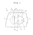
- the vehicular headlamp 1 includes a lamp housing 2 with a recessed section that opens to the front and a cover 3 that closes an opening of the lamp housing 2.
- a lamp outer box 4 is formed of the lamp housing 2 and the cover 3, and an internal space of the lamp outer box 4 constitutes a lamp chamber 5.
- An attachment hole 2a that penetrates in a front-rear direction is formed at a rear end portion of the lamp housing 2.
- a rear cover 6 is attached to the rear end portion of the lamp housing 2 to close the attachment hole 2a.
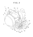
- a lamp unit 7 is disposed in the lamp chamber 5. As shown in FIG. 1 and FIG. 2 . the lamp unit 7 has a lens holder 8 that is positioned near a front end, a projection lens 9 that is held by the lens holder 8, a reflector 10 that is disposed behind the lens holder 8, a light source 11 that is disposed at a rear end of the reflector 10, and an attachment frame 12 to which predetermined components are attached.
- the lens holder 8 is formed of a holding section 8a having a generally circular shape and attachment sections 8b, 8b ... that protrude rearward respectively from the holding section 8a, and the attachment sections 8b, 8b...are provided to be spaced from each other in a circumferential direction.
- the projection lens 9 is held by the holding section 8a of the lens holder 8 and has a function of projecting light emitted by the light source 11 to irradiate the light externally.
- An inner surface of the reflector 10 is formed as a reflecting surface 10a.
- the attachment frame 12 is made of a plate material that is formed in a predetermined shape, and has, in an upper portion thereof, a light transmission hole 12a that penetrates in the front-rear direction. A portion below the light transmission hole 12a of the attachment frame 12 is provided as a fixed shade 13.
- First stoppers 12b, 12b are respectively provided at right and left ends of a center portion of the attachment frame 12 in a vertical direction
- second stoppers 12c, 12c are respectively provided at right and left ends of a lower end portion of the attachment frame 12 (see FIG. 2 and FIG. 3 ).
- Through holes 12d, 12d are respectively formed in positions between the first stoppers 12b, 12b and the second stopper 12c, 12c in the attachment frame 12, penetrating the attachment frame 12 in the front-rear direction.
- Movable shades 14, 14 that are pivotable with respect to the fixed shade 13 are pivotably supported on the attachment frame 12.
- the movable shades 14, 14 are arranged to be pivotable between a blocking position where the light emitted by the light source 11 is partially blocked and an unblocking position where the light emitted by the light source 11 is not blocked.
- the number of the movable shade that is supported on the attachment frame 12 may be one.
- the movable shade 14 is formed of a blocking section 15 that extends generally in a lateral direction, an actuated section 16 that protrudes generally downward from an outer end of the blocking section 15, and a restricted section 17 that protrudes generally in a lateral direction from the outer end of the blocking section 15.
- a pivot 14a is provided in a continuous portion between the blocking section 15 and the restricted section 17.
- the actuated section 16 is provided with a sliding protrusion 16a that is formed by bending an outer edge thereof to the front.
- the actuated section 16 is formed with an insertion locating hole 16b that penetrates in the front-rear direction in the vicinity of the sliding protrusion 16a.
- Shade drive mechanisms 18, 18 are respectively provided at right and left ends on a rear surface of the attachment frame 12.
- the shade drive mechanism 18 has a drive motor 19, a drive member 20 that is connected to a power output shaft 19a of the drive motor 19, and a return spring 21 that urges the drive member 20 in a predetermined direction (see FIG. 4 ).
- the drive motor 19 has a motor case 22 and a motor main body (not shown) that is disposed in the motor case 22, and the power output shaft 19a protrudes forward from the motor case 22.
- a spring engagement hole 22a is formed in a front surface of the motor case 22 is formed.
- the drive member 20 is provided between the movable shade 14 and the drive motor 19 and functions as a shade control means that controls a moving state (pivotal movement state) of the movable shade 14.
- the drive member 20 is formed of a base section 23 that faces in the front-rear direction, a connecting section 24 that protrudes rearward from a center portion of the base section 23, and actuating shafts 25, 25 that protrude forward from the base section 23.
- the base section 23 is provided with a spring engagement piece 23a that protrudes in the lateral direction.
- the actuating shafts 25, 25 are formed in a shape of a round shaft and provided on an outer peripheral side from the center portion of the base section 23 in a manner that the actuating shafts 25, 25 are spaced from each other in the circumferential direction.
- the connecting section 24 is connected to the power output shaft 19a, whereby the drive member 20 is rotated along with rotation of the drive motor 19.
- the return spring 21 is a coil spring, for example, and one end thereof is inserted in and engaged with the spring engagement hole 22a of the motor case 22 while the other end thereof is engaged with the spring engagement piece 23a of the base section 23.
- the drive member 20 is urged by the return spring 21 in an opposite direction from a direction that the drive member 20 is rotated along with the rotation of the drive motor 19.
- the drive member 20 is inserted through the through hole 12d of the attachment frame 12, and the actuating shafts 25, 25 are placed at opposite positions from each other with the sliding protrusions 16a of the movable shades 14 interposed therebetween (see FIG. 2 and FIG. 3 ).
- the one actuating shaft 25 is inserted in the insertion locating hole 16b.
- a low-beam radiation mode is set when both of the movable shades 14, 14 are in the blocking positions.
- the actuating shafts 25, 25 do not contact the sliding protrusion 16a (see FIG. 5 ).
- the drive member 20 is rotated at a predetermined angle, the one actuating shaft 25 comes into contact with the sliding protrusion 16a (see FIG. 6 ).
- the sliding protrusion 16a is pressed by the one actuating shaft 25, and the movable shade 14 is pivoted to the unblocking position (see FIG. 7 ).
- the one actuating shaft 25 is slid along the sliding protrusion 16a.
- a pivotal movement angle of the movable shade 14 from the blocking position to the unblocking position is set approximately from 10° to 30°, and a rotational angle of the drive motor 19 for this movement is set approximately 120°, for example.
- the movable shade 14 that is pivoted toward the unblocking position is restricted from being pivoted when the actuated section 16 comes into contact with the second stopper 12c of the attachment frame 12, and thus reaches the unblocking position.
- the movable shade 14 is held in the unblocking position by the continuous energization of the drive motor 19.
- a one-side high-beam radiation mode is set where either a right half or a left half of a light distribution pattern is a high-beam distribution pattern. Also, in a state where both of the movable shades 14, 14 are held in the unblocking positions (see FIG. 10 ), a high-beam radiation mode is set.
- the drive member 20 is rotated by the driving force of the drive motor 19. and the actuating shafts 25, 25 press the sliding protrusion 16a of the movable shade 14 within the rotational range of the drive member 20, that is, within part of the rotational range of the drive motor 19, to pivot the movable shade 14.
- the rotational angle of the drive motor 19 is set larger than the pivotal movement angle of the movable shade 14, it is possible to prevent pivotal movement failure, which can be caused by wear debris produced from a brush when the rotational angle of the drive motor 19 is set small, and thus, the durability of the drive motor 19 can be improved.
- a movable shade 14A is used.
- the movable shade 14A is formed of the blocking section 15 that extends generally in the lateral direction, an actuated section 16A that protrudes generally in the lateral direction from the outer end of the blocking section 15, and a restricted section 17A that protrudes generally downward from the outer end of the blocking section 15.
- the pivot 14a is provided in a continuous portion between the blocking section 15 and the actuated section 16A.
- a worm wheel section 16c is formed on an outer end of the actuated section 16A.
- the shade drive mechanisms 18A, 18A are respectively attached to the right and left ends on the rear surface of the attachment frame 12.
- the shade drive mechanism 18A has a drive motor 19A, a worm 26 that is connected to the power output shaft 19a of the drive motor 19A, and the return spring 21 that is supported on an upper end of the worm 26.
- the drive motor 19A includes a motor case 22A and a motor main body (not shown) that is disposed in the motor case 22A, and the power output shaft 19a protrudes upward from the motor case 22A.
- An upper surface of the motor case 22A is provided with a stopper pin 22b that protrudes upward.
- the worm 26 is provided between the movable shade 14A and the drive motor 19A, and functions as a shade control means that controls a moving state (pivotal movement state) of the movable shade 14A.
- the worm 26 is provided with, at the bottom end thereof, a stopper guide protrusion 26a that protrudes in the lateral direction.
- the worm 26 is connected to the power output shaft 19a and is rotated along with the rotation of the drive motor 19A.
- One end of the return spring 21 is engaged with a spring engagement section (not shown) of the attachment frame 12 while the other end thereof is engaged with a spring engagement protrusion (not shown) that is provided on the worm 26.
- the worm 26 is urged by the return spring 21 in an opposite direction from a direction that the worm 26 is rotated along with the rotation of the drive motor 19A.
- the worm 26 meshes with the worm wheel section 16c of the movable shade 14A.
- the restricted section 17A is pressed against and in contact with the first stoppers 12b of the attachment frame 12 by the urging force of the return springs 21 that is transmitted to the movable shade 14A via the worm 26.
- the movable shades 14A are in blocking position, the blocking section 15 extends in the horizontal direction, and thus a bottom end portion of the light transmission hole 12a is obstructed by the blocking section 15.
- the second stoppers 12c are not provided on the attachment frame 12.
- the gear ratio between the worm 26 and the worm wheel section 16c is set approximately 30:1, for example, and the movable shade 14A is pivoted at a significantly lower speed as compared to a speed at which the worm 26 is rotated.
- the movable shade 14A that is pivoted toward the unblocking position is restricted from being pivoted when the stopper guide protrusion 26a of the worm 26 comes into contact with the stopper pin 22b provided on the motor case 22A, and thus reaches the unblocking position.
- the movable shade 14A is held in the unblocking position by the continuous energization of the drive motor 19A.
- the shade drive mechanism 18A is configured such that the stopper pin 22b and the stopper guide protrusion 26a are provided to restrict the rotation of the worm 26 and thus the movable shade 14A is pivoted from the blocking position to the unblocking position.
- the gear teeth of the worm 26 are less likely to be caught in the worm wheel section 16c, and thus the smooth operations of the worm 26 and the movable shade 14A is assured.
- the movable shade 14A is pivoted by using the worm 26, and the reduction gear is not used. Therefore, it is possible to prevent a defect such as failure in movement of the movable shade caused by the decreased durability of the gear teeth resulted from the acquisition of the high reduction gear ratio. This is useful for maintaining the favorable moving state of the movable shade 14A.
- the movable shade 14B is formed of the blocking section 15 that extends generally in the lateral direction and an actuated section 16B that protrudes generally downward from the outer end of the blocking section 15.
- the pivot 14a is provided in a continuous portion between the blocking section 15 and the actuated section 16B.
- a spring engagement protrusion 15a is provided on the blocking section 15 of the movable shade 14B in a position near the actuated section 16B.
- a driven gear section 16d is formed on an outer end of the actuated section 16B.
- the attachment frame 12 is provided with the first stoppers 12b, 12b on its lower side and the second stoppers 12c, 12c on its upper side.
- the attachment frame 12 is also provided with spring support pieces 12e, 12e near the second stoppers 12c, 12c.
- the shade drive mechanisms 18B, 18B are attached to the right and left ends on the rear surface of the attachment frame 12.
- the shade drive mechanism 18B has a drive motor 19B, an overdrive gear 27 that is connected to the power output shaft 19a of the drive motor 19B, a flywheel 28 that meshes with the overdrive gear 27, and the return spring 21 that is supported by the pivot 14a of the movable shade 14B.
- the drive motor 19B has a motor case 22B and the motor main body (not shown) that is disposed in the motor case 22B, and the power output shaft 19a protrudes toward the front from the motor case 22B.
- the overdrive gear 27 and the flywheel 28 are provided between the movable shade 14B and the drive motor 19B and function as the shade control means that control a moving state (pivotal movement state) of the movable shade 14B.
- the overdrive gear 27 is provided such that a first gear section 27a located on the rear side and a second gear section 27b having a larger diameter than the first gear section 27a and located on the front side are coaxially arranged.
- the flywheel 28 is provided such that a weighted section 29 located on the front side and a transmission gear section 30 located on the rear side are coaxially arranged, and is rotatably supported by the attachment frame 12 via a support shaft 31.
- a diameter of the transmission gear section 30 of the flywheel 28 is set smaller than a diameter of the second gear section 27b of the overdrive gear 27.
- the transmission gear section 30 meshes with the second gear section 27b of the overdrive gear 27.
- the overdrive gear 27 is connected to the power output shaft 19a, and the overdrive gear 27 and the flywheel 28 are rotated along with the rotation of the drive motor 19B.
- One end of the return spring 21 engages with the spring support piece 12e of the attachment frame 12 while the other end thereof engages with the spring engagement protrusion 15a that is provided on the movable shade 14B.
- the movable shade 14B is urged by the return spring 21 in an opposite direction from a direction that the movable shade 14B is pivoted along with the rotation of the drive motor 19B.
- the actuated section 16B of the movable shade 14B is pressed against and in contact with the first stopper 12b of the attachment frame 12 by the urging force of the return spring 21. At this time, the movable shade 14B is in the blocking position, the blocking section 15 extends in the horizontal direction, and thus the bottom end portion of the light transmission hole 12a is obstructed by the blocking section 15.
- the overdrive gear 27 When the overdrive gear 27 is rotated, the driven gear section 16d is advanced, and the movable shade 14B is pivoted toward the unblocking position. At this time, the gear ratio between the driven gear section 16d of the movable shade 14B and the first gear section 27a of the overdrive gear 27 is set approximately 7:1 to 10:1. and the movable shade 14B is pivoted at significantly reduced speed with respect to the rotation of the drive motor 19B.
- the movable shade 14B that has been pivoted toward the unblocking position is restricted from being pivoted when the actuated section 16B comes into contact with the second stopper 12c of the attachment frame 12, and thus reaches the unblocking position.
- the movable shade 14B is held in the unblocking position by the continuous energization of the drive motor 19B.
- the movable shade 14B is pivoted by transmitting the power of the flywheel 28 in the vehicular headlamp 1 that is provided with the shade drive mechanism 18B, and thus the moving speed (pivotal movement speed) of the movable shade 14B is decreased, reducing the impact generated when the movable shade 14B contacts the first stopper 12b and the second stopper 12c. Therefore, the favorable moving state of the movable shade 14B can be secured.
- the radiation mode is not switched instantly, and thus it is possible to suppress the occurrence of a sense of discomfort to a driver.
- a flywheel 28B which will be described below, may be used instead of the flywheel 28 (see FIG. 13 to FIG. 16 ).
- the weighted section 29B is rotatably supported by the transmission gear section 30B via the support shaft 31 (see FIG. 13 ).
- Actuated protrusions 29a, 29a that protrude rearward are provided on a rear surface of the weighted section 29B, and the actuated protrusions 29a, 29a are positioned oppositely from each other at 180° on the same radius in reference to the center axis of the weighted section 29B.
- a spring engagement shaft 29b that protrudes rearward is provided on the rear surface of the weighted section 29B in a position closer to the outer peripheral side than the actuated protrusions 29a, 29a.
- the transmission gear section 30B is constructed such that a gear body 32 and an actuating body 33 that protrudes toward the front from the gear body 32 are formed integrally.
- the actuating body 33 is formed of a central shaft section 33a that protrudes toward the front from the center portion of the gear body 32 and a pair of actuating sections 33b, 33b that protrude laterally from the central shaft section 33a in opposite directions from each other.
- the actuating body 33 is provided with a spring engagement shaft section 33c that protrudes laterally from the one actuating section 33b.
- a twisted coil spring 34 is supported therebetween.
- a coil section 34a of the twisted coil spring 34 is fitted onto and supported by the actuating body 33, and one end 34b engages with the spring engagement shaft 29b of the weighted section 29B while the other end 34c engages with a spring engagement shaft section 33c of the transmission gear section 30B.
- the weighted section 29B is urged by the twisted coil spring 34 in an opposite direction from a direction that the weighted section 29B is rotated along with the rotation of the drive motor 19B.
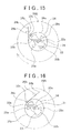
- the flywheel 28B When the movable shade 14B is pivoted from the blocking position to the unblocking position, the flywheel 28B is in the state where the actuated protrusions 29a, 29a of the weighted section 29B are respectively in contact with the actuating sections 33b, 33b of the transmission gear section 30B, and pressed against the actuating sections 33b, 33b, and thus the weighted section 29B and the transmission gear section 30B are integrally rotated clockwise when seen from rear (see FIG. 14 ).
- flywheel 28B As described above, when the movable shade 14B is pivoted from the blocking position to the unblocking position, the flywheel 28B keeps being rotated and the rotational speed thereof gradually decreases. Therefore, it is possible to sufficiently mitigate the impact at the time when the movable shade 14B comes into contact with the second stopper 12c and is pivoted to the unblocking position.
- the movable shade 14C is formed of the blocking section 15 that extends generally in the lateral direction and an actuated section 16C that protrudes generally downward from the outer end of the blocking section 15. and the pivot 14a is provided in a continuous portion between the blocking section 15 and the actuated section 16C.
- a driven gear section 16e is formed in the bottom end portion of ⁇ the actuated section 16C.
- the actuated section 16C is provided with a spring engagement protrusion 16f.
- the attachment frame 12 is provided with first stoppers 12b, 12b and second stoppers 12c, 12c that are spaced from each other in the lateral direction with the actuated section 16C disposed therebetween.
- the attachment frame 12 is also provided with spring support pieces 12e, 12e.
- the shade drive mechanisms 18C, 18C are respectively provided at the right and left ends on the rear surface of the attachment frame 12.
- the shade drive mechanism 18C has a drive motor 19C, a drive unit 35, and the return spring 21.
- the drive motor 19C has a motor case 22C and a motor body (not shown) that is disposed in the motor case 22C, and the power output shaft 19a protrudes forward from the motor case 22C.
- the drive unit 35 is formed of a case body 36 that meshes with a driven gear section 16e of the movable shade 14C, a rotary drive body 37 that is rotatably supported by the case body 36 and is connected to the power output shaft 19a of the drive motor 19C, and a spiral spring 38 that is disposed inside the case body 36.
- the drive unit 35 is provided between the movable shade 14C and the drive motor 19C and functions as a shade control means that controls a moving state (pivotal movement state) of the movable shade 14C.
- the case body 36 is formed of a case section 36a that opens to the front and a drive gear section 36b that protrudes rearward from a rear surface of the case section 36a.
- the drive gear section 36b meshes with the driven gear section 16e of the movable shade 14C.
- the rotary drive body 37 is formed of a connecting plate section 37a having a circular disc shape and a supported shaft section 37b that protrudes forward from a center portion of the connecting plate section 37a, and the supported shaft section 37b is inserted through the case body 36 from the rear and is rotatable supported by the case body 36.
- a front end of the supported shaft section 37b is located inside the case section 36a of the case body 36.
- a center portion of the connecting plate section 37a in the rotary drive body 37 is connected to the power output shaft 19a of the drive motor 19C.
- spiral spring 38 is connected to the outer periphery of the case section 36a of the case body 36 while the other end thereof is connected to the front end of the supported shaft section 37b of the rotary drive body 37 that is positioned inside the case section 36a.
- One end of the return spring 21 engages with the spring support piece 12e of the attachment frame 12, while the other end thereof engages with the spring engagement protrusion 16f provided on the movable shade 14C.
- the movable shade 14C is urged by the return spring 21 in an opposite direction from a direction that the movable shade 14C is pivoted along with the rotation of the drive motor 19C.
- the actuated section 16C of the movable shade 14C is pressed against and in contact with the first stopper 12b of the attachment frame 12 by the urging force of the return spring 21. At this time, the movable shade 14C is in the blocking position, the blocking section 15 extends in the horizontal direction, and thus the bottom end portion of the light transmission hole 12a is obstructed by the blocking sections 15.
- the rotary drive body 37 of the drive unit 35 is rotated along with the rotation of the drive motor 19C against the urging force of the return spring 21.
- the spiral spring 38 is winded in a direction that a diameter thereof becomes smaller, and the case body 36 is rotated along with the winding of the spiral spring 38.
- the driven gear section 16e When the case body 36 is rotated, the driven gear section 16e is advanced, and the movable shade 14C is pivoted toward the unblocking position. At this time, the gear ratio between the driven gear section 16e of the movable shade 14C and the drive gear section 36b of the case body 36 is set approximately 7:1 to 10:1, for example, and thus the movable shade 14C is pivoted at significantly reduced speed with respect to the rotation of the drive motor 19C.
- the rotational speed of the case body 36 is lower than the rotational speed of the rotary drive body 37, and thus the movable shade 14C is pivoted at low speed.
- the movable shade 14C that has been pivoted toward the unblocking position is restricted from being pivoted when the actuated section 16C comes into contact with the second stopper 12c of the attachment frame 12, and thus reaches the unblocking position.
- the movable shade 14C is held in the unblocking position by the continuous energization of the drive motor 19C.
- the pivotal movement of the movable shade 14C is restricted when the actuated section 16C comes into contact with the first stopper 12b of the attachment frame 12, and is held in the blocking position.
- the moving speed (pivotal movement speed) of the movable shade 14C is decreased, and thus the impact caused by the contact between the movable shade 14C and the second stopper 12c is mitigated. Therefore, the favorable moving state of the movable shade 14C can be maintained.
- the radiation mode is not switched instantly, and thus it is possible to suppress the occurrence of a sense of discomfort to a driver.
- the moving states of the movable shades 14, 14A, 14B, 14C are controlled respectively by the shade control means, it is possible to moderate the moving state of the movable shades 14, 14A, 14B, 14C.
Landscapes
- Engineering & Computer Science (AREA)
- General Engineering & Computer Science (AREA)
- Mechanical Engineering (AREA)
- Non-Portable Lighting Devices Or Systems Thereof (AREA)
Abstract
Description
- The present invention relates to a vehicular headlamp. More specifically, the present invention relates to a vehicular headlamp that can achieve various radiation modes by changing a blocking state of light with a movable shade.
- An example of a vehicular headlamp is one in which a lamp unit with a light source is disposed in an outer box of a lamp that is formed of a cover and a lamp housing.
- The lamp unit is provided with a projection lens that projects, to the front, light emitted by the light source and a reflector that reflects, toward the projection lens, the light emitted by the light source.
- As a vehicular headlamp such as above, there is one that includes a fixed shade that partially blocks the light emitted by the light source and a movable shade that is movable with respect to the fixed shade and can partially block the light emitted by the light source (for example, see Japanese Patent Application Publication No.
2010-257909 JP 2010-257909 A 2010-40459 JP 2010-40459 A - Vehicular headlamps that are disclosed in
JP 2010-257909 A JP 2010-40459 A - However, in the vehicular headlamp such as above, in which the movable shade is moved by the driving force of the drive motor, there is a possibility that deterioration in a moving state of the movable shade occurs, depending on a state of the transmission of the driving force from the drive motor to the movable shade.
- For example, for the purpose of improving durability of the drive motor, there is a case where it is desired to set a pivotal movement angle of the movable shade smaller than a rotational angle of the drive motor. If a reduction gear is used to increase a reduction gear ratio in such a case, a gear module needs to be downsized or plural gears are needed, and consequently, the reduced durability of gear teeth may cause deterioration in the moving state of the movable shade.
- Meanwhile, a vehicular headlamp has been available that is configured to restrict the movement of the movable shade by a stopper provided in a predetermined position. In such a vehicular headlamp, for example, when a moving speed of the movable shade becomes too fast due to the transmission state of the driving force of the drive motor, the movable shade contacts the stopper with a large force, and consequently, there is a possibility that deterioration in the moving state of the movable shade occurs.
- In addition, if the moving speed of the movable shade is too fast, it may cause application of a powerful impact between the gear teeth or cause wear of the members, especially at the beginning of the movement, and consequently, the moving state of the movable shade may become unstable.
- An object of the present invention is to provide a vehicular headlamp in which a moving state of a movable shade can be moderated.
- The vehicular headlamp according to an aspect of the present invention includes: a light source that emits light; a reflector that reflects the light emitted by the light source; a projection lens that projects and irradiates the light emitted by the light source; a fixed shade that partially blocks the light emitted by the light source; a movable shade that is movable with respect to the fixed shade and is capable of partially blocking the light emitted by the light source; a drive motor that moves the movable shade; shade control means that is provided between the movable shade and the drive motor and is configured to control a moving state of the movable shade.
- Because the driving force of the drive motor is transmitted to the movable shade with the moving state of the movable shade controlled by the shade control means, it is possible to moderate the moving state of the movable shade.
- In the vehicular headlamp according to the above aspect, it is preferable that the shade control means be speed change control means connecting between the movable shade and the drive motor and configured to suppress rapid change in speed of movement of the movable shade when the movable shade starts to be moved by the drive motor.
- The rapid change in speed of movement of the movable shade when the movable shade starts to be moved by the drive motor is suppressed, the radiation mode is not switched instantly, and thus it is possible to suppress the occurrence of a sense of discomfort to a driver.
- In the vehicular headlamp according to the above aspect, it is preferable that the speed change control means be configured to suppress the rapid change in speed of movement via a mechanical structure.
- In the vehicular headlamp according to the above aspect, it is preferable that the speed change control means include a rotary body that is rotated by the drive motor, the rotary body having an actuating shaft that is positioned so as to be offset from a center of rotation of the rotary body, and the speed change control means be configured such that a direction of movement of the actuating shaft and a direction of movement of the point of contact between the actuating shaft and the movable shade form an angle between 45° and 90° inclusive when the movable shade starts to be moved by the drive motor.
- According to the above configuration, it is possible to reduce the amount of movement of the movable shade corresponding to the same rotational angle of the actuating shaft when the movable shade starts to be moved by the drive motor, so that it is possible to suppress the rapid change in speed of movement of the movable shade.
- In the vehicular headlamp according to the above aspect, it is preferable that the shade control means include a drive member that has a connecting section connected to a power output shaft of the drive motor and an actuating shaft located on an outer peripheral side of the power output shaft and projecting from the connecting section, and that the drive member be rotated by the driving force of the drive motor and that the actuating shaft press the movable shade within a part of a rotational range of the drive member and move the movable shade.
- According to the above configuration, the movable shade can be moved by a small angle with respect to a rotational angle of the drive motor without use of a reduction gear, so that a defect can be prevented such as failure in movement of the movable shade, which can be caused by reduced durability of the gear teeth when the reduction gear is used, and the favorable moving state of the movable shade can be ensured.
- In the vehicular headlamp according to the above aspect, it is preferable that the movable shade is provided with a worm wheel section and that the shade control means include a worm that is connected to the power output shaft of the drive motor.
- According to the above configuration, because the movable shade is moved by the worm and the reduction gear is not used, it is possible to prevent a defect such as failure in movement of the movable shade, which can be caused by reduced durability of the gear teeth when large reduction gear ratio is obtained using the reduction gear, and the favorable moving state of the movable shade is ensured.
- In the vehicular headlamp according to the above aspect, it is preferable that the speed change control means be configured to suppress the rapid change in speed of movement using inertia.
- In the vehicular headlamp according to the above aspect, it is preferable that a driven gear section be provided on the movable shade and that the shade control means include a flywheel having a transmission gear section, and an overdrive gear that has a first gear section connected to the power output shaft of the drive motor and meshing with the driven gear section of the movable shade and a second gear section meshing with the transmission gear section of the flywheel.
- According to the above aspect, because the movable shade is moved by transmitting power of the flywheel, a moving speed of the movable shade is decreased, and thus the movable shade is moved at low speed. Therefore, the favorable moving state of the movable shade can be ensured.
- In the vehicular headlamp according to the above aspect, it is preferable that the speed change control means be configured to suppress the rapid change in speed of movement by transmitting a driving force from the drive motor to the movable shade via an elastic body.
- In the vehicular headlamp according to the above aspect, it is preferable that the elastic body be a spiral spring.
- In the vehicular headlamp according to the above aspect, it is preferable that the movable shade be provided with the driven gear section and that the shade control means include a case body that has a drive gear section meshing with the driven gear section, a rotary drive body that is connected to the power output shaft of the drive motor and is rotated with respect to the case body along with the rotation of the drive motor, and a spiral spring, one end of which is connected to the case body and the other end of which is connected to the rotary drive body.
- According to the above configuration, the moving speed of the movable shade is decreased, and thus the movable shade is moved at low speed. Therefore, the favorable moving state of the movable shade can be ensured.
- Features, advantages, and technical and industrial significance of exemplary embodiments of the invention will be described below with reference to the accompanying drawings, in which like numerals denote like elements, and wherein:
-
FIG. 1 shows a vehicular headlamp of an embodiment of the present invention together withFIG. 2 to FIG. 18 and is a schematic longitudinal sectional view of the vehicular headlamp; -
FIG. 2 is a perspective view of a lamp unit; -
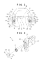
FIG. 3 is a schematic front view that shows a state where a movable shade is in a blocking position; -
FIG. 4 is an enlarged exploded perspective view of a shade drive mechanism; -
FIG. 5 shows operation of a drive member together withFIG. 6 andFIG. 7 and is an enlarged front view that shows a state where an actuating shaft is not in contact with a sliding protrusion of the movable shade when a drive member is rotated; -
FIG. 6 is an enlarged front view that shows a state where the actuating shaft is in contact with the sliding protrusion of the movable shade when the drive member is rotated; -
FIG. 7 is an enlarged front view that shows a state where the actuating shaft is in contact with the sliding protrusion of the movable shade when the drive member is rotated and the movable shade is pivoted; -
FIG. 8 is a schematic front view that shows a state where one movable shade is pivoted to an unblocking position; -
FIG. 9 is a schematic front view that shows a state where another movable shade is pivoted to an unblocking position; -
FIG. 10 is a schematic front view that shows a state where both of the movable shades are pivoted to the unblocking positions; -
FIG. 11 is a schematic front view that shows the shade drive mechanism and the movable shade according to a first modification; -
FIG. 12 is a schematic front view that shows the shade drive mechanism and so on according to a second modification; -
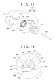
FIG. 13 shows, together withFIG. 14 to FIG. 16 , a configuration of the shade drive mechanism according to the second modification in which a weighted section and a transmission gear section are separated, and is an exploded perspective view; -
FIG. 14 is a schematic rear view that shows a relationship between an actuated protrusion and an actuating section when the weighted section and the transmission gear section are integrally rotated; -
FIG. 15 is a schematic rear view that shows a relationship between the actuated protrusion and the actuating section, followingFIG. 14 , when the weighted section is rotated while the transmission gear stops being rotated; -
FIG. 16 is a schematic rear view that shows a relationship between the actuated protrusion and the actuating section, followingFIG. 15 , when the weighted section stops being rotated; -
FIG. 17 shows, together withFIG. 18 , a shade drive mechanism according to a third modification and is a schematic front view that shows the shade drive mechanism and the movable shade; and -
FIG. 18 is a schematic sectional view that shows the shade drive mechanism and the movable shade. - Description will hereinafter be made of an embodiment of a vehicular headlamp according to the present invention with reference to the attached drawings.
- A vehicular headlamp 1 is attached to and disposed at each of right and left ends on a front end of a vehicle. The words/phrases representing directions, such as right, left, front, rear, above, below, vertical, lateral, etc. herein means directions in relation to the vehicle, or the vehicular lamp mounted on the vehicle.
- As shown in
FIG. 1 , the vehicular headlamp 1 includes alamp housing 2 with a recessed section that opens to the front and acover 3 that closes an opening of thelamp housing 2. A lampouter box 4 is formed of thelamp housing 2 and thecover 3, and an internal space of the lampouter box 4 constitutes alamp chamber 5. - An attachment hole 2a that penetrates in a front-rear direction is formed at a rear end portion of the
lamp housing 2. A rear cover 6 is attached to the rear end portion of thelamp housing 2 to close the attachment hole 2a. - A
lamp unit 7 is disposed in thelamp chamber 5. As shown inFIG. 1 andFIG. 2 . thelamp unit 7 has alens holder 8 that is positioned near a front end, aprojection lens 9 that is held by thelens holder 8, areflector 10 that is disposed behind thelens holder 8, alight source 11 that is disposed at a rear end of thereflector 10, and anattachment frame 12 to which predetermined components are attached. - The
lens holder 8 is formed of aholding section 8a having a generally circular shape andattachment sections section 8a, and theattachment sections - The
projection lens 9 is held by the holdingsection 8a of thelens holder 8 and has a function of projecting light emitted by thelight source 11 to irradiate the light externally. - An inner surface of the
reflector 10 is formed as a reflectingsurface 10a. - The
attachment frame 12 is made of a plate material that is formed in a predetermined shape, and has, in an upper portion thereof, alight transmission hole 12a that penetrates in the front-rear direction. A portion below thelight transmission hole 12a of theattachment frame 12 is provided as a fixedshade 13. -
First stoppers attachment frame 12 in a vertical direction, andsecond stoppers FIG. 2 andFIG. 3 ). Throughholes first stoppers second stopper attachment frame 12, penetrating theattachment frame 12 in the front-rear direction. -
Movable shades shade 13 are pivotably supported on theattachment frame 12. Themovable shades light source 11 is partially blocked and an unblocking position where the light emitted by thelight source 11 is not blocked. - It is noted that the number of the movable shade that is supported on the
attachment frame 12 may be one. - The
movable shade 14 is formed of ablocking section 15 that extends generally in a lateral direction, an actuatedsection 16 that protrudes generally downward from an outer end of the blockingsection 15, and a restrictedsection 17 that protrudes generally in a lateral direction from the outer end of the blockingsection 15. Apivot 14a is provided in a continuous portion between the blockingsection 15 and the restrictedsection 17. - The actuated
section 16 is provided with a slidingprotrusion 16a that is formed by bending an outer edge thereof to the front. The actuatedsection 16 is formed with aninsertion locating hole 16b that penetrates in the front-rear direction in the vicinity of the slidingprotrusion 16a. - Shade drive
mechanisms attachment frame 12. Theshade drive mechanism 18 has adrive motor 19, adrive member 20 that is connected to apower output shaft 19a of thedrive motor 19, and areturn spring 21 that urges thedrive member 20 in a predetermined direction (seeFIG. 4 ). - The
drive motor 19 has amotor case 22 and a motor main body (not shown) that is disposed in themotor case 22, and thepower output shaft 19a protrudes forward from themotor case 22. Aspring engagement hole 22a is formed in a front surface of themotor case 22 is formed. - The
drive member 20 is provided between themovable shade 14 and thedrive motor 19 and functions as a shade control means that controls a moving state (pivotal movement state) of themovable shade 14. - The
drive member 20 is formed of abase section 23 that faces in the front-rear direction, a connectingsection 24 that protrudes rearward from a center portion of thebase section 23, andactuating shafts base section 23. Thebase section 23 is provided with aspring engagement piece 23a that protrudes in the lateral direction. Theactuating shafts base section 23 in a manner that theactuating shafts - The connecting
section 24 is connected to thepower output shaft 19a, whereby thedrive member 20 is rotated along with rotation of thedrive motor 19. - The
return spring 21 is a coil spring, for example, and one end thereof is inserted in and engaged with thespring engagement hole 22a of themotor case 22 while the other end thereof is engaged with thespring engagement piece 23a of thebase section 23. - The
drive member 20 is urged by thereturn spring 21 in an opposite direction from a direction that thedrive member 20 is rotated along with the rotation of thedrive motor 19. - In a state where the
shade drive mechanism 18 is attached to the rear surface of theattachment frame 12, thedrive member 20 is inserted through the throughhole 12d of theattachment frame 12, and theactuating shafts protrusions 16a of themovable shades 14 interposed therebetween (seeFIG. 2 andFIG. 3 ). The oneactuating shaft 25 is inserted in theinsertion locating hole 16b. - In a state where the
drive motor 19 is not energized, the restrictedsections movable shades first stoppers attachment frame 12 by the urging forces of the return springs 21, 21 (seeFIG. 3 ). At this time, themovable shades sections light transmission hole 12a is obstructed by the blockingsections other actuating shaft 25 of thedrive member 20 is in contact with the slidingprotrusion 16a. - A low-beam radiation mode is set when both of the
movable shades - When the
drive motor 19 is energized and thedrive motor 19 begins to be rotated in a state where themovable shade 14 is in the blocking position, thedrive member 20 is rotated along with the rotation of thedrive motor 19 against the urging force of thereturn spring 21. - Within a given rotational range of the
drive member 20, theactuating shafts protrusion 16a (seeFIG. 5 ). When thedrive member 20 is rotated at a predetermined angle, the oneactuating shaft 25 comes into contact with the slidingprotrusion 16a (seeFIG. 6 ). When thedrive member 20 keeps being rotated, the slidingprotrusion 16a is pressed by the oneactuating shaft 25, and themovable shade 14 is pivoted to the unblocking position (seeFIG. 7 ). At this time, the oneactuating shaft 25 is slid along the slidingprotrusion 16a. - In the vehicular headlamp 1, a pivotal movement angle of the
movable shade 14 from the blocking position to the unblocking position is set approximately from 10° to 30°, and a rotational angle of thedrive motor 19 for this movement is set approximately 120°, for example. - The
movable shade 14 that is pivoted toward the unblocking position is restricted from being pivoted when the actuatedsection 16 comes into contact with thesecond stopper 12c of theattachment frame 12, and thus reaches the unblocking position. Themovable shade 14 is held in the unblocking position by the continuous energization of thedrive motor 19. - When the
drive motor 19 stops being energized in a state where themovable shade 14 is in the unblocking position, thedrive member 20 is rotated in the direction opposite to the previous direction by the urging force of thereturn spring 21. Then, the slidingprotrusion 16a is pressed by theother actuating shaft 25 within the predetermined rotational range of thedrive member 20, and themovable shade 14 is pivoted toward the blocking position. Themovable shade 14 is restricted from being pivoted when the restrictedsection 17 comes into contact with thefirst stopper 12b of theattachment frame 12, and thus is held in the blocking position. - In the vehicular headlamp I, in a state where the one
movable shade 14 is held in the blocking position while the othermovable shade 14 is held in the unblocking position (seeFIG. 8 and FIG. 9 ), a one-side high-beam radiation mode is set where either a right half or a left half of a light distribution pattern is a high-beam distribution pattern. Also, in a state where both of themovable shades FIG. 10 ), a high-beam radiation mode is set. - As described above, in the vehicular headlamp 1 that is provided with the
shade drive mechanisms drive member 20 is rotated by the driving force of thedrive motor 19. and theactuating shafts protrusion 16a of themovable shade 14 within the rotational range of thedrive member 20, that is, within part of the rotational range of thedrive motor 19, to pivot themovable shade 14. - Accordingly, it is possible without using a reduction gear to pivot the
movable shade 14 at a smaller angle than the rotational angle of thedrive motor 19, and thus it is possible to prevent a defect such as failure in movement of a movable shade, which can be caused by the decreased durability of gear teeth when the reduction gear is used. Therefore, the favorable moving state of themovable shade 14 is ensured. - In addition, because the rotational angle of the
drive motor 19 is set larger than the pivotal movement angle of themovable shade 14, it is possible to prevent pivotal movement failure, which can be caused by wear debris produced from a brush when the rotational angle of thedrive motor 19 is set small, and thus, the durability of thedrive motor 19 can be improved. - Next, a description will be made of each modification of the shade drive mechanism (see
FIG. 11 to FIG. 18 ). It should be noted that, when a shade drive mechanism according to any of modifications below is used instead of theshade drive mechanism 18 described above, the vehicular headlamp 1 mainly differ in, in addition to the shade drive mechanism, only the constructions of the movable shade and the drive motor. Therefore, only the differences in the constructions of the shade drive mechanism, the movable shade, and so on are explained in detail in the following description of each modification while the other components that have already been described are denoted by the same reference numerals, and thus detailed description thereof will not be repeated. - First, a description will be made of a
shade drive mechanism 18A according to a first modification (seeFIG. 11 ). - When the
shade drive mechanism 18A according to the first modification is used, amovable shade 14A is used. - The
movable shade 14A is formed of the blockingsection 15 that extends generally in the lateral direction, an actuatedsection 16A that protrudes generally in the lateral direction from the outer end of the blockingsection 15, and arestricted section 17A that protrudes generally downward from the outer end of the blockingsection 15. Thepivot 14a is provided in a continuous portion between the blockingsection 15 and the actuatedsection 16A. - A
worm wheel section 16c is formed on an outer end of the actuatedsection 16A. - The
shade drive mechanisms attachment frame 12. Theshade drive mechanism 18A has adrive motor 19A, aworm 26 that is connected to thepower output shaft 19a of thedrive motor 19A, and thereturn spring 21 that is supported on an upper end of theworm 26. - The
drive motor 19A includes amotor case 22A and a motor main body (not shown) that is disposed in themotor case 22A, and thepower output shaft 19a protrudes upward from themotor case 22A. An upper surface of themotor case 22A is provided with astopper pin 22b that protrudes upward. - The
worm 26 is provided between themovable shade 14A and thedrive motor 19A, and functions as a shade control means that controls a moving state (pivotal movement state) of themovable shade 14A. - The
worm 26 is provided with, at the bottom end thereof, astopper guide protrusion 26a that protrudes in the lateral direction. Theworm 26 is connected to thepower output shaft 19a and is rotated along with the rotation of thedrive motor 19A. - One end of the
return spring 21 is engaged with a spring engagement section (not shown) of theattachment frame 12 while the other end thereof is engaged with a spring engagement protrusion (not shown) that is provided on theworm 26. Theworm 26 is urged by thereturn spring 21 in an opposite direction from a direction that theworm 26 is rotated along with the rotation of thedrive motor 19A. Theworm 26 meshes with theworm wheel section 16c of themovable shade 14A. - When the
drive motor 19A is not energized, the restrictedsection 17A is pressed against and in contact with thefirst stoppers 12b of theattachment frame 12 by the urging force of the return springs 21 that is transmitted to themovable shade 14A via theworm 26. At this time, themovable shades 14A are in blocking position, the blockingsection 15 extends in the horizontal direction, and thus a bottom end portion of thelight transmission hole 12a is obstructed by the blockingsection 15. - When the
shade drive mechanism 18A is used, thesecond stoppers 12c are not provided on theattachment frame 12. - When the
drive motor 19A is energized and thedrive motor 19A begins to be rotated in a state where themovable shade 14A is in the blocking position, theworm 26 is rotated along with the rotation of thedrive motor 19A against the urging force of thereturn spring 21. - When the
worm 26 is rotated, theworm wheel section 16c is advanced, and themovable shade 14A is pivoted toward the unblocking position. At this time, the gear ratio between theworm 26 and theworm wheel section 16c is set approximately 30:1, for example, and themovable shade 14A is pivoted at a significantly lower speed as compared to a speed at which theworm 26 is rotated. - The
movable shade 14A that is pivoted toward the unblocking position is restricted from being pivoted when thestopper guide protrusion 26a of theworm 26 comes into contact with thestopper pin 22b provided on themotor case 22A, and thus reaches the unblocking position. Themovable shade 14A is held in the unblocking position by the continuous energization of thedrive motor 19A. - When the
drive motor 19A stops being energized in a state where themovable shade 14A is in the unblocking position, theworm 26 is rotated in the direction opposite to the previous direction by the urging force of thereturn spring 21. and themovable shade 14A is pivoted toward the blocking position. When the restrictedsection 17A comes into contact with thefirst stoppers 12b of theattachment frame 12, themovable shade 14A is restricted from being pivoted and thus is held in the blocking position. - The
shade drive mechanism 18A is configured such that thestopper pin 22b and thestopper guide protrusion 26a are provided to restrict the rotation of theworm 26 and thus themovable shade 14A is pivoted from the blocking position to the unblocking position. - Therefore, as compared to a case where the
movable shade 14A is partially brought into contact with the stopper to restrict the pivotal movement of themovable shade 14A during the rotation of thedrive motor 19A, the gear teeth of theworm 26 are less likely to be caught in theworm wheel section 16c, and thus the smooth operations of theworm 26 and themovable shade 14A is assured. - As described above, in the vehicular headlamp 1 that is provided with the
shade drive mechanism 18A, themovable shade 14A is pivoted by using theworm 26, and the reduction gear is not used. Therefore, it is possible to prevent a defect such as failure in movement of the movable shade caused by the decreased durability of the gear teeth resulted from the acquisition of the high reduction gear ratio. This is useful for maintaining the favorable moving state of themovable shade 14A. - Furthermore, because the
movable shade 14A is pivoted by using theworm 26, reduction in size can be achieved. - Next, a description will be made of a
shade drive mechanism 18B according to a second modification (seeFIG. 12 ). - When the
shade drive mechanism 18B according to the second modification is used, amovable shade 14B is used. - The
movable shade 14B is formed of the blockingsection 15 that extends generally in the lateral direction and an actuatedsection 16B that protrudes generally downward from the outer end of the blockingsection 15. Thepivot 14a is provided in a continuous portion between the blockingsection 15 and the actuatedsection 16B. Aspring engagement protrusion 15a is provided on the blockingsection 15 of themovable shade 14B in a position near the actuatedsection 16B. - A driven
gear section 16d is formed on an outer end of the actuatedsection 16B. - When the
shade drive mechanism 18B is used, theattachment frame 12 is provided with thefirst stoppers second stoppers attachment frame 12 is also provided withspring support pieces second stoppers - The
shade drive mechanisms attachment frame 12. Theshade drive mechanism 18B has adrive motor 19B, anoverdrive gear 27 that is connected to thepower output shaft 19a of thedrive motor 19B, aflywheel 28 that meshes with theoverdrive gear 27, and thereturn spring 21 that is supported by thepivot 14a of themovable shade 14B. - The
drive motor 19B has amotor case 22B and the motor main body (not shown) that is disposed in themotor case 22B, and thepower output shaft 19a protrudes toward the front from themotor case 22B. - The
overdrive gear 27 and theflywheel 28 are provided between themovable shade 14B and thedrive motor 19B and function as the shade control means that control a moving state (pivotal movement state) of themovable shade 14B. - The
overdrive gear 27 is provided such that afirst gear section 27a located on the rear side and asecond gear section 27b having a larger diameter than thefirst gear section 27a and located on the front side are coaxially arranged. - The
flywheel 28 is provided such that aweighted section 29 located on the front side and atransmission gear section 30 located on the rear side are coaxially arranged, and is rotatably supported by theattachment frame 12 via asupport shaft 31. A diameter of thetransmission gear section 30 of theflywheel 28 is set smaller than a diameter of thesecond gear section 27b of theoverdrive gear 27. In theflywheel 28, thetransmission gear section 30 meshes with thesecond gear section 27b of theoverdrive gear 27. - The
overdrive gear 27 is connected to thepower output shaft 19a, and theoverdrive gear 27 and theflywheel 28 are rotated along with the rotation of thedrive motor 19B. - One end of the
return spring 21 engages with thespring support piece 12e of theattachment frame 12 while the other end thereof engages with thespring engagement protrusion 15a that is provided on themovable shade 14B. - The
movable shade 14B is urged by thereturn spring 21 in an opposite direction from a direction that themovable shade 14B is pivoted along with the rotation of thedrive motor 19B. - When the
drive motor 19B is not energized, the actuatedsection 16B of themovable shade 14B is pressed against and in contact with thefirst stopper 12b of theattachment frame 12 by the urging force of thereturn spring 21. At this time, themovable shade 14B is in the blocking position, the blockingsection 15 extends in the horizontal direction, and thus the bottom end portion of thelight transmission hole 12a is obstructed by the blockingsection 15. - When the
drive motor 19B is energized and thedrive motor 19B begins to be rotated in a state where themovable shade 14B is in the blocking position, theoverdrive gear 27 and theflywheel 28 rotate along with the rotation of thedrive motor 19B against the urging force of thereturn spring 21. - When the
overdrive gear 27 is rotated, the drivengear section 16d is advanced, and themovable shade 14B is pivoted toward the unblocking position. At this time, the gear ratio between the drivengear section 16d of themovable shade 14B and thefirst gear section 27a of theoverdrive gear 27 is set approximately 7:1 to 10:1. and themovable shade 14B is pivoted at significantly reduced speed with respect to the rotation of thedrive motor 19B. - In addition, because the
transmission gear section 30 of theflywheel 28 meshes with theoverdrive gear 27, themovable shade 14B is pivoted at low speed by the power of theflywheel 28. - The
movable shade 14B that has been pivoted toward the unblocking position is restricted from being pivoted when the actuatedsection 16B comes into contact with thesecond stopper 12c of theattachment frame 12, and thus reaches the unblocking position. Themovable shade 14B is held in the unblocking position by the continuous energization of thedrive motor 19B. - When the
drive motor 19B stops being energized in a state where themovable shade 14B is in the unblocking position, theoverdrive gear 27 and theflywheel 28 are rotated in the direction opposite to the previous direction by the urging force of thereturn spring 21, and themovable shade 14B is pivoted in the direction opposite to the previous direction toward the blocking position by the urging force of thereturn spring 21. When the actuatedsection 16B comes into contact with thefirst stopper 12b of theattachment frame 12, themovable shade 14B is restricted from being pivoted and thus is held in the blocking position. At this time again, because thetransmission gear section 30 of theflywheel 28 meshes with theoverdrive gear 27, themovable shade 14B is pivoted at low speed by the power of theflywheel 28. - As described above, the
movable shade 14B is pivoted by transmitting the power of theflywheel 28 in the vehicular headlamp 1 that is provided with theshade drive mechanism 18B, and thus the moving speed (pivotal movement speed) of themovable shade 14B is decreased, reducing the impact generated when themovable shade 14B contacts thefirst stopper 12b and thesecond stopper 12c. Therefore, the favorable moving state of themovable shade 14B can be secured. - In addition, because the moving speed of the
movable shade 14B is decreased, gear teeth of each member are not affected by a significant impact, and thus each member is less likely to wear. Therefore, the favorable moving state of themovable shade 14B can be achieved. - Furthermore, because the moving speed of the
movable shade 14B is decreased, the radiation mode is not switched instantly, and thus it is possible to suppress the occurrence of a sense of discomfort to a driver. - It should be noted that, with use of the
flywheel 28 such as the one described above, depending on a power (energy) of theflywheel 28, the reduction of the impact caused by the contact of themovable shade 14B with thesecond stopper 12c may be insufficient when themovable shade 14B is pivoted from the blocking position to the unblocking position. - Therefore, in order to further reduce the impact caused by the contact of the
movable shade 14B with thesecond stopper 12c, aflywheel 28B, which will be described below, may be used instead of the flywheel 28 (seeFIG. 13 to FIG. 16 ). - In the
flywheel 28B. theweighted section 29B is rotatably supported by thetransmission gear section 30B via the support shaft 31 (seeFIG. 13 ). - Actuated
protrusions weighted section 29B, and the actuatedprotrusions weighted section 29B. Aspring engagement shaft 29b that protrudes rearward is provided on the rear surface of theweighted section 29B in a position closer to the outer peripheral side than the actuatedprotrusions - The
transmission gear section 30B is constructed such that agear body 32 and anactuating body 33 that protrudes toward the front from thegear body 32 are formed integrally. The actuatingbody 33 is formed of acentral shaft section 33a that protrudes toward the front from the center portion of thegear body 32 and a pair of actuatingsections central shaft section 33a in opposite directions from each other. The actuatingbody 33 is provided with a springengagement shaft section 33c that protrudes laterally from the oneactuating section 33b. - In a state where the
weighted section 29B is supported by thetransmission gear section 30B, atwisted coil spring 34 is supported therebetween. Acoil section 34a of the twistedcoil spring 34 is fitted onto and supported by the actuatingbody 33, and oneend 34b engages with thespring engagement shaft 29b of theweighted section 29B while theother end 34c engages with a springengagement shaft section 33c of thetransmission gear section 30B. - Accordingly, relative to the
transmission gear section 30B, theweighted section 29B is urged by the twistedcoil spring 34 in an opposite direction from a direction that theweighted section 29B is rotated along with the rotation of thedrive motor 19B. - When the
drive motor 19B is energized and thedrive motor 19B begins to be rotated in a state where themovable shade 14B is in the blocking position, themovable shade 14 is pivoted to the unblocking position along with the rotations of theoverdrive gear 27 and theflywheel 28. - When the
movable shade 14B is pivoted from the blocking position to the unblocking position, theflywheel 28B is in the state where the actuatedprotrusions weighted section 29B are respectively in contact with the actuatingsections transmission gear section 30B, and pressed against the actuatingsections weighted section 29B and thetransmission gear section 30B are integrally rotated clockwise when seen from rear (seeFIG. 14 ). - When the
movable shade 14B reaches the unblocking position, the pivotal movement of themovable shade 14B stops and thetransmission gear section 30B therefore stops being rotated. However, because theweighted section 29B is rotatable with respect to thetransmission gear section 30B, theweighted section 29B keeps being rotated clockwise due to inertia (seeFIG. 15 ). When thetransmission gear section 30B stops being rotated and theweighted section 29B keeps being rotated, the urging force of the twistedcoil spring 34 applied to theweighted section 29B in a counterclockwise direction gradually increases with the rotation of theweighted section 29. Therefore, as the rotation amount of theweighted section 29B increases, the rotational speed of theweighted section 29B decreases by the urging force of the twistedcoil spring 34. - When the
weighted section 29B is further rotated and the actuatedprotrusions sections transmission gear section 30B, theweighted section 29B stops being rotated (seeFIG. 16 ). By this time, the rotational speed of theweighted section 29B is significantly decreased by the urging force of the twistedcoil spring 34, and thus the impact between the actuatedprotrusions sections - With use of the
flywheel 28B as described above, when themovable shade 14B is pivoted from the blocking position to the unblocking position, theflywheel 28B keeps being rotated and the rotational speed thereof gradually decreases. Therefore, it is possible to sufficiently mitigate the impact at the time when themovable shade 14B comes into contact with thesecond stopper 12c and is pivoted to the unblocking position. - When the
drive motor 19B stops being energized in a state where themovable shade 14B is in the unblocking position, theoverdrive gear 27 and theflywheel 28B are rotated in the direction opposite to the previous direction by the urging force of thereturn spring 21, and themovable shade 14B is pivoted in the direction opposite to the previous direction toward the blocking position by the urging force of thereturn spring 21. At this time, the actuatedprotrusions sections weighted section 29B and thetransmission gear section 30B are integrally rotated in the counterclockwise direction when seen from rear. - Next, a description will be made of a shade drive mechanism 18C according to a third modification (see
FIG. 17 and FIG. 18 ). - When the shade drive mechanism 18C according to the third modification is used, a
movable shade 14C is used. - The
movable shade 14C is formed of the blockingsection 15 that extends generally in the lateral direction and an actuatedsection 16C that protrudes generally downward from the outer end of the blockingsection 15. and thepivot 14a is provided in a continuous portion between the blockingsection 15 and the actuatedsection 16C. - A driven
gear section 16e is formed in the bottom end portion of` the actuatedsection 16C. The actuatedsection 16C is provided with aspring engagement protrusion 16f. - In addition, when the shade drive mechanism 18C is used, the
attachment frame 12 is provided withfirst stoppers second stoppers section 16C disposed therebetween. Theattachment frame 12 is also provided withspring support pieces - The shade drive mechanisms 18C, 18C are respectively provided at the right and left ends on the rear surface of the
attachment frame 12. The shade drive mechanism 18C has adrive motor 19C, adrive unit 35, and thereturn spring 21. - The
drive motor 19C has a motor case 22C and a motor body (not shown) that is disposed in the motor case 22C, and thepower output shaft 19a protrudes forward from the motor case 22C. - The
drive unit 35 is formed of acase body 36 that meshes with a drivengear section 16e of themovable shade 14C, arotary drive body 37 that is rotatably supported by thecase body 36 and is connected to thepower output shaft 19a of thedrive motor 19C, and aspiral spring 38 that is disposed inside thecase body 36. - The
drive unit 35 is provided between themovable shade 14C and thedrive motor 19C and functions as a shade control means that controls a moving state (pivotal movement state) of themovable shade 14C. - The
case body 36 is formed of acase section 36a that opens to the front and adrive gear section 36b that protrudes rearward from a rear surface of thecase section 36a. In thecase body 36, thedrive gear section 36b meshes with the drivengear section 16e of themovable shade 14C. - The
rotary drive body 37 is formed of a connectingplate section 37a having a circular disc shape and a supportedshaft section 37b that protrudes forward from a center portion of the connectingplate section 37a, and the supportedshaft section 37b is inserted through thecase body 36 from the rear and is rotatable supported by thecase body 36. A front end of the supportedshaft section 37b is located inside thecase section 36a of thecase body 36. - A center portion of the connecting
plate section 37a in therotary drive body 37 is connected to thepower output shaft 19a of thedrive motor 19C. - One end of the
spiral spring 38 is connected to the outer periphery of thecase section 36a of thecase body 36 while the other end thereof is connected to the front end of the supportedshaft section 37b of therotary drive body 37 that is positioned inside thecase section 36a. - One end of the
return spring 21 engages with thespring support piece 12e of theattachment frame 12, while the other end thereof engages with thespring engagement protrusion 16f provided on themovable shade 14C. - The
movable shade 14C is urged by thereturn spring 21 in an opposite direction from a direction that themovable shade 14C is pivoted along with the rotation of thedrive motor 19C. - When the
drive motor 19C is not energized, the actuatedsection 16C of themovable shade 14C is pressed against and in contact with thefirst stopper 12b of theattachment frame 12 by the urging force of thereturn spring 21. At this time, themovable shade 14C is in the blocking position, the blockingsection 15 extends in the horizontal direction, and thus the bottom end portion of thelight transmission hole 12a is obstructed by the blockingsections 15. - When the
drive motor 19C is energized and thedrive motor 19C begins to be rotated in a state where themovable shade 14C is in the blocking position, therotary drive body 37 of thedrive unit 35 is rotated along with the rotation of thedrive motor 19C against the urging force of thereturn spring 21. When therotary drive body 37 is rotated, thespiral spring 38 is winded in a direction that a diameter thereof becomes smaller, and thecase body 36 is rotated along with the winding of thespiral spring 38. - When the
case body 36 is rotated, the drivengear section 16e is advanced, and themovable shade 14C is pivoted toward the unblocking position. At this time, the gear ratio between the drivengear section 16e of themovable shade 14C and thedrive gear section 36b of thecase body 36 is set approximately 7:1 to 10:1, for example, and thus themovable shade 14C is pivoted at significantly reduced speed with respect to the rotation of thedrive motor 19C. - In addition, because the
case body 36 is rotated along with the winding of thespiral spring 38, the rotational speed of thecase body 36 is lower than the rotational speed of therotary drive body 37, and thus themovable shade 14C is pivoted at low speed. - The
movable shade 14C that has been pivoted toward the unblocking position is restricted from being pivoted when the actuatedsection 16C comes into contact with thesecond stopper 12c of theattachment frame 12, and thus reaches the unblocking position. Themovable shade 14C is held in the unblocking position by the continuous energization of thedrive motor 19C. - When the
drive motor 19C stops being energized in a state where themovable shade 14C is in the unblocking position, thecase body 36 is rotated in the direction opposite to the previous direction by the urging force of thereturn spring 21, and themovable shade 14C is pivoted in the direction opposite to the previous direction toward the blocking position by the urging force of thereturn spring 21. At this time, thespiral spring 38 is winded back along with the rotation of thecase body 36, and therotary drive body 37 is pivoted along with the back-winding of thespiral spring 38. - The pivotal movement of the
movable shade 14C is restricted when the actuatedsection 16C comes into contact with thefirst stopper 12b of theattachment frame 12, and is held in the blocking position. - As described above, in the vehicular headlamp 1 that is provided with the shade drive mechanism 18C, because the
movable shade 14C is pivoted with thespiral spring 38 being interposed between thecase body 36 and therotary drive body 37, the moving speed (pivotal movement speed) of themovable shade 14C is decreased, and thus the impact caused by the contact between themovable shade 14C and thesecond stopper 12c is mitigated. Therefore, the favorable moving state of themovable shade 14C can be maintained. - In addition, because the moving speed of the
movable shade 14C is decreased, gear teeth of each member are not affected by a significant impact, and thus each member is less likely to wear. Therefore, the stable moving state of themovable shade 14C can be obtained. - Furthermore, because the moving speed of the
movable shade 14C is low, the radiation mode is not switched instantly, and thus it is possible to suppress the occurrence of a sense of discomfort to a driver. - As described above, in the vehicular headlamp 1, the moving states of the
movable shades movable shades - Any of shapes and structures of components shown in the above described embodiments for carrying out the invention is nothing but an example of implementation of the invention, and the scope of the present invention should not be construed as being limited only to the above-described embodiments.
Claims (11)
- A vehicular headlamp (1) characterized by comprising:a light source (11) that emits light;a reflector (10) that reflects the light emitted by the light source (11);a projection lens (9) that projects and irradiates the light emitted by the light source (11);a fixed shade (13) that partially blocks the light emitted by the light source (11);a movable shade (14; 14A; 14B; 14C) that is movable with respect to the fixed shade (13) and is capable of partially blocking the light emitted by the light source (11);a drive motor (19; 19A; 19B; 19C) that moves the movable shade (14; 14A; 14B; 14C); andshade control means (20; 26; 27, 28; 35) that is provided between the movable shade (14; 14A; 14B; 14C) and the drive motor (19; 19A; 19B; 19C) and is configured to control a moving state of the movable shade (14; 14A; 14B; 14C).
- The vehicular headlamp (1) according to claim 1, wherein
the shade control means (20; 26; 27, 28; 35) is speed change control means (20; 26; 27, 28; 35) connecting between the movable shade (14; 14A; 14B; 14C) and the drive motor (19; 19A; 19B; 19C) and configured to suppress rapid change in speed of movement of the movable shade (14; 14A; 14B; 14C) when the movable shade (14; 14A; 14B; 14C) starts to be moved by the drive motor (19; 19A; 198; 19C). - The vehicular headlamp (1) according to claim 2, wherein
the speed change control means (20, 26) is configured to suppress the rapid change in speed of movement via a mechanical structure. - The vehicular headlamp (1) according to claim 2 or 3, wherein
the speed change control means (20) includes a rotary body (23) that is rotated by the drive motor (19), the rotary body having an actuating shaft (25) that is positioned so as to be offset from a center of rotation of the rotary body (23), and
the speed change control means (20) is configured such that a direction of movement of the actuating shaft (25) and a direction of movement of a point of contact between the actuating shaft (25) and the movable shade (14) form an angle between 45° and 90° inclusive when the movable shade (14) starts to be moved by the drive motor (19). - The vehicular headlamp (1) according to any one of claims 1 to 3, wherein
the shade control means (20) includes a drive member (20) that has:a connecting section (24) that is connected to a power output shaft (19a) of the drive motor (19); andan actuating shaft (25) that is located on an outer peripheral side of the power output shaft (19a) and protrudes from the connecting section (24), andthe shade control means (20) is configured such that the drive member (20) is rotated by a driving force of the drive motor (19) and that the actuating shaft (25) presses the movable shade (14) within a part of a rotational range of the drive member (20) to move the movable shade (14). - The vehicular headlamp (1) according to any one of claims 1 to 3, wherein a worm wheel section (16c) is provided on the movable shade (14A), and
the shade control means (26) includes a worm (26) that is connected to the power output shaft (19a) of the drive motor (19A). - The vehicular headlamp (1) according to claim 2, wherein
the speed change control means (27, 28) is configured to suppress the rapid change in speed of movement using inertia. - The vehicular headlamp (1) according to any one of claims 1, 2, and 7, wherein
a driven gear section (16d) is provided on the movable shade (14B),
the shade control means (27, 28) includes:a flywheel (28) that has a transmission gear section (30): andan overdrive gear (27) that has a first gear section (27a) connected to the power output shaft (19a) of the drive motor (19B) and meshing with the driven gear section (16d) of the movable shade (14B), and a second gear section (27b) meshing with the transmission gear section (30) of the flywheel (28). - The vehicular headlamp (1) according to claim 2, wherein
the speed change control means (35) is configured to suppress the rapid change in speed of movement by transmitting a driving force from the drive motor (19C) to the movable shade (14C) via an elastic body. - The vehicular headlamp (1) according to claim 9, wherein
the elastic body is a spiral spring (38). - The vehicular headlamp (1) according to any one of claims 1, 2, and 9, wherein a driven gear section (16e) is provided on the movable shade (14C),
the shade control means (35) includes:a case body (36) that has a drive gear section (36b) meshing with the driven gear section (16e);a rotary drive body (37) that is connected to the power output shaft (19a) of the drive motor (19C) and is rotated with respect to the case body (36) along with the rotation of the drive motor (19C); anda spiral spring (38), one end of which is connected to the case body (36) and the other end of which is connected to the rotary drive body (37).
Applications Claiming Priority (1)
| Application Number | Priority Date | Filing Date | Title |
|---|---|---|---|
| JP2011195735A JP2013058375A (en) | 2011-09-08 | 2011-09-08 | Vehicular headlight |
Publications (2)
| Publication Number | Publication Date |
|---|---|
| EP2568213A2 true EP2568213A2 (en) | 2013-03-13 |
| EP2568213A3 EP2568213A3 (en) | 2015-05-13 |
Family
ID=46796454
Family Applications (1)
| Application Number | Title | Priority Date | Filing Date |
|---|---|---|---|
| EP20120183155 Withdrawn EP2568213A3 (en) | 2011-09-08 | 2012-09-05 | Vehicular Headlamp |
Country Status (2)
| Country | Link |
|---|---|
| EP (1) | EP2568213A3 (en) |
| JP (1) | JP2013058375A (en) |
Cited By (1)
| Publication number | Priority date | Publication date | Assignee | Title |
|---|---|---|---|---|
| CN107300143A (en) * | 2016-04-15 | 2017-10-27 | 现代自动车株式会社 | Difunctional headlight for vehicle |
Citations (2)
| Publication number | Priority date | Publication date | Assignee | Title |
|---|---|---|---|---|
| JP2010040459A (en) | 2008-08-07 | 2010-02-18 | Koito Mfg Co Ltd | Vehicle headlamp apparatus |
| JP2010257909A (en) | 2009-04-28 | 2010-11-11 | Koito Mfg Co Ltd | Vehicle headlamp device |
Family Cites Families (7)
| Publication number | Priority date | Publication date | Assignee | Title |
|---|---|---|---|---|
| JPH0762962B2 (en) * | 1986-12-20 | 1995-07-05 | 株式会社小糸製作所 | Vehicle headlights |
| JP4153364B2 (en) * | 2003-05-22 | 2008-09-24 | 株式会社小糸製作所 | Vehicle headlamp |
| JP2005259549A (en) * | 2004-03-12 | 2005-09-22 | Koito Mfg Co Ltd | Projection type automotive headlamp |
| FR2868507B1 (en) * | 2004-04-02 | 2006-11-24 | Valeo Vision Sa | PROJECTOR DEVICE WITH PIVOTING SHUTTER MECHANISM |
| JP5243116B2 (en) * | 2008-06-30 | 2013-07-24 | 株式会社小糸製作所 | Vehicle headlamp |
| DE102009035743A1 (en) * | 2009-08-01 | 2011-02-17 | Automotive Lighting Reutlingen Gmbh | Light module for a motor vehicle headlight |
| DE202011005617U1 (en) * | 2011-04-27 | 2011-06-27 | Automotive Lighting Reutlingen GmbH, 72762 | Light module of a motor vehicle headlight |
-
2011
- 2011-09-08 JP JP2011195735A patent/JP2013058375A/en not_active Withdrawn
-
2012
- 2012-09-05 EP EP20120183155 patent/EP2568213A3/en not_active Withdrawn
Patent Citations (2)
| Publication number | Priority date | Publication date | Assignee | Title |
|---|---|---|---|---|
| JP2010040459A (en) | 2008-08-07 | 2010-02-18 | Koito Mfg Co Ltd | Vehicle headlamp apparatus |
| JP2010257909A (en) | 2009-04-28 | 2010-11-11 | Koito Mfg Co Ltd | Vehicle headlamp device |
Cited By (1)
| Publication number | Priority date | Publication date | Assignee | Title |
|---|---|---|---|---|
| CN107300143A (en) * | 2016-04-15 | 2017-10-27 | 现代自动车株式会社 | Difunctional headlight for vehicle |
Also Published As
| Publication number | Publication date |
|---|---|
| EP2568213A3 (en) | 2015-05-13 |
| JP2013058375A (en) | 2013-03-28 |
Similar Documents
| Publication | Publication Date | Title |
|---|---|---|
| JP6437263B2 (en) | Multifunctional LED headlamp | |
| JP5346554B2 (en) | Vehicle headlamp | |
| JP2009023497A (en) | Optical axis adjusting device of lighting fixture for vehicle | |
| JP4400884B2 (en) | Vehicle lamp | |
| JP5112218B2 (en) | Vehicle headlamp | |
| EP2163427A1 (en) | Vehicle headlamp | |
| JP6011915B2 (en) | Vehicle headlamp | |
| JP2005228715A (en) | Vehicle headlamp | |
| JP2012104260A (en) | Headlamp for vehicle | |
| US9169986B2 (en) | Head light module | |
| JP5467893B2 (en) | Vehicle headlamp | |
| JP5864156B2 (en) | Interior lighting | |
| KR101704131B1 (en) | Head lamp for automobile | |
| JP2014002963A (en) | Headlight for vehicle | |
| JP2013058375A (en) | Vehicular headlight | |
| JP2011175857A (en) | Headlight for vehicle | |
| JP2006040839A (en) | Projection type automotive headlamp | |
| JP2010009766A (en) | Vehicle lighting | |
| JP2014029820A (en) | Vehicular headlamp | |
| JP6918899B2 (en) | Vehicle lighting unit | |
| JP7404480B2 (en) | Vehicle lighting unit | |
| JP2005243349A (en) | Projection type automotive headlamp | |
| KR20090019347A (en) | Car headlamps | |
| CN206207268U (en) | Shading board mounting structure unit | |
| JP2020017360A (en) | Movable shade mechanism for vehicle headlamp and vehicle headlamp |
Legal Events
| Date | Code | Title | Description |
|---|---|---|---|
| PUAI | Public reference made under article 153(3) epc to a published international application that has entered the european phase |
Free format text: ORIGINAL CODE: 0009012 |
|
| 17P | Request for examination filed |
Effective date: 20120905 |
|
| AK | Designated contracting states |
Kind code of ref document: A2 Designated state(s): AL AT BE BG CH CY CZ DE DK EE ES FI FR GB GR HR HU IE IS IT LI LT LU LV MC MK MT NL NO PL PT RO RS SE SI SK SM TR |
|
| AX | Request for extension of the european patent |
Extension state: BA ME |
|
| PUAL | Search report despatched |
Free format text: ORIGINAL CODE: 0009013 |
|
| AK | Designated contracting states |
Kind code of ref document: A3 Designated state(s): AL AT BE BG CH CY CZ DE DK EE ES FI FR GB GR HR HU IE IS IT LI LT LU LV MC MK MT NL NO PL PT RO RS SE SI SK SM TR |
|
| AX | Request for extension of the european patent |
Extension state: BA ME |
|
| RIC1 | Information provided on ipc code assigned before grant |
Ipc: F21S 8/10 20060101ALI20150408BHEP Ipc: F21V 14/08 20060101AFI20150408BHEP |
|
| STAA | Information on the status of an ep patent application or granted ep patent |
Free format text: STATUS: THE APPLICATION HAS BEEN WITHDRAWN |
|
| 18W | Application withdrawn |
Effective date: 20160816 |