EP2568200A2 - Bearing device, speed reduction mechanism including the bearing device, and motor torque transmission device - Google Patents
Bearing device, speed reduction mechanism including the bearing device, and motor torque transmission device Download PDFInfo
- Publication number
- EP2568200A2 EP2568200A2 EP12183439A EP12183439A EP2568200A2 EP 2568200 A2 EP2568200 A2 EP 2568200A2 EP 12183439 A EP12183439 A EP 12183439A EP 12183439 A EP12183439 A EP 12183439A EP 2568200 A2 EP2568200 A2 EP 2568200A2
- Authority
- EP
- European Patent Office
- Prior art keywords
- bearing
- axis
- oil
- cage
- rolling bearing
- Prior art date
- Legal status (The legal status is an assumption and is not a legal conclusion. Google has not performed a legal analysis and makes no representation as to the accuracy of the status listed.)
- Withdrawn
Links
- 230000005540 biological transmission Effects 0.000 title claims description 29
- 239000003921 oil Substances 0.000 claims abstract description 69
- 238000005096 rolling process Methods 0.000 claims abstract description 53
- 239000010687 lubricating oil Substances 0.000 claims abstract description 37
- 238000005192 partition Methods 0.000 claims abstract description 10
- 230000000717 retained effect Effects 0.000 claims description 10
- 230000037431 insertion Effects 0.000 description 27
- 238000003780 insertion Methods 0.000 description 27
- 230000033001 locomotion Effects 0.000 description 17
- 230000004308 accommodation Effects 0.000 description 6
- 230000002093 peripheral effect Effects 0.000 description 2
- 125000006850 spacer group Chemical group 0.000 description 2
- 230000000694 effects Effects 0.000 description 1
Images


Classifications
-
- F—MECHANICAL ENGINEERING; LIGHTING; HEATING; WEAPONS; BLASTING
- F16—ENGINEERING ELEMENTS AND UNITS; GENERAL MEASURES FOR PRODUCING AND MAINTAINING EFFECTIVE FUNCTIONING OF MACHINES OR INSTALLATIONS; THERMAL INSULATION IN GENERAL
- F16H—GEARING
- F16H57/00—General details of gearing
- F16H57/04—Features relating to lubrication or cooling or heating
- F16H57/0467—Elements of gearings to be lubricated, cooled or heated
- F16H57/0469—Bearings or seals
- F16H57/0471—Bearing
-
- B—PERFORMING OPERATIONS; TRANSPORTING
- B60—VEHICLES IN GENERAL
- B60K—ARRANGEMENT OR MOUNTING OF PROPULSION UNITS OR OF TRANSMISSIONS IN VEHICLES; ARRANGEMENT OR MOUNTING OF PLURAL DIVERSE PRIME-MOVERS IN VEHICLES; AUXILIARY DRIVES FOR VEHICLES; INSTRUMENTATION OR DASHBOARDS FOR VEHICLES; ARRANGEMENTS IN CONNECTION WITH COOLING, AIR INTAKE, GAS EXHAUST OR FUEL SUPPLY OF PROPULSION UNITS IN VEHICLES
- B60K1/00—Arrangement or mounting of electrical propulsion units
-
- B—PERFORMING OPERATIONS; TRANSPORTING
- B60—VEHICLES IN GENERAL
- B60K—ARRANGEMENT OR MOUNTING OF PROPULSION UNITS OR OF TRANSMISSIONS IN VEHICLES; ARRANGEMENT OR MOUNTING OF PLURAL DIVERSE PRIME-MOVERS IN VEHICLES; AUXILIARY DRIVES FOR VEHICLES; INSTRUMENTATION OR DASHBOARDS FOR VEHICLES; ARRANGEMENTS IN CONNECTION WITH COOLING, AIR INTAKE, GAS EXHAUST OR FUEL SUPPLY OF PROPULSION UNITS IN VEHICLES
- B60K17/00—Arrangement or mounting of transmissions in vehicles
- B60K17/34—Arrangement or mounting of transmissions in vehicles for driving both front and rear wheels, e.g. four wheel drive vehicles
- B60K17/356—Arrangement or mounting of transmissions in vehicles for driving both front and rear wheels, e.g. four wheel drive vehicles having fluid or electric motor, for driving one or more wheels
-
- B—PERFORMING OPERATIONS; TRANSPORTING
- B60—VEHICLES IN GENERAL
- B60L—PROPULSION OF ELECTRICALLY-PROPELLED VEHICLES; SUPPLYING ELECTRIC POWER FOR AUXILIARY EQUIPMENT OF ELECTRICALLY-PROPELLED VEHICLES; ELECTRODYNAMIC BRAKE SYSTEMS FOR VEHICLES IN GENERAL; MAGNETIC SUSPENSION OR LEVITATION FOR VEHICLES; MONITORING OPERATING VARIABLES OF ELECTRICALLY-PROPELLED VEHICLES; ELECTRIC SAFETY DEVICES FOR ELECTRICALLY-PROPELLED VEHICLES
- B60L50/00—Electric propulsion with power supplied within the vehicle
- B60L50/10—Electric propulsion with power supplied within the vehicle using propulsion power supplied by engine-driven generators, e.g. generators driven by combustion engines
- B60L50/16—Electric propulsion with power supplied within the vehicle using propulsion power supplied by engine-driven generators, e.g. generators driven by combustion engines with provision for separate direct mechanical propulsion
-
- B—PERFORMING OPERATIONS; TRANSPORTING
- B60—VEHICLES IN GENERAL
- B60L—PROPULSION OF ELECTRICALLY-PROPELLED VEHICLES; SUPPLYING ELECTRIC POWER FOR AUXILIARY EQUIPMENT OF ELECTRICALLY-PROPELLED VEHICLES; ELECTRODYNAMIC BRAKE SYSTEMS FOR VEHICLES IN GENERAL; MAGNETIC SUSPENSION OR LEVITATION FOR VEHICLES; MONITORING OPERATING VARIABLES OF ELECTRICALLY-PROPELLED VEHICLES; ELECTRIC SAFETY DEVICES FOR ELECTRICALLY-PROPELLED VEHICLES
- B60L50/00—Electric propulsion with power supplied within the vehicle
- B60L50/50—Electric propulsion with power supplied within the vehicle using propulsion power supplied by batteries or fuel cells
- B60L50/60—Electric propulsion with power supplied within the vehicle using propulsion power supplied by batteries or fuel cells using power supplied by batteries
- B60L50/61—Electric propulsion with power supplied within the vehicle using propulsion power supplied by batteries or fuel cells using power supplied by batteries by batteries charged by engine-driven generators, e.g. series hybrid electric vehicles
-
- F—MECHANICAL ENGINEERING; LIGHTING; HEATING; WEAPONS; BLASTING
- F16—ENGINEERING ELEMENTS AND UNITS; GENERAL MEASURES FOR PRODUCING AND MAINTAINING EFFECTIVE FUNCTIONING OF MACHINES OR INSTALLATIONS; THERMAL INSULATION IN GENERAL
- F16C—SHAFTS; FLEXIBLE SHAFTS; ELEMENTS OR CRANKSHAFT MECHANISMS; ROTARY BODIES OTHER THAN GEARING ELEMENTS; BEARINGS
- F16C33/00—Parts of bearings; Special methods for making bearings or parts thereof
- F16C33/30—Parts of ball or roller bearings
- F16C33/66—Special parts or details in view of lubrication
- F16C33/6637—Special parts or details in view of lubrication with liquid lubricant
- F16C33/6681—Details of distribution or circulation inside the bearing, e.g. grooves on the cage or passages in the rolling elements
-
- F—MECHANICAL ENGINEERING; LIGHTING; HEATING; WEAPONS; BLASTING
- F16—ENGINEERING ELEMENTS AND UNITS; GENERAL MEASURES FOR PRODUCING AND MAINTAINING EFFECTIVE FUNCTIONING OF MACHINES OR INSTALLATIONS; THERMAL INSULATION IN GENERAL
- F16H—GEARING
- F16H57/00—General details of gearing
- F16H57/04—Features relating to lubrication or cooling or heating
- F16H57/042—Guidance of lubricant
- F16H57/0427—Guidance of lubricant on rotary parts, e.g. using baffles for collecting lubricant by centrifugal force
- F16H57/0428—Grooves with pumping effect for supplying lubricants
-
- F—MECHANICAL ENGINEERING; LIGHTING; HEATING; WEAPONS; BLASTING
- F16—ENGINEERING ELEMENTS AND UNITS; GENERAL MEASURES FOR PRODUCING AND MAINTAINING EFFECTIVE FUNCTIONING OF MACHINES OR INSTALLATIONS; THERMAL INSULATION IN GENERAL
- F16H—GEARING
- F16H57/00—General details of gearing
- F16H57/04—Features relating to lubrication or cooling or heating
- F16H57/048—Type of gearings to be lubricated, cooled or heated
- F16H57/0482—Gearings with gears having orbital motion
- F16H57/0486—Gearings with gears having orbital motion with fixed gear ratio
-
- B—PERFORMING OPERATIONS; TRANSPORTING
- B60—VEHICLES IN GENERAL
- B60K—ARRANGEMENT OR MOUNTING OF PROPULSION UNITS OR OF TRANSMISSIONS IN VEHICLES; ARRANGEMENT OR MOUNTING OF PLURAL DIVERSE PRIME-MOVERS IN VEHICLES; AUXILIARY DRIVES FOR VEHICLES; INSTRUMENTATION OR DASHBOARDS FOR VEHICLES; ARRANGEMENTS IN CONNECTION WITH COOLING, AIR INTAKE, GAS EXHAUST OR FUEL SUPPLY OF PROPULSION UNITS IN VEHICLES
- B60K1/00—Arrangement or mounting of electrical propulsion units
- B60K2001/001—Arrangement or mounting of electrical propulsion units one motor mounted on a propulsion axle for rotating right and left wheels of this axle
-
- B—PERFORMING OPERATIONS; TRANSPORTING
- B60—VEHICLES IN GENERAL
- B60L—PROPULSION OF ELECTRICALLY-PROPELLED VEHICLES; SUPPLYING ELECTRIC POWER FOR AUXILIARY EQUIPMENT OF ELECTRICALLY-PROPELLED VEHICLES; ELECTRODYNAMIC BRAKE SYSTEMS FOR VEHICLES IN GENERAL; MAGNETIC SUSPENSION OR LEVITATION FOR VEHICLES; MONITORING OPERATING VARIABLES OF ELECTRICALLY-PROPELLED VEHICLES; ELECTRIC SAFETY DEVICES FOR ELECTRICALLY-PROPELLED VEHICLES
- B60L2240/00—Control parameters of input or output; Target parameters
- B60L2240/40—Drive Train control parameters
- B60L2240/48—Drive Train control parameters related to transmissions
-
- B—PERFORMING OPERATIONS; TRANSPORTING
- B60—VEHICLES IN GENERAL
- B60L—PROPULSION OF ELECTRICALLY-PROPELLED VEHICLES; SUPPLYING ELECTRIC POWER FOR AUXILIARY EQUIPMENT OF ELECTRICALLY-PROPELLED VEHICLES; ELECTRODYNAMIC BRAKE SYSTEMS FOR VEHICLES IN GENERAL; MAGNETIC SUSPENSION OR LEVITATION FOR VEHICLES; MONITORING OPERATING VARIABLES OF ELECTRICALLY-PROPELLED VEHICLES; ELECTRIC SAFETY DEVICES FOR ELECTRICALLY-PROPELLED VEHICLES
- B60L2260/00—Operating Modes
- B60L2260/20—Drive modes; Transition between modes
- B60L2260/28—Four wheel or all wheel drive
-
- F—MECHANICAL ENGINEERING; LIGHTING; HEATING; WEAPONS; BLASTING
- F16—ENGINEERING ELEMENTS AND UNITS; GENERAL MEASURES FOR PRODUCING AND MAINTAINING EFFECTIVE FUNCTIONING OF MACHINES OR INSTALLATIONS; THERMAL INSULATION IN GENERAL
- F16C—SHAFTS; FLEXIBLE SHAFTS; ELEMENTS OR CRANKSHAFT MECHANISMS; ROTARY BODIES OTHER THAN GEARING ELEMENTS; BEARINGS
- F16C19/00—Bearings with rolling contact, for exclusively rotary movement
- F16C19/02—Bearings with rolling contact, for exclusively rotary movement with bearing balls essentially of the same size in one or more circular rows
- F16C19/04—Bearings with rolling contact, for exclusively rotary movement with bearing balls essentially of the same size in one or more circular rows for radial load mainly
- F16C19/06—Bearings with rolling contact, for exclusively rotary movement with bearing balls essentially of the same size in one or more circular rows for radial load mainly with a single row or balls
-
- F—MECHANICAL ENGINEERING; LIGHTING; HEATING; WEAPONS; BLASTING
- F16—ENGINEERING ELEMENTS AND UNITS; GENERAL MEASURES FOR PRODUCING AND MAINTAINING EFFECTIVE FUNCTIONING OF MACHINES OR INSTALLATIONS; THERMAL INSULATION IN GENERAL
- F16C—SHAFTS; FLEXIBLE SHAFTS; ELEMENTS OR CRANKSHAFT MECHANISMS; ROTARY BODIES OTHER THAN GEARING ELEMENTS; BEARINGS
- F16C19/00—Bearings with rolling contact, for exclusively rotary movement
- F16C19/22—Bearings with rolling contact, for exclusively rotary movement with bearing rollers essentially of the same size in one or more circular rows, e.g. needle bearings
- F16C19/24—Bearings with rolling contact, for exclusively rotary movement with bearing rollers essentially of the same size in one or more circular rows, e.g. needle bearings for radial load mainly
- F16C19/26—Bearings with rolling contact, for exclusively rotary movement with bearing rollers essentially of the same size in one or more circular rows, e.g. needle bearings for radial load mainly with a single row of rollers
-
- F—MECHANICAL ENGINEERING; LIGHTING; HEATING; WEAPONS; BLASTING
- F16—ENGINEERING ELEMENTS AND UNITS; GENERAL MEASURES FOR PRODUCING AND MAINTAINING EFFECTIVE FUNCTIONING OF MACHINES OR INSTALLATIONS; THERMAL INSULATION IN GENERAL
- F16C—SHAFTS; FLEXIBLE SHAFTS; ELEMENTS OR CRANKSHAFT MECHANISMS; ROTARY BODIES OTHER THAN GEARING ELEMENTS; BEARINGS
- F16C2361/00—Apparatus or articles in engineering in general
- F16C2361/61—Toothed gear systems, e.g. support of pinion shafts
-
- F—MECHANICAL ENGINEERING; LIGHTING; HEATING; WEAPONS; BLASTING
- F16—ENGINEERING ELEMENTS AND UNITS; GENERAL MEASURES FOR PRODUCING AND MAINTAINING EFFECTIVE FUNCTIONING OF MACHINES OR INSTALLATIONS; THERMAL INSULATION IN GENERAL
- F16C—SHAFTS; FLEXIBLE SHAFTS; ELEMENTS OR CRANKSHAFT MECHANISMS; ROTARY BODIES OTHER THAN GEARING ELEMENTS; BEARINGS
- F16C2380/00—Electrical apparatus
- F16C2380/26—Dynamo-electric machines or combinations therewith, e.g. electro-motors and generators
-
- F—MECHANICAL ENGINEERING; LIGHTING; HEATING; WEAPONS; BLASTING
- F16—ENGINEERING ELEMENTS AND UNITS; GENERAL MEASURES FOR PRODUCING AND MAINTAINING EFFECTIVE FUNCTIONING OF MACHINES OR INSTALLATIONS; THERMAL INSULATION IN GENERAL
- F16C—SHAFTS; FLEXIBLE SHAFTS; ELEMENTS OR CRANKSHAFT MECHANISMS; ROTARY BODIES OTHER THAN GEARING ELEMENTS; BEARINGS
- F16C2380/00—Electrical apparatus
- F16C2380/26—Dynamo-electric machines or combinations therewith, e.g. electro-motors and generators
- F16C2380/27—Motor coupled with a gear, e.g. worm gears
-
- F—MECHANICAL ENGINEERING; LIGHTING; HEATING; WEAPONS; BLASTING
- F16—ENGINEERING ELEMENTS AND UNITS; GENERAL MEASURES FOR PRODUCING AND MAINTAINING EFFECTIVE FUNCTIONING OF MACHINES OR INSTALLATIONS; THERMAL INSULATION IN GENERAL
- F16C—SHAFTS; FLEXIBLE SHAFTS; ELEMENTS OR CRANKSHAFT MECHANISMS; ROTARY BODIES OTHER THAN GEARING ELEMENTS; BEARINGS
- F16C33/00—Parts of bearings; Special methods for making bearings or parts thereof
- F16C33/30—Parts of ball or roller bearings
- F16C33/38—Ball cages
- F16C33/3837—Massive or moulded cages having cage pockets surrounding the balls, e.g. machined window cages
- F16C33/3843—Massive or moulded cages having cage pockets surrounding the balls, e.g. machined window cages formed as one-piece cages, i.e. monoblock cages
-
- F—MECHANICAL ENGINEERING; LIGHTING; HEATING; WEAPONS; BLASTING
- F16—ENGINEERING ELEMENTS AND UNITS; GENERAL MEASURES FOR PRODUCING AND MAINTAINING EFFECTIVE FUNCTIONING OF MACHINES OR INSTALLATIONS; THERMAL INSULATION IN GENERAL
- F16C—SHAFTS; FLEXIBLE SHAFTS; ELEMENTS OR CRANKSHAFT MECHANISMS; ROTARY BODIES OTHER THAN GEARING ELEMENTS; BEARINGS
- F16C33/00—Parts of bearings; Special methods for making bearings or parts thereof
- F16C33/30—Parts of ball or roller bearings
- F16C33/38—Ball cages
- F16C33/41—Ball cages comb-shaped
- F16C33/412—Massive or moulded comb cages, e.g. snap ball cages
- F16C33/414—Massive or moulded comb cages, e.g. snap ball cages formed as one-piece cages, i.e. monoblock comb cages
-
- F—MECHANICAL ENGINEERING; LIGHTING; HEATING; WEAPONS; BLASTING
- F16—ENGINEERING ELEMENTS AND UNITS; GENERAL MEASURES FOR PRODUCING AND MAINTAINING EFFECTIVE FUNCTIONING OF MACHINES OR INSTALLATIONS; THERMAL INSULATION IN GENERAL
- F16C—SHAFTS; FLEXIBLE SHAFTS; ELEMENTS OR CRANKSHAFT MECHANISMS; ROTARY BODIES OTHER THAN GEARING ELEMENTS; BEARINGS
- F16C33/00—Parts of bearings; Special methods for making bearings or parts thereof
- F16C33/30—Parts of ball or roller bearings
- F16C33/46—Cages for rollers or needles
- F16C33/4617—Massive or moulded cages having cage pockets surrounding the rollers, e.g. machined window cages
- F16C33/4623—Massive or moulded cages having cage pockets surrounding the rollers, e.g. machined window cages formed as one-piece cages, i.e. monoblock cages
-
- F—MECHANICAL ENGINEERING; LIGHTING; HEATING; WEAPONS; BLASTING
- F16—ENGINEERING ELEMENTS AND UNITS; GENERAL MEASURES FOR PRODUCING AND MAINTAINING EFFECTIVE FUNCTIONING OF MACHINES OR INSTALLATIONS; THERMAL INSULATION IN GENERAL
- F16H—GEARING
- F16H1/00—Toothed gearings for conveying rotary motion
- F16H1/28—Toothed gearings for conveying rotary motion with gears having orbital motion
- F16H1/32—Toothed gearings for conveying rotary motion with gears having orbital motion in which the central axis of the gearing lies inside the periphery of an orbital gear
- F16H2001/325—Toothed gearings for conveying rotary motion with gears having orbital motion in which the central axis of the gearing lies inside the periphery of an orbital gear comprising a carrier with pins guiding at least one orbital gear with circular holes
-
- Y—GENERAL TAGGING OF NEW TECHNOLOGICAL DEVELOPMENTS; GENERAL TAGGING OF CROSS-SECTIONAL TECHNOLOGIES SPANNING OVER SEVERAL SECTIONS OF THE IPC; TECHNICAL SUBJECTS COVERED BY FORMER USPC CROSS-REFERENCE ART COLLECTIONS [XRACs] AND DIGESTS
- Y02—TECHNOLOGIES OR APPLICATIONS FOR MITIGATION OR ADAPTATION AGAINST CLIMATE CHANGE
- Y02T—CLIMATE CHANGE MITIGATION TECHNOLOGIES RELATED TO TRANSPORTATION
- Y02T10/00—Road transport of goods or passengers
- Y02T10/60—Other road transportation technologies with climate change mitigation effect
- Y02T10/62—Hybrid vehicles
-
- Y—GENERAL TAGGING OF NEW TECHNOLOGICAL DEVELOPMENTS; GENERAL TAGGING OF CROSS-SECTIONAL TECHNOLOGIES SPANNING OVER SEVERAL SECTIONS OF THE IPC; TECHNICAL SUBJECTS COVERED BY FORMER USPC CROSS-REFERENCE ART COLLECTIONS [XRACs] AND DIGESTS
- Y02—TECHNOLOGIES OR APPLICATIONS FOR MITIGATION OR ADAPTATION AGAINST CLIMATE CHANGE
- Y02T—CLIMATE CHANGE MITIGATION TECHNOLOGIES RELATED TO TRANSPORTATION
- Y02T10/00—Road transport of goods or passengers
- Y02T10/60—Other road transportation technologies with climate change mitigation effect
- Y02T10/70—Energy storage systems for electromobility, e.g. batteries
-
- Y—GENERAL TAGGING OF NEW TECHNOLOGICAL DEVELOPMENTS; GENERAL TAGGING OF CROSS-SECTIONAL TECHNOLOGIES SPANNING OVER SEVERAL SECTIONS OF THE IPC; TECHNICAL SUBJECTS COVERED BY FORMER USPC CROSS-REFERENCE ART COLLECTIONS [XRACs] AND DIGESTS
- Y02—TECHNOLOGIES OR APPLICATIONS FOR MITIGATION OR ADAPTATION AGAINST CLIMATE CHANGE
- Y02T—CLIMATE CHANGE MITIGATION TECHNOLOGIES RELATED TO TRANSPORTATION
- Y02T10/00—Road transport of goods or passengers
- Y02T10/60—Other road transportation technologies with climate change mitigation effect
- Y02T10/7072—Electromobility specific charging systems or methods for batteries, ultracapacitors, supercapacitors or double-layer capacitors
Definitions
- the invention relates to a bearing device that is suitably used in, for example, an electric vehicle that has an electric motor serving as a driving source, a speed reduction mechanism that includes the bearing device, and a motor torque transmission device.
- a conventional motor torque transmission device that is mounted in an automobile, and that includes an electric motor and a reduction-transmission mechanism (for example, see Japanese Patent Application Publication No. 2007-218407 ( JP 2007-218407 A )).
- the electric motor generates motor torque.
- the reduction-transmission mechanism reduces the speed of rotation output from the electric motor and transmits driving force to a differential mechanism.
- the electric motor has a motor shaft that is rotated by electric power from an in-vehicle battery.
- the motor shaft is arranged along the axis of the reduction-transmission mechanism.
- Eccentric portions are integrally formed on the outer periphery of the motor shaft.
- the central axis of each eccentric portion is an axis that is offset from the axis of the motor shaft by a predetermined eccentric amount.
- the reduction-transmission mechanism has a pair of reduction-transmission units provided around the axis of the reduction-transmission mechanism, and a housing that accommodates the reduction-transmission units.
- the reduction-transmission mechanism is interposed between the electric motor and the differential mechanism, and is coupled to the motor shaft and the differential mechanism (differential case).
- One of the reduction-transmission units is coupled to the motor shaft, and the other one of the reduction-transmission units is coupled to the differential case.
- the motor shaft of the electric motor is rotated by electric power from the in-vehicle battery, and accordingly the motor torque is transmitted from the electric motor to the differential mechanism via the reduction-transmission mechanism and then distributed to right and left wheels by the differential mechanism.
- the reduction-transmission units of the motor torque transmission device of this type have a pair of disc-shaped revolving members, a plurality of outer pins and a plurality of inner pins.
- the revolving members make revolving motions in accordance with the rotation of the motor shaft of the electric motor.
- the outer pins apply rotation force to the revolving members.
- the inner pins are arranged radially inward of the outer pins, and output the rotation force of the revolving members to the differential mechanism as driving force (torque).
- the revolving members each have a center hole and a plurality of pin insertion holes.
- the revolving members are rotatably supported by the eccentric portions of the motor shaft via bearings (cam-side bearings).
- the central axis of each center hole coincides with the axis of a corresponding one of the eccentric portions of the motor shaft.
- the pin insertion holes are arranged at equal intervals around the central axis of each center hole.
- the outer pins are arranged at equal intervals around the axis of the motor shaft, and are fitted to the housing of the reduction-transmission mechanism.
- the inner pins are passed through the pin insertion holes of the revolving members.
- the inner pins are arranged at equal intervals on a circle around the axis of the rotation member at wheel side, and are fitted to the differential case.
- Bearings pin-side bearings
- the bearings are used to reduce contact resistance between the inner pins and the inner peripheries which define the pin insertion holes of the revolving members.
- An aspect of the invention relates to a bearing device, including: a rotary shaft that has at least two eccentric portions that are arranged at equal intervals around a rotation axis of the rotary shaft, and that have respective central axes that are spaced apart at equal interval from the rotation axis in a radial direction of the rotary shaft; and at least two rolling bearings that include a first rolling bearing and a second rolling bearing, that are respectively arranged on outer peripheries of the at least two eccentric portions of the rotary shaft, and each of which includes a plurality of rolling elements that roll between an inner raceway and an outer raceway and a cage by which the rolling elements are rollably retained at equal intervals around the corresponding central axis.
- the cage of each of the at least two rolling bearings has an annular base portion that is interposed between the inner raceway and the outer raceway and a plurality of partition wall portions for forming pockets together with the base portion.
- part of the base portion protrudes axially outward from the inner raceway and forms an oil receiving portion that receives lubricating oil from the second rolling bearing side, at a portion around the rotation axis and axially outward of the first rolling bearing.
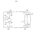
- FIG. 1 schematically shows a four-wheel drive vehicle 101.
- the four-wheel drive vehicle 101 has a front wheel power system that uses an engine as a driving source, and a rear wheel power system that uses an electric motor 4 as a driving source.
- the four-wheel drive vehicle 101 includes a motor torque transmission device 1, the engine 102, a transaxle 103, a pair of front wheels 104 and a pair of rear wheels 105.
- the motor torque transmission device 1 is arranged in the rear wheel power system of the four-wheel drive vehicle 101, and is supported by a vehicle body (not shown) of the four-wheel drive vehicle 101.
- the motor torque transmission device 1 is configured to transmit driving force based on the motor torque of the electric motor 4 to the rear wheels 105.
- the motor torque of the electric motor 4 is output to rear axle shafts 106 via a reduction-transmission mechanism 5 and a rear differential 3 (both will be described later in detail) to drive the rear wheels 105.
- the details of the motor torque transmission device 1, and the like, will be described later.
- the engine 102 is arranged in the front wheel power system of the four-wheel drive vehicle 101.
- the driving force of the engine 102 is output to front axle shafts 107 via the transaxle 103 to drive the front wheels 104.
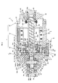
- FIG. 2 is an overall view of the motor torque transmission device.
- the motor torque transmission device 1 is formed mainly of a housing 2, the rear differential 3, the electric motor 4 and the reduction-transmission mechanism 5.
- the axis of the housing 2 is a rotation axis O that coincides with the axis of each rear axle shaft 106 (shown in FIG. 1 ).
- the rear differential 3 is a driving force transmission target (i.e., a member to which driving force is transmitted) that distributes driving force based on the motor torque to the rear wheels 105 (shown in FIG. 1 ).
- the electric motor 4 generates motor torque for driving the rear differential 3.
- the reduction-transmission mechanism 5 reduces the speed of rotation output from the electric motor 4 and transmits driving force to the rear differential 3.
- the housing 2 has a rotation force applying member 52 (described later in detail), a first housing element 20, a second housing element 21 and a third housing element 22.
- the housing 2 is arranged on the vehicle body.
- the first housing element 20 accommodates the rear differential 3.
- the second housing element 21 accommodates the electric motor 4.
- the third housing element 22 closes a first opening portion of the second housing element 21 (an opening portion on the opposite side of the second housing element 21 from a first housing element 20-side opening portion (second opening portion)).
- the first housing element 20 is arranged at a second side (left side in FIG. 2 ) of the housing 2.
- the entirety of the first housing element 20 is formed of a stepped closed-end cylindrical member that is open toward the second housing element 21.
- the bottom of the first housing element 20 has a shaft insertion hole 20a through which one of the rear axle shafts 106 (shown in FIG. 1 ) is passed.
- An annular protrusion 23 that protrudes toward the second housing element 21 is formed integrally on the open end face of the first housing element 20.
- the outer periphery of the protrusion 23 has an outside diameter smaller than the maximum outside diameter of the first housing element 20, and is formed of a cylindrical surface of which the central axis coincides with the rotation axis O.
- a seal member 24 is interposed between the inner periphery of the first housing element 20 and the outer periphery of the rear axle shaft 106. The seal member 24 seals the shaft insertion hole 20a.
- the second housing element 21 is arranged at the middle of the housing 2 in the axial direction.
- the entirety of the second housing element 21 is formed of an open-end cylindrical member that is open toward both sides in the direction of the rotation axis O.
- a stepped inward flange 21a which is interposed between the electric motor 4 and the reduction-transmission mechanism 5, is formed integrally with the second opening portion of the second housing element 21 (the opening portion on the first housing element 20-side).
- An annular member 25, to which a race is fitted, is fitted to the inner periphery of the inward flange 21a via an annular spacer 26.
- An annular protrusion 27, which protrudes toward the first housing element 20, is formed integrally on the second open end face of the second housing element 21 (the open end face on the first housing element 20-side).
- the outer periphery of the protrusion 27 has an outside diameter smaller than the maximum outside diameter of the second housing element 21.
- the protrusion 27 has substantially the same outside diameter as the outside diameter of the protrusion 23.
- the outer periphery of the protrusion 27 is formed of a cylindrical surface of which the central axis coincides with the rotation axis O.
- the third housing element 22 is arranged at the first side (right side in FIG. 2 ) of the housing 2.
- the entirety of the third housing element 22 is formed of a stepped closed-end cylindrical member that is open toward the second housing element 21.
- the bottom of the third housing element 22 has a shaft insertion hole 22a through which the other one of the rear axle shafts 106 is passed.
- a cylindrical portion 22b which protrudes toward the electric motor 4 and to which a stator is fitted, is formed integrally with the third housing element 22 so as to surround the inner opening of the shaft insertion hole 22a.
- a seal member 28 that seals the shaft insertion hole 22a is interposed between the inner periphery of the third housing element 22 and the outer periphery of the rear axle shaft 106.
- the rear differential 3 is formed of a bevel gear differential mechanism that includes a differential case 30, a pinion gear shaft 31, a pair of pinion gears 32 and a pair of side gears 33.
- the rear differential 3 is arranged at the second side of the motor torque transmission device 1.
- the torque of the differential case 30 is distributed from the pinion gear shaft 31 to the side gears 33 via the pinion gears 32, and further transmitted from the side gears 33 to the right and left rear wheels 105 (shown in FIG. 1 ) via the rear axle shafts 106 (shown in FIG. 1 ).
- the torque of the differential case 30 is differentially distributed to the right and left rear wheels 105 by the rotations of the pinion gears 32.
- the differential case 30 is arranged on the rotation axis O.
- the differential case 30 is rotatably supported by the first housing element 20 via a ball bearing 34, and is rotatably supported by a motor shaft (rotary shaft) 42 of the electric motor 4 via a ball bearing 35.
- the differential case 30 is configured to rotate about the rotation axis O upon reception of driving force based on the motor torque of the electric motor 4 from the reduction-transmission mechanism 5.
- the differential case 30 has an accommodation space 30a and a pair of shaft insertion holes 30b.
- a differential mechanism unit (the pinion gear shaft 31, the pinion gears 32 and the side gears 33) is accommodated in the accommodation space 30a.
- the shaft insertion holes 30b communicate with the accommodation space 30a, and the right and left rear axle shafts 106 are passed through the shaft insertion holes 30b.
- An annular flange 30c that faces the reduction-transmission mechanism 5 is formed integrally with the differential case 30.
- the flange 30c has a plurality of (six in the present embodiment) pin fitting holes 300c that are arranged at equal intervals around the rotation axis O.
- the pinion gear shaft 31 is arranged along an axis L perpendicular to the rotation axis O in the accommodation space 30a of the differential case 30. Rotation of the pinion gear shaft 31 about the axis L and movement of the pinion gear shaft 31 in the direction of the axis L are restricted by a pin 36.
- the pinion gears 32 are rotatably supported by the pinion gear shaft 31, and are accommodated in the accommodation space 30a of the differential case 30.
- the side gears 33 each have a shaft insertion hole 33a in which a corresponding one of the rear axle shafts 106 (shown in FIG. 1 ) is spline-coupled.
- the side gears 33 are accommodated in the accommodation space 30a of the differential case 30.
- the side gears 33 are configured such that the gear axes are perpendicular to the gear axes of the pinion gears 32 and the side gears 33 are in mesh with the pinion gears 32.
- the electric motor 4 includes a stator 40, a rotor 41 and the motor shaft 42, and is coupled, on the rotation axis O, to the rear differential 3 via the reduction-transmission mechanism 5.
- the stator 40 is connected to an electronic control unit (ECU) (not shown).
- ECU electronice control unit
- the electric motor 4 is configured such that the stator 40 receives a control signal from the ECU, motor torque for driving the rear differential 3 is generated with the use to the stator 40 and the rotor 41, and the rotor 41 is rotated together with the motor shaft 42.
- the stator 40 is arranged at the outer peripheral side of the electric motor 4, and is fitted to the inward flange 21a of the second housing element 21 with a fitting bolt 43.
- the rotor 41 is arranged at the inner peripheral side of the electric motor 4, and is fitted to the outer periphery of the motor shaft 42.
- the motor shaft 42 is arranged on the rotation axis O.
- the second end portion of the motor shaft 42 is rotatably supported by the inner periphery of the annular member 25 via a ball bearing 44 and a sleeve 45
- the first end portion of the motor shaft 42 is rotatably supported by the inner periphery of the third housing element 22 via a ball bearing 46.
- the entirety of the motor shaft 42 is formed of a cylindrical (hollow) shaft member through which the rear axle shafts 106 (shown in FIG. 1 ) is passed.
- An eccentric portion 42a and an eccentric portion 42b are formed integrally with the second end portion of the motor shaft 42.
- the central axis of the eccentric portion 42a is an axis O 1 that is offset from the axis of the motor shaft 42 (rotation axis O) by an eccentric amount ⁇ 1 .
- the eccentric portion 42a and the eccentric portion 42b are arranged so as to be next to each other along the rotation axis O and apart from each other in the circumferential direction around the rotation axis O at equal intervals (180°).
- the eccentric portion 42a and the eccentric portion 42b are arranged on the outer periphery of the motor shaft 42 such that the distance from the axis O 1 to the rotation axis O and the distance from the axis O 2 to the rotation axis O are equal to each other (the axes O 1 , O 2 are spaced apart at an equal interval from the rotation axis O in the radial direction) and the distance between the axis O 1 and the axis O 2 in one of the circumferential directions around the rotation axis O and the distance between the axis O 2 and the axis O 1 in the other circumferential direction around the rotation axis O are equal to each other.
- a resolver 47 is arranged at the first end portion of the motor shaft 42.
- the resolver 47 serves as a rotation angle detector, and is interposed between the outer periphery of the motor shaft 42 and the inner periphery of the cylindrical portion 22b.
- the resolver 47 has a stator 470 and a rotor 471, and is accommodated inside the third housing element 22.
- the stator 470 is fitted to the inner periphery of the cylindrical portion 22b.
- the rotor 471 is fitted to the outer periphery of the motor shaft 42.
- a spiral groove 42c is formed in the inner periphery of the motor shaft 42. Through the groove 42c, lubricating oil is supplied from the first opening portion on the resolver 47-side (right side in FIG. 2 ) to the second opening portion on the rear differential 3-side (left side in FIG. 2 ) as the motor shaft 42 rotates.
- FIG. 3 shows the reduction-transmission mechanism.
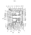
- FIG. 4 shows part of oil supply passages.
- the reduction-transmission mechanism 5 includes a speed reduction unit A, a lubricating oil supply unit B and a bearing unit C (bearing device).
- the reduction-transmission mechanism 5 is interposed between the rear differential 3 and the electric motor 4.
- the speed reduction unit A has a pair of input members 50, 51, the rotation force applying member 52 and output members 53.
- the speed reduction unit A is configured to reduce the speed of rotation output from the electric motor 4 and output driving force to the rear differential 3.
- the input member 50 (second input member) is formed of an external gear that has a center hole 50a of which the central axis coincides with the axis O 1 .
- the input member 50 is arranged so as to be closer to the rear differential 3 than the input member 51 (first input member).
- the input member 50 is rotatably supported by the motor shaft 42 via a ball bearing 54 (second rolling bearing).
- the ball bearing 54 is interposed between the inner periphery of the input member 50, which defines the center hole 50a, and the eccentric portion 42a.
- the input member 50 is configured to make circular motion (revolving motion about the rotation axis O) in the directions of the arrows m 1 , m 2 with the eccentric amount ⁇ , upon reception of motor torque from the electric motor 4.
- the input member 50 has a plurality of (six in the present embodiment) pin insertion holes (through-holes) 50b that are arranged at equal intervals around the axis O 1 .
- the hole diameter of each pin insertion hole 50b is set to a value that is larger than a value obtained by adding the outside diameter of a needle roller bearing 55 to the outside diameter of each output member 53.
- External teeth 50c having an involute tooth profile, are formed on the outer periphery of the input member 50 at a portion of which the central axis coincides with the axis O 1 .
- the outside diameter of each needle roller bearing 55 is set to a value that is smaller than the outside diameter of the ball bearing 54.
- the input member 51 is formed of an external gear that has a center hole 51a of which the central axis coincides with the axis O 2 .
- the input member 51 is arranged so as to be closer to the electric motor 4 than the input member 50.
- the input member 51 is rotatably supported by the motor shaft 42 via a ball bearing 56 (first rolling bearing).
- the ball bearing 56 is interposed between the inner periphery of the input member 51, which defines the center hole 51a, and the eccentric portion 42b.
- the input member 51 is configured to make circular motion (revolving motion about the rotation axis O) in the directions of the arrows m 1 , m 2 with the eccentric amount ⁇ , upon reception of motor torque from the electric motor 4.
- the input member 51 has a plurality of (six in the present embodiment) pin insertion holes (through-holes) 51b that are arranged at equal intervals around the axis O 2 .
- the hole diameter of each pin insertion hole 51b is set to a value that is larger than a value obtained by adding the outside diameter of a needle roller bearing 57 to the outside diameter of each output member 53.
- External teeth 51c having an involute tooth profile, are formed on the outer periphery of the input member 51 at a portion of which the central axis coincides with the axis O 2 .
- the outside diameter of each needle roller bearing 57 is set to a value that is smaller than the outside diameter of the ball bearing 56.
- the rotation force applying member 52 is formed of an internal gear of which the central axis coincides with the rotation axis O.
- the rotation force applying member 52 is interposed between the first housing element 20 and the second housing element 21.
- the entirety of the rotation force applying member 52 is formed of an open-end cylindrical member that constitutes part of the housing 2 and that is open toward both sides in the direction of the rotation axis O.
- the rotation force applying member 52 is in mesh with the input members 50, 51.
- the rotation force applying member 52 is configured to apply rotation force in the direction of the arrow n 1 to the input member 50 that makes revolving motion upon reception of motor torque from the electric motor 4, and to apply rotation force in the direction of the arrow l 1 to the input member 51 that makes revolving motion upon reception of motor torque from the electric motor 4.
- the inner periphery of the rotation force applying member 52 has a first fitting portion 52a and a second fitting portion 52b that are located at a predetermined distance in the direction of the rotation axis O.
- the first fitting portion 52a is fitted to the outer periphery of the protrusion 23.
- the second fitting portion 52b is fitted to the outer periphery of the protrusion 27.
- the inner periphery of the rotation force applying member 52 has internal teeth 52c having an involute tooth profile.
- the internal teeth 52c are located between the first fitting portion 52a and the second fitting portion 52b.
- the external teeth 50c of the input member 50 and the external teeth 51c of the input member 51 are in mesh with the internal teeth 52c.
- the number Z 3 of the internal teeth 52c is set to 208, for example.
- the output members 53 are a plurality of (six in the present embodiment) bolts each having a threaded portion 53a at one end and a head 53b at the other end.
- the threaded portions 53a of the output members 53 are passed through the pin insertion holes 50b of the input member 50 and the pin insertion holes 51b of the input member 51 and then fitted in the pin fitting holes 300c of the differential case 30.
- the output members 53 are arranged so as to be passed through an annular spacer 58 that is interposed between each head 53b and the input member 51.
- the output members 53 are configured to receive rotation force, applied by the rotation force applying member 52, from the input members 50, 51 and output the rotation force to the differential case 30 as the torque of the differential case 30.
- the needle roller bearing 55 and the needle roller bearing 57 are fitted to the outer periphery of each output member 53 at a portion between the threaded portion 53a and the head 53b.
- the needle roller bearing 55 reduces contact resistance between each output member 53 and the inner periphery, which defines the corresponding pin insertion hole 50b of the input member 50.
- the needle roller bearing 57 reduces contact resistance between each output member 53 and the inner periphery, which defines the corresponding pin insertion hole 51b of the input member 51.
- the needle roller bearings 55 each have a race 550 and needle rollers 551.
- the race 550 is able to contact the inner periphery, which defines a corresponding one of the pin insertion holes 50b of the input member 50.
- the needle rollers 551 roll between the race 550 and the outer periphery of a corresponding one of the output members 53.
- the needle roller bearings 57 each have a race 570 and needle rollers 571.
- the race 570 is able to contact the inner periphery, which defines a corresponding one of the pin insertion holes 51b of the input member 51.
- the needle rollers 571 roll between the race 570 and the outer periphery of a corresponding one of the output members 53.
- the lubricating oil supply unit B includes an oil tank (not shown), oil delivery passages 61, 62, an oil introduction passage 63 and an oil supply passage 64.
- the lubricating oil supply unit B is configured such that the lubricating oil is supplied to the ball bearings 54, 56, and the like, through the oil supply passage 64 by centrifugal force generated in accordance with the rotation of the motor shaft 42.
- the oil delivery passages 61, 62 are open toward the inside and outside of the housing 2, and communicate with the oil tank via tube members (not shown).
- the oil delivery passages 61, 62 are formed in the first housing element 20 at equal intervals around the rotation axis O.
- the oil delivery passages 61, 62 are configured such that, through the delivery passages 61, 62, the lubricating oil inside the housing 2 is delivered to the outside of the housing 2 and the lubricating oil is caused to flow toward the oil tank with the use of, for example, a pump.
- the oil introduction passage 63 functions as an oil passage that extends from the oil tank to the oil supply passage 64, and is formed in the third housing element 22 with a portion thereof exposed on the outside of the housing 2.
- the oil introduction passage 63 is configured such that the lubricating oil in the oil tank flows through the oil introduction passage 63 to be introduced into the oil supply passage 64.
- the oil supply passage 64 has a first oil supply passage 640, a second oil supply passage 641 and a third oil supply passage 642.
- the oil supply passage 64 is formed in the motor shaft 42 and the input member 50.
- the first oil supply passage 640 communicates with the groove 42c of the motor shaft 42, and functions as an oil passage that extends from the oil introduction passage 63 to the third oil supply passage 642.
- the first oil supply passage 640 is formed in the motor shaft 42.
- the second oil supply passage 641 has, for example, an oil flow passage 641a (first oil flow passage) and an oil flow passage 641b (second oil flow passage).
- the oil flow passage 641a is formed in the eccentric portion 42b.
- the oil flow passage 641b is formed in the input member 50.
- the second oil supply passage 641 is configured such that the lubricating oil is supplied from the ball bearing 54-side to the ball bearing 56 by centrifugal force generated in accordance with the rotation of the motor shaft 42.
- the oil flow passage 641a is formed in the eccentric portion 42b, and is open between an inner ring 540 and an outer ring 541 of the ball bearing 54.
- the oil flow passage 641b is formed in the input member 50, and is open between an inner ring 560 and an outer ring 561 of the ball bearing 56.
- the third oil supply passage 642 functions as an oil passage that extends from the first oil supply passage 640 to a space G between the ball bearing 54 and the ball bearing 35.
- the third oil supply passage 642 is formed in the motor shaft 42 so as to open at the inner periphery and outer periphery of the motor shaft 42.
- the third oil supply passage 642 is configured to supply lubricating oil from the first oil supply passage 640 to the space G by centrifugal force generated in accordance with the rotation of the motor shaft 42.
- the bearing unit C includes the ball bearings 54, 56, and is arranged on the outer periphery of the motor shaft 42.
- the bearing unit C is configured such that the ball bearing 54 is interposed between the inner periphery of the input member 50, which defines the center hole 50a, and the outer periphery of the eccentric portion 42a to support the input member 50 such that the input member 50 is rotatable relative to the motor shaft 42.
- the bearing unit C is configured such that the ball bearing 56 is interposed between the inner periphery of the input member 51, which defines the center hole 51a, and the outer periphery of the eccentric portion 42b to support the input member 51 such that the input member 51 is rotatable relative to the motor shaft 42.
- the ball bearing 54 includes the inner ring 540, the outer ring 541, a plurality of rolling elements 542 and a cage 543.
- the ball bearing 54 is formed of, for example, a deep groove ball bearing.
- the rolling elements 542 roll between a first raceway (inner raceway) of the inner ring 540 and a second raceway (outer raceway) of the outer ring 541.
- the rolling elements 542 are rollably retained by the cage 543 at equal intervals around the central axis O 1 (shown in FIG. 2 ).
- the cage 543 has an annular base portion 543a and a plurality of partition wall portions 543b.
- the base portion 543a is interposed between the inner ring 540 and the outer ring 541.
- the partition wall portions 543b are used to form pockets together with the base portion 543a.
- Part of the base portion 543a protrudes axially outward (outward of the inner ring 540 and the outer ring 541) from the end face (inner raceway) of the inner ring 540, and forms an oil receiving portion that receives the lubricating oil from the third oil supply passage 642.
- the base portion 543a is arranged at the second side (left side in FIG. 4 ) of the cage 543.
- the partition wall portions 543b are arranged at the first side (right side in FIG. 4 ) of the cage 543 at equal intervals in the circumferential direction of the base portion 543a.
- the dimensions of the cage 543 are set such that the inner diameter gradually increases from a second axial end portion toward a first axial end portion except for the pockets.
- the cage 543 may be, for example, a snap cage.
- the ball bearing 56 includes the inner ring 560, the outer ring 561, a plurality of rolling elements 562 and a cage 563.
- the ball bearing 56 is formed of, for example, a deep groove ball bearing.
- the rolling elements 562 roll between a first raceway (inner raceway) of the inner ring 560 and a second raceway (outer raceway) of the outer ring 561.
- the rolling elements 562 are rollably retained by the cage 563 at equal intervals around the central axis O 1 (shown in FIG. 2 ).
- the cage 563 has an annular base portion 563a and a plurality of partition wall portions 563b.
- the base portion 563a is interposed between the inner ring 560 and the outer ring 561.
- the partition wall portions 563b are used to form pockets together with the base portion 563a.
- Part of the base portion 563a protrudes axially outward (outward of the inner ring 560 and the outer ring 561) from the end face (inner raceway) of the inner ring 560, and forms an oil receiving portion that receives the lubricating oil from the ball bearing 54-side, at a portion around the rotation axis O (shown in the drawing) and axially outward of the ball bearing 56.
- the base portion 563a is arranged at the second side (left side in FIG. 4 ) of the cage 563.
- the partition wall portions 563b are arranged at the first side (right side in FIG. 4 ) of the cage 563 at equal intervals in the circumferential direction of the base portion 563a.
- the dimensions of the cage 563 are set such that the inner diameter gradually increases from a second axial end portion toward a first axial end portion except for the pockets.
- the cage 563 may be, for example, a snap cage.
- the input members 50, 51 each make circular motion with the eccentric amount ⁇ , for example, in the direction of the arrow m 1 shown in FIG. 3 .
- the input member 50 rotates about the axis O 1 (in the direction of the arrow n 1 shown in FIG. 3 ) while the external teeth 50c are meshed with the internal teeth 52c of the rotation force applying member 52
- the input member 51 rotates about the axis O 2 (in the direction of the arrow l 1 shown in FIG. 3 ) while the external teeth 51c are meshed with the internal teeth 52c of the rotation force applying member 52.
- the rear differential 3 is driven, and driving force based on the motor torque of the electric motor 4 is distributed to the rear axle shafts 106 shown in FIG. 1 and transmitted to the right and left rear wheels 105.
- the lubricating oil introduced from the oil introduction passage 63 to the first oil supply passage 640 flows through the first oil supply passage 640, the lubricating oil flows through the third oil supply passage 642 as shown in FIG. 4 , and is supplied to the space G between the ball bearing 54 and the ball bearing 35.
- the lubricating oil supplied to the space G is received by the base portion 543a of the cage 543.
- the lubricating oil flows from the base portion 543a of the cage 543 to a space between the inner ring 540 and the outer ring 541, flows between the inner ring 540 and the outer ring 541, and is discharged from the ball bearing 54.
- the lubricating oil discharged from the ball bearing 54 flows into the second oil supply passage 641 (oil flow passages 641a, 641b), flows through the oil flow passages 641a, 641b, and is supplied to the ball bearing 56.
- the base portion 563a of the cage 563 receives the lubricating oil.
- the lubricating oil flows from the base portion 563a of the cage 563 to a space between the inner ring 560 and the outer ring 561, flows between the inner ring 560 and the outer ring 561, and is discharged from the ball bearing 56.
- the lubricating oil is supplied to the ball bearings 54, 56 by the lubricating oil supply unit B to lubricate the ball bearings 54, 56.
- the motor torque transmission device 1 may be driven as in the case of the above-described embodiment even when the input members 50, 51 are caused to make circular motions in the direction of the arrow m2.
- the rotation motion of the input member 50 is made in the direction of the arrow n 2
- the rotation motion of the input member 51 is made in the direction of the arrow l 2 .
- the bearing device, the speed reduction mechanism including the bearing device, and the motor torque transmission device according to the invention are described on the basis of the above-described embodiment.
- the invention is not limited to the above-described embodiment.
- the invention may be implemented in various other embodiments without departing from the scope of the invention, and, for example, the invention may be implemented in the following alternative embodiments.
- the two ball bearings 54, 56 are used to support the input members 50, 51 such that the input members 50, 51 are rotatable relative to the motor shaft 42 (eccentric portions 42a, 42b); however, the invention is not limited to this configuration.
- the number of bearings is determined on the basis of the number of the input members.
- the ball bearing 54 includes the cage 543 formed of a snap cage
- the ball bearing 56 includes the cage 563 formed of a snap cage
- the ball bearings 54, 56 are formed of deep groove ball bearings.
- the invention is not limited to this configuration.
- ball bearings 65, 66 formed of angular contact ball bearings may be used.
- the ball bearing 65 includes an inner ring 650, an outer ring 651, a plurality of rolling elements 652 and a cage 653.
- the cage 653 is formed of a window-type cage, and the rolling elements 652 are rollably retained by the cage 653 at equal intervals in the circumferential direction.
- the rolling elements 652 roll between a first raceway (inner raceway) of the inner ring 650 and a first raceway (inner raceway) of the outer ring 651.
- the cage 653 is formed of a window-type cage that retains the rolling elements 652 at equal intervals in the circumferential direction such that the rolling elements 652 are rollable.
- the dimensions of the cage 653 are set such that a second axial end portion protrudes axially outward from the end face (inner raceway) of the inner ring 650 and the inner diameter gradually increases from the second axial end portion toward a first axial end portion except for the pockets.
- the ball bearing 66 includes an inner ring 660, an outer ring 661, a plurality of rolling elements 662 and a cage 663.
- the cage 662 is formed of a window-type cage, and the rolling elements 662 are rollably retained by the cage 663 at equal intervals in the circumferential direction.
- the rolling elements 662 roll between the first raceway (inner raceway) of the inner ring 660 and the first raceway (outer raceway) of the outer ring 661.
- the cage 663 is formed of a window-type cage, and the rolling elements 662 are rollably retained by the cage 663 at equal intervals in the circumferential direction.
- the dimensions of the cage 663 are set such that a second axial end portion protrudes axially outward from the end face (inner raceway) of the inner ring 660 and the inner diameter gradually increases from the second axial end portion toward a first axial end portion except for the pockets.
- the cylindrical roller bearing 67 includes an inner ring 670, an outer ring 671, a plurality of rolling elements 672 and a cage 673.
- the cage 673 is formed of a window-type cage, and the rolling elements 672 are rollably retained by the cage 673 at equal intervals in the circumferential direction.
- the rolling elements 672 roll between a first raceway (inner raceway) of the inner ring 670 and a second raceway (outer raceway) of the outer ring 671.
- the cage 673 is formed of a window-type cage, and the rolling elements 672 are rollably retained by the cage 673 at equal intervals in the circumferential direction.
- the dimensions of the cage 673 are set such that a second axial end portion protrudes axially outward from the end face (inner raceway) of the inner ring 670 and the inner diameter gradually increases from the second axial end portion toward a first axial end portion except for the pockets.
- the cylindrical roller bearing 68 includes an inner ring 680, an outer ring 681, a plurality of rolling elements 682 and a cage 683.
- the rolling elements 682 roll between a first raceway (inner raceway) of the inner ring 680 and a second raceway (outer raceway) of the outer ring 681.
- the cage 683 is formed of a window-type cage, and the rolling elements 682 are rollably retained by the cage 683 at equal intervals in the circumferential direction.
- the dimensions of the cage 683 are set such that a second axial end portion protrudes axially outward from the end face (inner raceway) of the inner ring 680 and the inner diameter gradually increases from the second axial end portion toward a first axial end portion except for the pockets.
- the eccentric portion 42a and the eccentric portion 42b are arranged on the outer periphery of the motor shaft 42 such that the distance from the axis O 1 of the center hole 50a to the rotation axis O and the distance from the axis O 2 of the center hole 51a to the rotation axis O are equal to each other and the distance between the axis O 1 of the center hole 50a and the axis O 2 of the center hole 51a in one of the circumferential directions around the rotation axis O and the distance between the axis O 2 of the center hole 51a and the axis O 1 of the center hole 50a in the other circumferential direction around the rotation axis O are equal to each other.
- the motor shaft 42 of the electric motor 4 is provided with the input members 50, 51 at portions that are apart from each other in the circumferential direction around the axis of the motor shaft 42 (rotation axis O) at equal intervals (180°).
- the input members 50, 51 are arranged so as to correspond to the eccentric portions 42a, 42b, respectively.
- the invention is not limited to this configuration, and the number of the input members may be changed as needed.
- the axis of the first eccentric portion, the axis of the second eccentric portion, ..., and the axis of the nth eccentric portion are successively arranged in one direction about the axis of the motor shaft on an imaginary plane that is perpendicular to the axis of the electric motor (motor shaft).
- the eccentric portions are arranged around the motor shaft such that the distance from the axis of each eccentric portion to the axis of the motor shaft is equal to one another and an angle formed between line segments that connect the axis of the motor shaft to the respective axes of any adjacent two eccentric portions among the first eccentric portion, the second eccentric portion, ..., and the nth eccentric portion is set to 360°/n.
- the n input members are arranged on the motor shaft at portions that are spaced at intervals of 360°/n about the axis of the motor shaft so as to correspond to the respective eccentric portions.
- the axis of the first eccentric portion, the axis of the second eccentric portion and the axis of the third eccentric portion are successively arranged in one direction around the axis of the motor shaft on an imaginary plane that is perpendicular to the axis of the motor shaft.
- the eccentric portions are arranged around the motor shaft such that the distance from the axis of each eccentric portion to the axis of the motor shaft is equal to one another and an angle formed between line segments that connect the axis of the motor shaft to the respective axes of any adjacent two eccentric portions among the first eccentric portion, the second eccentric portion and the third eccentric portion is set to 120°.
- the three input members are arranged on the motor shaft at portions that are spaced at intervals of 120° about the axis of the motor shaft so as to correspond to the first eccentric portion, the second eccentric portion and the third eccentric portion.
- the invention is not limited to this configuration.
- the invention may also be applied to an electric vehicle, which is a four-wheel drive vehicle or a two-wheel drive vehicle, using only an electric motor as a driving source.
- the invention may also be applied to a four-wheel drive vehicle that has a first drive shaft driven by an engine and an electric motor and a second drive shaft driven by an electric motor, as in the case of the above-described embodiment.
- the invention is not limited to this configuration.
- a roller bearing other than a needle roller bearing or a ball bearing may be used instead of the needle roller bearing.
- a ball bearing or a roller bearing may be, for example, a deep groove ball bearing, an angular contact ball bearing, a long cylindrical roller bearing, a cylindrical roller bearing, a tapered roller bearing, a spherical roller bearing, or the like.
- a plain bearing may be used instead of a rolling bearing.
- a cage of each of ball bearings arranged on respective outer peripheries of eccentric portions of a motor shaft has an annular base portion interposed between an inner ring and an outer ring and a plurality of partition wall portions for forming pockets together with the base portion.
- part of the base portion protrudes axially outward from the inner raceway and forms an oil receiving portion that receives lubricating oil from the second rolling bearing side, at a portion around the rotation axis and axially outward of the first rolling bearing.
Landscapes
- Engineering & Computer Science (AREA)
- General Engineering & Computer Science (AREA)
- Mechanical Engineering (AREA)
- Transportation (AREA)
- Chemical & Material Sciences (AREA)
- Combustion & Propulsion (AREA)
- Power Engineering (AREA)
- Sustainable Development (AREA)
- Sustainable Energy (AREA)
- Life Sciences & Earth Sciences (AREA)
- Rolling Contact Bearings (AREA)
- Retarders (AREA)
- General Details Of Gearings (AREA)
Abstract
Description
- The invention relates to a bearing device that is suitably used in, for example, an electric vehicle that has an electric motor serving as a driving source, a speed reduction mechanism that includes the bearing device, and a motor torque transmission device.
- There is a conventional motor torque transmission device that is mounted in an automobile, and that includes an electric motor and a reduction-transmission mechanism (for example, see Japanese Patent Application Publication No.
2007-218407 JP 2007-218407 A - The electric motor has a motor shaft that is rotated by electric power from an in-vehicle battery. The motor shaft is arranged along the axis of the reduction-transmission mechanism. Eccentric portions are integrally formed on the outer periphery of the motor shaft. The central axis of each eccentric portion is an axis that is offset from the axis of the motor shaft by a predetermined eccentric amount.
- The reduction-transmission mechanism has a pair of reduction-transmission units provided around the axis of the reduction-transmission mechanism, and a housing that accommodates the reduction-transmission units. The reduction-transmission mechanism is interposed between the electric motor and the differential mechanism, and is coupled to the motor shaft and the differential mechanism (differential case). One of the reduction-transmission units is coupled to the motor shaft, and the other one of the reduction-transmission units is coupled to the differential case.
- With the above configuration, the motor shaft of the electric motor is rotated by electric power from the in-vehicle battery, and accordingly the motor torque is transmitted from the electric motor to the differential mechanism via the reduction-transmission mechanism and then distributed to right and left wheels by the differential mechanism.
- The reduction-transmission units of the motor torque transmission device of this type have a pair of disc-shaped revolving members, a plurality of outer pins and a plurality of inner pins. The revolving members make revolving motions in accordance with the rotation of the motor shaft of the electric motor. The outer pins apply rotation force to the revolving members. The inner pins are arranged radially inward of the outer pins, and output the rotation force of the revolving members to the differential mechanism as driving force (torque).
- The revolving members each have a center hole and a plurality of pin insertion holes. The revolving members are rotatably supported by the eccentric portions of the motor shaft via bearings (cam-side bearings). The central axis of each center hole coincides with the axis of a corresponding one of the eccentric portions of the motor shaft. The pin insertion holes are arranged at equal intervals around the central axis of each center hole.
- The outer pins are arranged at equal intervals around the axis of the motor shaft, and are fitted to the housing of the reduction-transmission mechanism.
- The inner pins are passed through the pin insertion holes of the revolving members. The inner pins are arranged at equal intervals on a circle around the axis of the rotation member at wheel side, and are fitted to the differential case. Bearings (pin-side bearings) are fitted to the inner pins. The bearings are used to reduce contact resistance between the inner pins and the inner peripheries which define the pin insertion holes of the revolving members.
- However, in the motor torque transmission device described in
JP 2007-218407 A - It is an object of the invention to provide a bearing device in which an amount of lubricating oil on the inner side in the radial direction perpendicular to the rotation axis is increased to sufficiently supply the lubricating oil to a bearing near the rotation axis, a speed reduction mechanism including the bearing device, and a motor torque transmission device.
- An aspect of the invention relates to a bearing device, including: a rotary shaft that has at least two eccentric portions that are arranged at equal intervals around a rotation axis of the rotary shaft, and that have respective central axes that are spaced apart at equal interval from the rotation axis in a radial direction of the rotary shaft; and at least two rolling bearings that include a first rolling bearing and a second rolling bearing, that are respectively arranged on outer peripheries of the at least two eccentric portions of the rotary shaft, and each of which includes a plurality of rolling elements that roll between an inner raceway and an outer raceway and a cage by which the rolling elements are rollably retained at equal intervals around the corresponding central axis. The cage of each of the at least two rolling bearings has an annular base portion that is interposed between the inner raceway and the outer raceway and a plurality of partition wall portions for forming pockets together with the base portion. In the first rolling bearing, part of the base portion protrudes axially outward from the inner raceway and forms an oil receiving portion that receives lubricating oil from the second rolling bearing side, at a portion around the rotation axis and axially outward of the first rolling bearing.
- Features, advantages, and technical and industrial significance of exemplary embodiments of the invention will be described below with reference to the accompanying drawings, in which like numerals denote like elements, and wherein:
-
FIG. 1 is a plan view schematically illustrating a vehicle in which a motor torque transmission device according to an embodiment of the invention is mounted; -
FIG. 2 is a sectional view illustrating the motor torque transmission device according to the embodiment of the invention; -
FIG. 3 is a sectional view schematically illustrating main portions of a reduction-transmission mechanism of the motor torque transmission device according to the embodiment of the invention; -
FIG. 4 is a sectional view illustrating a bearing unit of the motor torque transmission device according to the embodiment of the invention; -
FIG. 5 is a sectional view illustrating a bearing unit of the motor torque transmission device according to a first modified example of the embodiment of the invention; and -
FIG. 6 is a sectional view illustrating a bearing unit of the motor torque transmission device according to a second modified example of the embodiment of the invention. - Hereinafter, a motor torque transmission device according to an embodiment of the invention will be described in detail with reference to the accompanying drawings.
-
FIG. 1 schematically shows a four-wheel drive vehicle 101. As shown inFIG. 1 , the four-wheel drive vehicle 101 has a front wheel power system that uses an engine as a driving source, and a rear wheel power system that uses an electric motor 4 as a driving source. The four-wheel drive vehicle 101 includes a motortorque transmission device 1, theengine 102, atransaxle 103, a pair offront wheels 104 and a pair ofrear wheels 105. - The motor
torque transmission device 1 is arranged in the rear wheel power system of the four-wheel drive vehicle 101, and is supported by a vehicle body (not shown) of the four-wheel drive vehicle 101. - The motor
torque transmission device 1 is configured to transmit driving force based on the motor torque of the electric motor 4 to therear wheels 105. Thus, the motor torque of the electric motor 4 is output torear axle shafts 106 via a reduction-transmission mechanism 5 and a rear differential 3 (both will be described later in detail) to drive therear wheels 105. The details of the motortorque transmission device 1, and the like, will be described later. - The
engine 102 is arranged in the front wheel power system of the four-wheel drive vehicle 101. Thus, the driving force of theengine 102 is output tofront axle shafts 107 via thetransaxle 103 to drive thefront wheels 104. -
FIG. 2 is an overall view of the motor torque transmission device. As shown inFIG. 2 , the motortorque transmission device 1 is formed mainly of ahousing 2, the rear differential 3, the electric motor 4 and the reduction-transmission mechanism 5. The axis of thehousing 2 is a rotation axis O that coincides with the axis of each rear axle shaft 106 (shown inFIG. 1 ). The rear differential 3 is a driving force transmission target (i.e., a member to which driving force is transmitted) that distributes driving force based on the motor torque to the rear wheels 105 (shown inFIG. 1 ). The electric motor 4 generates motor torque for driving the rear differential 3. The reduction-transmission mechanism 5 reduces the speed of rotation output from the electric motor 4 and transmits driving force to the rear differential 3. - The
housing 2 has a rotation force applying member 52 (described later in detail), afirst housing element 20, asecond housing element 21 and athird housing element 22. Thehousing 2 is arranged on the vehicle body. Thefirst housing element 20 accommodates the rear differential 3. Thesecond housing element 21 accommodates the electric motor 4. Thethird housing element 22 closes a first opening portion of the second housing element 21 (an opening portion on the opposite side of thesecond housing element 21 from a first housing element 20-side opening portion (second opening portion)). - The
first housing element 20 is arranged at a second side (left side inFIG. 2 ) of thehousing 2. The entirety of thefirst housing element 20 is formed of a stepped closed-end cylindrical member that is open toward thesecond housing element 21. The bottom of thefirst housing element 20 has ashaft insertion hole 20a through which one of the rear axle shafts 106 (shown inFIG. 1 ) is passed. Anannular protrusion 23 that protrudes toward thesecond housing element 21 is formed integrally on the open end face of thefirst housing element 20. The outer periphery of theprotrusion 23 has an outside diameter smaller than the maximum outside diameter of thefirst housing element 20, and is formed of a cylindrical surface of which the central axis coincides with the rotation axis O. Aseal member 24 is interposed between the inner periphery of thefirst housing element 20 and the outer periphery of therear axle shaft 106. Theseal member 24 seals theshaft insertion hole 20a. - The
second housing element 21 is arranged at the middle of thehousing 2 in the axial direction. The entirety of thesecond housing element 21 is formed of an open-end cylindrical member that is open toward both sides in the direction of the rotation axis O. A steppedinward flange 21a, which is interposed between the electric motor 4 and the reduction-transmission mechanism 5, is formed integrally with the second opening portion of the second housing element 21 (the opening portion on the first housing element 20-side). Anannular member 25, to which a race is fitted, is fitted to the inner periphery of theinward flange 21a via anannular spacer 26. Anannular protrusion 27, which protrudes toward thefirst housing element 20, is formed integrally on the second open end face of the second housing element 21 (the open end face on the first housing element 20-side). The outer periphery of theprotrusion 27 has an outside diameter smaller than the maximum outside diameter of thesecond housing element 21. Theprotrusion 27 has substantially the same outside diameter as the outside diameter of theprotrusion 23. The outer periphery of theprotrusion 27 is formed of a cylindrical surface of which the central axis coincides with the rotation axis O. - The
third housing element 22 is arranged at the first side (right side inFIG. 2 ) of thehousing 2. The entirety of thethird housing element 22 is formed of a stepped closed-end cylindrical member that is open toward thesecond housing element 21. The bottom of thethird housing element 22 has ashaft insertion hole 22a through which the other one of therear axle shafts 106 is passed. Acylindrical portion 22b, which protrudes toward the electric motor 4 and to which a stator is fitted, is formed integrally with thethird housing element 22 so as to surround the inner opening of theshaft insertion hole 22a. Aseal member 28 that seals theshaft insertion hole 22a is interposed between the inner periphery of thethird housing element 22 and the outer periphery of therear axle shaft 106. - The rear differential 3 is formed of a bevel gear differential mechanism that includes a
differential case 30, apinion gear shaft 31, a pair of pinion gears 32 and a pair of side gears 33. The rear differential 3 is arranged at the second side of the motortorque transmission device 1. - Thus, the torque of the
differential case 30 is distributed from thepinion gear shaft 31 to the side gears 33 via the pinion gears 32, and further transmitted from the side gears 33 to the right and left rear wheels 105 (shown inFIG. 1 ) via the rear axle shafts 106 (shown inFIG. 1 ). - When there arises a difference in driving resistance between the right and left
rear wheels 105, the torque of thedifferential case 30 is differentially distributed to the right and leftrear wheels 105 by the rotations of the pinion gears 32. - The
differential case 30 is arranged on the rotation axis O. Thedifferential case 30 is rotatably supported by thefirst housing element 20 via aball bearing 34, and is rotatably supported by a motor shaft (rotary shaft) 42 of the electric motor 4 via aball bearing 35. Thedifferential case 30 is configured to rotate about the rotation axis O upon reception of driving force based on the motor torque of the electric motor 4 from the reduction-transmission mechanism 5. - The
differential case 30 has anaccommodation space 30a and a pair ofshaft insertion holes 30b. A differential mechanism unit (thepinion gear shaft 31, the pinion gears 32 and the side gears 33) is accommodated in theaccommodation space 30a. The shaft insertion holes 30b communicate with theaccommodation space 30a, and the right and leftrear axle shafts 106 are passed through theshaft insertion holes 30b. - An
annular flange 30c that faces the reduction-transmission mechanism 5 is formed integrally with thedifferential case 30. Theflange 30c has a plurality of (six in the present embodiment) pin fitting holes 300c that are arranged at equal intervals around the rotation axis O. - The
pinion gear shaft 31 is arranged along an axis L perpendicular to the rotation axis O in theaccommodation space 30a of thedifferential case 30. Rotation of thepinion gear shaft 31 about the axis L and movement of thepinion gear shaft 31 in the direction of the axis L are restricted by apin 36. - The pinion gears 32 are rotatably supported by the
pinion gear shaft 31, and are accommodated in theaccommodation space 30a of thedifferential case 30. - The side gears 33 each have a
shaft insertion hole 33a in which a corresponding one of the rear axle shafts 106 (shown inFIG. 1 ) is spline-coupled. The side gears 33 are accommodated in theaccommodation space 30a of thedifferential case 30. The side gears 33 are configured such that the gear axes are perpendicular to the gear axes of the pinion gears 32 and the side gears 33 are in mesh with the pinion gears 32. - The electric motor 4 includes a
stator 40, arotor 41 and themotor shaft 42, and is coupled, on the rotation axis O, to the rear differential 3 via the reduction-transmission mechanism 5. Thestator 40 is connected to an electronic control unit (ECU) (not shown). The electric motor 4 is configured such that thestator 40 receives a control signal from the ECU, motor torque for driving the rear differential 3 is generated with the use to thestator 40 and therotor 41, and therotor 41 is rotated together with themotor shaft 42. - The
stator 40 is arranged at the outer peripheral side of the electric motor 4, and is fitted to theinward flange 21a of thesecond housing element 21 with afitting bolt 43. - The
rotor 41 is arranged at the inner peripheral side of the electric motor 4, and is fitted to the outer periphery of themotor shaft 42. - The
motor shaft 42 is arranged on the rotation axis O. In addition, the second end portion of themotor shaft 42 is rotatably supported by the inner periphery of theannular member 25 via aball bearing 44 and asleeve 45, and the first end portion of themotor shaft 42 is rotatably supported by the inner periphery of thethird housing element 22 via aball bearing 46. The entirety of themotor shaft 42 is formed of a cylindrical (hollow) shaft member through which the rear axle shafts 106 (shown inFIG. 1 ) is passed. - An
eccentric portion 42a and aneccentric portion 42b, both of which are circular in planar view, are formed integrally with the second end portion of themotor shaft 42. The central axis of theeccentric portion 42a is an axis O1 that is offset from the axis of the motor shaft 42 (rotation axis O) by an eccentric amount δ1. The central axis of theeccentric portion 42b is an axis O2 that is offset from the rotation axis O by an eccentric amount δ2 (δ1 = δ2 = δ). Theeccentric portion 42a and theeccentric portion 42b are arranged so as to be next to each other along the rotation axis O and apart from each other in the circumferential direction around the rotation axis O at equal intervals (180°). That is, theeccentric portion 42a and theeccentric portion 42b are arranged on the outer periphery of themotor shaft 42 such that the distance from the axis O1 to the rotation axis O and the distance from the axis O2 to the rotation axis O are equal to each other (the axes O1, O2 are spaced apart at an equal interval from the rotation axis O in the radial direction) and the distance between the axis O1 and the axis O2 in one of the circumferential directions around the rotation axis O and the distance between the axis O2 and the axis O1 in the other circumferential direction around the rotation axis O are equal to each other. - A resolver 47 is arranged at the first end portion of the
motor shaft 42. The resolver 47 serves as a rotation angle detector, and is interposed between the outer periphery of themotor shaft 42 and the inner periphery of thecylindrical portion 22b. The resolver 47 has astator 470 and arotor 471, and is accommodated inside thethird housing element 22. Thestator 470 is fitted to the inner periphery of thecylindrical portion 22b. Therotor 471 is fitted to the outer periphery of themotor shaft 42. - A
spiral groove 42c is formed in the inner periphery of themotor shaft 42. Through thegroove 42c, lubricating oil is supplied from the first opening portion on the resolver 47-side (right side inFIG. 2 ) to the second opening portion on the rear differential 3-side (left side inFIG. 2 ) as themotor shaft 42 rotates. -
FIG. 3 shows the reduction-transmission mechanism.FIG. 4 shows part of oil supply passages. As shown inFIG. 2 andFIG. 3 , the reduction-transmission mechanism 5 includes a speed reduction unit A, a lubricating oil supply unit B and a bearing unit C (bearing device). The reduction-transmission mechanism 5 is interposed between the rear differential 3 and the electric motor 4. - The speed reduction unit A has a pair of
input members force applying member 52 andoutput members 53. The speed reduction unit A is configured to reduce the speed of rotation output from the electric motor 4 and output driving force to the rear differential 3. - The input member 50 (second input member) is formed of an external gear that has a
center hole 50a of which the central axis coincides with the axis O1. Theinput member 50 is arranged so as to be closer to the rear differential 3 than the input member 51 (first input member). In addition, theinput member 50 is rotatably supported by themotor shaft 42 via a ball bearing 54 (second rolling bearing). Theball bearing 54 is interposed between the inner periphery of theinput member 50, which defines thecenter hole 50a, and theeccentric portion 42a. Theinput member 50 is configured to make circular motion (revolving motion about the rotation axis O) in the directions of the arrows m1, m2 with the eccentric amount δ, upon reception of motor torque from the electric motor 4. - The
input member 50 has a plurality of (six in the present embodiment) pin insertion holes (through-holes) 50b that are arranged at equal intervals around the axis O1. The hole diameter of eachpin insertion hole 50b is set to a value that is larger than a value obtained by adding the outside diameter of aneedle roller bearing 55 to the outside diameter of eachoutput member 53.External teeth 50c, having an involute tooth profile, are formed on the outer periphery of theinput member 50 at a portion of which the central axis coincides with the axis O1. The number Z1 of theexternal teeth 50c is set to 195 (Z1 = 195), for example. The outside diameter of eachneedle roller bearing 55 is set to a value that is smaller than the outside diameter of theball bearing 54. - The
input member 51 is formed of an external gear that has acenter hole 51a of which the central axis coincides with the axis O2. Theinput member 51 is arranged so as to be closer to the electric motor 4 than theinput member 50. In addition, theinput member 51 is rotatably supported by themotor shaft 42 via a ball bearing 56 (first rolling bearing). Theball bearing 56 is interposed between the inner periphery of theinput member 51, which defines thecenter hole 51a, and theeccentric portion 42b. Theinput member 51 is configured to make circular motion (revolving motion about the rotation axis O) in the directions of the arrows m1, m2 with the eccentric amount δ, upon reception of motor torque from the electric motor 4. - The
input member 51 has a plurality of (six in the present embodiment) pin insertion holes (through-holes) 51b that are arranged at equal intervals around the axis O2. The hole diameter of eachpin insertion hole 51b is set to a value that is larger than a value obtained by adding the outside diameter of aneedle roller bearing 57 to the outside diameter of eachoutput member 53.External teeth 51c, having an involute tooth profile, are formed on the outer periphery of theinput member 51 at a portion of which the central axis coincides with the axis O2. The number Z2 (Z2 = Z1) of theexternal teeth 51c is set to 195, for example. The outside diameter of eachneedle roller bearing 57 is set to a value that is smaller than the outside diameter of theball bearing 56. - The rotation
force applying member 52 is formed of an internal gear of which the central axis coincides with the rotation axis O. The rotationforce applying member 52 is interposed between thefirst housing element 20 and thesecond housing element 21. The entirety of the rotationforce applying member 52 is formed of an open-end cylindrical member that constitutes part of thehousing 2 and that is open toward both sides in the direction of the rotation axis O. The rotationforce applying member 52 is in mesh with theinput members force applying member 52 is configured to apply rotation force in the direction of the arrow n1 to theinput member 50 that makes revolving motion upon reception of motor torque from the electric motor 4, and to apply rotation force in the direction of the arrow l1 to theinput member 51 that makes revolving motion upon reception of motor torque from the electric motor 4. - The inner periphery of the rotation
force applying member 52 has a firstfitting portion 52a and a secondfitting portion 52b that are located at a predetermined distance in the direction of the rotation axis O. The firstfitting portion 52a is fitted to the outer periphery of theprotrusion 23. The secondfitting portion 52b is fitted to the outer periphery of theprotrusion 27. In addition, the inner periphery of the rotationforce applying member 52 hasinternal teeth 52c having an involute tooth profile. Theinternal teeth 52c are located between the firstfitting portion 52a and the secondfitting portion 52b. Theexternal teeth 50c of theinput member 50 and theexternal teeth 51c of theinput member 51 are in mesh with theinternal teeth 52c. The number Z3 of theinternal teeth 52c is set to 208, for example. Thus, the reduction gear ratio α of the reduction-transmission mechanism 5 is calculated according to an equation, α = Z2/(Z3-Z2). - The
output members 53 are a plurality of (six in the present embodiment) bolts each having a threadedportion 53a at one end and ahead 53b at the other end. The threadedportions 53a of theoutput members 53 are passed through the pin insertion holes 50b of theinput member 50 and the pin insertion holes 51b of theinput member 51 and then fitted in the pinfitting holes 300c of thedifferential case 30. In addition, theoutput members 53 are arranged so as to be passed through anannular spacer 58 that is interposed between each head 53b and theinput member 51. Theoutput members 53 are configured to receive rotation force, applied by the rotationforce applying member 52, from theinput members differential case 30 as the torque of thedifferential case 30. - The
needle roller bearing 55 and theneedle roller bearing 57 are fitted to the outer periphery of eachoutput member 53 at a portion between the threadedportion 53a and thehead 53b. Theneedle roller bearing 55 reduces contact resistance between eachoutput member 53 and the inner periphery, which defines the correspondingpin insertion hole 50b of theinput member 50. Theneedle roller bearing 57 reduces contact resistance between eachoutput member 53 and the inner periphery, which defines the correspondingpin insertion hole 51b of theinput member 51. - The
needle roller bearings 55 each have arace 550 andneedle rollers 551. Therace 550 is able to contact the inner periphery, which defines a corresponding one of the pin insertion holes 50b of theinput member 50. Theneedle rollers 551 roll between therace 550 and the outer periphery of a corresponding one of theoutput members 53. Theneedle roller bearings 57 each have arace 570 andneedle rollers 571. Therace 570 is able to contact the inner periphery, which defines a corresponding one of the pin insertion holes 51b of theinput member 51. Theneedle rollers 571 roll between therace 570 and the outer periphery of a corresponding one of theoutput members 53. - The lubricating oil supply unit B includes an oil tank (not shown),
oil delivery passages oil supply passage 64. The lubricating oil supply unit B is configured such that the lubricating oil is supplied to theball bearings oil supply passage 64 by centrifugal force generated in accordance with the rotation of themotor shaft 42. - The
oil delivery passages housing 2, and communicate with the oil tank via tube members (not shown). Theoil delivery passages first housing element 20 at equal intervals around the rotation axis O. Theoil delivery passages delivery passages housing 2 is delivered to the outside of thehousing 2 and the lubricating oil is caused to flow toward the oil tank with the use of, for example, a pump. - The oil introduction passage 63 functions as an oil passage that extends from the oil tank to the
oil supply passage 64, and is formed in thethird housing element 22 with a portion thereof exposed on the outside of thehousing 2. The oil introduction passage 63 is configured such that the lubricating oil in the oil tank flows through the oil introduction passage 63 to be introduced into theoil supply passage 64. - The
oil supply passage 64 has a firstoil supply passage 640, a secondoil supply passage 641 and a thirdoil supply passage 642. Theoil supply passage 64 is formed in themotor shaft 42 and theinput member 50. - The first
oil supply passage 640 communicates with thegroove 42c of themotor shaft 42, and functions as an oil passage that extends from the oil introduction passage 63 to the thirdoil supply passage 642. The firstoil supply passage 640 is formed in themotor shaft 42. - The second
oil supply passage 641 has, for example, anoil flow passage 641a (first oil flow passage) and anoil flow passage 641b (second oil flow passage). Theoil flow passage 641a is formed in theeccentric portion 42b. Theoil flow passage 641b is formed in theinput member 50. The secondoil supply passage 641 is configured such that the lubricating oil is supplied from the ball bearing 54-side to theball bearing 56 by centrifugal force generated in accordance with the rotation of themotor shaft 42. - The
oil flow passage 641a is formed in theeccentric portion 42b, and is open between aninner ring 540 and anouter ring 541 of theball bearing 54. Theoil flow passage 641b is formed in theinput member 50, and is open between aninner ring 560 and anouter ring 561 of theball bearing 56. - The third
oil supply passage 642 functions as an oil passage that extends from the firstoil supply passage 640 to a space G between theball bearing 54 and theball bearing 35. The thirdoil supply passage 642 is formed in themotor shaft 42 so as to open at the inner periphery and outer periphery of themotor shaft 42. The thirdoil supply passage 642 is configured to supply lubricating oil from the firstoil supply passage 640 to the space G by centrifugal force generated in accordance with the rotation of themotor shaft 42. - The bearing unit C includes the
ball bearings motor shaft 42. The bearing unit C is configured such that theball bearing 54 is interposed between the inner periphery of theinput member 50, which defines thecenter hole 50a, and the outer periphery of theeccentric portion 42a to support theinput member 50 such that theinput member 50 is rotatable relative to themotor shaft 42. In addition, the bearing unit C is configured such that theball bearing 56 is interposed between the inner periphery of theinput member 51, which defines thecenter hole 51a, and the outer periphery of theeccentric portion 42b to support theinput member 51 such that theinput member 51 is rotatable relative to themotor shaft 42. - The
ball bearing 54 includes theinner ring 540, theouter ring 541, a plurality of rollingelements 542 and acage 543. Theball bearing 54 is formed of, for example, a deep groove ball bearing. The rollingelements 542 roll between a first raceway (inner raceway) of theinner ring 540 and a second raceway (outer raceway) of theouter ring 541. The rollingelements 542 are rollably retained by thecage 543 at equal intervals around the central axis O1 (shown inFIG. 2 ). - As shown in
FIG. 4 , thecage 543 has anannular base portion 543a and a plurality of partition wall portions 543b. Thebase portion 543a is interposed between theinner ring 540 and theouter ring 541. The partition wall portions 543b are used to form pockets together with thebase portion 543a. Part of thebase portion 543a protrudes axially outward (outward of theinner ring 540 and the outer ring 541) from the end face (inner raceway) of theinner ring 540, and forms an oil receiving portion that receives the lubricating oil from the thirdoil supply passage 642. Thebase portion 543a is arranged at the second side (left side inFIG. 4 ) of thecage 543. The partition wall portions 543b are arranged at the first side (right side inFIG. 4 ) of thecage 543 at equal intervals in the circumferential direction of thebase portion 543a. In addition, the dimensions of thecage 543 are set such that the inner diameter gradually increases from a second axial end portion toward a first axial end portion except for the pockets. Thecage 543 may be, for example, a snap cage. - The
ball bearing 56 includes theinner ring 560, theouter ring 561, a plurality of rollingelements 562 and acage 563. Theball bearing 56 is formed of, for example, a deep groove ball bearing. The rollingelements 562 roll between a first raceway (inner raceway) of theinner ring 560 and a second raceway (outer raceway) of theouter ring 561. The rollingelements 562 are rollably retained by thecage 563 at equal intervals around the central axis O1 (shown inFIG. 2 ). - The
cage 563 has anannular base portion 563a and a plurality ofpartition wall portions 563b. Thebase portion 563a is interposed between theinner ring 560 and theouter ring 561. Thepartition wall portions 563b are used to form pockets together with thebase portion 563a. Part of thebase portion 563a protrudes axially outward (outward of theinner ring 560 and the outer ring 561) from the end face (inner raceway) of theinner ring 560, and forms an oil receiving portion that receives the lubricating oil from the ball bearing 54-side, at a portion around the rotation axis O (shown in the drawing) and axially outward of theball bearing 56. Thebase portion 563a is arranged at the second side (left side inFIG. 4 ) of thecage 563. Thepartition wall portions 563b are arranged at the first side (right side inFIG. 4 ) of thecage 563 at equal intervals in the circumferential direction of thebase portion 563a. In addition, the dimensions of thecage 563 are set such that the inner diameter gradually increases from a second axial end portion toward a first axial end portion except for the pockets. Thecage 563 may be, for example, a snap cage. - Next, the operation of the motor torque transmission device according to the present embodiment will be described with reference to
FIG. 1 to FIG. 4 . Referring toFIG. 2 , when electric power is supplied to the electric motor 4 of the motortorque transmission device 1 to drive the electric motor 4, the motor torque of the electric motor 4 is applied to the reduction-transmission mechanism 5 via themotor shaft 42. Thus, the reduction-transmission mechanism 5 is driven. - Therefore, in the reduction-
transmission mechanism 5, theinput members FIG. 3 . - Accordingly, the
input member 50 rotates about the axis O1 (in the direction of the arrow n1 shown inFIG. 3 ) while theexternal teeth 50c are meshed with theinternal teeth 52c of the rotationforce applying member 52, and theinput member 51 rotates about the axis O2 (in the direction of the arrow l1 shown inFIG. 3 ) while theexternal teeth 51c are meshed with theinternal teeth 52c of the rotationforce applying member 52. In this case, due to the rotation of theinput members pin insertion holes 50b, contact theraces 550 of the correspondingneedle roller bearings 55, and the inner peripheries, which define thepin insertion holes 51b, contact theraces 570 of the correspondingneedle roller bearings 57. - Therefore, the revolving motions of the
input members output members 53 and only the rotation motions of theinput members output members 53. Rotation force resulting from the rotation motions is output from theoutput members 53 to thedifferential case 30 as the torque of thedifferential case 30. - Thus, the rear differential 3 is driven, and driving force based on the motor torque of the electric motor 4 is distributed to the
rear axle shafts 106 shown inFIG. 1 and transmitted to the right and leftrear wheels 105. - In the motor
torque transmission device 1, when themotor shaft 42 of the electric motor 4 rotates, flow of the lubricating oil from the oil introduction passage 63-side of the firstoil supply passage 640 toward the thirdoil supply passage 642 is formed in accordance with the rotation of themotor shaft 42, and centrifugal force acts on the lubricating oil in the firstoil supply passage 640. - Therefore, after the lubricating oil introduced from the oil introduction passage 63 to the first
oil supply passage 640 flows through the firstoil supply passage 640, the lubricating oil flows through the thirdoil supply passage 642 as shown inFIG. 4 , and is supplied to the space G between theball bearing 54 and theball bearing 35. In this case, in theball bearing 54, the lubricating oil supplied to the space G is received by thebase portion 543a of thecage 543. - Thus, the lubricating oil flows from the
base portion 543a of thecage 543 to a space between theinner ring 540 and theouter ring 541, flows between theinner ring 540 and theouter ring 541, and is discharged from theball bearing 54. - Then, the lubricating oil discharged from the
ball bearing 54 flows into the second oil supply passage 641 (oil flow passages oil flow passages ball bearing 56. In this case, in theball bearing 56, thebase portion 563a of thecage 563 receives the lubricating oil. - Thus, the lubricating oil flows from the
base portion 563a of thecage 563 to a space between theinner ring 560 and theouter ring 561, flows between theinner ring 560 and theouter ring 561, and is discharged from theball bearing 56. - Thus, in the present embodiment, the lubricating oil is supplied to the
ball bearings ball bearings - Note that, in the above-described embodiment, the case where the
input members torque transmission device 1 is described. However, the motortorque transmission device 1 may be driven as in the case of the above-described embodiment even when theinput members input member 50 is made in the direction of the arrow n2, and the rotation motion of theinput member 51 is made in the direction of the arrow l2. - According to the above described embodiment, the following advantageous effects are obtained.
- It is possible to increase the amount of lubricating oil that is supplied to the inner side (
ball bearings 54, 56) in the direction perpendicular to the rotation axis O. Therefore, it is possible to supply a sufficient amount of lubricating oil to theball bearings - The bearing device, the speed reduction mechanism including the bearing device, and the motor torque transmission device according to the invention are described on the basis of the above-described embodiment. However, the invention is not limited to the above-described embodiment. The invention may be implemented in various other embodiments without departing from the scope of the invention, and, for example, the invention may be implemented in the following alternative embodiments.
- (1) In the above-described embodiment, the two
ball bearings input members input members eccentric portions - (2) In the above-described embodiment, the
ball bearing 54 includes thecage 543 formed of a snap cage, theball bearing 56 includes thecage 563 formed of a snap cage, and theball bearings FIG. 5 ,ball bearings FIG. 5 , theball bearing 65 includes aninner ring 650, anouter ring 651, a plurality of rollingelements 652 and acage 653. Thecage 653 is formed of a window-type cage, and the rollingelements 652 are rollably retained by thecage 653 at equal intervals in the circumferential direction. The rollingelements 652 roll between a first raceway (inner raceway) of theinner ring 650 and a first raceway (inner raceway) of theouter ring 651. Thecage 653 is formed of a window-type cage that retains the rollingelements 652 at equal intervals in the circumferential direction such that the rollingelements 652 are rollable. The dimensions of thecage 653 are set such that a second axial end portion protrudes axially outward from the end face (inner raceway) of theinner ring 650 and the inner diameter gradually increases from the second axial end portion toward a first axial end portion except for the pockets. - Similarly, the
ball bearing 66 includes aninner ring 660, anouter ring 661, a plurality of rollingelements 662 and acage 663. Thecage 662 is formed of a window-type cage, and the rollingelements 662 are rollably retained by thecage 663 at equal intervals in the circumferential direction. The rollingelements 662 roll between the first raceway (inner raceway) of theinner ring 660 and the first raceway (outer raceway) of theouter ring 661. Thecage 663 is formed of a window-type cage, and the rollingelements 662 are rollably retained by thecage 663 at equal intervals in the circumferential direction.
The dimensions of thecage 663 are set such that a second axial end portion protrudes axially outward from the end face (inner raceway) of theinner ring 660 and the inner diameter gradually increases from the second axial end portion toward a first axial end portion except for the pockets. - In addition, according to the invention, needle roller bearings or long roller bearings may be used instead of the
ball bearings cylindrical roller bearings FIG. 6 . InFIG. 6 , thecylindrical roller bearing 67 includes aninner ring 670, anouter ring 671, a plurality of rollingelements 672 and acage 673. Thecage 673 is formed of a window-type cage, and the rollingelements 672 are rollably retained by thecage 673 at equal intervals in the circumferential direction. The rollingelements 672 roll between a first raceway (inner raceway) of theinner ring 670 and a second raceway (outer raceway) of theouter ring 671. Thecage 673 is formed of a window-type cage, and the rollingelements 672 are rollably retained by thecage 673 at equal intervals in the circumferential direction. The dimensions of thecage 673 are set such that a second axial end portion protrudes axially outward from the end face (inner raceway) of theinner ring 670 and the inner diameter gradually increases from the second axial end portion toward a first axial end portion except for the pockets. - Similarly, the
cylindrical roller bearing 68 includes aninner ring 680, anouter ring 681, a plurality of rollingelements 682 and acage 683. The rollingelements 682 roll between a first raceway (inner raceway) of theinner ring 680 and a second raceway (outer raceway) of theouter ring 681. Thecage 683 is formed of a window-type cage, and the rollingelements 682 are rollably retained by thecage 683 at equal intervals in the circumferential direction. The dimensions of thecage 683 are set such that a second axial end portion protrudes axially outward from the end face (inner raceway) of theinner ring 680 and the inner diameter gradually increases from the second axial end portion toward a first axial end portion except for the pockets. - (3) In the above-described embodiment, the
eccentric portion 42a and theeccentric portion 42b are arranged on the outer periphery of themotor shaft 42 such that the distance from the axis O1 of thecenter hole 50a to the rotation axis O and the distance from the axis O2 of thecenter hole 51a to the rotation axis O are equal to each other and the distance between the axis O1 of thecenter hole 50a and the axis O2 of thecenter hole 51a in one of the circumferential directions around the rotation axis O and the distance between the axis O2 of thecenter hole 51a and the axis O1 of thecenter hole 50a in the other circumferential direction around the rotation axis O are equal to each other. Further, themotor shaft 42 of the electric motor 4 is provided with theinput members input members eccentric portions - That is, when the number of the input members is n (n ≥ 3), the axis of the first eccentric portion, the axis of the second eccentric portion, ..., and the axis of the nth eccentric portion are successively arranged in one direction about the axis of the motor shaft on an imaginary plane that is perpendicular to the axis of the electric motor (motor shaft). In this case, the eccentric portions are arranged around the motor shaft such that the distance from the axis of each eccentric portion to the axis of the motor shaft is equal to one another and an angle formed between line segments that connect the axis of the motor shaft to the respective axes of any adjacent two eccentric portions among the first eccentric portion, the second eccentric portion, ..., and the nth eccentric portion is set to 360°/n. Furthermore, the n input members are arranged on the motor shaft at portions that are spaced at intervals of 360°/n about the axis of the motor shaft so as to correspond to the respective eccentric portions.
- For example, when the number of the input members is three, the axis of the first eccentric portion, the axis of the second eccentric portion and the axis of the third eccentric portion are successively arranged in one direction around the axis of the motor shaft on an imaginary plane that is perpendicular to the axis of the motor shaft. In this case, the eccentric portions are arranged around the motor shaft such that the distance from the axis of each eccentric portion to the axis of the motor shaft is equal to one another and an angle formed between line segments that connect the axis of the motor shaft to the respective axes of any adjacent two eccentric portions among the first eccentric portion, the second eccentric portion and the third eccentric portion is set to 120°. Furthermore, the three input members are arranged on the motor shaft at portions that are spaced at intervals of 120° about the axis of the motor shaft so as to correspond to the first eccentric portion, the second eccentric portion and the third eccentric portion.
- (4) In the above-described embodiment, the case where the invention is applied to the four-
wheel drive vehicle 101 that uses both theengine 102 and the electric motor 4 as the driving sources is described. However, the invention is not limited to this configuration. The invention may also be applied to an electric vehicle, which is a four-wheel drive vehicle or a two-wheel drive vehicle, using only an electric motor as a driving source. In addition, the invention may also be applied to a four-wheel drive vehicle that has a first drive shaft driven by an engine and an electric motor and a second drive shaft driven by an electric motor, as in the case of the above-described embodiment. - (5) In the above-described embodiment, the description is made on the case where the
needle roller bearing 55 that is able to contact the inner periphery, which defines a corresponding one of the pin insertion holes 50b of theinput member 50, is fitted to the outer periphery of each of theoutput members 53 at a portion between the threadedportion 53a and thehead 53b, and theneedle roller bearing 57 that is able to contact the inner periphery, which defines a corresponding one of the pin insertion holes 51b of theinput member 51, is fitted to the outer periphery of each of theoutput members 53 at a portion between the threadedportion 53a and thehead 53b. However, the invention is not limited to this configuration. A roller bearing other than a needle roller bearing or a ball bearing may be used instead of the needle roller bearing. Such a ball bearing or a roller bearing may be, for example, a deep groove ball bearing, an angular contact ball bearing, a long cylindrical roller bearing, a cylindrical roller bearing, a tapered roller bearing, a spherical roller bearing, or the like. In addition, according to the invention, a plain bearing may be used instead of a rolling bearing. - According to the invention, the amount of lubricating oil at the inner side in the direction perpendicular to the rotation axis is increased, and it is possible to supply a sufficient amount of lubricating oil to the bearings near the rotation axis.
A cage of each of ball bearings arranged on respective outer peripheries of eccentric portions of a motor shaft has an annular base portion interposed between an inner ring and an outer ring and a plurality of partition wall portions for forming pockets together with the base portion. In a first ball bearing, part of the base portion protrudes axially outward from the inner raceway and forms an oil receiving portion that receives lubricating oil from the second rolling bearing side, at a portion around the rotation axis and axially outward of the first rolling bearing.
Claims (6)
- A bearing device, comprising:a rotary shaft that has at least two eccentric portions that are arranged at equal intervals around a rotation axis of the rotary shaft, and that have respective central axes that are spaced apart at equal interval from the rotation axis in a radial direction of the rotary shaft; andat least two rolling bearings that include a first rolling bearing and a second rolling bearing, that are respectively arranged on outer peripheries of the at least two eccentric portions of the rotary shaft, and each of which includes a plurality of rolling elements that roll between an inner raceway and an outer raceway and a cage by which the rolling elements are rollably retained at equal intervals around the corresponding central axis, whereinthe cage of each of the at least two rolling bearings has an annular base portion that is interposed between the inner raceway and the outer raceway and a plurality of partition wall portions for forming pockets together with the base portion, andin the first rolling bearing, part of the base portion protrudes axially outward from the inner raceway and forms an oil receiving portion that receives lubricating oil from the second rolling bearing side, at a portion around the rotation axis and axially outward of the first rolling bearing.
- The bearing device according to claim 1, wherein:the rotary shaft is formed of a hollow shaft member that has an oil supply passage that is open at an inner periphery and an outer periphery of the hollow shaft member; andeach of the at least two rolling bearings is formed such that, in the second rolling bearing, part of the base portion protrudes axially outward from the inner raceway and forms an oil receiving portion that receives lubricating oil from the oil supply passage.
- A speed reduction mechanism, comprising:a speed reduction unit that includes input members and outputs member, and that reduces a speed of rotation input into the input members and outputs the rotation with a reduced speed from the output members; anda bearing unit by which the input members of the speed reduction unit are rotatably supported around respective central axes of the input members, whereinthe bearing unit is the bearing device according to claim 1 or 2, andthe input members of the speed reduction unit include a first input member that is supported by the first rolling bearing, and a second input member that is supported by the second rolling bearing.
- The speed reduction mechanism according to claim 3, wherein:in the bearing unit, the rotary shaft has a first oil flow passage that is open at a position between the inner raceway and the outer raceway of the second rolling bearing; andin the speed reduction unit, the second input member has a second oil flow passage that communicates with the first oil flow passage and that is open at a position between the inner raceway and the outer raceway in the first rolling bearing.
- A motor torque transmission device, comprising:an electric motor that generates motor torque; anda reduction-transmission mechanism that reduces a speed of rotation of the electric motor and transmits driving force to a driving force transmitted target, whereinthe reduction-transmission mechanism is the speed reduction mechanism according to claim 3 or 4.
- The motor torque transmission device according to claim 5, wherein
the reduction-transmission mechanism transmits the driving force to a differential mechanism that serves as the driving force transmitted target.
Applications Claiming Priority (1)
| Application Number | Priority Date | Filing Date | Title |
|---|---|---|---|
| JP2011195762A JP5811335B2 (en) | 2011-09-08 | 2011-09-08 | Bearing device, reduction mechanism provided with the same, and motor torque transmission device |
Publications (2)
| Publication Number | Publication Date |
|---|---|
| EP2568200A2 true EP2568200A2 (en) | 2013-03-13 |
| EP2568200A3 EP2568200A3 (en) | 2018-04-18 |
Family
ID=46829661
Family Applications (1)
| Application Number | Title | Priority Date | Filing Date |
|---|---|---|---|
| EP12183439.4A Withdrawn EP2568200A3 (en) | 2011-09-08 | 2012-09-07 | Bearing device, speed reduction mechanism including the bearing device, and motor torque transmission device |
Country Status (4)
| Country | Link |
|---|---|
| US (1) | US8827854B2 (en) |
| EP (1) | EP2568200A3 (en) |
| JP (1) | JP5811335B2 (en) |
| CN (1) | CN102996644B (en) |
Families Citing this family (11)
| Publication number | Priority date | Publication date | Assignee | Title |
|---|---|---|---|---|
| CN103206517B (en) * | 2012-01-11 | 2017-04-26 | 株式会社捷太格特 | Speed Reduction Mechanism, And Motor Torque Transmission Device Including The Same |
| US10011261B2 (en) * | 2012-11-27 | 2018-07-03 | Toyota Jidosha Kabushiki Kaisha | Control apparatus for hybrid vehicle |
| JP6284368B2 (en) * | 2014-01-06 | 2018-02-28 | ナブテスコ株式会社 | Gear transmission |
| TWI586907B (en) * | 2016-04-13 | 2017-06-11 | 泰鋒精密科技股份有限公司 | Transmission |
| DE102017202444A1 (en) * | 2017-02-15 | 2018-08-16 | Aktiebolaget Skf | Rolling gear |
| CN106884961B (en) * | 2017-04-06 | 2023-02-03 | 重庆科谷机械有限公司 | Bearing reducer |
| JP2019173901A (en) * | 2018-03-29 | 2019-10-10 | 日本電産シンポ株式会社 | Bearing and speed reducer |
| KR102077118B1 (en) * | 2018-05-25 | 2020-02-13 | 우림기계(주) | Cycloidal Reducers |
| JP2020020409A (en) * | 2018-08-01 | 2020-02-06 | 株式会社ニッセイ | Differential reducer |
| US11897020B2 (en) * | 2020-07-20 | 2024-02-13 | Universal Can Corporation | Reciprocating linear motion mechanism for can body maker and can body maker |
| JP2025091123A (en) * | 2023-12-06 | 2025-06-18 | 住友重機械工業株式会社 | Eccentric oscillating gear device |
Citations (1)
| Publication number | Priority date | Publication date | Assignee | Title |
|---|---|---|---|---|
| JP2007218407A (en) | 2006-02-20 | 2007-08-30 | Ntn Corp | Vehicle driving unit |
Family Cites Families (16)
| Publication number | Priority date | Publication date | Assignee | Title |
|---|---|---|---|---|
| US1455360A (en) * | 1921-10-10 | 1923-05-15 | William E Sharkey | Reduction gearing |
| US2972910A (en) * | 1958-06-06 | 1961-02-28 | Abury H Temple | Speed reducer |
| US3195965A (en) * | 1961-10-25 | 1965-07-20 | Fafnir Bearing Co | Lubricating means for an antifriction bearing |
| JPH02217620A (en) * | 1989-02-17 | 1990-08-30 | Ntn Corp | Rolling bearing |
| EP0559918B1 (en) * | 1991-09-30 | 1997-12-17 | Ntn Corporation | Torque limiter having automatic reset functions |
| JPH11182560A (en) * | 1997-12-16 | 1999-07-06 | Koyo Seiko Co Ltd | Rolling bearing device |
| JP2000220647A (en) * | 1999-01-29 | 2000-08-08 | Ntn Corp | Tapered roller bearing |
| JP3794392B2 (en) * | 2003-02-25 | 2006-07-05 | 日産自動車株式会社 | Electric vehicle drive unit |
| US20060193545A1 (en) * | 2005-02-25 | 2006-08-31 | Honeywell International Inc. | Rolling element bearing cage with improved pilot surface lubrication |
| JP4983402B2 (en) * | 2007-05-28 | 2012-07-25 | 日本精工株式会社 | Rolling bearing device |
| JP5146269B2 (en) * | 2007-11-07 | 2013-02-20 | 日本精工株式会社 | Ball bearing |
| JP5374215B2 (en) * | 2008-07-02 | 2013-12-25 | Ntn株式会社 | Cycloid reducer, in-wheel motor drive device, and vehicle motor drive device |
| JP5297758B2 (en) * | 2008-07-10 | 2013-09-25 | Ntn株式会社 | In-wheel motor drive device |
| EP2333368B1 (en) * | 2008-10-03 | 2018-06-20 | JTEKT Corporation | Rolling bearing |
| JP5068346B2 (en) * | 2010-07-05 | 2012-11-07 | ナブテスコ株式会社 | Bearing structure |
| US8529135B2 (en) * | 2011-08-25 | 2013-09-10 | United Technologies Corporation | Angular contact ball bearing |
-
2011
- 2011-09-08 JP JP2011195762A patent/JP5811335B2/en not_active Expired - Fee Related
-
2012
- 2012-09-05 US US13/603,871 patent/US8827854B2/en not_active Expired - Fee Related
- 2012-09-07 EP EP12183439.4A patent/EP2568200A3/en not_active Withdrawn
- 2012-09-07 CN CN201210330798.7A patent/CN102996644B/en not_active Expired - Fee Related
Patent Citations (1)
| Publication number | Priority date | Publication date | Assignee | Title |
|---|---|---|---|---|
| JP2007218407A (en) | 2006-02-20 | 2007-08-30 | Ntn Corp | Vehicle driving unit |
Also Published As
| Publication number | Publication date |
|---|---|
| US20130065722A1 (en) | 2013-03-14 |
| US8827854B2 (en) | 2014-09-09 |
| JP5811335B2 (en) | 2015-11-11 |
| CN102996644B (en) | 2017-03-01 |
| CN102996644A (en) | 2013-03-27 |
| EP2568200A3 (en) | 2018-04-18 |
| JP2013057357A (en) | 2013-03-28 |
Similar Documents
| Publication | Publication Date | Title |
|---|---|---|
| US8827854B2 (en) | Bearing device, speed reduction mechanism including the bearing device, and motor torque transmission device | |
| EP2538113B1 (en) | Speed reduction mechanism and motor torque transmission device including the speed reduction mechanism | |
| EP2538114A2 (en) | Speed reduction mechanism and motor torque transmission device including the speed reduction mechanism | |
| US9005067B2 (en) | Speed reduction mechanism, and motor torque transmission device including the same | |
| US9033840B2 (en) | Speed reduction mechanism and motor torque transmission apparatus including the same | |
| US8721484B2 (en) | Speed reduction mechanism, and motor torque transmission device including the same | |
| EP2644425B1 (en) | Speed reduction mechanism and motor torque transmission device including the speed reduction mechanism | |
| US8038562B2 (en) | Power transmission device | |
| JP2013117284A (en) | Speed reduction mechanism, and motor torque transmission device including the same | |
| JP6003557B2 (en) | Deceleration mechanism and motor rotational force transmission device having the same | |
| JP2013142447A (en) | Speed reduction mechanism, and motor torque transmission device including the same | |
| JP6028386B2 (en) | Deceleration mechanism and motor rotational force transmission device having the same | |
| JP5849783B2 (en) | Deceleration mechanism and motor rotational force transmission device having the same | |
| JP2014001814A (en) | Speed reduction mechanism and motor rotational force transmission device including the same | |
| JP2014005891A (en) | Deceleration mechanism and motor torque transmission device including the same | |
| JP2014005892A (en) | Deceleration mechanism and motor torque transmission device including the same | |
| JP2014016017A (en) | Speed reduction mechanism and motor rotational force transmission device including the same |
Legal Events
| Date | Code | Title | Description |
|---|---|---|---|
| PUAI | Public reference made under article 153(3) epc to a published international application that has entered the european phase |
Free format text: ORIGINAL CODE: 0009012 |
|
| AK | Designated contracting states |
Kind code of ref document: A2 Designated state(s): AL AT BE BG CH CY CZ DE DK EE ES FI FR GB GR HR HU IE IS IT LI LT LU LV MC MK MT NL NO PL PT RO RS SE SI SK SM TR |
|
| AX | Request for extension of the european patent |
Extension state: BA ME |
|
| PUAL | Search report despatched |
Free format text: ORIGINAL CODE: 0009013 |
|
| AK | Designated contracting states |
Kind code of ref document: A3 Designated state(s): AL AT BE BG CH CY CZ DE DK EE ES FI FR GB GR HR HU IE IS IT LI LT LU LV MC MK MT NL NO PL PT RO RS SE SI SK SM TR |
|
| AX | Request for extension of the european patent |
Extension state: BA ME |
|
| RIC1 | Information provided on ipc code assigned before grant |
Ipc: F16H 1/32 20060101ALI20180313BHEP Ipc: F16C 33/46 20060101ALN20180313BHEP Ipc: F16C 33/66 20060101AFI20180313BHEP Ipc: F16C 19/06 20060101ALN20180313BHEP Ipc: B60L 11/14 20060101ALI20180313BHEP Ipc: B60K 1/00 20060101ALI20180313BHEP Ipc: F16C 19/26 20060101ALN20180313BHEP Ipc: B60K 17/356 20060101ALI20180313BHEP Ipc: F16H 57/04 20100101ALI20180313BHEP Ipc: F16C 33/38 20060101ALN20180313BHEP Ipc: F16C 33/41 20060101ALN20180313BHEP Ipc: B60L 11/12 20060101ALI20180313BHEP |
|
| STAA | Information on the status of an ep patent application or granted ep patent |
Free format text: STATUS: THE APPLICATION IS DEEMED TO BE WITHDRAWN |
|
| 18D | Application deemed to be withdrawn |
Effective date: 20181019 |