EP2568133A2 - Oil control valve assembly for engine cam switching - Google Patents
Oil control valve assembly for engine cam switching Download PDFInfo
- Publication number
- EP2568133A2 EP2568133A2 EP12195727A EP12195727A EP2568133A2 EP 2568133 A2 EP2568133 A2 EP 2568133A2 EP 12195727 A EP12195727 A EP 12195727A EP 12195727 A EP12195727 A EP 12195727A EP 2568133 A2 EP2568133 A2 EP 2568133A2
- Authority
- EP
- European Patent Office
- Prior art keywords
- passage
- valve
- pressure
- fluid
- exhaust passage
- Prior art date
- Legal status (The legal status is an assumption and is not a legal conclusion. Google has not performed a legal analysis and makes no representation as to the accuracy of the status listed.)
- Withdrawn
Links
- 239000012530 fluid Substances 0.000 claims abstract description 105
- 238000005461 lubrication Methods 0.000 claims description 5
- 238000011144 upstream manufacturing Methods 0.000 claims description 4
- 230000001419 dependent effect Effects 0.000 claims description 3
- 230000004907 flux Effects 0.000 description 5
- 230000004044 response Effects 0.000 description 5
- 230000008901 benefit Effects 0.000 description 4
- 230000007423 decrease Effects 0.000 description 2
- 230000000712 assembly Effects 0.000 description 1
- 238000000429 assembly Methods 0.000 description 1
- 230000009286 beneficial effect Effects 0.000 description 1
- 230000008859 change Effects 0.000 description 1
- 230000005574 cross-species transmission Effects 0.000 description 1
- 230000003247 decreasing effect Effects 0.000 description 1
- 238000009429 electrical wiring Methods 0.000 description 1
- RDYMFSUJUZBWLH-UHFFFAOYSA-N endosulfan Chemical compound C12COS(=O)OCC2C2(Cl)C(Cl)=C(Cl)C1(Cl)C2(Cl)Cl RDYMFSUJUZBWLH-UHFFFAOYSA-N 0.000 description 1
- 239000000446 fuel Substances 0.000 description 1
- 230000005484 gravity Effects 0.000 description 1
- 230000001105 regulatory effect Effects 0.000 description 1
- 238000004513 sizing Methods 0.000 description 1
- 230000007480 spreading Effects 0.000 description 1
Images


Classifications
-
- F—MECHANICAL ENGINEERING; LIGHTING; HEATING; WEAPONS; BLASTING
- F01—MACHINES OR ENGINES IN GENERAL; ENGINE PLANTS IN GENERAL; STEAM ENGINES
- F01L—CYCLICALLY OPERATING VALVES FOR MACHINES OR ENGINES
- F01L13/00—Modifications of valve-gear to facilitate reversing, braking, starting, changing compression ratio, or other specific operations
- F01L13/0015—Modifications of valve-gear to facilitate reversing, braking, starting, changing compression ratio, or other specific operations for optimising engine performances by modifying valve lift according to various working parameters, e.g. rotational speed, load, torque
- F01L13/0031—Modifications of valve-gear to facilitate reversing, braking, starting, changing compression ratio, or other specific operations for optimising engine performances by modifying valve lift according to various working parameters, e.g. rotational speed, load, torque by modification of tappet or pushrod length
-
- F—MECHANICAL ENGINEERING; LIGHTING; HEATING; WEAPONS; BLASTING
- F01—MACHINES OR ENGINES IN GENERAL; ENGINE PLANTS IN GENERAL; STEAM ENGINES
- F01M—LUBRICATING OF MACHINES OR ENGINES IN GENERAL; LUBRICATING INTERNAL COMBUSTION ENGINES; CRANKCASE VENTILATING
- F01M1/00—Pressure lubrication
- F01M1/16—Controlling lubricant pressure or quantity
-
- F—MECHANICAL ENGINEERING; LIGHTING; HEATING; WEAPONS; BLASTING
- F01—MACHINES OR ENGINES IN GENERAL; ENGINE PLANTS IN GENERAL; STEAM ENGINES
- F01L—CYCLICALLY OPERATING VALVES FOR MACHINES OR ENGINES
- F01L13/00—Modifications of valve-gear to facilitate reversing, braking, starting, changing compression ratio, or other specific operations
-
- F—MECHANICAL ENGINEERING; LIGHTING; HEATING; WEAPONS; BLASTING
- F01—MACHINES OR ENGINES IN GENERAL; ENGINE PLANTS IN GENERAL; STEAM ENGINES
- F01L—CYCLICALLY OPERATING VALVES FOR MACHINES OR ENGINES
- F01L13/00—Modifications of valve-gear to facilitate reversing, braking, starting, changing compression ratio, or other specific operations
- F01L13/0015—Modifications of valve-gear to facilitate reversing, braking, starting, changing compression ratio, or other specific operations for optimising engine performances by modifying valve lift according to various working parameters, e.g. rotational speed, load, torque
-
- F—MECHANICAL ENGINEERING; LIGHTING; HEATING; WEAPONS; BLASTING
- F01—MACHINES OR ENGINES IN GENERAL; ENGINE PLANTS IN GENERAL; STEAM ENGINES
- F01L—CYCLICALLY OPERATING VALVES FOR MACHINES OR ENGINES
- F01L13/00—Modifications of valve-gear to facilitate reversing, braking, starting, changing compression ratio, or other specific operations
- F01L13/0015—Modifications of valve-gear to facilitate reversing, braking, starting, changing compression ratio, or other specific operations for optimising engine performances by modifying valve lift according to various working parameters, e.g. rotational speed, load, torque
- F01L13/0021—Modifications of valve-gear to facilitate reversing, braking, starting, changing compression ratio, or other specific operations for optimising engine performances by modifying valve lift according to various working parameters, e.g. rotational speed, load, torque by modification of rocker arm ratio
-
- F—MECHANICAL ENGINEERING; LIGHTING; HEATING; WEAPONS; BLASTING
- F01—MACHINES OR ENGINES IN GENERAL; ENGINE PLANTS IN GENERAL; STEAM ENGINES
- F01M—LUBRICATING OF MACHINES OR ENGINES IN GENERAL; LUBRICATING INTERNAL COMBUSTION ENGINES; CRANKCASE VENTILATING
- F01M1/00—Pressure lubrication
- F01M1/08—Lubricating systems characterised by the provision therein of lubricant jetting means
-
- F—MECHANICAL ENGINEERING; LIGHTING; HEATING; WEAPONS; BLASTING
- F01—MACHINES OR ENGINES IN GENERAL; ENGINE PLANTS IN GENERAL; STEAM ENGINES
- F01M—LUBRICATING OF MACHINES OR ENGINES IN GENERAL; LUBRICATING INTERNAL COMBUSTION ENGINES; CRANKCASE VENTILATING
- F01M9/00—Lubrication means having pertinent characteristics not provided for in, or of interest apart from, groups F01M1/00 - F01M7/00
- F01M9/08—Drip lubrication
-
- F—MECHANICAL ENGINEERING; LIGHTING; HEATING; WEAPONS; BLASTING
- F01—MACHINES OR ENGINES IN GENERAL; ENGINE PLANTS IN GENERAL; STEAM ENGINES
- F01M—LUBRICATING OF MACHINES OR ENGINES IN GENERAL; LUBRICATING INTERNAL COMBUSTION ENGINES; CRANKCASE VENTILATING
- F01M9/00—Lubrication means having pertinent characteristics not provided for in, or of interest apart from, groups F01M1/00 - F01M7/00
- F01M9/10—Lubrication of valve gear or auxiliaries
-
- F—MECHANICAL ENGINEERING; LIGHTING; HEATING; WEAPONS; BLASTING
- F01—MACHINES OR ENGINES IN GENERAL; ENGINE PLANTS IN GENERAL; STEAM ENGINES
- F01L—CYCLICALLY OPERATING VALVES FOR MACHINES OR ENGINES
- F01L1/00—Valve-gear or valve arrangements, e.g. lift-valve gear
- F01L1/12—Transmitting gear between valve drive and valve
- F01L1/18—Rocking arms or levers
-
- F—MECHANICAL ENGINEERING; LIGHTING; HEATING; WEAPONS; BLASTING
- F01—MACHINES OR ENGINES IN GENERAL; ENGINE PLANTS IN GENERAL; STEAM ENGINES
- F01L—CYCLICALLY OPERATING VALVES FOR MACHINES OR ENGINES
- F01L1/00—Valve-gear or valve arrangements, e.g. lift-valve gear
- F01L1/20—Adjusting or compensating clearance
- F01L1/22—Adjusting or compensating clearance automatically, e.g. mechanically
- F01L1/24—Adjusting or compensating clearance automatically, e.g. mechanically by fluid means, e.g. hydraulically
-
- F—MECHANICAL ENGINEERING; LIGHTING; HEATING; WEAPONS; BLASTING
- F01—MACHINES OR ENGINES IN GENERAL; ENGINE PLANTS IN GENERAL; STEAM ENGINES
- F01L—CYCLICALLY OPERATING VALVES FOR MACHINES OR ENGINES
- F01L1/00—Valve-gear or valve arrangements, e.g. lift-valve gear
- F01L1/34—Valve-gear or valve arrangements, e.g. lift-valve gear characterised by the provision of means for changing the timing of the valves without changing the duration of opening and without affecting the magnitude of the valve lift
-
- F—MECHANICAL ENGINEERING; LIGHTING; HEATING; WEAPONS; BLASTING
- F01—MACHINES OR ENGINES IN GENERAL; ENGINE PLANTS IN GENERAL; STEAM ENGINES
- F01L—CYCLICALLY OPERATING VALVES FOR MACHINES OR ENGINES
- F01L1/00—Valve-gear or valve arrangements, e.g. lift-valve gear
- F01L1/34—Valve-gear or valve arrangements, e.g. lift-valve gear characterised by the provision of means for changing the timing of the valves without changing the duration of opening and without affecting the magnitude of the valve lift
- F01L1/344—Valve-gear or valve arrangements, e.g. lift-valve gear characterised by the provision of means for changing the timing of the valves without changing the duration of opening and without affecting the magnitude of the valve lift changing the angular relationship between crankshaft and camshaft, e.g. using helicoidal gear
- F01L1/3442—Valve-gear or valve arrangements, e.g. lift-valve gear characterised by the provision of means for changing the timing of the valves without changing the duration of opening and without affecting the magnitude of the valve lift changing the angular relationship between crankshaft and camshaft, e.g. using helicoidal gear using hydraulic chambers with variable volume to transmit the rotating force
- F01L2001/34423—Details relating to the hydraulic feeding circuit
- F01L2001/34426—Oil control valves
- F01L2001/3443—Solenoid driven oil control valves
-
- F—MECHANICAL ENGINEERING; LIGHTING; HEATING; WEAPONS; BLASTING
- F01—MACHINES OR ENGINES IN GENERAL; ENGINE PLANTS IN GENERAL; STEAM ENGINES
- F01M—LUBRICATING OF MACHINES OR ENGINES IN GENERAL; LUBRICATING INTERNAL COMBUSTION ENGINES; CRANKCASE VENTILATING
- F01M11/00—Component parts, details or accessories, not provided for in, or of interest apart from, groups F01M1/00 - F01M9/00
- F01M11/02—Arrangements of lubricant conduits
- F01M2011/021—Arrangements of lubricant conduits for lubricating auxiliaries, e.g. pumps or turbo chargers
Definitions
- the invention relates to an oil control valve assembly having an exhaust port operatively connected to a drip rail in an engine.
- Hydraulic control systems for engines are used to control oil under pressure that may be used to switch latch pins in switching lifters, lash adjusters, and rocker arms for cam switching.
- Valve lifters are engine components that control the opening and closing of exhaust and intake valves in an engine.
- Rocker arms are used to change the lift profile of camshafts.
- Lash adjusters may also be used to deactivate or vary exhaust and intake valves in an engine. By varying valve lift, fuel efficiency of an engine may be improved.
- Camshafts and other rotating, sliding or otherwise movable components within the engine require lubrication. In some engines, fluid is pumped to a drip rail positioned above the components to provide the necessary lubrication.
- An oil control valve assembly for an engine has a control valve with a valve body which defines both a control passage in fluid communication with a valve lift switching component, such as a switching rocker arm or switching lash adjuster, and an exhaust passage for exhausting fluid from the valve.
- the control valve is controllable to selectively direct fluid from a supply source to the control passage to actuate the valve lift switching component.
- An elongated tubular member such as a drip rail, is positioned adjacent the engine component and is operatively connected to the exhaust passage such that fluid flows from the exhaust passage to the elongated tubular member and through the elongated tubular member onto the engine component. In this manner, oil flow need not be separately directed to the elongated tubular member from the supply source. Oil flow requirements are reduced, thus saving energy.
- the oil control valve assembly may include a pressure relief valve in fluid communication with the exhaust passage that is configured to open when pressure in the exhaust passage reaches a predetermined pressure that is less than a minimum pressure required to actuate the valve lift switching component.
- the pressure relief valve thus helps to maintain a residual pressure to the valve lift switching component. This prevents air from entering the passages or reaching the valve lift switching components, which would disrupt actuation timing. Maintaining a residual pressure also decreases the time required to raise the pressure level to the minimum pressure required for actuation, thus decreasing actuation response time.
- the pressure relief valve may be between the exhaust passage and the elongated tubular member, in which case, fluid drips from the elongated tubular member by gravity only.
- the elongated tubular member may be between the exhaust passage and the pressure relief valve such that fluid within the elongated tubular member is pressurized up to the predetermined pressure at which the relief valve opens.
- a pressurized elongated tubular member ensures lubrication of the engine components even at low temperatures.
- Other means of dispensing pressurized oil to lubricate the engine components, such as through squirters in the rocker arms are unnecessary.
- a pressure regulator valve upstream of the control valve may also be provided.
- the pressure regulator valve is configured to regulate fluid pressure provided to the supply passage and the bypass passage from the supply source. Supply pressure is thus stabilized, making response times more consistent over a variety of temperature and pressure fluctuations in the fluid provided from the supply source. For example, interference caused by fluid demand of other hydraulic valves and components is reduced. Because the maximum pressure is controlled, the apertures in the elongated tubular member can be larger. This is especially beneficial if fluid in the elongated tubular member is not pressurized, as adequate fluid flow through the apertures at low temperatures requires sufficiently large apertures.
- FIGURE 1 is a schematic representation of an engine with a hydraulic control system
- FIGURE 2 is a schematic cross-sectional illustration of one embodiment of an oil control valve, pressure relief valve and drip rail for the hydraulic control system of Figure 1 ;
- FIGURE 3 is a schematic cross-sectional illustration of another embodiment of an oil control valve, pressure relief valve and drip rail for the hydraulic control system of Figure 1 ;
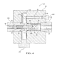
- FIGURE 4 is a schematic cross-sectional illustration of a pressure regulator valve for the hydraulic control system of Figure 1 .
- Figure 1 shows a portion of an engine 10 including a hydraulic control system 12 that controls hydraulic fluid flow to engine valve lift switching components such as rocker arms 14 and lash adjusters 16, and directs fluid flow from an exhaust passage 18 of an oil control valve 20 to drip rails 22 that lubricate other engine components as explained herein.
- a hydraulic control system 12 that controls hydraulic fluid flow to engine valve lift switching components such as rocker arms 14 and lash adjusters 16, and directs fluid flow from an exhaust passage 18 of an oil control valve 20 to drip rails 22 that lubricate other engine components as explained herein.
- the hydraulic control system 12 shown in Figure 1 illustrates control of hydraulic fluid to two oil control valves 20, each affecting fluid flow to a different drip rail 22, rocker arm 14 and lash adjuster 16.
- the drip rails 22 are also referred to herein as elongated tubular members.
- the number of control valves 20, and the number of rocker arms 14 and lash adjusters 16 affected by each control valve 20 depends in part on the timing requirements of the engine 12, and may be different than that shown in the exemplary embodiment of Figure 1 .
- the control valves 20 are part of an oil control valve assembly 24 that also includes a pressure regulator valve 26 and pressure relief valves 28, the function and operation of which are described below.
- the engine 10 has an oil sump 30 containing hydraulic fluid, also referred to herein as oil, that is pressurized and directed through a feed passage 32 by a pump 34.
- oil hydraulic fluid
- cam phaser valves 36 that adjust and retard cam timing based on factors such as engine speed and load. Because the cam phasers 36 intermittently draw fluid from the feed passage 32, pressure in the feed passage 32 varics.
- the pressure regulator valve 26 moderates pressure supplied from the feed passage 32 through the regulator valve 26 to supply passage 40, which feeds into both of the control valves 20.
- the pressure regulator valve 26 is shown and described in further detail with respect to Figure 4 , below.
- Flow through the bypass passage 42 must pass through a restriction 44 (also referred to as a first orifice) dropping the pressure and limiting flow. This, in combination with the regulated pressure, causes a consistent flow rate to the drip rail 22.
- a pressure relief valve 28 is positioned between the bypass passage 42 and the drip rail 22.
- the pressure relief valve 28 permits fluid flow to the drip rail 22 when a sufficient pressure is reached in the bypass passage 42 that will improve actuation speed of the rocker arm 14 and lash adjuster 16, but that is not high enough to cause actuation of the rocker arm 14 and lash adjuster 16. Due to the restriction 44 and deliberate sizing of the passages 40, 42, fluid pressure provided to the supply passage 40 is greater than fluid pressure in the bypass passage 42 downstream of the restriction 44.
- the oil control valve 20 also has a control passage 46 in fluid communication with the rocker arm 14 and lash adjuster 16.
- a valve member 48 of the oil control valve 20 is shown in a position that blocks fluid communication from the supply passage 40 to the control passage 46 so that the rocker arm 14 and lash adjuster 16 are not actuated by the higher fluid pressure in the supply passage 40. Instead, fluid pressure allowed by the relief valve 28 is communicated through passage 42, the control valve 20 and the passage 46 to the rocker arm 14 and lash adjuster 16. Control of the oil control valve 20 and fluid flow to the drip rail 22 is described in greater detail with respect to the embodiments of oil control valve assemblies 24 and 24A of Figures 2 and 3 .
- the oil control valve 20 is shown as a solenoid valve having an electrical coil 50 supported by a coil support portion 52 (also referred to as a bobbin) and covered by a coil cover 53(also referred to as a can).
- the control valve 20 includes a manifold 56 that defines an armature chamber 58 in which a pole piece 60 is fit.
- Manifold 56 defines the supply passage 40, bypass passage 42, exhaust passage 18 and control passage 46. Plugs 61 close off branches within manifold 56 leading to the passages 18 and 42.
- An armature 62 and the valve member 48 connected thereto are movable in the armature chamber 58 in response to energizing of the coil 50.
- a flux collector 64 (also referred to as a flux bracket) is supported adjacent the coil 50 and armature 62 by a-valve body 66 of the manifold 56. Electrical wiring for energizing of the coil 50 may be connected with the coil 50 through wiring openings or through an electrical connector mounted to the coil cover 53, as is known.
- the pole piece 60, can 53, coil 50, armature 62 and flux collector 64 form an electromagnet. Lines of flux are created in an air gap between the pole piece 60 and the armature 48 when the coil 50 is energized by an electric source (such as a battery, not shown).
- the armature 62 moves in response to the flux.
- the coil 50 is energized under the control of an electronic controller (not shown) in response to various engine operating conditions, as is known.
- the armature 62 and valve member 48 are shown in a position in which the coil 50 is not energized, as is Figure 1 . In this position, a first portion 68 of the armature 62 is seated on the base portion 66, while a second portion 70 of the valve member 48 is not seated.
- the pressure relief valve 28 is shown installed within the manifold 56, upstream of the drip rail 22.
- the pressure relief valve 28 is shown closed, but will open when spring-biased ball 72 moves away from valve seat 74 at a sufficient fluid pressure in the exhaust passage 18 that is still lower than the pressure required to actuate the rocker arm 14 and lash adjuster 16.
- When the pressure relief valve 28 opens fluid is supplied to drip rail 22.
- Drip rail 22 is connected to the manifold 56 with a connector 75 press-fit or otherwise secured within the exhaust passage 18. Fluid in the drip rail 22 will gradually drain onto engine components 80 through apertures 82 in the drip rail 22 at a rate dependent on the fluid pressure within the drip rail 22 and the size of the apertures 82.
- the apertures 82 are spaced according to the positions of the engine components 80, which may be cam bearings, gears, or any engine components that benefit from consistent lubrication.
- the drip rail 22 is non-linear with S-shaped curves. This shape helps to keep fluid draining through the apertures 82 from spreading along the outside of the drip rail 22, and instead positions the apertures 82 at low points on the drip rail 22 to encourage fluid to drip onto the engine components 80.
- the drip rail 22 is located above the engine components 80. However, depending on the operating fluid pressure within the drip rail 22, fluid could dispense sideways onto engine components 80, allowing the drip rail 22 to be positioned laterally alongside the engine components 80.
- the drip rail 22 is upturned at a terminal portion 84. If fluid fills the drip rail 22 and rises in the terminal portion 84, it forms a fluid head that helps to maintain pressure in the drip rail 22. The fluid will spill over the open end of the terminal portion of the drip rail 22 into the engine 10 if pressure in the drip rail 22 exceeds a certain level.
- FIG 3 shows an alternate embodiment of an oil control valve assembly 24A that is alike in all aspects to the oil control valve assembly 24 of Figures 1 and 2 , except that a pressure relief valve 28A is repositioned to an end of a slightly modified drip rail 22A.
- the coil 50 is energized, causing the armature 62 and valve member 48 to lift such that the first portion 68 of armature 62 is not seated on the base portion 66 (see Figure 2 ), while the second portion 70 of valve member 48 is seated.
- fluid communication from the fluid supply passage 40 to the control passage 46 through chamber 58 is established.
- the pressure of fluid provided from the supply passage 40 is sufficient to actuate the rocker arms 14 and valve lifters 16.
- valve member 48 While the valve member 48 is in the position shown in Figure 3 , fluid is supplied to the drip rail 22A through the exhaust passage 18 only via the bypass passage 42. Fluid drains through apertures 82A onto the engine components 80 at a rate determined by the fluid pressure within the drip rail 22A and the size of the apertures 82A. At a predetermined fluid pressure within the drip rail 22A, the pressure relief valve 28A will open, draining fluid through opening 84 into the engine 10. Because the pressure relief valve 28A is at the end of the drip rail 22A opposite the exhaust passage 18, fluid in drip rail 22A is pressurized. This helps to ensure fluid flow through the apertures 82A even at low temperatures.
- the pressure regulator valve 26 is shown in greater detail.
- the pressure regulator valve 26 is integrated with oil control valve 20 via a common manifold 56.
- the operative valve member 85 and passages of pressure regulator valve 26 are formed at a different cross-section of manifold 56 spaced from the chamber 48.
- the manifold 56 forms an intake chamber 86 to which fluid flows through an open plug 83 from feed passage 32.
- a base portion 66A of manifold 56 forms a chamber 58A. Fluid communication from the feed passage 32 through the intake chamber 86 and chamber 58A to branches passage 87and 88 leading to the two portions of supply passage 40 is dependent upon the position of the valve member 85 via the chamber 58A.
- Branch passages 87 and 88 are capped by plugs 97A, 97B.
- the valve member 85 is biased by spring 89 toward the open plug 83.
- One end of the spring 89 is held by open plug 91.
- the chamber 58A is fully open to the feed passage 32.
- a stationary cap 95 attached to base portion 66A limits movement of the valve member 85 toward the open plug 83. Any fluid that passes around the valve member 85 will be exhausted to the sump 30 of Figure 1 through tank port 93.
- a chamber 100 is formed between the valve member 85 and the cap 95. As fluid pressure delivered from the feed passage 32 and into chamber 100 increases, a net fluid force acts on the interior surface 90 of the valve member 85, moving the valve member 85 away from the open plug 83, thus restricting communication between the chamber 58A and the intake chamber 86.
- Fluid transmitted through branch passages 87 and 88 to supply passage 40 (a portion of which routes through restriction 44 to supply passage 42) is thus at a lower pressure. If pressure decreases in chamber 100, the valve member 85 moves toward the open plug 83, and oil flow is increased raising the pressure delivered through chamber 58A and branch passages 87 and 88 to supply passage 40 (a portion of which routes through restriction 44 to bypass passage 42) is thus at a higher pressure. In this manner, the pressure regulator valve 26 prevents extreme drops and spikes in fluid pressure to the oil control valve 20 and the drip rail 22 or 22A. By limiting the maximum pressure, the size of the apertures 82 and 82A of drip rails 22 and 22A can be increased, improving flow at low temperatures, especially in the unpressurized drip rail 22. By preventing fluid pressure from falling below a minimum pressure, a consistent residual pressure is maintained at the rocker arms 14 and lash adjusters 16 when these components are not actuated, preventing air from entering the flow passages and reducing actuation time.
Landscapes
- Engineering & Computer Science (AREA)
- Mechanical Engineering (AREA)
- General Engineering & Computer Science (AREA)
- Valve Device For Special Equipments (AREA)
- Valve-Gear Or Valve Arrangements (AREA)
- Lubrication Of Internal Combustion Engines (AREA)
Abstract
Description
- This application claims the benefit of United States Provisional Application No.
61/147,543, filed January 27, 2009 - The invention relates to an oil control valve assembly having an exhaust port operatively connected to a drip rail in an engine.
- Hydraulic control systems for engines are used to control oil under pressure that may be used to switch latch pins in switching lifters, lash adjusters, and rocker arms for cam switching. Valve lifters are engine components that control the opening and closing of exhaust and intake valves in an engine. Rocker arms are used to change the lift profile of camshafts. Lash adjusters may also be used to deactivate or vary exhaust and intake valves in an engine. By varying valve lift, fuel efficiency of an engine may be improved. Camshafts and other rotating, sliding or otherwise movable components within the engine require lubrication. In some engines, fluid is pumped to a drip rail positioned above the components to provide the necessary lubrication.
- An oil control valve assembly for an engine is provided that has a control valve with a valve body which defines both a control passage in fluid communication with a valve lift switching component, such as a switching rocker arm or switching lash adjuster, and an exhaust passage for exhausting fluid from the valve. The control valve is controllable to selectively direct fluid from a supply source to the control passage to actuate the valve lift switching component. An elongated tubular member, such as a drip rail, is positioned adjacent the engine component and is operatively connected to the exhaust passage such that fluid flows from the exhaust passage to the elongated tubular member and through the elongated tubular member onto the engine component. In this manner, oil flow need not be separately directed to the elongated tubular member from the supply source. Oil flow requirements are reduced, thus saving energy.
- The oil control valve assembly may include a pressure relief valve in fluid communication with the exhaust passage that is configured to open when pressure in the exhaust passage reaches a predetermined pressure that is less than a minimum pressure required to actuate the valve lift switching component. The pressure relief valve thus helps to maintain a residual pressure to the valve lift switching component. This prevents air from entering the passages or reaching the valve lift switching components, which would disrupt actuation timing. Maintaining a residual pressure also decreases the time required to raise the pressure level to the minimum pressure required for actuation, thus decreasing actuation response time. The pressure relief valve may be between the exhaust passage and the elongated tubular member, in which case, fluid drips from the elongated tubular member by gravity only. Alternatively, the elongated tubular member may be between the exhaust passage and the pressure relief valve such that fluid within the elongated tubular member is pressurized up to the predetermined pressure at which the relief valve opens. A pressurized elongated tubular member ensures lubrication of the engine components even at low temperatures. Other means of dispensing pressurized oil to lubricate the engine components, such as through squirters in the rocker arms are unnecessary.
- A pressure regulator valve upstream of the control valve may also be provided. The pressure regulator valve is configured to regulate fluid pressure provided to the supply passage and the bypass passage from the supply source. Supply pressure is thus stabilized, making response times more consistent over a variety of temperature and pressure fluctuations in the fluid provided from the supply source. For example, interference caused by fluid demand of other hydraulic valves and components is reduced. Because the maximum pressure is controlled, the apertures in the elongated tubular member can be larger. This is especially beneficial if fluid in the elongated tubular member is not pressurized, as adequate fluid flow through the apertures at low temperatures requires sufficiently large apertures.
- The above features and advantages and other features and advantages of the present invention are readily apparent from the following detailed description of the best modes for carrying out the invention when taken in connection with the accompanying drawings.
-
FIGURE 1 is a schematic representation of an engine with a hydraulic control system; -
FIGURE 2 is a schematic cross-sectional illustration of one embodiment of an oil control valve, pressure relief valve and drip rail for the hydraulic control system ofFigure 1 ; -
FIGURE 3 is a schematic cross-sectional illustration of another embodiment of an oil control valve, pressure relief valve and drip rail for the hydraulic control system ofFigure 1 ; and -
FIGURE 4 is a schematic cross-sectional illustration of a pressure regulator valve for the hydraulic control system ofFigure 1 . - Referring to the drawings, wherein like reference numbers refer to like components throughout the several views,
Figure 1 shows a portion of anengine 10 including a hydraulic control system 12 that controls hydraulic fluid flow to engine valve lift switching components such asrocker arms 14 andlash adjusters 16, and directs fluid flow from anexhaust passage 18 of anoil control valve 20 to driprails 22 that lubricate other engine components as explained herein. - The hydraulic control system 12 shown in
Figure 1 illustrates control of hydraulic fluid to twooil control valves 20, each affecting fluid flow to adifferent drip rail 22,rocker arm 14 andlash adjuster 16. Thedrip rails 22 are also referred to herein as elongated tubular members. The number ofcontrol valves 20, and the number ofrocker arms 14 andlash adjusters 16 affected by eachcontrol valve 20 depends in part on the timing requirements of the engine 12, and may be different than that shown in the exemplary embodiment ofFigure 1 . Thecontrol valves 20 are part of an oilcontrol valve assembly 24 that also includes apressure regulator valve 26 andpressure relief valves 28, the function and operation of which are described below. - The
engine 10 has anoil sump 30 containing hydraulic fluid, also referred to herein as oil, that is pressurized and directed through afeed passage 32 by apump 34. Some of the oil in thefeed passage 32 is used bycam phaser valves 36 that adjust and retard cam timing based on factors such as engine speed and load. Because thecam phasers 36 intermittently draw fluid from thefeed passage 32, pressure in thefeed passage 32 varics. In order to regulate fluid pressure flowing to theoil control valves 20 and avoid extreme fluctuations, thepressure regulator valve 26 moderates pressure supplied from thefeed passage 32 through theregulator valve 26 to supplypassage 40, which feeds into both of thecontrol valves 20. Thepressure regulator valve 26 is shown and described in further detail with respect toFigure 4 , below. - Flow through the
bypass passage 42 must pass through a restriction 44 (also referred to as a first orifice) dropping the pressure and limiting flow. This, in combination with the regulated pressure, causes a consistent flow rate to thedrip rail 22. In the embodiment shown, which is described further with respect toFigure 2 , apressure relief valve 28 is positioned between thebypass passage 42 and thedrip rail 22. Thepressure relief valve 28 permits fluid flow to thedrip rail 22 when a sufficient pressure is reached in thebypass passage 42 that will improve actuation speed of therocker arm 14 andlash adjuster 16, but that is not high enough to cause actuation of therocker arm 14 andlash adjuster 16. Due to therestriction 44 and deliberate sizing of thepassages supply passage 40 is greater than fluid pressure in thebypass passage 42 downstream of therestriction 44. - The
oil control valve 20 also has acontrol passage 46 in fluid communication with therocker arm 14 andlash adjuster 16. InFigure 1 , avalve member 48 of theoil control valve 20 is shown in a position that blocks fluid communication from thesupply passage 40 to thecontrol passage 46 so that therocker arm 14 andlash adjuster 16 are not actuated by the higher fluid pressure in thesupply passage 40. Instead, fluid pressure allowed by therelief valve 28 is communicated throughpassage 42, thecontrol valve 20 and thepassage 46 to therocker arm 14 andlash adjuster 16. Control of theoil control valve 20 and fluid flow to thedrip rail 22 is described in greater detail with respect to the embodiments of oilcontrol valve assemblies Figures 2 and3 . - In
Figure 2 , a portion of the oilcontrol valve assembly 24 ofFigure 1 is shown. Theoil control valve 20 is shown as a solenoid valve having anelectrical coil 50 supported by a coil support portion 52 (also referred to as a bobbin) and covered by a coil cover 53(also referred to as a can). Thecontrol valve 20 includes amanifold 56 that defines anarmature chamber 58 in which apole piece 60 is fit. Manifold 56 defines thesupply passage 40,bypass passage 42,exhaust passage 18 andcontrol passage 46.Plugs 61 close off branches withinmanifold 56 leading to thepassages - An
armature 62 and thevalve member 48 connected thereto are movable in thearmature chamber 58 in response to energizing of thecoil 50. A flux collector 64 (also referred to as a flux bracket) is supported adjacent thecoil 50 andarmature 62 by a-valve body 66 of themanifold 56. Electrical wiring for energizing of thecoil 50 may be connected with thecoil 50 through wiring openings or through an electrical connector mounted to thecoil cover 53, as is known. - The
pole piece 60, can 53,coil 50,armature 62 andflux collector 64 form an electromagnet. Lines of flux are created in an air gap between thepole piece 60 and thearmature 48 when thecoil 50 is energized by an electric source (such as a battery, not shown). Thearmature 62 moves in response to the flux. Thecoil 50 is energized under the control of an electronic controller (not shown) in response to various engine operating conditions, as is known. Thearmature 62 andvalve member 48 are shown in a position in which thecoil 50 is not energized, as isFigure 1 . In this position, afirst portion 68 of thearmature 62 is seated on the base portion 66, while a second portion 70 of thevalve member 48 is not seated. In this position, there is no fluid communication between thesupply passage 40 and thecontrol passage 46. There is fluid communication between theexhaust passage 18 and thecontrol passage 46 throughchamber 58, thus also establishing fluid communication between thebypass passage 42 and thecontrol passage 46. Therocker arms 14 and lashadjusters 16 ofFigure 1 are not actuated by the fluid provided to thecontrol passage 46. - The
pressure relief valve 28 is shown installed within the manifold 56, upstream of thedrip rail 22. Thepressure relief valve 28 is shown closed, but will open when spring-biasedball 72 moves away fromvalve seat 74 at a sufficient fluid pressure in theexhaust passage 18 that is still lower than the pressure required to actuate therocker arm 14 and lashadjuster 16. When thepressure relief valve 28 opens, fluid is supplied todrip rail 22.Drip rail 22 is connected to the manifold 56 with aconnector 75 press-fit or otherwise secured within theexhaust passage 18. Fluid in thedrip rail 22 will gradually drain ontoengine components 80 throughapertures 82 in thedrip rail 22 at a rate dependent on the fluid pressure within thedrip rail 22 and the size of theapertures 82. Theapertures 82 are spaced according to the positions of theengine components 80, which may be cam bearings, gears, or any engine components that benefit from consistent lubrication. - The
drip rail 22 is non-linear with S-shaped curves. This shape helps to keep fluid draining through theapertures 82 from spreading along the outside of thedrip rail 22, and instead positions theapertures 82 at low points on thedrip rail 22 to encourage fluid to drip onto theengine components 80. Preferably thedrip rail 22 is located above theengine components 80. However, depending on the operating fluid pressure within thedrip rail 22, fluid could dispense sideways ontoengine components 80, allowing thedrip rail 22 to be positioned laterally alongside theengine components 80. Thedrip rail 22 is upturned at aterminal portion 84. If fluid fills thedrip rail 22 and rises in theterminal portion 84, it forms a fluid head that helps to maintain pressure in thedrip rail 22. The fluid will spill over the open end of the terminal portion of thedrip rail 22 into theengine 10 if pressure in thedrip rail 22 exceeds a certain level. -
Figure 3 shows an alternate embodiment of an oilcontrol valve assembly 24A that is alike in all aspects to the oilcontrol valve assembly 24 ofFigures 1 and2 , except that a pressure relief valve 28A is repositioned to an end of a slightly modifieddrip rail 22A. InFigure 3 , thecoil 50 is energized, causing thearmature 62 andvalve member 48 to lift such that thefirst portion 68 ofarmature 62 is not seated on the base portion 66 (seeFigure 2 ), while the second portion 70 ofvalve member 48 is seated. Thus, fluid communication from thefluid supply passage 40 to thecontrol passage 46 throughchamber 58 is established. The pressure of fluid provided from thesupply passage 40 is sufficient to actuate therocker arms 14 andvalve lifters 16. - While the
valve member 48 is in the position shown inFigure 3 , fluid is supplied to thedrip rail 22A through theexhaust passage 18 only via thebypass passage 42. Fluid drains throughapertures 82A onto theengine components 80 at a rate determined by the fluid pressure within thedrip rail 22A and the size of theapertures 82A. At a predetermined fluid pressure within thedrip rail 22A, the pressure relief valve 28A will open, draining fluid through opening 84 into theengine 10. Because the pressure relief valve 28A is at the end of thedrip rail 22A opposite theexhaust passage 18, fluid indrip rail 22A is pressurized. This helps to ensure fluid flow through theapertures 82A even at low temperatures. - Referring to
Figure 4 , thepressure regulator valve 26 is shown in greater detail. Thepressure regulator valve 26 is integrated withoil control valve 20 via acommon manifold 56. Theoperative valve member 85 and passages ofpressure regulator valve 26 are formed at a different cross-section ofmanifold 56 spaced from thechamber 48. The manifold 56 forms anintake chamber 86 to which fluid flows through anopen plug 83 fromfeed passage 32. Abase portion 66A ofmanifold 56 forms achamber 58A. Fluid communication from thefeed passage 32 through theintake chamber 86 andchamber 58A tobranches passage 87and 88 leading to the two portions ofsupply passage 40 is dependent upon the position of thevalve member 85 via thechamber 58A.Branch passages 87 and 88 are capped byplugs 97A, 97B. - The
valve member 85 is biased byspring 89 toward theopen plug 83. One end of thespring 89 is held by open plug 91. When thespring 89 is in an extended position, thechamber 58A is fully open to thefeed passage 32. A stationary cap 95 attached tobase portion 66A limits movement of thevalve member 85 toward theopen plug 83. Any fluid that passes around thevalve member 85 will be exhausted to thesump 30 ofFigure 1 throughtank port 93. Achamber 100 is formed between thevalve member 85 and the cap 95. As fluid pressure delivered from thefeed passage 32 and intochamber 100 increases, a net fluid force acts on theinterior surface 90 of thevalve member 85, moving thevalve member 85 away from theopen plug 83, thus restricting communication between thechamber 58A and theintake chamber 86. Fluid transmitted throughbranch passages 87 and 88 to supply passage 40 (a portion of which routes throughrestriction 44 to supply passage 42) is thus at a lower pressure. If pressure decreases inchamber 100, thevalve member 85 moves toward theopen plug 83, and oil flow is increased raising the pressure delivered throughchamber 58A andbranch passages 87 and 88 to supply passage 40 (a portion of which routes throughrestriction 44 to bypass passage 42) is thus at a higher pressure. In this manner, thepressure regulator valve 26 prevents extreme drops and spikes in fluid pressure to theoil control valve 20 and thedrip rail apertures unpressurized drip rail 22. By preventing fluid pressure from falling below a minimum pressure, a consistent residual pressure is maintained at therocker arms 14 and lashadjusters 16 when these components are not actuated, preventing air from entering the flow passages and reducing actuation time. - While the best modes for carrying out the invention have been described in detail, those familiar with the art to which this invention relates will recognize various alternative designs and embodiments for practicing the invention within the scope of the appended claims.
Claims (15)
- An oil control valve assembly (24, 24A) for an engine (10) with an engine component (80) and a valve lift switching component (14, 16), comprising:a control valve (20) having a manifold (56) defining a control passage (46) in fluid communication with the valve lift switching component and an exhaust passage (18) for exhausting fluid from the valve; wherein the control valve is controllable to selectively direct fluid from a supply source (30) to the control passage to actuate the valve lift switching component;wherein the control valve (20) further has a bypass passage (42) with a restriction (44) that is in fluid communication with the exhaust passage, wherein fluid flows from the supply source through the restriction and the bypass passage to the exhaust passage such that the fluid undergoes a pressure drop when it flows through the restriction, fluid flowing to the exhaust passage and the elongated tubular member from the bypass passage thereby being lower in pressure than fluid flowing from the supply passage to the control passage;an elongated tubular member (22, 22A) positioned adjacent the engine component and operatively connected to the exhaust passage such that fluid flows from the exhaust passage to the elongated tubular member and through the elongated tubular member onto the engine component; anda pressure regulator valve (26) configured to regulate fluid pressure provided to the supply passage and the bypass passage from the supply source.
- The control valve assembly of Claim 1, further comprising a pressure relief valve (28, 28A) in fluid communication with the exhaust passage and configured to open when pressure in the exhaust passage reaches a predetermined pressure that is less than a minimum pressure required to actuate the valve lift switching component.
- The control valve assembly of claim 1, wherein the exhaust passage is in fluid communication with the control passage when the control valve does not direct fluid from the supply passage to the control passage.
- An oil control valve assembly (24, 24A) for an engine (10) with a fluid source, at least one engine component (80), and at least one engine valve lift switching component (14, 16), comprising:a solenoid valve (20) having a valve member (48) and a manifold (56); wherein the manifold defines a supply passage (40), a bypass passage (42) with a restriction (44), a control passage (46), and an exhaust passage (18); wherein fluid from the fluid source is supplied in parallel to both the supply passage and the bypass passage, with the fluid undergoing a pressure drop through the restriction to a pressure in the bypass passage less than a minimum pressure required to actuate the at least one engine valve lift switching component; wherein the valve member is movable from a first position in which fluid is communicated from the supply passage to the control passage to actuate the at least one engine valve lift switching component, to a second position in which fluid is not communicated from the supply passage to the control passage; wherein the bypass passage is in fluid communication with the exhaust passage regardless of the position of the valve member; andan elongated tubular member (22, 22A) in fluid communication with the exhaust passage and having at least one aperture (82, 82A) positioned such that fluid in the elongated tubular member flows through the at least one aperture onto the at least one engine component.
- The oil control valve assembly of claim 4, further comprising a pressure relief valve (28, 28A) downstream of the exhaust passage and operable to relieve pressure in the exhaust passage at a predetermined pressure.
- The oil control valve assembly of claim 5, wherein the pressure relief valve (28) is between the exhaust passage and the elongated tubular member (22), and wherein a terminal portion (84) of the elongated tubular member is configured to form a fluid head within the elongated tubular member.
- The oil control valve of claim 5, wherein the elongated tubular member (22A) is between the exhaust passage and the pressure relief valve (28A) such that fluid pressure within the elongated tubular member is pressurized to a pressure that does not exceed the predetermined pressure.
- The oil control valve assembly of claim 5, wherein fluid is communicated from the bypass passage to the control passage through the exhaust passage when the valve member is in the second position; and wherein the predetermined pressure is less than a minimum pressure required to actuate the at least one engine valve switching component.
- The oil control valve assembly of claim 4, further comprising:a pressure regulator valve (26) upstream of the solenoid valve and configured to regulate fluid pressure provided to the supply passage and the bypass passage from the pressure source.
- The oil control valve assembly of claim 4, wherein the elongated tubular member (22, 22A) is non-linear.
- A hydraulic control system (12) for an engine (10) with engine components (80) and engine valve lift switching components (14, 16), comprising:an oil control valve assembly (24, 24A) havinga solenoid valve (20) with a valve member (48) and a valve body (66); wherein the valve body defines a chamber (58) in which the valve member is movable;a manifold (56) that definesa supply passage (40);a bypass passage (42) bypassing the valve member and having a restriction (44);a control passage (46) in fluid communication with the engine valve lift switching components; andan exhaust passage (18); wherein fluid communication from the supply passage to the control passage and from the exhaust passage to the control passage is dependent on the position of the valve member; wherein the bypass passage is in fluid communication with the exhaust passage regardless of the position of the solenoid valve;wherein the solenoid valve is energizable and deenergizable to move the valve member to different positions within the chamber and thereby alternately establish fluid communication between the supply passage and the control passage and between the exhaust passage and the control passage;wherein the supply passage is in fluid communication with the control passage when the position of the valve member is such that the valve member blocks fluid communication from the chamber to the exhaust passage; wherein the supply passage is not in fluid communication with the control passage when the position of the valve member is such that the valve member does not block fluid communication between the chamber and the exhaust passage;wherein the exhaust passage is in fluid communication with the control passage when the valve member does not block fluid communication between the chamber and the exhaust passage;an elongated tubular member (22, 22A) extending from the exhaust passage and having spaced apertures (82, 82A); and wherein fluid is provided to the tubular member through the restriction and the bypass passage at a pressure less than the supply pressure, and is provided from the tubular member through the spaced apertures onto the engine components for lubrication thereof.
- The hydraulic control system of claim 11, further comprising:a pressure relief valve (28, 28A) downstream of the exhaust passage and configured to open when pressure in the exhaust passage reaches a predetermined pressure less than a minimum pressure required to actuate the engine valve lift switching components.
- The hydraulic control system of claim 12, wherein the pressure relief valve (28) is between the exhaust passage and the tubular member (22), and wherein a terminal portion (84) of the tubular member is configured to form a fluid head within the tubular member.
- The hydraulic control system of claim 12, wherein the tubular member (22A) is between the exhaust passage and the pressure relief valve (28A) such that fluid pressure within the tubular member is controlled to a pressure not greater than the predetermined pressure.
- The hydraulic control system of claim 11, further comprising:a pressure source (34); anda pressure regulator valve (26) upstream of the solenoid valve and configured to regulate fluid pressure provided to the supply passage and the bypass passage from the pressure source.
Priority Applications (2)
| Application Number | Priority Date | Filing Date | Title |
|---|---|---|---|
| PL13161721T PL2610447T3 (en) | 2009-01-27 | 2010-01-26 | Oil control valve assembly for engine cam switching |
| EP13161721.9A EP2610447B1 (en) | 2009-01-27 | 2010-01-26 | Oil control valve assembly for engine cam switching |
Applications Claiming Priority (3)
| Application Number | Priority Date | Filing Date | Title |
|---|---|---|---|
| US14754309P | 2009-01-27 | 2009-01-27 | |
| US12/692,865 US8302570B2 (en) | 2009-01-27 | 2010-01-25 | Oil control valve assembly for engine cam switching |
| EP10707707.5A EP2401482B1 (en) | 2009-01-27 | 2010-01-26 | Oil control valve assembly for engine cam switching |
Related Parent Applications (2)
| Application Number | Title | Priority Date | Filing Date |
|---|---|---|---|
| EP10707707.5A Division-Into EP2401482B1 (en) | 2009-01-27 | 2010-01-26 | Oil control valve assembly for engine cam switching |
| EP10707707.5 Division | 2010-01-26 |
Related Child Applications (2)
| Application Number | Title | Priority Date | Filing Date |
|---|---|---|---|
| EP13161721.9A Division EP2610447B1 (en) | 2009-01-27 | 2010-01-26 | Oil control valve assembly for engine cam switching |
| EP13161721.9 Division-Into | 2013-03-28 |
Publications (2)
| Publication Number | Publication Date |
|---|---|
| EP2568133A2 true EP2568133A2 (en) | 2013-03-13 |
| EP2568133A3 EP2568133A3 (en) | 2013-05-22 |
Family
ID=42353129
Family Applications (3)
| Application Number | Title | Priority Date | Filing Date |
|---|---|---|---|
| EP12195727.8A Withdrawn EP2568133A3 (en) | 2009-01-27 | 2010-01-26 | Oil control valve assembly for engine cam switching |
| EP13161721.9A Not-in-force EP2610447B1 (en) | 2009-01-27 | 2010-01-26 | Oil control valve assembly for engine cam switching |
| EP10707707.5A Not-in-force EP2401482B1 (en) | 2009-01-27 | 2010-01-26 | Oil control valve assembly for engine cam switching |
Family Applications After (2)
| Application Number | Title | Priority Date | Filing Date |
|---|---|---|---|
| EP13161721.9A Not-in-force EP2610447B1 (en) | 2009-01-27 | 2010-01-26 | Oil control valve assembly for engine cam switching |
| EP10707707.5A Not-in-force EP2401482B1 (en) | 2009-01-27 | 2010-01-26 | Oil control valve assembly for engine cam switching |
Country Status (7)
| Country | Link |
|---|---|
| US (2) | US8302570B2 (en) |
| EP (3) | EP2568133A3 (en) |
| JP (1) | JP5582317B2 (en) |
| KR (1) | KR101621121B1 (en) |
| CN (2) | CN201650396U (en) |
| PL (2) | PL2610447T3 (en) |
| WO (1) | WO2010088201A1 (en) |
Families Citing this family (6)
| Publication number | Priority date | Publication date | Assignee | Title |
|---|---|---|---|---|
| US8302570B2 (en) * | 2009-01-27 | 2012-11-06 | Eaton Corporation | Oil control valve assembly for engine cam switching |
| CN102644494A (en) * | 2012-05-12 | 2012-08-22 | 中国兵器工业集团第七0研究所 | Novel lubricating oil circuit for valve mechanism of diesel engine |
| US9506382B2 (en) * | 2015-03-30 | 2016-11-29 | Caterpillar Inc. | Variable valve actuator |
| US10830364B2 (en) | 2015-05-05 | 2020-11-10 | Eaton Intelligent Power Limited | Oil controlled valve |
| CN105972253B (en) * | 2016-07-09 | 2017-02-08 | 常熟骏驰科技有限公司 | Oil pressure regulation valve |
| US10323579B2 (en) * | 2016-12-21 | 2019-06-18 | Caterpillar Inc. | Variable valve actuator having low-pressure relief |
Family Cites Families (26)
| Publication number | Priority date | Publication date | Assignee | Title |
|---|---|---|---|---|
| JPS608407A (en) * | 1983-06-29 | 1985-01-17 | Honda Motor Co Ltd | Internal combustion engine valve actuation control device |
| US4627272A (en) | 1984-11-28 | 1986-12-09 | Cambridge Applied Systems, Inc. | Viscometer |
| US4762000A (en) | 1986-10-06 | 1988-08-09 | Bond Jr Charles R | Fluid level indicating apparatus |
| JPS63167014A (en) * | 1986-12-26 | 1988-07-11 | Honda Motor Co Ltd | Hydraulic circuit of valve action time control device of internal combustion engine |
| US4858574A (en) * | 1986-12-26 | 1989-08-22 | Honda Giken Kogyo Kabushiki Kaisha | Hydraulic circuit for a valve operating timing control device for an internal combustion engine |
| JPS63167012A (en) * | 1986-12-27 | 1988-07-11 | Honda Motor Co Ltd | Hydraulic circuit of valve system for internal combustion engine |
| CA1331547C (en) * | 1988-08-01 | 1994-08-23 | Yukihiro Matsumoto | Valve operating system for internal combustion engine |
| WO1991013322A1 (en) | 1990-02-26 | 1991-09-05 | Caterpillar Industrial Inc. | An apparatus for determining the level of liquid in a container |
| DE4125588C2 (en) | 1991-08-02 | 1998-02-05 | Renk Ag | Oil level gauge |
| JPH10103035A (en) * | 1996-09-24 | 1998-04-21 | Toyota Motor Corp | Oil supply device for internal combustion engine |
| DE19751901A1 (en) | 1996-11-29 | 1998-06-04 | Volkswagen Ag | Automotive engine rocker valve lubricating system |
| DE19902991C1 (en) | 1999-01-26 | 2000-07-06 | Mar Tec Marine Gmbh | Mineral oil temperature-dependent viscosity and viscosity index are determined from damping of excited magnetostrictive rod at differing temperatures to assure e.g. marine engine oil is fit for purpose |
| JP2001336405A (en) * | 2000-05-26 | 2001-12-07 | Jidosha Buhin Kogyo Co Ltd | Engine decompression device |
| DE10242959A1 (en) | 2002-04-26 | 2003-11-06 | Continental Teves Ag & Co Ohg | Brake fluid viscosity determination method in which an inductive fluid level measuring device is used to force the float into the fluid with the float velocity and coil current measured to determine the fluid viscosity |
| JP4211352B2 (en) * | 2002-10-22 | 2009-01-21 | アイシン精機株式会社 | Engine oil supply device |
| US6832587B2 (en) | 2003-01-28 | 2004-12-21 | Dana Corporation | Plastic valve cover with integrated metal |
| JP4260053B2 (en) | 2004-03-26 | 2009-04-30 | Ntn株式会社 | Oil check sensor |
| JP4327681B2 (en) | 2004-08-04 | 2009-09-09 | トヨタ自動車株式会社 | Resin cylinder head cover |
| JP4432664B2 (en) * | 2004-08-10 | 2010-03-17 | トヨタ自動車株式会社 | Lubricating device for internal combustion engine |
| JP2006105038A (en) * | 2004-10-06 | 2006-04-20 | Hitachi Ltd | Lubricating oil supply device for internal combustion engine |
| JP4327704B2 (en) | 2004-11-24 | 2009-09-09 | トヨタ自動車株式会社 | Cylinder head cover |
| JP2007187135A (en) | 2006-01-16 | 2007-07-26 | Toyota Motor Corp | Valve operating device for internal combustion engine |
| US8746408B2 (en) | 2006-09-01 | 2014-06-10 | GM Global Technology Operations LLC | Engine oil change detection systems and methods |
| MX2009010918A (en) | 2007-04-11 | 2009-10-29 | Eaton Corp | Integrated oil condition and level sensor. |
| US7513226B2 (en) * | 2007-06-01 | 2009-04-07 | Gm Global Technology Operations, Inc. | Hydraulic control system for a switching valve train |
| US8302570B2 (en) * | 2009-01-27 | 2012-11-06 | Eaton Corporation | Oil control valve assembly for engine cam switching |
-
2010
- 2010-01-25 US US12/692,865 patent/US8302570B2/en not_active Expired - Fee Related
- 2010-01-26 EP EP12195727.8A patent/EP2568133A3/en not_active Withdrawn
- 2010-01-26 KR KR1020117019487A patent/KR101621121B1/en not_active Expired - Fee Related
- 2010-01-26 EP EP13161721.9A patent/EP2610447B1/en not_active Not-in-force
- 2010-01-26 PL PL13161721T patent/PL2610447T3/en unknown
- 2010-01-26 WO PCT/US2010/022065 patent/WO2010088201A1/en not_active Ceased
- 2010-01-26 EP EP10707707.5A patent/EP2401482B1/en not_active Not-in-force
- 2010-01-26 JP JP2011548211A patent/JP5582317B2/en not_active Expired - Fee Related
- 2010-01-26 PL PL10707707T patent/PL2401482T3/en unknown
- 2010-01-27 CN CN2010201494326U patent/CN201650396U/en not_active Expired - Lifetime
- 2010-01-27 CN CN2010101382556A patent/CN101922324B/en not_active Expired - Fee Related
-
2012
- 2012-09-05 US US13/603,936 patent/US8656873B2/en not_active Expired - Fee Related
Non-Patent Citations (1)
| Title |
|---|
| None |
Also Published As
| Publication number | Publication date |
|---|---|
| US8656873B2 (en) | 2014-02-25 |
| KR20110118692A (en) | 2011-10-31 |
| US20100186696A1 (en) | 2010-07-29 |
| EP2610447A1 (en) | 2013-07-03 |
| PL2401482T3 (en) | 2015-05-29 |
| US8302570B2 (en) | 2012-11-06 |
| CN101922324A (en) | 2010-12-22 |
| EP2568133A3 (en) | 2013-05-22 |
| WO2010088201A1 (en) | 2010-08-05 |
| EP2610447B1 (en) | 2014-08-27 |
| JP2012516412A (en) | 2012-07-19 |
| CN201650396U (en) | 2010-11-24 |
| KR101621121B1 (en) | 2016-05-13 |
| CN101922324B (en) | 2013-05-15 |
| JP5582317B2 (en) | 2014-09-03 |
| EP2401482B1 (en) | 2014-12-10 |
| EP2401482A1 (en) | 2012-01-04 |
| AU2010208408A1 (en) | 2011-08-18 |
| PL2610447T3 (en) | 2015-02-27 |
| US20130000574A1 (en) | 2013-01-03 |
Similar Documents
| Publication | Publication Date | Title |
|---|---|---|
| US8656873B2 (en) | Oil control valve assembly for engine cam switching | |
| EP3853450B1 (en) | Improved response time in lost motion valvetrains | |
| US8327750B2 (en) | Valvetrain oil control system and oil control valve | |
| US5085181A (en) | Electro/hydraulic variable valve timing system | |
| KR20070054587A (en) | Hydraulic pump with variable flow and variable pressure and electrical controls | |
| EP3260672B1 (en) | An engine assembly | |
| KR20110063148A (en) | Electro-Hydraulic Variable Valve Lift Device | |
| EP3287615A1 (en) | A method of regulating oil pressure within an engine assembly | |
| AU2010208408B2 (en) | Oil control valve assembly for engine cam switching | |
| CN101315038B (en) | Hydraulic control system for a switching valve train | |
| KR101813725B1 (en) | Variable valve timing apparatus | |
| KR101028554B1 (en) | Oil circuit for continuous variable valve timing device | |
| US6810845B1 (en) | Lubrication system using valves to meet various engine oil pressure requirements | |
| US6920850B2 (en) | Engine lubrication system | |
| KR20160039024A (en) | Variable valve lift system | |
| US7555999B2 (en) | Cold temperature operation for added motion valve system | |
| US20120272932A1 (en) | Fluid pressure control valve | |
| KR20040107689A (en) | valve lift adjusting apparatus of an engine | |
| CN113167135A (en) | Oil supply system for a hydraulic tappet for compensating valve play | |
| CA2052610A1 (en) | Electro/hydraulic variable valve timing system |
Legal Events
| Date | Code | Title | Description |
|---|---|---|---|
| PUAI | Public reference made under article 153(3) epc to a published international application that has entered the european phase |
Free format text: ORIGINAL CODE: 0009012 |
|
| 17P | Request for examination filed |
Effective date: 20121206 |
|
| AC | Divisional application: reference to earlier application |
Ref document number: 2401482 Country of ref document: EP Kind code of ref document: P |
|
| AK | Designated contracting states |
Kind code of ref document: A2 Designated state(s): AT BE BG CH CY CZ DE DK EE ES FI FR GB GR HR HU IE IS IT LI LT LU LV MC MK MT NL NO PL PT RO SE SI SK SM TR |
|
| PUAL | Search report despatched |
Free format text: ORIGINAL CODE: 0009013 |
|
| AK | Designated contracting states |
Kind code of ref document: A3 Designated state(s): AT BE BG CH CY CZ DE DK EE ES FI FR GB GR HR HU IE IS IT LI LT LU LV MC MK MT NL NO PL PT RO SE SI SK SM TR |
|
| RIC1 | Information provided on ipc code assigned before grant |
Ipc: F01M 9/08 20060101ALI20130415BHEP Ipc: F01L 13/00 20060101ALI20130415BHEP Ipc: F01M 9/10 20060101AFI20130415BHEP Ipc: F01L 1/24 20060101ALI20130415BHEP |
|
| RIN1 | Information on inventor provided before grant (corrected) |
Inventor name: BURESH, LEO JOSEPH III Inventor name: BOYCHUK, ROBERT J. Inventor name: BENEKER, GERRIT V. Inventor name: KELLER, ROBERT DEAN |
|
| 17Q | First examination report despatched |
Effective date: 20160205 |
|
| GRAP | Despatch of communication of intention to grant a patent |
Free format text: ORIGINAL CODE: EPIDOSNIGR1 |
|
| STAA | Information on the status of an ep patent application or granted ep patent |
Free format text: STATUS: GRANT OF PATENT IS INTENDED |
|
| INTG | Intention to grant announced |
Effective date: 20180718 |
|
| STAA | Information on the status of an ep patent application or granted ep patent |
Free format text: STATUS: THE APPLICATION IS DEEMED TO BE WITHDRAWN |
|
| 18D | Application deemed to be withdrawn |
Effective date: 20181129 |