EP2568125A2 - Turbine casing assembly mounting pin - Google Patents
Turbine casing assembly mounting pin Download PDFInfo
- Publication number
- EP2568125A2 EP2568125A2 EP12182829A EP12182829A EP2568125A2 EP 2568125 A2 EP2568125 A2 EP 2568125A2 EP 12182829 A EP12182829 A EP 12182829A EP 12182829 A EP12182829 A EP 12182829A EP 2568125 A2 EP2568125 A2 EP 2568125A2
- Authority
- EP
- European Patent Office
- Prior art keywords
- casing
- pin
- turbine
- diameter
- outer casing
- Prior art date
- Legal status (The legal status is an assumption and is not a legal conclusion. Google has not performed a legal analysis and makes no representation as to the accuracy of the status listed.)
- Withdrawn
Links
- 238000000034 method Methods 0.000 claims abstract description 15
- 230000000712 assembly Effects 0.000 description 4
- 238000000429 assembly Methods 0.000 description 4
- 125000006850 spacer group Chemical group 0.000 description 4
- 239000007789 gas Substances 0.000 description 3
- 230000003116 impacting effect Effects 0.000 description 3
- 241000237503 Pectinidae Species 0.000 description 2
- 238000003491 array Methods 0.000 description 2
- 230000009286 beneficial effect Effects 0.000 description 2
- 230000008901 benefit Effects 0.000 description 2
- 239000000463 material Substances 0.000 description 2
- 238000012986 modification Methods 0.000 description 2
- 230000004048 modification Effects 0.000 description 2
- 235000020637 scallop Nutrition 0.000 description 2
- 229910045601 alloy Inorganic materials 0.000 description 1
- 239000000956 alloy Substances 0.000 description 1
- 230000015556 catabolic process Effects 0.000 description 1
- 239000000919 ceramic Substances 0.000 description 1
- 230000008859 change Effects 0.000 description 1
- 239000000567 combustion gas Substances 0.000 description 1
- 238000004891 communication Methods 0.000 description 1
- 230000003247 decreasing effect Effects 0.000 description 1
- 238000006731 degradation reaction Methods 0.000 description 1
- 230000000694 effects Effects 0.000 description 1
- 230000005484 gravity Effects 0.000 description 1
- 238000012423 maintenance Methods 0.000 description 1
- 230000007246 mechanism Effects 0.000 description 1
- 230000008439 repair process Effects 0.000 description 1
- 238000012552 review Methods 0.000 description 1
- 229910000601 superalloy Inorganic materials 0.000 description 1
- 238000012360 testing method Methods 0.000 description 1
- 230000001052 transient effect Effects 0.000 description 1
Images




Classifications
-
- F—MECHANICAL ENGINEERING; LIGHTING; HEATING; WEAPONS; BLASTING
- F01—MACHINES OR ENGINES IN GENERAL; ENGINE PLANTS IN GENERAL; STEAM ENGINES
- F01D—NON-POSITIVE DISPLACEMENT MACHINES OR ENGINES, e.g. STEAM TURBINES
- F01D25/00—Component parts, details, or accessories, not provided for in, or of interest apart from, other groups
- F01D25/24—Casings; Casing parts, e.g. diaphragms, casing fastenings
- F01D25/243—Flange connections; Bolting arrangements
-
- F—MECHANICAL ENGINEERING; LIGHTING; HEATING; WEAPONS; BLASTING
- F01—MACHINES OR ENGINES IN GENERAL; ENGINE PLANTS IN GENERAL; STEAM ENGINES
- F01D—NON-POSITIVE DISPLACEMENT MACHINES OR ENGINES, e.g. STEAM TURBINES
- F01D25/00—Component parts, details, or accessories, not provided for in, or of interest apart from, other groups
- F01D25/24—Casings; Casing parts, e.g. diaphragms, casing fastenings
- F01D25/246—Fastening of diaphragms or stator-rings
-
- F—MECHANICAL ENGINEERING; LIGHTING; HEATING; WEAPONS; BLASTING
- F01—MACHINES OR ENGINES IN GENERAL; ENGINE PLANTS IN GENERAL; STEAM ENGINES
- F01D—NON-POSITIVE DISPLACEMENT MACHINES OR ENGINES, e.g. STEAM TURBINES
- F01D25/00—Component parts, details, or accessories, not provided for in, or of interest apart from, other groups
- F01D25/24—Casings; Casing parts, e.g. diaphragms, casing fastenings
- F01D25/26—Double casings; Measures against temperature strain in casings
-
- F—MECHANICAL ENGINEERING; LIGHTING; HEATING; WEAPONS; BLASTING
- F01—MACHINES OR ENGINES IN GENERAL; ENGINE PLANTS IN GENERAL; STEAM ENGINES
- F01D—NON-POSITIVE DISPLACEMENT MACHINES OR ENGINES, e.g. STEAM TURBINES
- F01D25/00—Component parts, details, or accessories, not provided for in, or of interest apart from, other groups
- F01D25/28—Supporting or mounting arrangements, e.g. for turbine casing
-
- F—MECHANICAL ENGINEERING; LIGHTING; HEATING; WEAPONS; BLASTING
- F05—INDEXING SCHEMES RELATING TO ENGINES OR PUMPS IN VARIOUS SUBCLASSES OF CLASSES F01-F04
- F05D—INDEXING SCHEME FOR ASPECTS RELATING TO NON-POSITIVE-DISPLACEMENT MACHINES OR ENGINES, GAS-TURBINES OR JET-PROPULSION PLANTS
- F05D2230/00—Manufacture
- F05D2230/60—Assembly methods
- F05D2230/64—Assembly methods using positioning or alignment devices for aligning or centring, e.g. pins
- F05D2230/644—Assembly methods using positioning or alignment devices for aligning or centring, e.g. pins for adjusting the position or the alignment, e.g. wedges or eccenters
-
- F—MECHANICAL ENGINEERING; LIGHTING; HEATING; WEAPONS; BLASTING
- F05—INDEXING SCHEMES RELATING TO ENGINES OR PUMPS IN VARIOUS SUBCLASSES OF CLASSES F01-F04
- F05D—INDEXING SCHEME FOR ASPECTS RELATING TO NON-POSITIVE-DISPLACEMENT MACHINES OR ENGINES, GAS-TURBINES OR JET-PROPULSION PLANTS
- F05D2260/00—Function
- F05D2260/30—Retaining components in desired mutual position
-
- Y—GENERAL TAGGING OF NEW TECHNOLOGICAL DEVELOPMENTS; GENERAL TAGGING OF CROSS-SECTIONAL TECHNOLOGIES SPANNING OVER SEVERAL SECTIONS OF THE IPC; TECHNICAL SUBJECTS COVERED BY FORMER USPC CROSS-REFERENCE ART COLLECTIONS [XRACs] AND DIGESTS
- Y10—TECHNICAL SUBJECTS COVERED BY FORMER USPC
- Y10T—TECHNICAL SUBJECTS COVERED BY FORMER US CLASSIFICATION
- Y10T29/00—Metal working
- Y10T29/49—Method of mechanical manufacture
- Y10T29/49316—Impeller making
- Y10T29/4932—Turbomachine making
Definitions
- the present invention generally involves a turbine casing assembly mounting pin and method for utilizing the same.
- a mounting pin joins an inner casing with an outer casing in a manner that reduces distortion and eccentricity between the inner and outer casings while transferring torque and gravity loads.
- Conventional turbine casings generally include one or more outer turbine casings that surround one or more inner turbine casings.
- the outer turbine casing is often split into two hemispherical casings bolted together by flanges on a horizontal plane to facilitate maintenance and repair.
- the inner turbine casing is often supported through to the outer turbine casing by one or more axially spaced circumferential arrays of pins
- active clearance controls are employed to radially displace inner and outer turbine casings from one another during transient turbine operations. This has the effect of controlling tip clearance between buckets and shrouds, which can be beneficial since decreasing tip clearance improves turbine performance by reducing tip leakage as long as bucket tips are prevented from transiently contacting and thereby rubbing shrouds.
- pins that allow for mounting of an inner turbine casing with an outer turbine casing without impacting outer turbine casing bolt spacing. Methods relating to such pins would also be beneficial.
- a turbine casing assembly in a first aspect of the present invention, includes an inner casing and an outer casing surrounding the inner casing.
- the outer casing includes a first outer casing section and a second outer casing section that join together along a flange.
- Two bolts extend through the flange and join together the first outer casing section and the second outer casing section.
- a pin having a first segment having a first diameter and a second segment having a second diameter extends through the inner casing and the outer casing and supports the inner casing relative to the outer casing.
- the pin has a first diameter that is greater than the second diameter and is located between the two bolts along the axis of the flange.
- a turbine in other aspect of the present invention, includes the above turbine casing assembly wherein the inner casing carries nozzles and shrouds, the shrouds surrounding tips of buckets carried by a turbine rotor within the inner casing.
- a method for assembling a turbine casing includes joining together an inner casing and an outer casing with a pin, the pin including a first segment having a first diameter and a second segment having a second diameter. The first diameter is greater than the second diameter, the pin extending through the inner casing and the outer casing.
- the method includes joining together a first outer casing section and a second outer casing section with two bolts, the pin being located between the two bolts.
- the method also includes surrounding the inner casing with the outer casing.
- FIG. 1 there is illustrated a turbine casing assembly 10 cross-section, having an outer structural casing 12 and an inner casing 14 supported by the outer casing 12.
- the inner casing 14 carries an array of nozzles 16 and 18 forming parts of first and second stages, respectively, of the turbine.
- the inner casing 14 also surrounds a rotor, generally designated 20, rotatable about an axis 22.
- the rotor 20 includes circumferential arrays of buckets mounted on wheels arranged alternately with spacers, the wheels and spacers forming the body of the rotor.
- the first and second-stage wheels 24 and 26 with an intervening spacer 28 are illustrated, the wheels 24 and 26 mounting buckets 28 and 30, respectively.
- the buckets and the nozzles of the various stages in part define the annular hot gas path through the turbine.
- the wheels and spacers of the rotor are secured to one another by bolts 32 circumferentially spaced one from the other about the rotor.
- FIG. 2 illustrates a schematic end view of an assembly 10 according to one embodiment of the present disclosure.
- the turbine assembly 10 generally includes one or more inner casings 14 and one or more outer casings 12.
- the one or more inner casings 14 and outer casings 12 are typically fabricated from alloys, superalloys, coated ceramics, or other material capable of withstanding temperatures associated with turbines.
- a casing for a turbine in a gas turbine system would be fabricated from materials capable of withstanding temperatures associated with nozzle and shroud hook temperatures which are driven by among other factors combustion gases flowing through the gas turbine system.
- the inner casing 14 comprises a forward section 36 and an aft section 38 interconnected by an axially extending annular rib 40.
- the forward and aft sections 36 and 38 are annular and have radially inwardly directed dovetails 42 and 44, respectively, for carrying shrouds 46 and 48.
- the shrouds provide a minimum clearance with the tips of the buckets. It will be appreciated that the inner casing 14 is secured to the outer casing along radial planes normal to the axis of the rotor and at axial locations, preferably in alignment with the first and second-stage buckets and shrouds.
- the outer casing 14 generally surrounds the one or more inner casings 12 and together form the turbine 10. In this manner, the inner casings 12 generally conform to the outer perimeter of the rotating component, and the outer casing 14 provides an enclosure around the rotating component.
- Bolts 50 secure the upper and lower outer casing casings 125 and 126 to one another along a flange 52 that can extend across a section of the horizontal midline on either side of the turbine 10.
- Bolts refers to any structures such as a bolts, studs, pins, or the like that are positioned in flange bolt opening.
- one or more pin assemblies 54 pass through the outer casing 12 for connection with the inner casing 14.
- the pin assemblies can pass through flange 52 of outer casing 12.
- One or more pin assemblies 54 can be spaced along each flange 52 that extends across a section of the horizontal midline on either side of the turbine 10.
- the pin assembly 54 includes an inner pin portion 56 and an outer pin portion 58.
- the inner bore of the outer pin is eccentric to the outer diameter of the outer pin. This allows for the outer pin to be rotated and thus change the centerline location of the inner pin. Eccentric pins are often used in turbine systems to allow for precise external alignment capability of the inner casing relative to the rotor.
- Inner pin portion 56 includes an expanded ledge 60 on the radial innermost end 62 of the inner pin portion 56.
- Ledge 60 can have a generally square shape that interfaces with a complimentary female receiver defined by inner shell (shown in FIG. 2 ).
- Bolt section 64 extends from ledge 60 and can be generally cylindrical in shape.
- Bolt section 64 can include one or more contact pads 70 which allow for deterministic loading with outer pin portion 58.
- Bolt section 64 includes a section 66 having smaller diameter to accommodate pin assembly 54 being located between two bolts as will be further described herein.
- the outermost end 67 of inner pin portion 56 can define threads to receive an inner nut 68.
- Outer pin portion 58 includes an enlarged head 71 having a bolt circle 72 with one or more circumferentially defined bolt openings 74.
- Bolt circle further defines an opening 80 that outermost end 67 of inner pin portion 56 can extend through.
- the bolt openings can be configured to receive one or more bolts 76 that react out pin rotation through friction which can set alignment of inner and outer turbine casings.
- Alignment portion 78 extends from bolt circle 72 and defines an opening (not shown) in communication with bolt circle opening 80 which can receive inner pin portion and also allow for outer pin rotations after assembly within the alignment requirements of the unit.
- Alignment portion includes contact pads 84 that allow deterministic loading with the inner and outer turbine casings and which are generally aligned with contact pads 70 of inner pin portion.
- Alignment portion includes one or more alignment scallops 82 which permit pin assembly 54 to be located between two bolts as will be further described herein.
- Alignment scallops 82 are defined, in part, by ridge portions 85 that each have a width that is approximately the same as or less than the diameter of section 66 of bolt section 64 to allow for outer pin rotations and subsequent inner pin eccentricity after assembly during unit alignment. In this manner, alignment portion 78 does not obstruct the bolts that secure the upper and lower outer casing casings.
- inner pin portion 56 When assembled, inner pin portion 56 can interface with an inner casing section and be joined to outer pin portion 58 which contacts outer casing through the outer casing flange.
- Inner nut 68 can secure inner pin portion 56 to outer pin portion 58 and can be covered by a bore cap 86 which is secured to bolt circle 72.
- pin assembly 54 can be utilized for mounting and/or alignment of an inner turbine casing (not shown) through a horizontal joint flange 52 of outer turbine casing 14 without impacting outer casing bolt 50 spacing and/or leakage.
- FIG. 5 which represents a view in which the inner turbine casing and outer turbine casing are not shown, the section 66 and ridge portions 85 permit pin assembly to be located between bolts 50 which are utilized to secure the upper and lower outer casing casings.
- FIGS. 1-5 provides a method for assembling a turbine 10.
- the method generally includes joining the inner casing and the outer casing together with a pin assembly as described herein.
- a first outer casing section and a second outer casing section are joined together with two bolts.
- the inner casing is surrounded with the outer casing.
- Empirical testing and computer-generated models indicate that various embodiments of the present disclosure can one or more benefits over existing turbine casing assembly mechanisms and methods.
- the pin assemblies described herein can provide a convenient and reliable structure for ensuring the inner casings 12 are concentrically attached to the outer casing 14 during assembly without impacting casing bolt spacing and/or leakage.
Landscapes
- Engineering & Computer Science (AREA)
- Mechanical Engineering (AREA)
- General Engineering & Computer Science (AREA)
- Turbine Rotor Nozzle Sealing (AREA)
- Structures Of Non-Positive Displacement Pumps (AREA)
Abstract
Description
- The present invention generally involves a turbine casing assembly mounting pin and method for utilizing the same. In particular embodiments, a mounting pin joins an inner casing with an outer casing in a manner that reduces distortion and eccentricity between the inner and outer casings while transferring torque and gravity loads.
- Conventional turbine casings generally include one or more outer turbine casings that surround one or more inner turbine casings. The outer turbine casing is often split into two hemispherical casings bolted together by flanges on a horizontal plane to facilitate maintenance and repair. The inner turbine casing is often supported through to the outer turbine casing by one or more axially spaced circumferential arrays of pins
- Generally, active clearance controls are employed to radially displace inner and outer turbine casings from one another during transient turbine operations. This has the effect of controlling tip clearance between buckets and shrouds, which can be beneficial since decreasing tip clearance improves turbine performance by reducing tip leakage as long as bucket tips are prevented from transiently contacting and thereby rubbing shrouds.
- With both active and passive systems in many configurations relative movement occurs between the inner and outer turbine casings due to differential thermal growth of their respective components. The aforementioned pins which are used to join the outer turbine casing with the inner turbine casing tangentially can reduce eccentricity caused by the relative movement. However, such pins can affect outer casing bolt spacing if the primary vertical support pins are placed near a preferred center-line supported configuration and thus intersect the outer casing bolted flange. Wider bolt spacing at the pinned locations can lead to horizontal joint overboard leakage and thus performance degradation.
- Thus, a need exists for pins that allow for mounting of an inner turbine casing with an outer turbine casing without impacting outer turbine casing bolt spacing. Methods relating to such pins would also be beneficial.
- Aspects and advantages of the invention are set forth below in the following description, or may be obvious from the description, or may be learned through practice of the invention.
- In a first aspect of the present invention, a turbine casing assembly is described. The turbine casing assembly includes an inner casing and an outer casing surrounding the inner casing. The outer casing includes a first outer casing section and a second outer casing section that join together along a flange. Two bolts extend through the flange and join together the first outer casing section and the second outer casing section. A pin having a first segment having a first diameter and a second segment having a second diameter extends through the inner casing and the outer casing and supports the inner casing relative to the outer casing. The pin has a first diameter that is greater than the second diameter and is located between the two bolts along the axis of the flange.
- In other aspect of the present invention, a turbine is described. The turbine includes the above turbine casing assembly wherein the inner casing carries nozzles and shrouds, the shrouds surrounding tips of buckets carried by a turbine rotor within the inner casing.
- In still other aspect of the present invention, a method for assembling a turbine casing is described. The method includes joining together an inner casing and an outer casing with a pin, the pin including a first segment having a first diameter and a second segment having a second diameter. The first diameter is greater than the second diameter, the pin extending through the inner casing and the outer casing. The method includes joining together a first outer casing section and a second outer casing section with two bolts, the pin being located between the two bolts. The method also includes surrounding the inner casing with the outer casing.
- Those of ordinary skill in the art will better appreciate the features and aspects of such embodiments, and others, upon review of the specification.
- Embodiments of the present invention will now be described, by way of example only, with reference to the accompanying drawings in which:
-
FIG. 1 is a cross-sectional perspective view of a turbine in accordance with certain embodiments of the present disclosure; -
FIG. 2 is a cross-sectional schematic view of the turbine casing shown inFIG 1 in accordance with certain aspects of the present disclosure; -
FIG. 3A illustrates an expanded view of a pin assembly in accordance with certain aspects of the present disclosure; -
FIGS. 3B and3C illustrate perspective views of a pin assembly in accordance with certain aspects of the present disclosure. -
FIG. 4 illustrates a perspective view of a pin assembly positioned between bolts in accordance with certain aspects of the present disclosure; and -
FIG. 5 illustrates a perspective view of a pin assembly positioned between bolts in accordance with certain aspects of the present disclosure - Reference will now be made in detail to present embodiments of the invention, one or more examples of which are illustrated in the accompanying drawings. The detailed description uses numerical and letter designations to refer to features in the drawings. Like or similar designations in the drawings and description have been used to refer to like or similar parts of the invention.
- Each example is provided by way of explanation of the invention, not limitation of the invention. In fact, it will be apparent to those skilled in the art that modifications and variations can be made in the present invention without departing from the scope or spirit thereof. For instance, features illustrated or described as part of one embodiment may be used on another embodiment to yield a still further embodiment. Thus, it is intended that the present invention covers such modifications and variations as come within the scope of the appended claims and their equivalents.
- Referring to
FIG. 1 , there is illustrated aturbine casing assembly 10 cross-section, having an outerstructural casing 12 and aninner casing 14 supported by theouter casing 12. Theinner casing 14 carries an array ofnozzles inner casing 14 also surrounds a rotor, generally designated 20, rotatable about anaxis 22. Therotor 20 includes circumferential arrays of buckets mounted on wheels arranged alternately with spacers, the wheels and spacers forming the body of the rotor. For example, the first and second-stage wheels spacer 28 are illustrated, thewheels mounting buckets bolts 32 circumferentially spaced one from the other about the rotor. -
FIG. 2 illustrates a schematic end view of anassembly 10 according to one embodiment of the present disclosure. Theturbine assembly 10 generally includes one or moreinner casings 14 and one or moreouter casings 12. The one or moreinner casings 14 andouter casings 12 are typically fabricated from alloys, superalloys, coated ceramics, or other material capable of withstanding temperatures associated with turbines. For example, a casing for a turbine in a gas turbine system would be fabricated from materials capable of withstanding temperatures associated with nozzle and shroud hook temperatures which are driven by among other factors combustion gases flowing through the gas turbine system. - Referring again to
FIG. 1 , theinner casing 14 comprises aforward section 36 and anaft section 38 interconnected by an axially extendingannular rib 40. The forward andaft sections dovetails shrouds inner casing 14 is secured to the outer casing along radial planes normal to the axis of the rotor and at axial locations, preferably in alignment with the first and second-stage buckets and shrouds. - The
outer casing 14 generally surrounds the one or moreinner casings 12 and together form theturbine 10. In this manner, theinner casings 12 generally conform to the outer perimeter of the rotating component, and theouter casing 14 provides an enclosure around the rotating component. - Referring again to
FIG. 2 , there is schematically illustrated a cross-sectional view ofturbine 10 comprised of upper and lowerouter casing casings inner casing casings rotor 20.Bolts 50 secure the upper and lowerouter casing casings flange 52 that can extend across a section of the horizontal midline on either side of theturbine 10. With reference tobolts 50, as used herein, the term "bolts" refers to any structures such as a bolts, studs, pins, or the like that are positioned in flange bolt opening. - To support the inner casing relative to the outer casing, one or
more pin assemblies 54 pass through theouter casing 12 for connection with theinner casing 14. For instance, the pin assemblies can pass throughflange 52 ofouter casing 12. One ormore pin assemblies 54 can be spaced along eachflange 52 that extends across a section of the horizontal midline on either side of theturbine 10. - Referring to
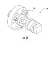
FIGS. 3A-3C , apin assembly 54 is illustrated. Thepin assembly 54 includes aninner pin portion 56 and anouter pin portion 58. The inner bore of the outer pin is eccentric to the outer diameter of the outer pin. This allows for the outer pin to be rotated and thus change the centerline location of the inner pin. Eccentric pins are often used in turbine systems to allow for precise external alignment capability of the inner casing relative to the rotor.Inner pin portion 56 includes an expandedledge 60 on the radialinnermost end 62 of theinner pin portion 56.Ledge 60 can have a generally square shape that interfaces with a complimentary female receiver defined by inner shell (shown inFIG. 2 ).Bolt section 64 extends fromledge 60 and can be generally cylindrical in shape.Bolt section 64 can include one ormore contact pads 70 which allow for deterministic loading withouter pin portion 58.Bolt section 64 includes asection 66 having smaller diameter to accommodatepin assembly 54 being located between two bolts as will be further described herein. Theoutermost end 67 ofinner pin portion 56 can define threads to receive aninner nut 68. -
Outer pin portion 58 includes an enlarged head 71 having abolt circle 72 with one or more circumferentially definedbolt openings 74. Bolt circle further defines anopening 80 thatoutermost end 67 ofinner pin portion 56 can extend through. The bolt openings can be configured to receive one ormore bolts 76 that react out pin rotation through friction which can set alignment of inner and outer turbine casings.Alignment portion 78 extends frombolt circle 72 and defines an opening (not shown) in communication withbolt circle opening 80 which can receive inner pin portion and also allow for outer pin rotations after assembly within the alignment requirements of the unit. Alignment portion includescontact pads 84 that allow deterministic loading with the inner and outer turbine casings and which are generally aligned withcontact pads 70 of inner pin portion. Alignment portion includes one ormore alignment scallops 82 which permitpin assembly 54 to be located between two bolts as will be further described herein.Alignment scallops 82 are defined, in part, byridge portions 85 that each have a width that is approximately the same as or less than the diameter ofsection 66 ofbolt section 64 to allow for outer pin rotations and subsequent inner pin eccentricity after assembly during unit alignment. In this manner,alignment portion 78 does not obstruct the bolts that secure the upper and lower outer casing casings. - When assembled,
inner pin portion 56 can interface with an inner casing section and be joined toouter pin portion 58 which contacts outer casing through the outer casing flange.Inner nut 68 can secureinner pin portion 56 toouter pin portion 58 and can be covered by abore cap 86 which is secured to boltcircle 72. - As illustrated in
FIGS. 4 and5 ,pin assembly 54 can be utilized for mounting and/or alignment of an inner turbine casing (not shown) through a horizontaljoint flange 52 ofouter turbine casing 14 without impactingouter casing bolt 50 spacing and/or leakage. For instance, as can be seen fromFIG. 5 , which represents a view in which the inner turbine casing and outer turbine casing are not shown, thesection 66 andridge portions 85 permit pin assembly to be located betweenbolts 50 which are utilized to secure the upper and lower outer casing casings. - One of ordinary skill in the art will readily appreciate that the structure previously described with respect to
FIGS. 1-5 provides a method for assembling aturbine 10. The method generally includes joining the inner casing and the outer casing together with a pin assembly as described herein. A first outer casing section and a second outer casing section are joined together with two bolts. The inner casing is surrounded with the outer casing. - Empirical testing and computer-generated models indicate that various embodiments of the present disclosure can one or more benefits over existing turbine casing assembly mechanisms and methods. The pin assemblies described herein can provide a convenient and reliable structure for ensuring the
inner casings 12 are concentrically attached to theouter casing 14 during assembly without impacting casing bolt spacing and/or leakage. - This written description uses examples to disclose the invention, including the best mode, and also to enable any person skilled in the art to practice the invention, including making and using any devices or systems and performing any incorporated methods. The patentable scope of the invention is defined by the claims, and may include other examples that occur to those skilled in the art. Such other and examples are intended to be within the scope of the claims if they include structural elements that do not differ from the literal language of the claims, or if they include equivalent structural elements with insubstantial differences from the literal languages of the claims.
Claims (13)
- A turbine casing assembly comprising:an inner casing (14);an outer casing(12) surrounding the inner casing (14), wherein the outer casing (12) comprises a first outer casing section (125) and a second outer casing (126) section that join together along a flange (52);two bolts (50) extending through the flange (52) and joining together the first outer casing section (125) and the second outer casing section (126); anda pin (54), the pin comprising a first segment (56) having a first diameter and a second segment (58) having a second diameter, wherein the first diameter is greater than the second diameter, the pin (54) extending through the inner casing (14) and the outer casing (12) and supporting the inner casing (14) relative to the outer casing (12), the pin (54) being located between the two bolts (50) along the axis of the flange (52).
- A turbine casing assembly as in claim 1, wherein the pin (54) further comprises an inner pin (56) and an outer pin (58), the inner pin (56) defining the first diameter and the second diameter, the outer pin (58) configured to house at least a portion of the inner pin (56).
- A turbine casing assembly as in claim 2, wherein the outer pin (58) is configured to surround a portion of the inner pin (56).
- A turbine casing assembly as in claim 1, wherein the second diameter is less than the distance between the two bolts (50).
- A turbine casing assembly as in claim 2, wherein the outer pin (58) can rotate in relation to the inner pin (56).
- A turbine casing assembly as in claim 2, wherein the inner pin (56) further comprises a contact pad (70) which contacts the outer pin (58).
- A turbine casing assembly as in claim 6, wherein the outer pin (58) further comprises a contact pad (84), the outer pin contact pad (84) being generally aligned with the inner pin contact pad (70), the outer pin contact pad (84) contacting the turbine casing (10).
- A turbine casing assembly as in claim 1, wherein the inner casing (14) comprises a first inner casing (145) and a second inner casing (146) that join together along a flange.
- A turbine comprising:the turbine casing assembly of any of claims 1 to 8, and wherein,the inner casing (14) carries nozzles (16,18) and shrouds, the shrouds surrounding tips of buckets (30) carried by a turbine rotor (20) within the inner casing (14).
- A method for assembling a turbine casing comprising:a. joining together an inner casing (14) and an outer casing (12) with a pin (54), the pin comprising a first segment (56) having a first diameter and a second segment (58) having a second diameter, wherein the first diameter is greater than the second diameter, the pin (54) extending through the inner casing (14) and the outer casing 12);b. joining together a first outer casing section (125) and a second outer casing section (126) with two bolts (50), the pin (54) being located between the two bolts (50); andc. surrounding the inner casing (14) with the outer casing (12).
- A method as in claim 10, wherein the pin (54) further comprises an inner pin (56) and an outer pin (58), the inner pin (56) defining the first diameter and the second diameter, the outer pin (58) configured to house at least a portion of the inner pin (56).
- A method as in claim 11, wherein the outer pin (58) is configured to surround a portion of the inner pin (58).
- A method as in any of claims 10 to 12, wherein the second diameter is less than the distance between the two bolts (50).
Applications Claiming Priority (1)
| Application Number | Priority Date | Filing Date | Title |
|---|---|---|---|
| US13/226,823 US8992167B2 (en) | 2011-09-07 | 2011-09-07 | Turbine casing assembly mounting pin |
Publications (2)
| Publication Number | Publication Date |
|---|---|
| EP2568125A2 true EP2568125A2 (en) | 2013-03-13 |
| EP2568125A3 EP2568125A3 (en) | 2017-09-20 |
Family
ID=46758644
Family Applications (1)
| Application Number | Title | Priority Date | Filing Date |
|---|---|---|---|
| EP12182829.7A Withdrawn EP2568125A3 (en) | 2011-09-07 | 2012-09-03 | Turbine casing assembly mounting pin |
Country Status (3)
| Country | Link |
|---|---|
| US (1) | US8992167B2 (en) |
| EP (1) | EP2568125A3 (en) |
| CN (1) | CN102996189B (en) |
Cited By (1)
| Publication number | Priority date | Publication date | Assignee | Title |
|---|---|---|---|---|
| EP3260669A1 (en) * | 2016-06-23 | 2017-12-27 | Rolls-Royce Deutschland Ltd & Co KG | Housing for a rotor of an engine |
Families Citing this family (4)
| Publication number | Priority date | Publication date | Assignee | Title |
|---|---|---|---|---|
| US9273569B2 (en) * | 2013-01-08 | 2016-03-01 | General Electric Company | Gas turbine half-casing lifting and shipping fixture |
| EP2952688A1 (en) * | 2014-06-02 | 2015-12-09 | Siemens Aktiengesellschaft | Method for assembling a stator stage of a gas turbine engine |
| US20190284947A1 (en) * | 2018-03-14 | 2019-09-19 | General Electric Company | Cmc shroud segment with interlocking mechanical joints and fabrication |
| DE102023128305A1 (en) * | 2023-10-16 | 2025-04-17 | MPS-Consulting GmbH | Stator for a gas turbine |
Family Cites Families (20)
| Publication number | Priority date | Publication date | Assignee | Title |
|---|---|---|---|---|
| US3083863A (en) * | 1959-01-29 | 1963-04-02 | Gen Electric | Flange construction |
| US3628884A (en) * | 1970-06-26 | 1971-12-21 | Westinghouse Electric Corp | Method and apparatus for supporting an inner casing structure |
| BE786674A (en) * | 1971-07-26 | 1973-01-25 | Westinghouse Electric Corp | MULTI-ENCLOSURE TURBINE |
| CH589799A5 (en) * | 1975-07-04 | 1977-07-15 | Bbc Brown Boveri & Cie | |
| US4585390A (en) * | 1984-06-04 | 1986-04-29 | General Electric Company | Vane retaining means |
| US4832574A (en) * | 1988-02-12 | 1989-05-23 | United Technologies Corporation | Turbine disk securing and removal apparatus |
| US5271714A (en) | 1992-07-09 | 1993-12-21 | General Electric Company | Turbine nozzle support arrangement |
| US6224332B1 (en) | 1999-05-14 | 2001-05-01 | General Electric Co. | Apparatus and methods for installing, removing and adjusting an inner turbine shell section relative to an outer turbine shell section |
| KR20010007065A (en) * | 1999-05-18 | 2001-01-26 | 제이 엘. 차스킨 | Inner shell radial pin geometry and mounting arrangement |
| US6402468B1 (en) | 2001-06-18 | 2002-06-11 | General Electric Company | Method and apparatus for axially aligning inner and outer turbine shell components |
| US6860716B2 (en) * | 2003-05-29 | 2005-03-01 | General Electric Company | Turbomachine frame structure |
| US6951112B2 (en) * | 2004-02-10 | 2005-10-04 | General Electric Company | Methods and apparatus for assembling gas turbine engines |
| JP4801373B2 (en) * | 2005-05-16 | 2011-10-26 | 三菱重工業株式会社 | Turbine cabin structure |
| US7617602B2 (en) | 2005-08-18 | 2009-11-17 | General Electric Company | Method of servicing a turbine |
| US7520721B2 (en) | 2006-09-19 | 2009-04-21 | General Electric Company | System and method for aligning and sealing a turbine shell assembly |
| US8182207B2 (en) | 2008-03-17 | 2012-05-22 | General Electric Company | Inner turbine shell support configuration and methods |
| US8099962B2 (en) * | 2008-11-28 | 2012-01-24 | Pratt & Whitney Canada Corp. | Mid turbine frame system and radial locator for radially centering a bearing for gas turbine engine |
| US8231338B2 (en) * | 2009-05-05 | 2012-07-31 | General Electric Company | Turbine shell with pin support |
| EP2473712B1 (en) * | 2009-09-02 | 2013-07-03 | Siemens Aktiengesellschaft | A mounting apparatus |
| US8870529B2 (en) * | 2011-08-12 | 2014-10-28 | General Electric Company | Methods and apparatus to facilitate turbine casing assembly |
-
2011
- 2011-09-07 US US13/226,823 patent/US8992167B2/en active Active
-
2012
- 2012-09-03 EP EP12182829.7A patent/EP2568125A3/en not_active Withdrawn
- 2012-09-07 CN CN201210331451.4A patent/CN102996189B/en active Active
Non-Patent Citations (1)
| Title |
|---|
| None |
Cited By (1)
| Publication number | Priority date | Publication date | Assignee | Title |
|---|---|---|---|---|
| EP3260669A1 (en) * | 2016-06-23 | 2017-12-27 | Rolls-Royce Deutschland Ltd & Co KG | Housing for a rotor of an engine |
Also Published As
| Publication number | Publication date |
|---|---|
| US20130058779A1 (en) | 2013-03-07 |
| EP2568125A3 (en) | 2017-09-20 |
| CN102996189A (en) | 2013-03-27 |
| CN102996189B (en) | 2016-03-16 |
| US8992167B2 (en) | 2015-03-31 |
Similar Documents
| Publication | Publication Date | Title |
|---|---|---|
| US10221711B2 (en) | Integrated strut and vane arrangements | |
| EP2900973B1 (en) | Mid-turbine frame with fairing attachment | |
| US8651809B2 (en) | Apparatus and method for aligning a turbine casing | |
| US8727719B2 (en) | Annular flange for fastening a rotor or stator element in a turbomachine | |
| JP6141871B2 (en) | High temperature gas expansion device inlet casing assembly and method | |
| US9834312B2 (en) | Method for holding an adapter piece on a tubular housing of a turbo engine, and corresponding adapter piece and holding system | |
| EP2568125A2 (en) | Turbine casing assembly mounting pin | |
| US20170009989A1 (en) | Gas turbine combustion chamber with integrated turbine inlet guide vane ring as well as method for manufacturing the same | |
| US9982564B2 (en) | Turbine frame assembly and method of designing turbine frame assembly | |
| US20170130608A1 (en) | Turbine assembly with detachable struts | |
| US9255523B2 (en) | Fastening element and de-icing device of an aircraft gas-turbine engine | |
| US8864459B2 (en) | Turbine casing assembly mounting pin | |
| US20070031245A1 (en) | Thermally compliant C-clip | |
| US8967978B2 (en) | Axial retention for fasteners in fan joint | |
| US20160146051A1 (en) | Turbine engine casing having a cut-out flange | |
| JP6249499B2 (en) | Multi-piece frame for turbine exhaust case | |
| EP3797211B1 (en) | Turbine exhaust crack mitigation using partial collars | |
| CA2858041C (en) | Combustor floating collar assembly | |
| JP7076943B2 (en) | Combustor cap module and holding system for it | |
| EP3486435B1 (en) | Fuse joint with fenestrated fuse pin | |
| JP2014095380A (en) | System for assembling and disassembling turbine section of gas turbine | |
| CN114080491A (en) | Output bearing support for a turbomachine | |
| US20170241277A1 (en) | Movable interface for gas turbine engine | |
| JP6736301B2 (en) | Combustor rear mounting assembly | |
| CN107366559B (en) | Systems and methods for gas turbine engines |
Legal Events
| Date | Code | Title | Description |
|---|---|---|---|
| PUAI | Public reference made under article 153(3) epc to a published international application that has entered the european phase |
Free format text: ORIGINAL CODE: 0009012 |
|
| AK | Designated contracting states |
Kind code of ref document: A2 Designated state(s): AL AT BE BG CH CY CZ DE DK EE ES FI FR GB GR HR HU IE IS IT LI LT LU LV MC MK MT NL NO PL PT RO RS SE SI SK SM TR |
|
| AX | Request for extension of the european patent |
Extension state: BA ME |
|
| PUAL | Search report despatched |
Free format text: ORIGINAL CODE: 0009013 |
|
| AK | Designated contracting states |
Kind code of ref document: A3 Designated state(s): AL AT BE BG CH CY CZ DE DK EE ES FI FR GB GR HR HU IE IS IT LI LT LU LV MC MK MT NL NO PL PT RO RS SE SI SK SM TR |
|
| AX | Request for extension of the european patent |
Extension state: BA ME |
|
| RIC1 | Information provided on ipc code assigned before grant |
Ipc: F01D 25/24 20060101AFI20170811BHEP Ipc: F01D 25/26 20060101ALI20170811BHEP |
|
| 17P | Request for examination filed |
Effective date: 20180320 |
|
| RBV | Designated contracting states (corrected) |
Designated state(s): AL AT BE BG CH CY CZ DE DK EE ES FI FR GB GR HR HU IE IS IT LI LT LU LV MC MK MT NL NO PL PT RO RS SE SI SK SM TR |
|
| 17Q | First examination report despatched |
Effective date: 20190606 |
|
| STAA | Information on the status of an ep patent application or granted ep patent |
Free format text: STATUS: THE APPLICATION IS DEEMED TO BE WITHDRAWN |
|
| 18D | Application deemed to be withdrawn |
Effective date: 20191217 |