EP2567873A2 - Systems and methods for improved aircraft braking - Google Patents
Systems and methods for improved aircraft braking Download PDFInfo
- Publication number
- EP2567873A2 EP2567873A2 EP12171669A EP12171669A EP2567873A2 EP 2567873 A2 EP2567873 A2 EP 2567873A2 EP 12171669 A EP12171669 A EP 12171669A EP 12171669 A EP12171669 A EP 12171669A EP 2567873 A2 EP2567873 A2 EP 2567873A2
- Authority
- EP
- European Patent Office
- Prior art keywords
- wheel
- brake controller
- velocity
- aircraft
- compensation factor
- Prior art date
- Legal status (The legal status is an assumption and is not a legal conclusion. Google has not performed a legal analysis and makes no representation as to the accuracy of the status listed.)
- Granted
Links
Images


Classifications
-
- B—PERFORMING OPERATIONS; TRANSPORTING
- B60—VEHICLES IN GENERAL
- B60T—VEHICLE BRAKE CONTROL SYSTEMS OR PARTS THEREOF; BRAKE CONTROL SYSTEMS OR PARTS THEREOF, IN GENERAL; ARRANGEMENT OF BRAKING ELEMENTS ON VEHICLES IN GENERAL; PORTABLE DEVICES FOR PREVENTING UNWANTED MOVEMENT OF VEHICLES; VEHICLE MODIFICATIONS TO FACILITATE COOLING OF BRAKES
- B60T8/00—Arrangements for adjusting wheel-braking force to meet varying vehicular or ground-surface conditions, e.g. limiting or varying distribution of braking force
- B60T8/17—Using electrical or electronic regulation means to control braking
- B60T8/1701—Braking or traction control means specially adapted for particular types of vehicles
- B60T8/1703—Braking or traction control means specially adapted for particular types of vehicles for aircrafts
-
- B—PERFORMING OPERATIONS; TRANSPORTING
- B60—VEHICLES IN GENERAL
- B60T—VEHICLE BRAKE CONTROL SYSTEMS OR PARTS THEREOF; BRAKE CONTROL SYSTEMS OR PARTS THEREOF, IN GENERAL; ARRANGEMENT OF BRAKING ELEMENTS ON VEHICLES IN GENERAL; PORTABLE DEVICES FOR PREVENTING UNWANTED MOVEMENT OF VEHICLES; VEHICLE MODIFICATIONS TO FACILITATE COOLING OF BRAKES
- B60T8/00—Arrangements for adjusting wheel-braking force to meet varying vehicular or ground-surface conditions, e.g. limiting or varying distribution of braking force
- B60T8/17—Using electrical or electronic regulation means to control braking
- B60T8/172—Determining control parameters used in the regulation, e.g. by calculations involving measured or detected parameters
-
- B—PERFORMING OPERATIONS; TRANSPORTING
- B60—VEHICLES IN GENERAL
- B60T—VEHICLE BRAKE CONTROL SYSTEMS OR PARTS THEREOF; BRAKE CONTROL SYSTEMS OR PARTS THEREOF, IN GENERAL; ARRANGEMENT OF BRAKING ELEMENTS ON VEHICLES IN GENERAL; PORTABLE DEVICES FOR PREVENTING UNWANTED MOVEMENT OF VEHICLES; VEHICLE MODIFICATIONS TO FACILITATE COOLING OF BRAKES
- B60T2201/00—Particular use of vehicle brake systems; Special systems using also the brakes; Special software modules within the brake system controller
- B60T2201/16—Curve braking control, e.g. turn control within ABS control algorithm
-
- B—PERFORMING OPERATIONS; TRANSPORTING
- B60—VEHICLES IN GENERAL
- B60T—VEHICLE BRAKE CONTROL SYSTEMS OR PARTS THEREOF; BRAKE CONTROL SYSTEMS OR PARTS THEREOF, IN GENERAL; ARRANGEMENT OF BRAKING ELEMENTS ON VEHICLES IN GENERAL; PORTABLE DEVICES FOR PREVENTING UNWANTED MOVEMENT OF VEHICLES; VEHICLE MODIFICATIONS TO FACILITATE COOLING OF BRAKES
- B60T2210/00—Detection or estimation of road or environment conditions; Detection or estimation of road shapes
- B60T2210/20—Road shapes
- B60T2210/24—Curve radius
-
- B—PERFORMING OPERATIONS; TRANSPORTING
- B60—VEHICLES IN GENERAL
- B60T—VEHICLE BRAKE CONTROL SYSTEMS OR PARTS THEREOF; BRAKE CONTROL SYSTEMS OR PARTS THEREOF, IN GENERAL; ARRANGEMENT OF BRAKING ELEMENTS ON VEHICLES IN GENERAL; PORTABLE DEVICES FOR PREVENTING UNWANTED MOVEMENT OF VEHICLES; VEHICLE MODIFICATIONS TO FACILITATE COOLING OF BRAKES
- B60T2250/00—Monitoring, detecting, estimating vehicle conditions
- B60T2250/04—Vehicle reference speed; Vehicle body speed
Definitions
- the present disclosure is related to systems and methods for aircraft braking for use in, for example, an aircraft.
- Aircraft braking systems often include locked wheel protection. Locked wheel protection prevents wheel lock in circumstances where tire skidding would have otherwise occurred, for example, during landing on a runway with a low coefficient of friction, such as an icy runway. Tire skidding occurs when a tire ceases or substantially ceases to rotate relative to a landing surface (e.g., runway), resulting in sliding of the tire. Tire skidding may cause an aircraft to lose directional control, which is typically hazardous. Aircraft may be steered by selectively applying braking to one or more wheels. For example, an aircraft may be steered to the left by selectively applying the left side brakes, causing the aircraft to pivot about the left side wheels.
- a locked wheel protection system may interpret such steering methods as an imminent tire skid, and thus apply locked wheel protecting techniques.
- the locked wheel protecting techniques typically result in unpredictable aircraft movements, and thus, may be disconcerting to the pilot.
- a locked wheel protecting technique may comprise releasing all braking pressure. Such a locked wheel protecting technique may disrupt steering. Thus, improved braking systems are desirable.
- a method comprising determining, at a brake controller, an aircraft reference speed for an aircraft having a first wheel and a second wheel; identifying, at the brake controller, a state comprising the first wheel having a different rotational velocity than the second wheel, wherein the difference in rotational velocity sums to about zero; calculating, at the brake controller, a compensation factor for at least one of the first wheel and the second wheel; and adjusting, at the brake controller, a locked wheel trigger velocity in accordance with the compensation factor.
- the method may further comprise deriving a turning radius of the aircraft.
- the calculating may occur in response to determining that the turning radius is below a threshold.
- the aircraft reference speed may remain constant.
- the adjusting may occur in response to the expiration of a preset amount of time.
- the compensation factor may be expressed as a percentage of the locked wheel trigger velocity.
- a system comprising a brake controller having locked wheel protecting functionality comprising a locked wheel trigger velocity, a first wheel velocity sensor and a second wheel velocity sensor, wherein the first wheel velocity and the second wheel velocity are available to the brake controller, wherein the brake controller receives the identifies a state comprising the first wheel velocity is different from the second wheel velocity, wherein the difference in rotational velocity sums to about zero, wherein the brake controller calculates a compensation factor for at least one of the first wheel and the second wheel, and wherein the brake controller adjusts a locked wheel trigger velocity in accordance with the compensation factor.
- a computer readable medium bears instructions for braking, the instructions, when executed by a brake controller, cause the brake controller to perform operations comprising determining, at the brake controller, an aircraft reference speed for an aircraft having a first wheel and a second wheel; identifying, at the brake controller, a state comprising the first wheel having a different rotational velocity than the second wheel, wherein the difference in rotational velocity sums to about zero; calculating, at the brake controller, a compensation factor for at least one of the first wheel and the second wheel; and adjusting, at the brake controller, a locked wheel trigger velocity in accordance with the compensation factor.
- any reference to singular includes plural embodiments, and any reference to more than one component or step may include a singular embodiment or step.
- any reference to attached, fixed, connected or the like may include permanent, removable, temporary, partial, full and/or any other possible attachment option.
- any reference to without contact (or similar phrases) may also include reduced contact or minimal contact.
- Systems and methods disclosed herein may be useful for braking systems. Although the embodiments herein are described with reference to braking systems used in connection with aircraft, such embodiments are provided for example only as it is contemplated that the disclosures herein have applicability to other vehicles, such as for example, automobiles.
- Aircraft braking systems typically receive braking commands (e.g. from a pilot or copilot) via pedals that are conventionally operated with a foot or feet.
- the amount of pedal deflection typically corresponds to the amount of braking force desired or, in some aircraft, pedal deflection varies in accordance with desired deceleration.
- the pilot and copilot each have a left pedal and a right pedal.
- the left pedal controls the brakes on the wheels on the left side of the aircraft and the right pedal controls the brakes on the wheels on the right side of the aircraft. It should be noted that there may be one or more wheels coupled to one or more brakes on each the left side and the right side of the aircraft.
- a pilot or copilot may selectively apply braking to one side of the aircraft.
- increased braking on the left wheels will effect a left-hand turn of the aircraft.
- the left wheels will slow down and the right wheels will speed up, but the aircraft reference speed may remain constant in certain circumstances.
- the aircraft reference speed may comprise the overall velocity of the aircraft.
- the aircraft reference speed may be the speed of the center of the aircraft.
- Aircraft may comprise one or more types of aircraft wheel and brake assemblies.
- an aircraft wheel and brake assembly may comprise a non-rotatable wheel support, a wheel mounted to the wheel support for rotation, and a brake disk stack.
- the brake disk stack may have front and rear axial ends and alternating rotor and stator disks mounted with respect to the wheel support and wheel for relative axial movement.
- Each rotor disk may be coupled to the wheel for rotation therewith and each stator disk is coupled to the wheel support against rotation.
- a back plate may be located at the rear end of the disk pack and a brake head may be located at the front end.
- the brake head may house one or more actuator rams that extend to compress the brake disk stack against the back plate. Torque is taken out by the stator disks through a static torque tube or the like.
- the actuator rams may be electrically operated actuator rams or hydraulically operated actuator rams, although some brakes may use pneumatically operated actuator rams.
- the actuator ram may be coupled to a power source via a brake servo valve ("BSV") and a shutoff valve (“SOV").
- BSV brake servo valve
- SOV shutoff valve
- the SOV effectively functions as a shutoff valve, wherein in a first position (e.g., an armed position) fluid pressure is permitted to pass through the valve. While in a second position (e.g., a disarmed position), fluid pressure is prevented from passing through the valve. During normal braking, the SOV is in the armed position, thereby permitting the flow of fluid pressure.
- the BSV based on braking commands from the pilot (often via an electronic controller that may implement, for example, locked wheel protection logic), controls the amount of fluid pressure provided to the actuator ram, and thus, the braking force applied to the wheel.
- the SOV is set in the disarmed position, thereby removing fluid pressure from the BSV. Since the BSV does not receive fluid pressure, it cannot provide fluid pressure to the actuator ram, and thus, braking cannot be effected.
- a brake controller is coupled to one or more electromechanical actuator controllers ("EMAC”) for brakes which drives one or more electromechanical brake actuators.
- EMAC electromechanical actuator controller
- an aircraft may have one or more brake pedals that receive braking commands. Braking commands may be received at a brake controller.
- a brake controller may comprise a module that comprises a processor, a non-transitory, tangible memory, and braking logic. The brake controller may process the braking commands received from the brake pedal using braking logic and provide commands to other components, such as an EMAC or a BSV.
- Braking logic may include locked wheel protection functionality. Locked wheel protection functionality may have the capability to determine when one or more wheels may enter a skid and then cause locked wheel protecting techniques to be applied.
- a skid may be identified by, for example, detecting one wheel slowing to below a certain proportion of the aircraft reference speed.
- an aircraft at 100 knots having a wheel that is rotating at 50 knots may indicate that the wheel is skidding.
- one locked wheel protecting technique comprises partially releasing pressure on the brake so that the wheel may regain traction with the landing surface.
- one locked wheel protecting technique is to release all brake pressure.
- Locked wheel protecting functionality may include a trigger velocity.
- Trigger velocity is a velocity below which the brake controller triggers locked wheel protecting techniques.
- Trigger velocity may comprise a particular speed or a proportion of the aircraft reference speed. For example, about 10 knots may comprise a trigger velocity or about 50% of aircraft reference speed may comprise a drop trigger out velocity.
- a trigger velocity may comprise a range. For example, if a trigger velocity may include 50% of aircraft reference speed and 150% of aircraft reference speed.
- locked wheel protecting techniques e.g., full or partial release of brake pressure
- the aircraft reference speed may exceed the trigger velocity yet, in certain circumstances, locked wheel protection functionality is undesirable.
- an aircraft with a trigger velocity of 50% of aircraft reference speed may enter a left turn at 20 knots.
- the left wheel may slow to 10 knots, thus triggering the brake controller to employ locked wheel protecting techniques.
- the left wheel will have braking pressure released, and the aircraft will handle in a manner inconsistent with pilot/copilot commands.
- the trigger velocity has an upper limit, such as 150% of aircraft reference speed
- the outer wheel in a turn may exceed the trigger velocity.
- the range of velocities where locked wheel protecting techniques are not employed may be referred to as the trigger velocity range.
- a left wheel and right wheel may also be referred to as an inboard wheel and an outboard wheel, the inboard wheel being closer to the axis of the turning circle than the outboard wheel.
- the left wheel and right wheel may also be referred to as a first wheel and a second wheel.
- systems and methods in accordance with various embodiments detect and/or identify a turning event (i.e., steering) and may determine a compensation factor.
- a compensation factor may comprise an adjustment value for use in adjusting the trigger velocity.
- a compensation factor may be a particular number or a percentage of aircraft reference speed. In this manner, the trigger velocity for a particular wheel may be raised or lowered such that locked wheel protecting techniques are not employed.
- Determine aircraft reference speed 102 comprises determining the overall speed of the aircraft. Aircraft reference speed may be determined using any known method or methods that are developed herein. Aircraft reference speed may be determined by averaging wheel speed sensors, or through other means. Determine aircraft reference speed 102 may be performed by the brake controller or the aircraft reference speed may be received at the brake controller.
- Identify steering 104 may comprise identifying that steering is occurring. Identify steering 104 may be performed by the brake controller. As discussed above, selective application of brakes may effect steering. Thus, the left wheels and right wheels may rotate at different speeds during steering. Moreover, during steering, the left wheels and right wheels change rotational velocities at the same or substantially the same rate. For example, if the left wheels slow by 2 knots, the right wheels will increase by 2 knots. By identifying that the left wheels and the right wheels differ by the same or substantially same amount, it may be determined that steering is occurring. Commanded deceleration is a braking scheme wherein brake pedal deflection is correlated with a particular commanded deceleration.
- Commanded pressure is a braking scheme wherein brake pedal deflection is correlated with a particular commanded pressure to be applied at the brake.
- the commanded deceleration may be subtracted from the current wheel speed to yield the future wheel speed.
- various methods may be used to identify steering. For example, when the difference in pressure between two wheels exceeds a particular threshold, steering may be identified, taking into account potential pressure differences due to other factors such as brake friction difference or cross winds.
- calculate compensation factor 106 may occur.
- Calculate compensation factor 106 may comprise the calculation of a compensation factor to temporarily change the trigger velocity to compensate for the steering.
- a compensation factor may be determined using any suitable method. As should be appreciated, there are a number of ways to calculate a compensation factor, depending on aircraft geometry, configuration, turning force, and other factors.
- the compensation factor may be set to adjust the trigger velocity such that locked wheel protecting techniques would not be used so long as a steering event is occurring. For example, an aircraft with a trigger velocity range of 50% of aircraft reference speed and 150% of aircraft reference speed may enter a left turn at 20 knots. The left wheel may slow to 10 knots.
- a compensation factor may be calculated to prevent the locked wheel protecting techniques from being employed on the left wheel.
- a compensation factor may comprise 1 knot and/or the compensation factor may comprise 10% of aircraft reference speed. Accordingly, the left wheel will be remain within trigger velocity range during steering and locked wheel protecting techniques will be avoided.
- V wheel is the speed of the wheel being observed
- V ref is the aircraft reference speed
- LW_DELTA is the trigger velocity
- a compensation factor may comprise a range of compensation factors.
- the compensation factor (CF) may be: CF ⁇ 0.015 ⁇ aircraft reference speed 2 - 0.85 aircraft reference speed + 14
- Calculate compensation factor 106 may be repeated during the steering event to ensure that an appropriate compensation factor is being used.
- Adjust locked wheel trigger velocity 108 comprises adjusting the locked wheel trigger velocity in accordance with the compensation factor.
- the adjustment may be in the form of a change in the proportion of aircraft reference speed or a change in a particular aircraft reference speed.
- Adjust locked wheel trigger velocity 108 may be repeated during the steering event to ensure that the compensation factor is being implemented.
- Adjust locked wheel trigger velocity 108 may include adjusting the inner wheel to account for its decrease in rotational velocity and adjusting the outer wheel to account for its increase in rotational velocity.
- the compensation factor will be the same for both wheels, only opposite in sign. Thus, a decrease of 3 knots on a left wheel will coincide with an increase of 3 knots on the right wheel.
- the turning radius may be used to identify steering and/or in calculating the compensation factor.
- turning radii may be associated with an appropriate compensation factor.
- FIG. 4 method 400 is illustrated.
- Method 400 contains steps described above with reference to FIG. 1 , but also includes derive turning radius 402.
- Derive turning radius 402 is illustrated.
- Derive turning radius 402 may comprise any method for determining a turning radius. Turning radius may be understood with reference to FIG. 2 , wherein a turning radius example 200 is shown.
- Line 202 represents the length of an object making a turn.
- Radius 204 and Radius 212 illustrate multiple radii drawn from the terminals of line 202.
- ⁇ 206 represents the steering angle.
- Line 202 and radii 204 and 212 form a triangle having angles ⁇ 206 and angles 208 and 210, which are identical in value. It should be understood, of course, that the sum of the three angles of a triangle equal 180°.
- 180 ⁇ - 2(x), where x equals the value of angle 208 and angle 210.
- Aircraft length 302 represents the length of the aircraft as determined by the distance from the front wheels to its intersection with a line connecting the right wheels and the left wheels.
- Radius 304 and Radius 312 illustrate multiple radii drawn from the terminals of aircraft length 302.
- ⁇ 306 represents the steering angle.
- radii 304 and 312 may be determined using the law of sines, per the above.
- derive turning radius 402 may comprise the method of deriving a turning radius as described above with respect to the FIG. 3 .
- calculate compensation factor 106 includes calculating a compensation factor based upon the turning radius. Compensation factors may be predetermined and associated with various turning radii. In various embodiments, calculate compensation factor 106 includes logic to calculate a compensation factor in response to a turning radius. Typically, the smaller the turning radius, the larger the compensation factor will be because at least one wheel will slow more significantly than during a turn with a longer turning radius.
- the calculation of a compensation factor may occur only when aircraft reference speed is within a particular range. At lower speeds, aircraft reference speed may not be reliably calculated.
- various locked wheel protection functionality logic has a dropout velocity, below which locked wheel protecting techniques will not occur. Thus, a compensation factor would be unnecessary. At higher speeds, a wheel may not slow to below the trigger velocity and/or a turn may be potentially unsafe due to the higher speed. Thus, it may be desirable to use an upper limit beyond which a compensation factor is not used.
- compensation factors may be applied at speeds of between about 5 knots to about 50 knots and more preferably between about 10 knots and about 30 knots.
- FIG. 5 illustrates compensation factor curve 500.
- a simulation is run to plot compensation factors by aircraft reference speed.
- the y axis shows the compensation factor in knots and the x axis shows aircraft reference speed in knots.
- Curve 502 represents the compensation factor relationship: CF ⁇ 0.015 ⁇ aircraft reference speed 2 - 0.85 aircraft reference speed + 14
- non-transitory computer-readable medium should be construed to exclude only those types of transitory computer-readable media which were found in In re Nuijten, 500 F.3d 1346 (Fed. Cir. 2007) to fall outside the scope of patentable subject matter under 35 U.S.C. ⁇ 101, so long as and to the extent In re Nuijten remains binding authority in the U.S. federal courts and is not overruled by a future case or statute. Stated another way, the term “computer-readable medium” should be construed in a manner that is as broad as legally permissible.
- references to "one embodiment”, “an embodiment”, “an example embodiment”, etc. indicate that the embodiment described may include a particular feature, structure, or characteristic, but every embodiment may not necessarily include the particular feature, structure, or characteristic. Moreover, such phrases are not necessarily referring to the same embodiment. Further, when a particular feature, structure, or characteristic is described in connection with an embodiment, it is submitted that it is within the knowledge of one skilled in the art to effect such feature, structure, or characteristic in connection with other embodiments whether or not explicitly described. After reading the description, it will be apparent to one skilled in the relevant art(s) how to implement the disclosure in alternative embodiments.
Landscapes
- Engineering & Computer Science (AREA)
- Transportation (AREA)
- Mechanical Engineering (AREA)
- Aviation & Aerospace Engineering (AREA)
- Regulating Braking Force (AREA)
Abstract
Description
- The present disclosure is related to systems and methods for aircraft braking for use in, for example, an aircraft.
- Aircraft braking systems often include locked wheel protection. Locked wheel protection prevents wheel lock in circumstances where tire skidding would have otherwise occurred, for example, during landing on a runway with a low coefficient of friction, such as an icy runway. Tire skidding occurs when a tire ceases or substantially ceases to rotate relative to a landing surface (e.g., runway), resulting in sliding of the tire. Tire skidding may cause an aircraft to lose directional control, which is typically hazardous. Aircraft may be steered by selectively applying braking to one or more wheels. For example, an aircraft may be steered to the left by selectively applying the left side brakes, causing the aircraft to pivot about the left side wheels. In certain low speed applications, a locked wheel protection system may interpret such steering methods as an imminent tire skid, and thus apply locked wheel protecting techniques. However, in these applications, the locked wheel protecting techniques typically result in unpredictable aircraft movements, and thus, may be disconcerting to the pilot. For example, a locked wheel protecting technique may comprise releasing all braking pressure. Such a locked wheel protecting technique may disrupt steering. Thus, improved braking systems are desirable.
- Systems and methods disclosed herein may be useful in braking systems. In this regard, in various embodiments, a method is provided comprising determining, at a brake controller, an aircraft reference speed for an aircraft having a first wheel and a second wheel; identifying, at the brake controller, a state comprising the first wheel having a different rotational velocity than the second wheel, wherein the difference in rotational velocity sums to about zero; calculating, at the brake controller, a compensation factor for at least one of the first wheel and the second wheel; and adjusting, at the brake controller, a locked wheel trigger velocity in accordance with the compensation factor.
- The method may further comprise deriving a turning radius of the aircraft. The calculating may occur in response to determining that the turning radius is below a threshold. The aircraft reference speed may remain constant. The adjusting may occur in response to the expiration of a preset amount of time. The compensation factor may be expressed as a percentage of the locked wheel trigger velocity. The compensation factor may be calculated using the formula:

- In various embodiments, a system is provided comprising a brake controller having locked wheel protecting functionality comprising a locked wheel trigger velocity, a first wheel velocity sensor and a second wheel velocity sensor, wherein the first wheel velocity and the second wheel velocity are available to the brake controller, wherein the brake controller receives the identifies a state comprising the first wheel velocity is different from the second wheel velocity, wherein the difference in rotational velocity sums to about zero, wherein the brake controller calculates a compensation factor for at least one of the first wheel and the second wheel, and wherein the brake controller adjusts a locked wheel trigger velocity in accordance with the compensation factor.
- In further embodiments, a computer readable medium is provided wherein the computer readable medium bears instructions for braking, the instructions, when executed by a brake controller, cause the brake controller to perform operations comprising determining, at the brake controller, an aircraft reference speed for an aircraft having a first wheel and a second wheel; identifying, at the brake controller, a state comprising the first wheel having a different rotational velocity than the second wheel, wherein the difference in rotational velocity sums to about zero; calculating, at the brake controller, a compensation factor for at least one of the first wheel and the second wheel; and adjusting, at the brake controller, a locked wheel trigger velocity in accordance with the compensation factor.
- Below is a summary of the drawing figures, wherein like numerals denote like elements and wherein:
-
FIG. 1 illustrates a method in accordance with various embodiments; -
FIG. 2 illustrates an example of turning radius calculation; -
FIG. 3 illustrates an example of turning radius calculation in the aircraft context; -
FIG. 4 illustrates a further method in accordance with various embodiments; and -
FIG. 5 illustrates an exemplary relationship in accordance with various embodiments. - The detailed description of exemplary embodiments herein makes reference to the accompanying drawings, which show exemplary embodiments by way of illustration and its best mode. While these exemplary embodiments are described in sufficient detail to enable those skilled in the art to practice the inventions, it should be understood that other embodiments may be realized and that logical, chemical and mechanical changes may be made without departing from the spirit and scope of the inventions. Thus, the detailed description herein is presented for purposes of illustration only and not of limitation. For example, the steps recited in any of the method or process descriptions may be executed in any order and are not necessarily limited to the order presented. Moreover, many of the functions or steps may be outsourced to or performed by one or more third parties. Furthermore, any reference to singular includes plural embodiments, and any reference to more than one component or step may include a singular embodiment or step. Also, any reference to attached, fixed, connected or the like may include permanent, removable, temporary, partial, full and/or any other possible attachment option. Additionally, any reference to without contact (or similar phrases) may also include reduced contact or minimal contact.
- Systems and methods disclosed herein may be useful for braking systems. Although the embodiments herein are described with reference to braking systems used in connection with aircraft, such embodiments are provided for example only as it is contemplated that the disclosures herein have applicability to other vehicles, such as for example, automobiles.
- Aircraft braking systems typically receive braking commands (e.g. from a pilot or copilot) via pedals that are conventionally operated with a foot or feet. The amount of pedal deflection typically corresponds to the amount of braking force desired or, in some aircraft, pedal deflection varies in accordance with desired deceleration. In a common aircraft configuration, the pilot and copilot each have a left pedal and a right pedal. The left pedal controls the brakes on the wheels on the left side of the aircraft and the right pedal controls the brakes on the wheels on the right side of the aircraft. It should be noted that there may be one or more wheels coupled to one or more brakes on each the left side and the right side of the aircraft. To effect steering, a pilot or copilot may selectively apply braking to one side of the aircraft. Thus, increased braking on the left wheels will effect a left-hand turn of the aircraft. As the turn occurs, the left wheels will slow down and the right wheels will speed up, but the aircraft reference speed may remain constant in certain circumstances. The aircraft reference speed may comprise the overall velocity of the aircraft. For example, the aircraft reference speed may be the speed of the center of the aircraft.
- Aircraft may comprise one or more types of aircraft wheel and brake assemblies. For example, an aircraft wheel and brake assembly may comprise a non-rotatable wheel support, a wheel mounted to the wheel support for rotation, and a brake disk stack. The brake disk stack may have front and rear axial ends and alternating rotor and stator disks mounted with respect to the wheel support and wheel for relative axial movement. Each rotor disk may be coupled to the wheel for rotation therewith and each stator disk is coupled to the wheel support against rotation. A back plate may be located at the rear end of the disk pack and a brake head may be located at the front end. The brake head may house one or more actuator rams that extend to compress the brake disk stack against the back plate. Torque is taken out by the stator disks through a static torque tube or the like.
- The actuator rams may be electrically operated actuator rams or hydraulically operated actuator rams, although some brakes may use pneumatically operated actuator rams. In brake systems that employ fluid powered (hydraulic or pneumatic power) actuator rams, the actuator ram may be coupled to a power source via a brake servo valve ("BSV") and a shutoff valve ("SOV"). The SOV effectively functions as a shutoff valve, wherein in a first position (e.g., an armed position) fluid pressure is permitted to pass through the valve. While in a second position (e.g., a disarmed position), fluid pressure is prevented from passing through the valve. During normal braking, the SOV is in the armed position, thereby permitting the flow of fluid pressure. The BSV, based on braking commands from the pilot (often via an electronic controller that may implement, for example, locked wheel protection logic), controls the amount of fluid pressure provided to the actuator ram, and thus, the braking force applied to the wheel. To prevent unintentional braking (e.g., due to a faulty servo valve) at various times, the SOV is set in the disarmed position, thereby removing fluid pressure from the BSV. Since the BSV does not receive fluid pressure, it cannot provide fluid pressure to the actuator ram, and thus, braking cannot be effected.
- In electronic brakes, a brake controller is coupled to one or more electromechanical actuator controllers ("EMAC") for brakes which drives one or more electromechanical brake actuators. As discussed above, an aircraft may have one or more brake pedals that receive braking commands. Braking commands may be received at a brake controller. A brake controller may comprise a module that comprises a processor, a non-transitory, tangible memory, and braking logic. The brake controller may process the braking commands received from the brake pedal using braking logic and provide commands to other components, such as an EMAC or a BSV. Braking logic may include locked wheel protection functionality. Locked wheel protection functionality may have the capability to determine when one or more wheels may enter a skid and then cause locked wheel protecting techniques to be applied. A skid may be identified by, for example, detecting one wheel slowing to below a certain proportion of the aircraft reference speed. Thus, an aircraft at 100 knots having a wheel that is rotating at 50 knots (i.e., wheel rotation at 50% of aircraft reference speed) may indicate that the wheel is skidding. For example, one locked wheel protecting technique comprises partially releasing pressure on the brake so that the wheel may regain traction with the landing surface. During a prolonged skid, one locked wheel protecting technique is to release all brake pressure.
- Locked wheel protecting functionality may include a trigger velocity. Trigger velocity is a velocity below which the brake controller triggers locked wheel protecting techniques. Trigger velocity may comprise a particular speed or a proportion of the aircraft reference speed. For example, about 10 knots may comprise a trigger velocity or about 50% of aircraft reference speed may comprise a drop trigger out velocity. A trigger velocity may comprise a range. For example, if a trigger velocity may include 50% of aircraft reference speed and 150% of aircraft reference speed. When the trigger velocity occurs, locked wheel protecting techniques (e.g., full or partial release of brake pressure) are used.
- However, as discussed above, during aircraft steering, the aircraft reference speed may exceed the trigger velocity yet, in certain circumstances, locked wheel protection functionality is undesirable. For example, an aircraft with a trigger velocity of 50% of aircraft reference speed may enter a left turn at 20 knots. The left wheel may slow to 10 knots, thus triggering the brake controller to employ locked wheel protecting techniques. In this scenario, the left wheel will have braking pressure released, and the aircraft will handle in a manner inconsistent with pilot/copilot commands. In like manner, if the trigger velocity has an upper limit, such as 150% of aircraft reference speed, the outer wheel in a turn may exceed the trigger velocity. The range of velocities where locked wheel protecting techniques are not employed may be referred to as the trigger velocity range. A left wheel and right wheel may also be referred to as an inboard wheel and an outboard wheel, the inboard wheel being closer to the axis of the turning circle than the outboard wheel. The left wheel and right wheel may also be referred to as a first wheel and a second wheel.
- Accordingly, systems and methods in accordance with various embodiments detect and/or identify a turning event (i.e., steering) and may determine a compensation factor. A compensation factor may comprise an adjustment value for use in adjusting the trigger velocity. A compensation factor may be a particular number or a percentage of aircraft reference speed. In this manner, the trigger velocity for a particular wheel may be raised or lowered such that locked wheel protecting techniques are not employed.
-
Braking method 100 is illustrated inFIG. 1 in accordance with various embodiments. Determineaircraft reference speed 102 comprises determining the overall speed of the aircraft. Aircraft reference speed may be determined using any known method or methods that are developed herein. Aircraft reference speed may be determined by averaging wheel speed sensors, or through other means. Determineaircraft reference speed 102 may be performed by the brake controller or the aircraft reference speed may be received at the brake controller. - Identify steering 104 may comprise identifying that steering is occurring. Identify steering 104 may be performed by the brake controller. As discussed above, selective application of brakes may effect steering. Thus, the left wheels and right wheels may rotate at different speeds during steering. Moreover, during steering, the left wheels and right wheels change rotational velocities at the same or substantially the same rate. For example, if the left wheels slow by 2 knots, the right wheels will increase by 2 knots. By identifying that the left wheels and the right wheels differ by the same or substantially same amount, it may be determined that steering is occurring. Commanded deceleration is a braking scheme wherein brake pedal deflection is correlated with a particular commanded deceleration. Commanded pressure is a braking scheme wherein brake pedal deflection is correlated with a particular commanded pressure to be applied at the brake. In aircraft that use commanded deceleration, the commanded deceleration may be subtracted from the current wheel speed to yield the future wheel speed. In aircraft that use commanded pressure, various methods may be used to identify steering. For example, when the difference in pressure between two wheels exceeds a particular threshold, steering may be identified, taking into account potential pressure differences due to other factors such as brake friction difference or cross winds.
- In response to a steering event being identified in
identify steering 104, calculatecompensation factor 106 may occur. Calculatecompensation factor 106 may comprise the calculation of a compensation factor to temporarily change the trigger velocity to compensate for the steering. A compensation factor may be determined using any suitable method. As should be appreciated, there are a number of ways to calculate a compensation factor, depending on aircraft geometry, configuration, turning force, and other factors. In various embodiments, the compensation factor may be set to adjust the trigger velocity such that locked wheel protecting techniques would not be used so long as a steering event is occurring. For example, an aircraft with a trigger velocity range of 50% of aircraft reference speed and 150% of aircraft reference speed may enter a left turn at 20 knots. The left wheel may slow to 10 knots. In response to the identification of steering (such as in identify steering 104), a compensation factor may be calculated to prevent the locked wheel protecting techniques from being employed on the left wheel. Thus in this example, a compensation factor may comprise 1 knot and/or the compensation factor may comprise 10% of aircraft reference speed. Accordingly, the left wheel will be remain within trigger velocity range during steering and locked wheel protecting techniques will be avoided. - A compensation factor may be calculated using the below relationship:

- Wherein CF is compensation factor, Vwheel is the speed of the wheel being observed, Vref is the aircraft reference speed, and LW_DELTA is the trigger velocity.
- A compensation factor may comprise a range of compensation factors. For example, in various embodiments, the compensation factor (CF) may be:

- Calculate
compensation factor 106 may be repeated during the steering event to ensure that an appropriate compensation factor is being used. - Adjust locked
wheel trigger velocity 108 comprises adjusting the locked wheel trigger velocity in accordance with the compensation factor. As mentioned above, the adjustment may be in the form of a change in the proportion of aircraft reference speed or a change in a particular aircraft reference speed. Adjust lockedwheel trigger velocity 108 may be repeated during the steering event to ensure that the compensation factor is being implemented. Adjust lockedwheel trigger velocity 108 may include adjusting the inner wheel to account for its decrease in rotational velocity and adjusting the outer wheel to account for its increase in rotational velocity. In various embodiments, the compensation factor will be the same for both wheels, only opposite in sign. Thus, a decrease of 3 knots on a left wheel will coincide with an increase of 3 knots on the right wheel. - In various embodiments, the turning radius may be used to identify steering and/or in calculating the compensation factor. Depending on aircraft dimensions, geometry and configuration, turning radii may be associated with an appropriate compensation factor. To that end, with reference to
FIG. 4 ,method 400 is illustrated.Method 400 contains steps described above with reference toFIG. 1 , but also includes derive turningradius 402. Derive turningradius 402 - Derive turning
radius 402 may comprise any method for determining a turning radius. Turning radius may be understood with reference toFIG. 2 , wherein a turning radius example 200 is shown.Line 202 represents the length of an object making a turn.Radius 204 andRadius 212 illustrate multiple radii drawn from the terminals ofline 202.Φ 206 represents the steering angle.Line 202 andradii angles Φ 206 is known andline 202 is known, then 180= Φ- 2(x), where x equals the value ofangle 208 andangle 210. Thus,radii 204 and 212 (i.e., the turning radius) may be determined using the law of sines:
- With reference to
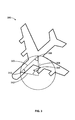
FIG. 3 , a turning radius example 300 is shown in the aircraft contest.Aircraft length 302 represents the length of the aircraft as determined by the distance from the front wheels to its intersection with a line connecting the right wheels and the left wheels.Radius 304 andRadius 312 illustrate multiple radii drawn from the terminals ofaircraft length 302.Φ 306 represents the steering angle.Line 302 andradii angles Φ 306 is known andline 302 is known, then 180= Φ- 2(x), where x equals the value ofangle 308 andangle 310. Thus,radii 304 and 312 (i.e., the turning radius) may be determined using the law of sines, per the above. With reference back to derive turningradius 402 may comprise the method of deriving a turning radius as described above with respect to theFIG. 3 . - In the embodiment shown in
FIG. 4 , calculatecompensation factor 106 includes calculating a compensation factor based upon the turning radius. Compensation factors may be predetermined and associated with various turning radii. In various embodiments, calculatecompensation factor 106 includes logic to calculate a compensation factor in response to a turning radius. Typically, the smaller the turning radius, the larger the compensation factor will be because at least one wheel will slow more significantly than during a turn with a longer turning radius. - In various embodiments, the calculation of a compensation factor may occur only when aircraft reference speed is within a particular range. At lower speeds, aircraft reference speed may not be reliably calculated. In addition, various locked wheel protection functionality logic has a dropout velocity, below which locked wheel protecting techniques will not occur. Thus, a compensation factor would be unnecessary. At higher speeds, a wheel may not slow to below the trigger velocity and/or a turn may be potentially unsafe due to the higher speed. Thus, it may be desirable to use an upper limit beyond which a compensation factor is not used. In various embodiments, it has been found that compensation factors may be applied at speeds of between about 5 knots to about 50 knots and more preferably between about 10 knots and about 30 knots.
-
FIG. 5 illustratescompensation factor curve 500. A simulation is run to plot compensation factors by aircraft reference speed. The y axis shows the compensation factor in knots and the x axis shows aircraft reference speed in knots.Curve 502 represents the compensation factor relationship:
- As used herein, the meaning of the term "non-transitory computer-readable medium" should be construed to exclude only those types of transitory computer-readable media which were found in In re Nuijten, 500 F.3d 1346 (Fed. Cir. 2007) to fall outside the scope of patentable subject matter under 35 U.S.C. § 101, so long as and to the extent In re Nuijten remains binding authority in the U.S. federal courts and is not overruled by a future case or statute. Stated another way, the term "computer-readable medium" should be construed in a manner that is as broad as legally permissible.
- Systems, methods and computer program products are provided. In the detailed description herein, references to "one embodiment", "an embodiment", "an example embodiment", etc., indicate that the embodiment described may include a particular feature, structure, or characteristic, but every embodiment may not necessarily include the particular feature, structure, or characteristic. Moreover, such phrases are not necessarily referring to the same embodiment. Further, when a particular feature, structure, or characteristic is described in connection with an embodiment, it is submitted that it is within the knowledge of one skilled in the art to effect such feature, structure, or characteristic in connection with other embodiments whether or not explicitly described. After reading the description, it will be apparent to one skilled in the relevant art(s) how to implement the disclosure in alternative embodiments.
- Benefits, other advantages, and solutions to problems have been described herein with regard to specific embodiments. However, the benefits, advantages, solutions to problems, and any elements that may cause any benefit, advantage, or solution to occur or become more pronounced are not to be construed as critical, required, or essential features or elements of the inventions. The scope of the inventions is accordingly to be limited by nothing other than the appended claims, in which reference to an element in the singular is not intended to mean "one and only one" unless explicitly so stated, but rather "one or more." Moreover, where a phrase similar to "at least one of A, B, or C" is used in the claims, it is intended that the phrase be interpreted to mean that A alone may be present in an embodiment, B alone may be present in an embodiment, C alone may be present in an embodiment, or that any combination of the elements A, B and C may be present in a single embodiment; for example, A and B, A and C, B and C, or A and B and C. Furthermore, no element, component, or method step in the present disclosure is intended to be dedicated to the public regardless of whether the element, component, or method step is explicitly recited in the claims. As used herein, the terms "comprises", "comprising", or any other variation thereof, are intended to cover a non-exclusive inclusion, such that a process, method, article, or apparatus that comprises a list of elements does not include only those elements but may include other elements not expressly listed or inherent to such process, method, article, or apparatus.
Claims (15)
- A method comprising
determining, at a brake controller, an aircraft reference speed for an aircraft having a first wheel and a second wheel;
identifying, at the brake controller, a state comprising the first wheel having a different rotational velocity than the second wheel, wherein the difference in rotational velocity sums to about zero;
calculating, at the brake controller, a compensation factor for at least one of the first wheel and the second wheel; and
adjusting, at the brake controller, a locked wheel trigger velocity in accordance with the compensation factor. - The method of claim 1, further comprising deriving a turning radius of the aircraft.
- The method of claim 2, wherein the calculating occurs in response to determining that the turning radius is below a threshold.
- The method of claim 1, wherein at least one of:-a) the aircraft reference speed remains constant;b) the adjusting occurs in response to the expiration of a preset amount of time.
- The method of claim 1, wherein the compensation factor is expressed as a percentage of the locked wheel trigger velocity.
- The method of claim 5, wherein the compensation factor is calculated using the formula:

wherein LW_DELTA represents the locked wheel trigger velocity. - A computer readable medium bearing instructions for braking, the instructions, when executed by a brake controller, cause the brake controller to perform operations comprising:determining, at the brake controller, an aircraft reference speed for an aircraft having a first wheel and a second wheel;identifying, at the brake controller, a state comprising the first wheel having a different rotational velocity than the second wheel, wherein the difference in rotational velocity sums to about zero;calculating, at the brake controller, a compensation factor for at least one of the first wheel and the second wheel; andadjusting, at the brake controller, a locked wheel trigger velocity in accordance with the compensation factor.
- The computer readable medium of claim 7, wherein the operation further comprise deriving a turning radius of the aircraft; and
optionally:-
the calculating occurs in response to determining that the turning radius is below a threshold. - The computer readable medium of claim 7, wherein at least one of:-a) the aircraft reference speed remains constant;b) the adjusting occurs in response to the expiration of a preset amount of time.
- The computer readable medium of claim 7, the compensation factor is expressed as a percentage of the locked wheel trigger velocity.
- The computer readable medium of claim 10, where the compensation factor is calculated using the formula:

wherein LW_DELTA represents the locked wheel trigger velocity. - A system comprising:a brake controller having locked wheel protection functionality comprising a locked wheel trigger velocity;a first wheel velocity sensor and a second wheel velocity sensor, wherein the first wheel velocity and the second wheel velocity are available to the brake controller;wherein the brake controller receives the identifies a state comprising the first wheel velocity is different from the second wheel velocity, wherein the difference in rotational velocity sums to about zero;
wherein the brake controller calculates a compensation factor for at least one of the first wheel and the second wheel; and
wherein the brake controller adjusts a locked wheel trigger velocity in accordance with the compensation factor. - The system of claim 12, wherein at least one of:-a) the brake controller derives a turning radius of an aircraft;b) the brake controller calculates in response to determining that the turning radius is below a threshold.
- The system of claim 12, wherein at least one of:-a) aircraft reference speed remains constant;b) the brake controller adjusts in response to the expiration of a preset amount of time.
- The system of claim 12, wherein the brake controller represents the compensation factor as a percentage of the locked wheel trigger velocity.
Applications Claiming Priority (1)
| Application Number | Priority Date | Filing Date | Title |
|---|---|---|---|
| US13/227,304 US8538654B2 (en) | 2011-09-07 | 2011-09-07 | Systems and methods for improved aircraft braking |
Publications (3)
| Publication Number | Publication Date |
|---|---|
| EP2567873A2 true EP2567873A2 (en) | 2013-03-13 |
| EP2567873A3 EP2567873A3 (en) | 2013-08-14 |
| EP2567873B1 EP2567873B1 (en) | 2016-11-16 |
Family
ID=46245937
Family Applications (1)
| Application Number | Title | Priority Date | Filing Date |
|---|---|---|---|
| EP12171669.0A Active EP2567873B1 (en) | 2011-09-07 | 2012-06-12 | Systems and methods for improved aircraft braking |
Country Status (2)
| Country | Link |
|---|---|
| US (1) | US8538654B2 (en) |
| EP (1) | EP2567873B1 (en) |
Cited By (1)
| Publication number | Priority date | Publication date | Assignee | Title |
|---|---|---|---|---|
| FR3010697A1 (en) * | 2013-09-13 | 2015-03-20 | Messier Bugatti Dowty | METHOD FOR BRAKING AN AIRCRAFT WITH SPEED MEASUREMENT CLOSE TO BRAKE WHEELS. |
Families Citing this family (3)
| Publication number | Priority date | Publication date | Assignee | Title |
|---|---|---|---|---|
| US8965657B2 (en) * | 2013-07-02 | 2015-02-24 | Goodrich Corporation | System and method for detecting an on ground condition of an aircraft |
| CN106672219B (en) * | 2016-12-22 | 2019-02-15 | 西安航空制动科技有限公司 | A method for aircraft anti-skid failure speed state locking |
| CN112874494B (en) * | 2021-03-10 | 2022-04-05 | 北京航空航天大学 | Aircraft braking method and device |
Family Cites Families (11)
| Publication number | Priority date | Publication date | Assignee | Title |
|---|---|---|---|---|
| BE794514A (en) * | 1972-02-08 | 1973-05-16 | Citroen Sa | IMPROVEMENTS MADE TO THE BRAKE CONTROL DEVICES OF A VEHICLE |
| US3880475A (en) * | 1972-03-29 | 1975-04-29 | Goodyear Tire & Rubber | Anti-skid system |
| JP2627432B2 (en) * | 1988-07-18 | 1997-07-09 | 本田技研工業株式会社 | Method of estimating body speed of four-wheeled vehicle |
| JP2844542B2 (en) * | 1989-12-27 | 1999-01-06 | 株式会社曙ブレーキ中央技術研究所 | Vehicle anti-lock control method |
| US6132016A (en) * | 1997-05-02 | 2000-10-17 | Hydro-Aire, Inc. | System and method for adaptive brake application and initial skid detection |
| US6722745B2 (en) * | 1997-05-02 | 2004-04-20 | Hydro-Aire, Inc. | System and method for adaptive brake application and initial skid detection |
| US6220676B1 (en) * | 1997-05-09 | 2001-04-24 | The B. F. Goodrich Company | Antiskid control of multi-wheel vehicles using coupled and decoupled Kalman filtering incorporating pitch weight transfer |
| DE10143031C1 (en) * | 2001-09-01 | 2003-04-17 | Bayerische Motoren Werke Ag | Vehicle braking force enhancement method for anti-locking braking system adjusts slip threshold value dependent on curvature radius, braking pressure variation and friction value of road surface |
| US6684147B2 (en) * | 2001-12-17 | 2004-01-27 | Hydro-Aire, Inc. | Sliding integral proportional (SIP) controller for aircraft skid control |
| JP4342175B2 (en) * | 2002-12-27 | 2009-10-14 | トヨタ自動車株式会社 | Braking system |
| FR2910417B1 (en) * | 2006-12-21 | 2012-07-06 | Messier Bugatti | ADAPTIVE BRAKING CONTROL METHOD FOR VEHICLE. |
-
2011
- 2011-09-07 US US13/227,304 patent/US8538654B2/en active Active
-
2012
- 2012-06-12 EP EP12171669.0A patent/EP2567873B1/en active Active
Non-Patent Citations (1)
| Title |
|---|
| None |
Cited By (3)
| Publication number | Priority date | Publication date | Assignee | Title |
|---|---|---|---|---|
| FR3010697A1 (en) * | 2013-09-13 | 2015-03-20 | Messier Bugatti Dowty | METHOD FOR BRAKING AN AIRCRAFT WITH SPEED MEASUREMENT CLOSE TO BRAKE WHEELS. |
| WO2015036520A3 (en) * | 2013-09-13 | 2015-09-03 | Messier-Bugatti-Dowty | Method for managing the braking of an aircraft with speed measurement close to the braked wheels |
| US9914531B2 (en) | 2013-09-13 | 2018-03-13 | Messier-Bugatti-Dowty | Method for managing the braking of an aircraft with speed measurement close to the braked wheels |
Also Published As
| Publication number | Publication date |
|---|---|
| US8538654B2 (en) | 2013-09-17 |
| EP2567873B1 (en) | 2016-11-16 |
| EP2567873A3 (en) | 2013-08-14 |
| US20130060441A1 (en) | 2013-03-07 |
Similar Documents
| Publication | Publication Date | Title |
|---|---|---|
| EP2684752B1 (en) | Method for dragging brake detection | |
| EP1993891B1 (en) | Method and system to increase electric brake clamping force accuracy | |
| EP1693262B1 (en) | Method and system to reduce carbon brake wear through residual brake force | |
| CN102099230B (en) | Method of maintaining optimal braking and skid protection for a two-wheeled vehicle having a speed sensor failure on a single wheel | |
| EP2899079B1 (en) | Optimized real-time antiskid control initialization for travel surfaces as a function of wheel spinup | |
| EP3875323B1 (en) | Systems and methods for aircraft antiskid braking | |
| EP3556619B1 (en) | Energy-based antiskid brake control system | |
| US8538654B2 (en) | Systems and methods for improved aircraft braking | |
| CN105934379B (en) | It is measured for aircraft brake to mitigate the system and method for structural load | |
| EP4574595A1 (en) | Brake coefficient of friction (ì) estimation for prognostics and health management (phm) and improved load balance (lb) | |
| KR102143495B1 (en) | Apparatus for braking control of vehicle and method thereof |
Legal Events
| Date | Code | Title | Description |
|---|---|---|---|
| PUAI | Public reference made under article 153(3) epc to a published international application that has entered the european phase |
Free format text: ORIGINAL CODE: 0009012 |
|
| 17P | Request for examination filed |
Effective date: 20120612 |
|
| AK | Designated contracting states |
Kind code of ref document: A2 Designated state(s): AL AT BE BG CH CY CZ DE DK EE ES FI FR GB GR HR HU IE IS IT LI LT LU LV MC MK MT NL NO PL PT RO RS SE SI SK SM TR |
|
| AX | Request for extension of the european patent |
Extension state: BA ME |
|
| PUAL | Search report despatched |
Free format text: ORIGINAL CODE: 0009013 |
|
| AK | Designated contracting states |
Kind code of ref document: A3 Designated state(s): AL AT BE BG CH CY CZ DE DK EE ES FI FR GB GR HR HU IE IS IT LI LT LU LV MC MK MT NL NO PL PT RO RS SE SI SK SM TR |
|
| AX | Request for extension of the european patent |
Extension state: BA ME |
|
| RIC1 | Information provided on ipc code assigned before grant |
Ipc: B60T 8/172 20060101ALI20130709BHEP Ipc: B60T 8/17 20060101AFI20130709BHEP |
|
| GRAP | Despatch of communication of intention to grant a patent |
Free format text: ORIGINAL CODE: EPIDOSNIGR1 |
|
| INTG | Intention to grant announced |
Effective date: 20160620 |
|
| GRAS | Grant fee paid |
Free format text: ORIGINAL CODE: EPIDOSNIGR3 |
|
| GRAA | (expected) grant |
Free format text: ORIGINAL CODE: 0009210 |
|
| AK | Designated contracting states |
Kind code of ref document: B1 Designated state(s): AL AT BE BG CH CY CZ DE DK EE ES FI FR GB GR HR HU IE IS IT LI LT LU LV MC MK MT NL NO PL PT RO RS SE SI SK SM TR |
|
| REG | Reference to a national code |
Ref country code: GB Ref legal event code: FG4D |
|
| REG | Reference to a national code |
Ref country code: CH Ref legal event code: EP |
|
| REG | Reference to a national code |
Ref country code: IE Ref legal event code: FG4D |
|
| REG | Reference to a national code |
Ref country code: AT Ref legal event code: REF Ref document number: 845592 Country of ref document: AT Kind code of ref document: T Effective date: 20161215 |
|
| REG | Reference to a national code |
Ref country code: DE Ref legal event code: R096 Ref document number: 602012025347 Country of ref document: DE |
|
| PG25 | Lapsed in a contracting state [announced via postgrant information from national office to epo] |
Ref country code: LV Free format text: LAPSE BECAUSE OF FAILURE TO SUBMIT A TRANSLATION OF THE DESCRIPTION OR TO PAY THE FEE WITHIN THE PRESCRIBED TIME-LIMIT Effective date: 20161116 |
|
| REG | Reference to a national code |
Ref country code: NL Ref legal event code: MP Effective date: 20161116 |
|
| REG | Reference to a national code |
Ref country code: LT Ref legal event code: MG4D |
|
| REG | Reference to a national code |
Ref country code: AT Ref legal event code: MK05 Ref document number: 845592 Country of ref document: AT Kind code of ref document: T Effective date: 20161116 |
|
| PG25 | Lapsed in a contracting state [announced via postgrant information from national office to epo] |
Ref country code: NL Free format text: LAPSE BECAUSE OF FAILURE TO SUBMIT A TRANSLATION OF THE DESCRIPTION OR TO PAY THE FEE WITHIN THE PRESCRIBED TIME-LIMIT Effective date: 20161116 Ref country code: LT Free format text: LAPSE BECAUSE OF FAILURE TO SUBMIT A TRANSLATION OF THE DESCRIPTION OR TO PAY THE FEE WITHIN THE PRESCRIBED TIME-LIMIT Effective date: 20161116 Ref country code: SE Free format text: LAPSE BECAUSE OF FAILURE TO SUBMIT A TRANSLATION OF THE DESCRIPTION OR TO PAY THE FEE WITHIN THE PRESCRIBED TIME-LIMIT Effective date: 20161116 Ref country code: GR Free format text: LAPSE BECAUSE OF FAILURE TO SUBMIT A TRANSLATION OF THE DESCRIPTION OR TO PAY THE FEE WITHIN THE PRESCRIBED TIME-LIMIT Effective date: 20170217 Ref country code: NO Free format text: LAPSE BECAUSE OF FAILURE TO SUBMIT A TRANSLATION OF THE DESCRIPTION OR TO PAY THE FEE WITHIN THE PRESCRIBED TIME-LIMIT Effective date: 20170216 |
|
| REG | Reference to a national code |
Ref country code: FR Ref legal event code: PLFP Year of fee payment: 6 |
|
| PG25 | Lapsed in a contracting state [announced via postgrant information from national office to epo] |
Ref country code: HR Free format text: LAPSE BECAUSE OF FAILURE TO SUBMIT A TRANSLATION OF THE DESCRIPTION OR TO PAY THE FEE WITHIN THE PRESCRIBED TIME-LIMIT Effective date: 20161116 Ref country code: PT Free format text: LAPSE BECAUSE OF FAILURE TO SUBMIT A TRANSLATION OF THE DESCRIPTION OR TO PAY THE FEE WITHIN THE PRESCRIBED TIME-LIMIT Effective date: 20170316 Ref country code: RS Free format text: LAPSE BECAUSE OF FAILURE TO SUBMIT A TRANSLATION OF THE DESCRIPTION OR TO PAY THE FEE WITHIN THE PRESCRIBED TIME-LIMIT Effective date: 20161116 Ref country code: FI Free format text: LAPSE BECAUSE OF FAILURE TO SUBMIT A TRANSLATION OF THE DESCRIPTION OR TO PAY THE FEE WITHIN THE PRESCRIBED TIME-LIMIT Effective date: 20161116 Ref country code: ES Free format text: LAPSE BECAUSE OF FAILURE TO SUBMIT A TRANSLATION OF THE DESCRIPTION OR TO PAY THE FEE WITHIN THE PRESCRIBED TIME-LIMIT Effective date: 20161116 Ref country code: AT Free format text: LAPSE BECAUSE OF FAILURE TO SUBMIT A TRANSLATION OF THE DESCRIPTION OR TO PAY THE FEE WITHIN THE PRESCRIBED TIME-LIMIT Effective date: 20161116 Ref country code: PL Free format text: LAPSE BECAUSE OF FAILURE TO SUBMIT A TRANSLATION OF THE DESCRIPTION OR TO PAY THE FEE WITHIN THE PRESCRIBED TIME-LIMIT Effective date: 20161116 |
|
| PG25 | Lapsed in a contracting state [announced via postgrant information from national office to epo] |
Ref country code: CZ Free format text: LAPSE BECAUSE OF FAILURE TO SUBMIT A TRANSLATION OF THE DESCRIPTION OR TO PAY THE FEE WITHIN THE PRESCRIBED TIME-LIMIT Effective date: 20161116 Ref country code: SK Free format text: LAPSE BECAUSE OF FAILURE TO SUBMIT A TRANSLATION OF THE DESCRIPTION OR TO PAY THE FEE WITHIN THE PRESCRIBED TIME-LIMIT Effective date: 20161116 Ref country code: DK Free format text: LAPSE BECAUSE OF FAILURE TO SUBMIT A TRANSLATION OF THE DESCRIPTION OR TO PAY THE FEE WITHIN THE PRESCRIBED TIME-LIMIT Effective date: 20161116 Ref country code: EE Free format text: LAPSE BECAUSE OF FAILURE TO SUBMIT A TRANSLATION OF THE DESCRIPTION OR TO PAY THE FEE WITHIN THE PRESCRIBED TIME-LIMIT Effective date: 20161116 Ref country code: RO Free format text: LAPSE BECAUSE OF FAILURE TO SUBMIT A TRANSLATION OF THE DESCRIPTION OR TO PAY THE FEE WITHIN THE PRESCRIBED TIME-LIMIT Effective date: 20161116 |
|
| REG | Reference to a national code |
Ref country code: DE Ref legal event code: R097 Ref document number: 602012025347 Country of ref document: DE |
|
| PG25 | Lapsed in a contracting state [announced via postgrant information from national office to epo] |
Ref country code: SM Free format text: LAPSE BECAUSE OF FAILURE TO SUBMIT A TRANSLATION OF THE DESCRIPTION OR TO PAY THE FEE WITHIN THE PRESCRIBED TIME-LIMIT Effective date: 20161116 Ref country code: IT Free format text: LAPSE BECAUSE OF FAILURE TO SUBMIT A TRANSLATION OF THE DESCRIPTION OR TO PAY THE FEE WITHIN THE PRESCRIBED TIME-LIMIT Effective date: 20161116 Ref country code: BG Free format text: LAPSE BECAUSE OF FAILURE TO SUBMIT A TRANSLATION OF THE DESCRIPTION OR TO PAY THE FEE WITHIN THE PRESCRIBED TIME-LIMIT Effective date: 20170216 Ref country code: BE Free format text: LAPSE BECAUSE OF FAILURE TO SUBMIT A TRANSLATION OF THE DESCRIPTION OR TO PAY THE FEE WITHIN THE PRESCRIBED TIME-LIMIT Effective date: 20161116 |
|
| PLBE | No opposition filed within time limit |
Free format text: ORIGINAL CODE: 0009261 |
|
| STAA | Information on the status of an ep patent application or granted ep patent |
Free format text: STATUS: NO OPPOSITION FILED WITHIN TIME LIMIT |
|
| 26N | No opposition filed |
Effective date: 20170817 |
|
| PG25 | Lapsed in a contracting state [announced via postgrant information from national office to epo] |
Ref country code: SI Free format text: LAPSE BECAUSE OF FAILURE TO SUBMIT A TRANSLATION OF THE DESCRIPTION OR TO PAY THE FEE WITHIN THE PRESCRIBED TIME-LIMIT Effective date: 20161116 |
|
| REG | Reference to a national code |
Ref country code: DE Ref legal event code: R119 Ref document number: 602012025347 Country of ref document: DE |
|
| PG25 | Lapsed in a contracting state [announced via postgrant information from national office to epo] |
Ref country code: MC Free format text: LAPSE BECAUSE OF FAILURE TO SUBMIT A TRANSLATION OF THE DESCRIPTION OR TO PAY THE FEE WITHIN THE PRESCRIBED TIME-LIMIT Effective date: 20161116 |
|
| REG | Reference to a national code |
Ref country code: CH Ref legal event code: PL |
|
| REG | Reference to a national code |
Ref country code: IE Ref legal event code: MM4A |
|
| PG25 | Lapsed in a contracting state [announced via postgrant information from national office to epo] |
Ref country code: DE Free format text: LAPSE BECAUSE OF NON-PAYMENT OF DUE FEES Effective date: 20180103 Ref country code: LU Free format text: LAPSE BECAUSE OF NON-PAYMENT OF DUE FEES Effective date: 20170612 Ref country code: LI Free format text: LAPSE BECAUSE OF NON-PAYMENT OF DUE FEES Effective date: 20170630 Ref country code: IE Free format text: LAPSE BECAUSE OF NON-PAYMENT OF DUE FEES Effective date: 20170612 Ref country code: CH Free format text: LAPSE BECAUSE OF NON-PAYMENT OF DUE FEES Effective date: 20170630 |
|
| REG | Reference to a national code |
Ref country code: FR Ref legal event code: PLFP Year of fee payment: 7 |
|
| PG25 | Lapsed in a contracting state [announced via postgrant information from national office to epo] |
Ref country code: MT Free format text: LAPSE BECAUSE OF NON-PAYMENT OF DUE FEES Effective date: 20170612 |
|
| PG25 | Lapsed in a contracting state [announced via postgrant information from national office to epo] |
Ref country code: HU Free format text: LAPSE BECAUSE OF FAILURE TO SUBMIT A TRANSLATION OF THE DESCRIPTION OR TO PAY THE FEE WITHIN THE PRESCRIBED TIME-LIMIT; INVALID AB INITIO Effective date: 20120612 |
|
| PG25 | Lapsed in a contracting state [announced via postgrant information from national office to epo] |
Ref country code: CY Free format text: LAPSE BECAUSE OF NON-PAYMENT OF DUE FEES Effective date: 20161116 |
|
| PG25 | Lapsed in a contracting state [announced via postgrant information from national office to epo] |
Ref country code: MK Free format text: LAPSE BECAUSE OF FAILURE TO SUBMIT A TRANSLATION OF THE DESCRIPTION OR TO PAY THE FEE WITHIN THE PRESCRIBED TIME-LIMIT Effective date: 20161116 |
|
| PG25 | Lapsed in a contracting state [announced via postgrant information from national office to epo] |
Ref country code: TR Free format text: LAPSE BECAUSE OF FAILURE TO SUBMIT A TRANSLATION OF THE DESCRIPTION OR TO PAY THE FEE WITHIN THE PRESCRIBED TIME-LIMIT Effective date: 20161116 |
|
| PG25 | Lapsed in a contracting state [announced via postgrant information from national office to epo] |
Ref country code: AL Free format text: LAPSE BECAUSE OF FAILURE TO SUBMIT A TRANSLATION OF THE DESCRIPTION OR TO PAY THE FEE WITHIN THE PRESCRIBED TIME-LIMIT Effective date: 20161116 Ref country code: IS Free format text: LAPSE BECAUSE OF FAILURE TO SUBMIT A TRANSLATION OF THE DESCRIPTION OR TO PAY THE FEE WITHIN THE PRESCRIBED TIME-LIMIT Effective date: 20170316 |
|
| P01 | Opt-out of the competence of the unified patent court (upc) registered |
Effective date: 20230522 |
|
| PGFP | Annual fee paid to national office [announced via postgrant information from national office to epo] |
Ref country code: GB Payment date: 20250520 Year of fee payment: 14 |
|
| PGFP | Annual fee paid to national office [announced via postgrant information from national office to epo] |
Ref country code: FR Payment date: 20250520 Year of fee payment: 14 |