EP2567858A2 - Control apparatus for hybrid electric vehicle - Google Patents
Control apparatus for hybrid electric vehicle Download PDFInfo
- Publication number
- EP2567858A2 EP2567858A2 EP12183561A EP12183561A EP2567858A2 EP 2567858 A2 EP2567858 A2 EP 2567858A2 EP 12183561 A EP12183561 A EP 12183561A EP 12183561 A EP12183561 A EP 12183561A EP 2567858 A2 EP2567858 A2 EP 2567858A2
- Authority
- EP
- European Patent Office
- Prior art keywords
- temperature
- engine
- battery
- increase rate
- control apparatus
- Prior art date
- Legal status (The legal status is an assumption and is not a legal conclusion. Google has not performed a legal analysis and makes no representation as to the accuracy of the status listed.)
- Granted
Links
Images


Classifications
-
- B—PERFORMING OPERATIONS; TRANSPORTING
- B60—VEHICLES IN GENERAL
- B60W—CONJOINT CONTROL OF VEHICLE SUB-UNITS OF DIFFERENT TYPE OR DIFFERENT FUNCTION; CONTROL SYSTEMS SPECIALLY ADAPTED FOR HYBRID VEHICLES; ROAD VEHICLE DRIVE CONTROL SYSTEMS FOR PURPOSES NOT RELATED TO THE CONTROL OF A PARTICULAR SUB-UNIT
- B60W10/00—Conjoint control of vehicle sub-units of different type or different function
- B60W10/24—Conjoint control of vehicle sub-units of different type or different function including control of energy storage means
- B60W10/26—Conjoint control of vehicle sub-units of different type or different function including control of energy storage means for electrical energy, e.g. batteries or capacitors
-
- B—PERFORMING OPERATIONS; TRANSPORTING
- B60—VEHICLES IN GENERAL
- B60L—PROPULSION OF ELECTRICALLY-PROPELLED VEHICLES; SUPPLYING ELECTRIC POWER FOR AUXILIARY EQUIPMENT OF ELECTRICALLY-PROPELLED VEHICLES; ELECTRODYNAMIC BRAKE SYSTEMS FOR VEHICLES IN GENERAL; MAGNETIC SUSPENSION OR LEVITATION FOR VEHICLES; MONITORING OPERATING VARIABLES OF ELECTRICALLY-PROPELLED VEHICLES; ELECTRIC SAFETY DEVICES FOR ELECTRICALLY-PROPELLED VEHICLES
- B60L58/00—Methods or circuit arrangements for monitoring or controlling batteries or fuel cells, specially adapted for electric vehicles
- B60L58/10—Methods or circuit arrangements for monitoring or controlling batteries or fuel cells, specially adapted for electric vehicles for monitoring or controlling batteries
- B60L58/24—Methods or circuit arrangements for monitoring or controlling batteries or fuel cells, specially adapted for electric vehicles for monitoring or controlling batteries for controlling the temperature of batteries
- B60L58/25—Methods or circuit arrangements for monitoring or controlling batteries or fuel cells, specially adapted for electric vehicles for monitoring or controlling batteries for controlling the temperature of batteries by controlling the electric load
-
- B—PERFORMING OPERATIONS; TRANSPORTING
- B60—VEHICLES IN GENERAL
- B60W—CONJOINT CONTROL OF VEHICLE SUB-UNITS OF DIFFERENT TYPE OR DIFFERENT FUNCTION; CONTROL SYSTEMS SPECIALLY ADAPTED FOR HYBRID VEHICLES; ROAD VEHICLE DRIVE CONTROL SYSTEMS FOR PURPOSES NOT RELATED TO THE CONTROL OF A PARTICULAR SUB-UNIT
- B60W10/00—Conjoint control of vehicle sub-units of different type or different function
- B60W10/04—Conjoint control of vehicle sub-units of different type or different function including control of propulsion units
- B60W10/06—Conjoint control of vehicle sub-units of different type or different function including control of propulsion units including control of combustion engines
-
- B—PERFORMING OPERATIONS; TRANSPORTING
- B60—VEHICLES IN GENERAL
- B60W—CONJOINT CONTROL OF VEHICLE SUB-UNITS OF DIFFERENT TYPE OR DIFFERENT FUNCTION; CONTROL SYSTEMS SPECIALLY ADAPTED FOR HYBRID VEHICLES; ROAD VEHICLE DRIVE CONTROL SYSTEMS FOR PURPOSES NOT RELATED TO THE CONTROL OF A PARTICULAR SUB-UNIT
- B60W10/00—Conjoint control of vehicle sub-units of different type or different function
- B60W10/04—Conjoint control of vehicle sub-units of different type or different function including control of propulsion units
- B60W10/08—Conjoint control of vehicle sub-units of different type or different function including control of propulsion units including control of electric propulsion units, e.g. motors or generators
-
- B—PERFORMING OPERATIONS; TRANSPORTING
- B60—VEHICLES IN GENERAL
- B60W—CONJOINT CONTROL OF VEHICLE SUB-UNITS OF DIFFERENT TYPE OR DIFFERENT FUNCTION; CONTROL SYSTEMS SPECIALLY ADAPTED FOR HYBRID VEHICLES; ROAD VEHICLE DRIVE CONTROL SYSTEMS FOR PURPOSES NOT RELATED TO THE CONTROL OF A PARTICULAR SUB-UNIT
- B60W20/00—Control systems specially adapted for hybrid vehicles
-
- B—PERFORMING OPERATIONS; TRANSPORTING
- B60—VEHICLES IN GENERAL
- B60L—PROPULSION OF ELECTRICALLY-PROPELLED VEHICLES; SUPPLYING ELECTRIC POWER FOR AUXILIARY EQUIPMENT OF ELECTRICALLY-PROPELLED VEHICLES; ELECTRODYNAMIC BRAKE SYSTEMS FOR VEHICLES IN GENERAL; MAGNETIC SUSPENSION OR LEVITATION FOR VEHICLES; MONITORING OPERATING VARIABLES OF ELECTRICALLY-PROPELLED VEHICLES; ELECTRIC SAFETY DEVICES FOR ELECTRICALLY-PROPELLED VEHICLES
- B60L2240/00—Control parameters of input or output; Target parameters
- B60L2240/40—Drive Train control parameters
- B60L2240/54—Drive Train control parameters related to batteries
- B60L2240/545—Temperature
-
- B—PERFORMING OPERATIONS; TRANSPORTING
- B60—VEHICLES IN GENERAL
- B60W—CONJOINT CONTROL OF VEHICLE SUB-UNITS OF DIFFERENT TYPE OR DIFFERENT FUNCTION; CONTROL SYSTEMS SPECIALLY ADAPTED FOR HYBRID VEHICLES; ROAD VEHICLE DRIVE CONTROL SYSTEMS FOR PURPOSES NOT RELATED TO THE CONTROL OF A PARTICULAR SUB-UNIT
- B60W2510/00—Input parameters relating to a particular sub-units
- B60W2510/24—Energy storage means
- B60W2510/242—Energy storage means for electrical energy
- B60W2510/246—Temperature
-
- Y—GENERAL TAGGING OF NEW TECHNOLOGICAL DEVELOPMENTS; GENERAL TAGGING OF CROSS-SECTIONAL TECHNOLOGIES SPANNING OVER SEVERAL SECTIONS OF THE IPC; TECHNICAL SUBJECTS COVERED BY FORMER USPC CROSS-REFERENCE ART COLLECTIONS [XRACs] AND DIGESTS
- Y02—TECHNOLOGIES OR APPLICATIONS FOR MITIGATION OR ADAPTATION AGAINST CLIMATE CHANGE
- Y02T—CLIMATE CHANGE MITIGATION TECHNOLOGIES RELATED TO TRANSPORTATION
- Y02T10/00—Road transport of goods or passengers
- Y02T10/60—Other road transportation technologies with climate change mitigation effect
- Y02T10/62—Hybrid vehicles
-
- Y—GENERAL TAGGING OF NEW TECHNOLOGICAL DEVELOPMENTS; GENERAL TAGGING OF CROSS-SECTIONAL TECHNOLOGIES SPANNING OVER SEVERAL SECTIONS OF THE IPC; TECHNICAL SUBJECTS COVERED BY FORMER USPC CROSS-REFERENCE ART COLLECTIONS [XRACs] AND DIGESTS
- Y02—TECHNOLOGIES OR APPLICATIONS FOR MITIGATION OR ADAPTATION AGAINST CLIMATE CHANGE
- Y02T—CLIMATE CHANGE MITIGATION TECHNOLOGIES RELATED TO TRANSPORTATION
- Y02T10/00—Road transport of goods or passengers
- Y02T10/60—Other road transportation technologies with climate change mitigation effect
- Y02T10/70—Energy storage systems for electromobility, e.g. batteries
Definitions
- the present invention relates to control apparatuses for hybrid electric vehicles.
- Examples of known hybrid electric vehicles include one in which an electric current is supplied to a motor from each of a battery and a generator driven by an engine, and a driving wheel is driven by driving torque outputted from the motor.
- a technique for preventing battery degradation there is proposed a technique (related art) in which a depth of discharge of a battery is calculated based on the temperature of the battery, and when the rate of increase in battery temperature is high, a generator is activated in a state where the depth of discharge is low (see Japanese Patent No. 3707206 ).
- This invention provides a control apparatus for a hybrid electric vehicle, which is advantageous in suppressing battery degradation caused by an excessive increase in battery temperature, while suppressing a reduction in fuel efficiency.
- An aspect of the invention provides a control apparatus for a hybrid electric vehicle comprising: an electric motor configured to drive a driving wheel of the hybrid electric vehicle; a battery configured to supply an electric current to the electric motor; a generator configured to supply an electric current to the electric motor; and an engine configured to allow the generator to generate electric power
- the control apparatus comprising: a temperature detector configured to detect a temperature of the battery; a temperature increase rate calculator configured to calculate, based on the detected temperature of the battery, a temperature increase rate that is an amount of increase in the temperature per unit time; and an engine controller configured to allow, when the temperature increase rate is equal to or higher than a threshold value, the engine to be started, so that the generator generates the electric power, wherein the threshold value is set so that the higher the detected battery temperature, the lower the threshold value.
- the engine controller may control the engine so that the higher the temperature increase rate, the larger an electric power generation amount of the generator.
- the engine controller may allow start of the engine when the detected temperature of the battery is equal to or higher than a preset first temperature, and disallow start of the engine when the detected temperature of the battery is lower the first temperature.
- the engine controller may stop the engine when a period during which the detected temperature of the battery is continuously lower than a second preset temperature after start of the engine is equal to or longer than a preset period.
- the vehicle 10 includes: a high voltage battery 12; inverters 14 and 16; a front motor 18 serving as an electric motor; a rear motor 20 serving as an electric motor; an engine 22 serving as an internal combustion engine; a generator 24; front wheels 26; rear wheels 28; and a control apparatus 30 according to the present invention.
- the vehicle 10 constitutes a hybrid electric vehicle on which the motors 18 and 20 and the engine 22 are installed.
- the high voltage battery 12 supplies electric power to the front and rear motors 18 and 20. Further, an electric current, supplied from the high voltage battery 12 to the front and rear motors 18 and 20, will herein be referred to as a "battery current".
- the high voltage battery 12 is charged with electric power supplied from, for example, a domestic commercial power supply or a quick-charging power supply of a charging station via unillustrated charging equipment.
- the inverters 14 and 16 convert DC electric power, supplied from the high voltage battery 12, into three-phase AC electric power, and supply the three-phase AC electric power to the front and rear motors 18 and 20, respectively.
- the three-phase AC electric power which is supplied to the front and rear motors 18 and 20, is controlled by the inverters 14 and 16 by using PWM (pulse width modulation), for example, thereby controlling driving torque outputted from the front and rear motors 18 and 20.
- PWM pulse width modulation
- the front motor 18 is driven and rotated by the AC electric power supplied from the inverter 14, and provides power (driving torque) to the front wheels 26 via a speed reducer 32 and a differential gear 34, thereby driving the front wheels 26.
- the rear motor 20 is driven and rotated by the three-phase AC electric power supplied from the inverter 16, and provides power (driving torque) to the rear wheels 28 via a speed reducer 36 and a differential gear 38, thereby driving the rear wheels 28.
- the front and rear motors 18 and 20 each function as a generator, and three-phase AC electric power generated by the front and rear motors 18 and 20 is converted into DC electric power via the inverters 14 and 16; then, the high voltage battery 12 is charged with the DC electric power.
- the motors 18 and 20 each incorporate a motor coil, and are each driven and rotated by an electric current (battery current) flowing through its motor coil.
- the motors 18 and 20 have characteristics that simultaneously with start of supply of an electric current, a transient large electric current, which is called a "rush current", temporarily flows through the motors 18 and 20.
- the engine 22 is connected to the speed reducer 32 via a speed reducer 40 and a clutch 42. Engagement and disengagement of the clutch 42 is controlled by the ECU.
- the engine 22 When the clutch 42 is in a disengaged state, the engine 22 provides power to the generator 24 via a speed reducer 41 and thus drives the generator 24.
- the generator 24 generates electric power by the power supplied from the engine 22, and charges the high voltage battery 12 via the inverter 14.
- the engine 22 is started to allow the generator 24 to generate electric power; then, the electric power (electric current) generated by the generator 24 is supplied to the front motor 18 (and/or the rear motor 20), and in addition, the high voltage battery 12 is charged with electric power (electric current) that has not been consumed by driving of the front motor 18 (and/or the rear motor 20).
- the electric current supplied from the generator 24 is added to the battery current supplied from the high voltage battery 12, and the resulting electric current is supplied to the front motor 18 and/or the rear motor 20.
- the present invention is also naturally applicable to a case where the vehicle 10 travels by using only the rear motor 20, or a case where the vehicle 10 travels by using both of the front and rear motors 18 and 20.
- the present invention is also naturally applicable to a case where when the clutch 42 is in the engaged state, the engine 22 provides power to the generator 24 via the speed reducer 41 and thus drives the generator 24, while the engine 22 provides power (driving torque) to the front wheels 26 via the speed reducer 40, the clutch 42, the speed reducer 32 and the differential gear 34 and thus drives the front wheels 26.
- the control apparatus 30 includes: an accelerator pedal sensor 44; a battery temperature sensor 46; and the ECU 48.
- the accelerator pedal sensor 44 detects an accelerator pedal pressing amount, and supplies the detected value to the ECU 48.
- the battery temperature sensor 46 detects a temperature of the high voltage battery 12 (which will hereinafter be referred to as a "battery temperature TB"), and supplies the detected value to the ECU 48.
- the battery temperature sensor 46 constitutes a "temperature detector”.
- the ECU 48 includes: a CPU; a ROM for storing/retaining a control program or the like; a RAM serving as an area where the control program is operated; and an interface section serving as an interface between the ECU 48 and a peripheral circuit or the like.
- the ECU 48 executes the control program, thereby implementing: a motor control unit 48A; a temperature increase rate calculating unit 48B; an engine control unit 48C; and an engine start determination value setting unit 48D.
- the engine control unit 48C and the engine start determination value setting unit 48D constitute an "engine controller".
- the motor control unit 48A controls the electric current, supplied to the front motor 18 from the high voltage battery 12, in accordance with the accelerator pedal pressing amount detected by the accelerator pedal sensor 44, i.e., in accordance with the required driving torque.
- the temperature increase rate calculating unit 48B calculates, based on the battery temperature TB detected by the battery temperature sensor 46, a temperature increase rate ⁇ that is an amount of increase in the battery temperature TB per unit time.
- the temperature increase rate ⁇ is defined by ⁇ TB/ ⁇ t.
- the engine control unit 48C controls, for example, the start, stop and RPM of the engine 22.
- the temperature increase rate ⁇ calculated by the temperature increase rate calculating unit 48B is equal to or higher than an engine start determination value ⁇ 1 that is a preset threshold value, the engine control unit 48C starts the engine 22, thereby activating the generator 24.
- the engine control unit 48C controls the engine 22 so that the higher the temperature increase rate ⁇ , the larger the electric power generation amount of the generator 24 will be. In other words, the engine control unit 48C controls the engine 22 so that the higher the temperature increase rate ⁇ , the higher the RPM of the engine 22 will be.
- the engine control unit 48C includes an electric power generation amount map 50.
- the electric power generation amount map 50 is a map illustrating a relationship between the temperature increase rate ⁇ and electric power generation amount P (kW).
- the engine control unit 48C identifies the electric power generation amount P from the temperature increase rate ⁇ based on the electric power generation amount map 50, and controls the RPM of the engine 22 (or controls driving of the engine 22) so that the electric power generation amount P is generated by the generator 24.
- the engine control unit 48C allows the start of the engine 22; on the other hand, when the detected battery temperature TB is below the first threshold temperature TB1, the engine control unit 48C disallows the start of the engine 22.
- the first threshold temperature TB1 is set as a temperature at which no consideration has to be given to degradation of the high voltage battery 12 because even if a pronounced temperature increase has occurred, the battery temperature TB is originally low as long as the battery temperature TB is below the first threshold temperature TB1.
- the first threshold temperature TB1 is set at room temperature (25°), for example.
- the engine control unit 48C stops the engine 22 upon satisfaction of an engine stop requirement after the start of the engine 22.
- the engine stop requirement is that a period during which the battery temperature TB detected by the battery temperature sensor 46 is continuously below a second threshold temperature TB2 (which is a second given temperature set in advance) must be equal to or longer than a threshold period (which is a given period set in advance) .
- the second threshold temperature TB2 is set as a temperature that allows degradation of the high voltage battery 12 to be ignored as long as the battery temperature TB is below the second threshold temperature TB2. Note that the engine stop requirement is not limited to this example but any requirement may be set.
- the engine start determination value setting unit 48D sets the engine start determination value ⁇ 1 so that the higher the battery temperature TB detected by the battery temperature sensor 46, the lower the engine start determination value ⁇ 1 will be.
- the engine start determination value setting unit 48D includes a start determination value map 52.
- the start determination value map 52 is a map illustrating a relationship between the battery temperature TB and the engine start determination value ⁇ 1.
- the engine start determination value setting unit 48D identifies and sets the engine start determination value ⁇ 1 from the battery temperature TB based on the start determination value map 52.
- Processing illustrated in FIG. 6 is carried out repeatedly when normal traveling of the vehicle 10 is performed by using the motor 18 with the engine 22 stopped.
- the ECU 48 determines whether or not the engine 22 is stopped (Step S10).
- Step S10 the ECU 48 skips the subsequent processes and returns the processing.
- Step S10 the ECU 48 determines whether or not the battery temperature TB detected by the battery temperature sensor 46 is equal to or higher than the first threshold temperature TB1 (Step S12).
- Step S12 the ECU 48 skips the subsequent processes and returns the processing.
- the ECU 48 (temperature increase rate calculating unit 48B) calculates the temperature increase rate ⁇ (Step S14). Specifically, the start of the engine 22 is disallowed when the battery temperature TB is below the first threshold temperature TB1, and the start of the engine 22 is allowed when the battery temperature TB is equal to or higher than the first threshold temperature TB1.
- the ECU 48 (engine start determination value setting unit 48D) identifies and sets the engine start determination value ⁇ 1 from the battery temperature TB based on the start determination value map 52 (Step S16).
- the ECU 48 (engine control unit 48C) determines whether or not the temperature increase rate ⁇ is equal to or higher than the engine start determination value ⁇ 1 (Step S18) .
- Step S18 the ECU 48 skips the subsequent processes and returns the processing.
- Step S20 the ECU 48 (engine control unit 48C) starts engine start control (Step S20). Specifically, the ECU 48 identifies the electric power generation amount P from the temperature increase rate ⁇ based on the electric power generation amount map 50, and controls the RPM of the engine 22 so that the electric power generation amount P is generated by the generator 24.
- the ECU 48 (engine control unit 48C) determines whether or not the period during which the battery temperature TB is continuously below the second threshold temperature TB2 is equal to or longer than the preset threshold period (Step S22).
- Step S22 the ECU 48 returns the processing to Step S20 to continue to control the engine 22.
- Step S22 the ECU 48 stops the engine 22 and returns the processing.
- the horizontal axis represents time
- the vertical axis represents the battery temperature TB, battery current, electric current generated by the engine 22, and torque of the motor 18.
- the reference character "Tu" signifies a given temperature.
- Tu the degree of degradation of the battery is increased. Accordingly, in order to suppress degradation of the high voltage battery 12, it is important to prevent the battery temperature TB from reaching a hatched battery degradation region where the battery temperature TB is equal to or higher than the given temperature Tu.
- the battery temperature TB When normal traveling is performed by using the motor 18, the battery temperature TB will be increased with the passage of time.
- the engine 22 is started to activate the generator 24, so that the generator 24 starts to generate electric power and the generated electric current is supplied to the motor 18.
- the generated electric current supplied to the motor 18 is increased, the battery current supplied to the motor 18 from the high voltage battery 12 is reduced. In this case, motor torque is kept constant before and after the start of the engine 22.
- the battery temperature TB Due to the reduction in the battery current, the battery temperature TB will be reduced with the passage of time.
- the engine 22 is started when the temperature increase rate ⁇ is equal to or higher than the engine start determination value ⁇ 1.
- the engine 22 is started at an earlier stage, thus making it possible to appropriately prevent the battery temperature TB from reaching the battery degradation region.
- the engine 22 is prevented from being started at an early stage, thus making it possible to appropriately prevent the battery temperature TB from reaching the battery degradation region while suppressing a reduction in fuel efficiency.
- the present invention is advantageous in terms of suppressing degradation of the high voltage battery 12, caused by an excessive increase in the battery temperature TB, while suppressing a reduction in fuel efficiency.
- the higher the battery temperature TB, the lower the engine start determination value ⁇ 1 will be.
- the engine 22 is started such that the higher the battery temperature TB, the lower the engine start determination value ⁇ 1 will be.
- the engine 22 is started at an earlier stage, thus making it possible to appropriately prevent the battery temperature TB from reaching the battery degradation region.
- the engine 22 is prevented from being started at an early stage, thus making it possible to appropriately prevent the battery temperature TB from reaching the battery degradation region while suppressing a reduction in fuel efficiency.
- the present invention is further advantageous in terms of suppressing degradation of the high voltage battery 12, caused by an excessive increase in the battery temperature TB, while suppressing a reduction in fuel efficiency.
- the driving of the engine 22 is controlled and the engine-generated electric current is increased so that the higher the temperature increase rate ⁇ , the larger the electric power generation amount P of the generator 24.
- FIG. 8 illustrates a case where the temperature increase rate ⁇ is low and the amount of increase in the battery temperature TB after engine start is relatively small
- FIG. 9 illustrates a case where the temperature increase rate ⁇ is high and the amount of increase in the battery temperature TB after engine start is relatively large.
- the present invention makes it possible to appropriately suppress the amount of increase in the battery temperature TB after engine start while suppressing a reduction in fuel efficiency, and is thus further advantageous in terms of suppressing degradation of the high voltage battery 12.
- the start of the engine 22 is allowed when the battery temperature TB is equal to or higher than the first threshold temperature TB1, and the start of the engine 22 is disallowed when the battery temperature TB is below the first threshold temperature TB1.
- the present invention can suppress unnecessary start of the engine 22, and is thus further advantageous in terms of suppressing degradation of the high voltage battery 12 while suppressing a reduction in fuel efficiency.
- the engine 22 is stopped when the period during which the battery temperature TB is continuously below the second threshold temperature TB2 after the start of the engine 22 is equal to or longer than the preset threshold period.
- the present invention can appropriately stop the engine 22 in accordance with a reduction in the battery temperature TB, and is thus further advantageous in terms of suppressing a reduction in fuel efficiency.
- the engine is started when the temperature increase rate is equal to or higher than the threshold value.
- the threshold value is set so that the higher the battery temperature, the lower the threshold value will be.
- the present invention is further advantageous in terms of suppressing degradation of the high voltage battery, caused by an excessive increase in the battery temperature, while suppressing a reduction in fuel efficiency.
- the driving of the engine is controlled so that the higher the temperature increase rate, the larger the electric power generation amount of the generator will be.
- the temperature increase rate is low, the battery current is reduced while a reduction in fuel efficiency is suppressed; on the other hand, when the temperature increase rate is high, the battery current is further reduced. Consequently, the present invention makes it possible to appropriately suppress the amount of increase in the battery temperature after engine start while suppressing a reduction in fuel efficiency, and is thus further advantageous in terms of suppressing degradation of the battery.
- the start of the engine is allowed when the battery temperature is equal to or higher than the first threshold temperature, and the start of the engine is disallowed when the battery temperature is below the first threshold temperature. Consequently, the present invention can suppress unnecessary start of the engine, and is thus further advantageous in terms of suppressing degradation of the battery while suppressing a reduction in fuel efficiency.
- the engine is stopped when the period during which the battery temperature is continuously below the second threshold temperature after the start of the engine is equal to or longer than the preset threshold period. Consequently, the present invention can appropriately stop the engine in accordance with a reduction in the battery temperature, and is thus further advantageous in terms of suppressing a reduction in fuel efficiency.
Landscapes
- Engineering & Computer Science (AREA)
- Chemical & Material Sciences (AREA)
- Combustion & Propulsion (AREA)
- Mechanical Engineering (AREA)
- Transportation (AREA)
- Power Engineering (AREA)
- Life Sciences & Earth Sciences (AREA)
- Automation & Control Theory (AREA)
- Sustainable Energy (AREA)
- Sustainable Development (AREA)
- Electric Propulsion And Braking For Vehicles (AREA)
- Hybrid Electric Vehicles (AREA)
- Control Of Vehicle Engines Or Engines For Specific Uses (AREA)
- Secondary Cells (AREA)
Abstract
Description
- The present invention relates to control apparatuses for hybrid electric vehicles.
- Examples of known hybrid electric vehicles include one in which an electric current is supplied to a motor from each of a battery and a generator driven by an engine, and a driving wheel is driven by driving torque outputted from the motor.
- In such a hybrid electric vehicle, when an electric current is continuously supplied to a motor from a battery, the temperature of the battery is increased. There is apprehension that an excessive increase in battery temperature will cause degradation of the battery. To cope with this, when the battery temperature is equal to or higher than a preset threshold temperature, the electric current supplied to the motor from the battery is suppressed (or motor torque is suppressed), thereby suppressing an increase in battery temperature.
- However, such torque suppression affects traveling performance of a vehicle, and thus has room for improvement.
- Further, as a technique for preventing battery degradation, there is proposed a technique (related art) in which a depth of discharge of a battery is calculated based on the temperature of the battery, and when the rate of increase in battery temperature is high, a generator is activated in a state where the depth of discharge is low (see Japanese Patent No.
3707206 - However, in the above related art, an engine is started to activate the generator in the state where the depth of discharge is low; thus, although an increase in battery temperature can be suppressed, there is apprehension that the engine might be uselessly started, thereby reducing fuel efficiency.
- This invention provides a control apparatus for a hybrid electric vehicle, which is advantageous in suppressing battery degradation caused by an excessive increase in battery temperature, while suppressing a reduction in fuel efficiency.
- An aspect of the invention provides a control apparatus for a hybrid electric vehicle comprising: an electric motor configured to drive a driving wheel of the hybrid electric vehicle; a battery configured to supply an electric current to the electric motor; a generator configured to supply an electric current to the electric motor; and an engine configured to allow the generator to generate electric power, the control apparatus comprising: a temperature detector configured to detect a temperature of the battery; a temperature increase rate calculator configured to calculate, based on the detected temperature of the battery, a temperature increase rate that is an amount of increase in the temperature per unit time; and an engine controller configured to allow, when the temperature increase rate is equal to or higher than a threshold value, the engine to be started, so that the generator generates the electric power, wherein the threshold value is set so that the higher the detected battery temperature, the lower the threshold value.
- The engine controller may control the engine so that the higher the temperature increase rate, the larger an electric power generation amount of the generator.
- The engine controller may allow start of the engine when the detected temperature of the battery is equal to or higher than a preset first temperature, and disallow start of the engine when the detected temperature of the battery is lower the first temperature.
- The engine controller may stop the engine when a period during which the detected temperature of the battery is continuously lower than a second preset temperature after start of the engine is equal to or longer than a preset period.
-
-
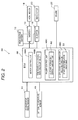
FIG. 1 is a block diagram illustrating an overall configuration of avehicle 10 on which acontrol apparatus 30 according to an embodiment of the present invention is installed. -
FIG. 2 is a functional block diagram illustrating a configuration of thecontrol apparatus 30. -
FIG. 3 is an explanatory graph of a temperature increase rate α. -
FIG. 4 is an explanatory graph of an electric powergeneration amount map 50 illustrating a relationship between the temperature increase rate α and electric power generation amount P (kW). -
FIG. 5 is an explanatory graph of a startdetermination value map 52 illustrating a relationship between a battery temperature TB and an engine start determination value α1. -
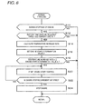
FIG. 6 is a flow chart illustrating operations of thecontrol apparatus 30. -
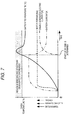
FIG. 7 is an explanatory graph illustrating a comparative example in which anengine 22 is started at the instant when the battery temperature TB reaches a given temperature Tu. -
FIG. 8 is an explanatory graph illustrating operations of thecontroller 30 performed when the temperature increase rate α is low and an amount of increase in the battery temperature TB after engine start is relatively low. -
FIG. 9 is an explanatory graph illustrating operations of thecontroller 30 performed when the temperature increase rate α is high and the amount of increase in the battery temperature TB after engine start is relatively high. - Hereinafter, an embodiment of the present invention will be described with reference to the drawings.
- As illustrated in
FIG. 1 , thevehicle 10 includes: ahigh voltage battery 12;inverters front motor 18 serving as an electric motor; arear motor 20 serving as an electric motor; anengine 22 serving as an internal combustion engine; agenerator 24;front wheels 26;rear wheels 28; and acontrol apparatus 30 according to the present invention. - Accordingly, the
vehicle 10 constitutes a hybrid electric vehicle on which themotors engine 22 are installed. - The
high voltage battery 12 supplies electric power to the front andrear motors high voltage battery 12 to the front andrear motors - The
high voltage battery 12 is charged with electric power supplied from, for example, a domestic commercial power supply or a quick-charging power supply of a charging station via unillustrated charging equipment. - Continuous supply of electric current to the motor(s) causes a gradual increase in temperature of the
high voltage battery 12 as a chemical change inside the battery proceeds. When a situation in which the temperature of the battery is excessively increased continues, degradation of the battery might occur. Note that when the battery temperature becomes equal to or higher than a preset temperature, thehigh voltage battery 12 is forcedly cooled by an unillustrated cooling fan; however, even when thehigh voltage battery 12 is forcedly cooled by the cooling fan, it is inevitable that the battery temperature will be excessively increased depending on level of the battery current, time period during which the battery current is supplied, and environmental temperature. - The
inverters high voltage battery 12, into three-phase AC electric power, and supply the three-phase AC electric power to the front andrear motors - Based on control performed by an
ECU 48 described later, the three-phase AC electric power, which is supplied to the front andrear motors inverters rear motors - The
front motor 18 is driven and rotated by the AC electric power supplied from theinverter 14, and provides power (driving torque) to thefront wheels 26 via aspeed reducer 32 and adifferential gear 34, thereby driving thefront wheels 26. - The
rear motor 20 is driven and rotated by the three-phase AC electric power supplied from theinverter 16, and provides power (driving torque) to therear wheels 28 via aspeed reducer 36 and adifferential gear 38, thereby driving therear wheels 28. - Furthermore, when regenerative braking of the
vehicle 10 is performed, the front andrear motors rear motors inverters high voltage battery 12 is charged with the DC electric power. - The
motors - The
motors motors - The lower the motor coil temperature, the larger the rush current, and the higher the motor coil temperature, the smaller the rush current.
- The
engine 22 is connected to thespeed reducer 32 via aspeed reducer 40 and aclutch 42. Engagement and disengagement of theclutch 42 is controlled by the ECU. - When the
clutch 42 is in a disengaged state, theengine 22 provides power to thegenerator 24 via aspeed reducer 41 and thus drives thegenerator 24. - The
generator 24 generates electric power by the power supplied from theengine 22, and charges thehigh voltage battery 12 via theinverter 14. - Note that in a state where the battery current is supplied to the front motor 18 (and/or the rear motor 20) from the
high voltage battery 12 and thus the front motor 18 (and/or the rear motor 20) are/is driven, theengine 22 is started to allow thegenerator 24 to generate electric power; then, the electric power (electric current) generated by thegenerator 24 is supplied to the front motor 18 (and/or the rear motor 20), and in addition, thehigh voltage battery 12 is charged with electric power (electric current) that has not been consumed by driving of the front motor 18 (and/or the rear motor 20). In other words, the electric current supplied from thegenerator 24 is added to the battery current supplied from thehigh voltage battery 12, and the resulting electric current is supplied to thefront motor 18 and/or therear motor 20. - Moreover, for the sake of simplification, the following description will be made on a case where the
vehicle 10 travels by using only thefront motor 18. However, the present invention is also naturally applicable to a case where thevehicle 10 travels by using only therear motor 20, or a case where thevehicle 10 travels by using both of the front andrear motors - Note that the present embodiment will be described on the assumption that when the
clutch 42 is in the disengaged state, theengine 22 provides power to thegenerator 24 via thespeed reducer 41 and thus drives thegenerator 24. - However, the present invention is also naturally applicable to a case where when the
clutch 42 is in the engaged state, theengine 22 provides power to thegenerator 24 via thespeed reducer 41 and thus drives thegenerator 24, while theengine 22 provides power (driving torque) to thefront wheels 26 via thespeed reducer 40, theclutch 42, the speed reducer 32 and thedifferential gear 34 and thus drives thefront wheels 26. - The
control apparatus 30 includes: anaccelerator pedal sensor 44; abattery temperature sensor 46; and theECU 48. - The
accelerator pedal sensor 44 detects an accelerator pedal pressing amount, and supplies the detected value to theECU 48. - The
battery temperature sensor 46 detects a temperature of the high voltage battery 12 (which will hereinafter be referred to as a "battery temperature TB"), and supplies the detected value to theECU 48. In the present embodiment, thebattery temperature sensor 46 constitutes a "temperature detector". - The
ECU 48 includes: a CPU; a ROM for storing/retaining a control program or the like; a RAM serving as an area where the control program is operated; and an interface section serving as an interface between theECU 48 and a peripheral circuit or the like. - As illustrated in
FIG. 2 , theECU 48 executes the control program, thereby implementing: amotor control unit 48A; a temperature increaserate calculating unit 48B; anengine control unit 48C; and an engine start determinationvalue setting unit 48D. Note that in the present embodiment, theengine control unit 48C and the engine start determinationvalue setting unit 48D constitute an "engine controller". - The
motor control unit 48A controls the electric current, supplied to thefront motor 18 from thehigh voltage battery 12, in accordance with the accelerator pedal pressing amount detected by theaccelerator pedal sensor 44, i.e., in accordance with the required driving torque. - The temperature increase
rate calculating unit 48B calculates, based on the battery temperature TB detected by thebattery temperature sensor 46, a temperature increase rate α that is an amount of increase in the battery temperature TB per unit time. - Specifically, as illustrated in
FIG. 3 , when the amount of increase in the battery temperature TB per unit time Δt is ΔTB, the temperature increase rate α is defined by ΔTB/Δt. - The
engine control unit 48C controls, for example, the start, stop and RPM of theengine 22. When the temperature increase rate α calculated by the temperature increaserate calculating unit 48B is equal to or higher than an engine start determination value α1 that is a preset threshold value, theengine control unit 48C starts theengine 22, thereby activating thegenerator 24. - In the present embodiment, the
engine control unit 48C controls theengine 22 so that the higher the temperature increase rate α, the larger the electric power generation amount of thegenerator 24 will be. In other words, theengine control unit 48C controls theengine 22 so that the higher the temperature increase rate α, the higher the RPM of theengine 22 will be. - In the present embodiment, the
engine control unit 48C includes an electric powergeneration amount map 50. - As illustrated in
FIG. 4 , the electric powergeneration amount map 50 is a map illustrating a relationship between the temperature increase rate α and electric power generation amount P (kW). - The
engine control unit 48C identifies the electric power generation amount P from the temperature increase rate α based on the electric powergeneration amount map 50, and controls the RPM of the engine 22 (or controls driving of the engine 22) so that the electric power generation amount P is generated by thegenerator 24. - Further, when the battery temperature TB detected by the
battery temperature sensor 46 is equal to or higher than a first threshold temperature TB1 (which is a first given temperature set in advance), theengine control unit 48C allows the start of theengine 22; on the other hand, when the detected battery temperature TB is below the first threshold temperature TB1, theengine control unit 48C disallows the start of theengine 22. - The first threshold temperature TB1 is set as a temperature at which no consideration has to be given to degradation of the
high voltage battery 12 because even if a pronounced temperature increase has occurred, the battery temperature TB is originally low as long as the battery temperature TB is below the first threshold temperature TB1. The first threshold temperature TB1 is set at room temperature (25°), for example. - Furthermore, the
engine control unit 48C stops theengine 22 upon satisfaction of an engine stop requirement after the start of theengine 22. - In the present embodiment, the engine stop requirement is that a period during which the battery temperature TB detected by the
battery temperature sensor 46 is continuously below a second threshold temperature TB2 (which is a second given temperature set in advance) must be equal to or longer than a threshold period (which is a given period set in advance) . The second threshold temperature TB2 is set as a temperature that allows degradation of thehigh voltage battery 12 to be ignored as long as the battery temperature TB is below the second threshold temperature TB2. Note that the engine stop requirement is not limited to this example but any requirement may be set. - The engine start determination
value setting unit 48D sets the engine start determination value α1 so that the higher the battery temperature TB detected by thebattery temperature sensor 46, the lower the engine start determination value α1 will be. - In the present embodiment, the engine start determination
value setting unit 48D includes a startdetermination value map 52. As illustrated inFIG. 5 , the startdetermination value map 52 is a map illustrating a relationship between the battery temperature TB and the engine start determination value α1. - The engine start determination
value setting unit 48D identifies and sets the engine start determination value α1 from the battery temperature TB based on the startdetermination value map 52. - Next, referring to a flow chart of
FIG. 6 , operations of thecontroller 30 will be described. - Processing illustrated in
FIG. 6 is carried out repeatedly when normal traveling of thevehicle 10 is performed by using themotor 18 with theengine 22 stopped. - First, the
ECU 48 determines whether or not theengine 22 is stopped (Step S10). - When the answer is NO in Step S10, the
ECU 48 skips the subsequent processes and returns the processing. - When the answer is YES in Step S10, the
ECU 48 determines whether or not the battery temperature TB detected by thebattery temperature sensor 46 is equal to or higher than the first threshold temperature TB1 (Step S12). - When the answer is NO in Step S12, the
ECU 48 skips the subsequent processes and returns the processing. When the answer is YES in Step S12, the ECU 48 (temperature increaserate calculating unit 48B) calculates the temperature increase rate α (Step S14). Specifically, the start of theengine 22 is disallowed when the battery temperature TB is below the first threshold temperature TB1, and the start of theengine 22 is allowed when the battery temperature TB is equal to or higher than the first threshold temperature TB1. - Subsequently, the ECU 48 (engine start determination
value setting unit 48D) identifies and sets the engine start determination value α1 from the battery temperature TB based on the start determination value map 52 (Step S16). - Then, the ECU 48 (
engine control unit 48C) determines whether or not the temperature increase rate α is equal to or higher than the engine start determination value α1 (Step S18) . - When the answer is No in Step S18, the
ECU 48 skips the subsequent processes and returns the processing. - When the answer is YES in Step S18, the ECU 48 (
engine control unit 48C) starts engine start control (Step S20). Specifically, theECU 48 identifies the electric power generation amount P from the temperature increase rate α based on the electric powergeneration amount map 50, and controls the RPM of theengine 22 so that the electric power generation amount P is generated by thegenerator 24. - Subsequently, the ECU 48 (
engine control unit 48C) determines whether or not the period during which the battery temperature TB is continuously below the second threshold temperature TB2 is equal to or longer than the preset threshold period (Step S22). - When the answer is NO in Step S22, the
ECU 48 returns the processing to Step S20 to continue to control theengine 22. - When the answer is YES in Step S22, the
ECU 48 stops theengine 22 and returns the processing. - The above processing is carried out repeatedly.
- Next, operations and effects of the present embodiment will be described with reference to
FIGS. 7 to 9 . - The following description will be made on the assumption that in a state where normal traveling of the
vehicle 10 is performed by using themotor 18 with theengine 22 stopped, the battery temperature TB is increased with the passage of time and then theengine 22 is started in the course of time. - In each of
FIGS. 7 to 9 , the horizontal axis represents time, and the vertical axis represents the battery temperature TB, battery current, electric current generated by theengine 22, and torque of themotor 18. - In each of
FIGS. 7 to 9 , the reference character "Tu" signifies a given temperature. When the battery temperature TB is equal to or higher than the given temperature Tu, the degree of degradation of the battery is increased. Accordingly, in order to suppress degradation of thehigh voltage battery 12, it is important to prevent the battery temperature TB from reaching a hatched battery degradation region where the battery temperature TB is equal to or higher than the given temperature Tu. - First, for the sake of clarity, a comparative example in which the
engine 22 is started at the instant when the battery temperature TB reaches the given temperature Tu will be described with reference toFIG. 7 . - When normal traveling is performed by using the
motor 18, the battery temperature TB will be increased with the passage of time. - In the course of time, when the battery temperature TB reaches the given temperature Tu, the
engine 22 is started to activate thegenerator 24, so that thegenerator 24 starts to generate electric power and the generated electric current is supplied to themotor 18. As the generated electric current supplied to themotor 18 is increased, the battery current supplied to themotor 18 from thehigh voltage battery 12 is reduced. In this case, motor torque is kept constant before and after the start of theengine 22. - Due to the reduction in the battery current, the battery temperature TB will be reduced with the passage of time.
- However, in this example, there is apprehension that the
high voltage battery 12 will be degraded because the battery temperature TB continues to increase for a while even after electric power generation is started by theengine 22 and the battery current is reduced, and the battery temperature TB stays within the hatched region and then drops. - On the other hand, in the present embodiment, the
engine 22 is started when the temperature increase rate α is equal to or higher than the engine start determination value α1. - Hence, when the temperature increase rate α is high and the battery temperature TB obviously tends to reach the battery degradation region, the
engine 22 is started at an earlier stage, thus making it possible to appropriately prevent the battery temperature TB from reaching the battery degradation region. - On the other hand, when the temperature increase rate α is low and the battery temperature TB slightly tends to reach the battery degradation region, the
engine 22 is prevented from being started at an early stage, thus making it possible to appropriately prevent the battery temperature TB from reaching the battery degradation region while suppressing a reduction in fuel efficiency. - Accordingly, the present invention is advantageous in terms of suppressing degradation of the
high voltage battery 12, caused by an excessive increase in the battery temperature TB, while suppressing a reduction in fuel efficiency. - Furthermore, in the present embodiment, the higher the battery temperature TB, the lower the engine start determination value α1 will be. In other words, the
engine 22 is started such that the higher the battery temperature TB, the lower the engine start determination value α1 will be. - Hence, when the battery temperature TB is high and the battery temperature TB obviously tends to reach the battery degradation region, the
engine 22 is started at an earlier stage, thus making it possible to appropriately prevent the battery temperature TB from reaching the battery degradation region. - On the other hand, when the battery temperature TB is low and the battery temperature TB slightly tends to reach the battery degradation region, the
engine 22 is prevented from being started at an early stage, thus making it possible to appropriately prevent the battery temperature TB from reaching the battery degradation region while suppressing a reduction in fuel efficiency. - Accordingly, the present invention is further advantageous in terms of suppressing degradation of the
high voltage battery 12, caused by an excessive increase in the battery temperature TB, while suppressing a reduction in fuel efficiency. - Moreover, in the present embodiment, as illustrated in
FIGS. 8 and9 , the driving of theengine 22 is controlled and the engine-generated electric current is increased so that the higher the temperature increase rate α, the larger the electric power generation amount P of thegenerator 24. - Specifically,
FIG. 8 illustrates a case where the temperature increase rate α is low and the amount of increase in the battery temperature TB after engine start is relatively small, andFIG. 9 illustrates a case where the temperature increase rate α is high and the amount of increase in the battery temperature TB after engine start is relatively large. - Accordingly, as illustrated in
FIG. 8 , when the temperature increase rate α is low, there is no need to ensure such a high engine-generated electric current; hence, it is possible to reduce the battery current while suppressing a reduction in fuel efficiency, and a reduction in the battery temperature TB is promoted, thus appropriately suppressing the amount of increase in the battery temperature TB after engine start. - On the other hand, as illustrated in
FIG. 9 , when the temperature increase rate α is high, a high engine-generated electric current can be ensured; hence, it is possible to further reduce the battery current and to further promote a reduction in the battery temperature TB, thus appropriately suppressing the amount of increase in the battery temperature TB after engine start. - Consequently, the present invention makes it possible to appropriately suppress the amount of increase in the battery temperature TB after engine start while suppressing a reduction in fuel efficiency, and is thus further advantageous in terms of suppressing degradation of the
high voltage battery 12. - Further, in the present embodiment, the start of the
engine 22 is allowed when the battery temperature TB is equal to or higher than the first threshold temperature TB1, and the start of theengine 22 is disallowed when the battery temperature TB is below the first threshold temperature TB1. - Accordingly, the present invention can suppress unnecessary start of the
engine 22, and is thus further advantageous in terms of suppressing degradation of thehigh voltage battery 12 while suppressing a reduction in fuel efficiency. - Furthermore, in the present embodiment, the
engine 22 is stopped when the period during which the battery temperature TB is continuously below the second threshold temperature TB2 after the start of theengine 22 is equal to or longer than the preset threshold period. - Accordingly, the present invention can appropriately stop the
engine 22 in accordance with a reduction in the battery temperature TB, and is thus further advantageous in terms of suppressing a reduction in fuel efficiency. - According to an aspect of the invention, the engine is started when the temperature increase rate is equal to or higher than the threshold value. Hence, when the temperature increase rate is high and the battery temperature obviously tends to reach a high temperature, the engine is started at an earlier stage; on the other hand, when the temperature increase rate is low and the battery temperature slightly tends to reach a high temperature, the engine is prevented from being started at an early stage. Accordingly, the present invention is advantageous in terms of suppressing degradation of the battery, caused by an excessive increase in the battery temperature, while suppressing a reduction in fuel efficiency. Further, the threshold value is set so that the higher the battery temperature, the lower the threshold value will be. Hence, when the battery temperature is high and the battery temperature obviously tends to reach a high temperature, the engine is started at an earlier stage; on the other hand, when the battery temperature is low and the battery temperature slightly tends to reach a battery degradation region, the engine is prevented from being started at an early stage. Consequently, the present invention is further advantageous in terms of suppressing degradation of the high voltage battery, caused by an excessive increase in the battery temperature, while suppressing a reduction in fuel efficiency.
- According to an aspect of the invention, the driving of the engine is controlled so that the higher the temperature increase rate, the larger the electric power generation amount of the generator will be. Hence, when the temperature increase rate is low, the battery current is reduced while a reduction in fuel efficiency is suppressed; on the other hand, when the temperature increase rate is high, the battery current is further reduced. Consequently, the present invention makes it possible to appropriately suppress the amount of increase in the battery temperature after engine start while suppressing a reduction in fuel efficiency, and is thus further advantageous in terms of suppressing degradation of the battery.
- According to an aspect of the invention, the start of the engine is allowed when the battery temperature is equal to or higher than the first threshold temperature, and the start of the engine is disallowed when the battery temperature is below the first threshold temperature. Consequently, the present invention can suppress unnecessary start of the engine, and is thus further advantageous in terms of suppressing degradation of the battery while suppressing a reduction in fuel efficiency.
- According to an aspect of the invention, the engine is stopped when the period during which the battery temperature is continuously below the second threshold temperature after the start of the engine is equal to or longer than the preset threshold period. Consequently, the present invention can appropriately stop the engine in accordance with a reduction in the battery temperature, and is thus further advantageous in terms of suppressing a reduction in fuel efficiency.
Claims (4)
- A control apparatus for a hybrid electric vehicle comprising: an electric motor configured to drive a driving wheel of the hybrid electric vehicle; a battery configured to supply an electric current to the electric motor; a generator configured to supply an electric current to the electric motor; and an engine configured to allow the generator to generate electric power, the control apparatus comprising:a temperature detector configured to detect a temperature of the battery;a temperature increase rate calculator configured to calculate, based on the detected temperature of the battery, a temperature increase rate that is an amount of increase in the temperature per unit time; andan engine controller configured to allow, when the temperature increase rate is equal to or higher than a threshold value, the engine to be started, so that the generator generates the electric power,wherein the threshold value is set so that the higher the detected battery temperature, the lower the threshold value.
- The control apparatus according to claim 1, wherein the engine controller controls the engine so that the higher the temperature increase rate, the larger an electric power generation amount of the generator.
- The control apparatus according to claim 1 or claim 2, wherein the engine controller allows start of the engine when the detected temperature of the battery is equal to or higher than a preset first temperature, and disallows start of the engine when the detected temperature of the battery is lower the first temperature.
- The control apparatus according to any one of claims 1 to 3, wherein the engine controller stops the engine when a period during which the detected temperature of the battery is continuously lower than a second preset temperature after start of the engine is equal to or longer than a preset period.
Applications Claiming Priority (1)
| Application Number | Priority Date | Filing Date | Title |
|---|---|---|---|
| JP2011195631A JP5742607B2 (en) | 2011-09-08 | 2011-09-08 | Control device for hybrid electric vehicle |
Publications (3)
| Publication Number | Publication Date |
|---|---|
| EP2567858A2 true EP2567858A2 (en) | 2013-03-13 |
| EP2567858A3 EP2567858A3 (en) | 2016-12-28 |
| EP2567858B1 EP2567858B1 (en) | 2020-07-15 |
Family
ID=47221097
Family Applications (1)
| Application Number | Title | Priority Date | Filing Date |
|---|---|---|---|
| EP12183561.5A Active EP2567858B1 (en) | 2011-09-08 | 2012-09-07 | Control apparatus for hybrid electric vehicle |
Country Status (4)
| Country | Link |
|---|---|
| US (1) | US9586574B2 (en) |
| EP (1) | EP2567858B1 (en) |
| JP (1) | JP5742607B2 (en) |
| CN (1) | CN103072484B (en) |
Families Citing this family (13)
| Publication number | Priority date | Publication date | Assignee | Title |
|---|---|---|---|---|
| JP5742607B2 (en) * | 2011-09-08 | 2015-07-01 | 三菱自動車工業株式会社 | Control device for hybrid electric vehicle |
| US8700243B2 (en) * | 2011-09-12 | 2014-04-15 | Toyota Jidosha Kabushiki Kaisha | Vehicle control device |
| DE102013221516A1 (en) * | 2013-10-23 | 2015-04-23 | Bayerische Motoren Werke Aktiengesellschaft | An air supply device for a vehicle seat and method for operating the air supply device |
| JP6427795B2 (en) * | 2014-11-27 | 2018-11-28 | 三菱自動車工業株式会社 | Hybrid electric vehicle |
| JP6443743B2 (en) * | 2014-12-25 | 2018-12-26 | 三菱自動車工業株式会社 | Electric vehicle |
| CN105172572B (en) * | 2015-08-05 | 2018-01-26 | 重庆长安汽车股份有限公司 | Four-wheel drive hybrid vehicle and its power drive system |
| CN105172573A (en) * | 2015-11-02 | 2015-12-23 | 重庆长安汽车股份有限公司 | Control system of four-wheel-drive hybrid vehicle, control method of four-wheel-drive hybrid vehicle and vehicle |
| JP6693407B2 (en) * | 2016-12-21 | 2020-05-13 | 三菱自動車工業株式会社 | Hybrid vehicle |
| CN107939562B (en) * | 2017-10-27 | 2019-11-22 | 宁波吉利罗佑发动机零部件有限公司 | A kind of engine fuel temperature control method and its system, automobile |
| JP6919550B2 (en) * | 2017-12-21 | 2021-08-18 | トヨタ自動車株式会社 | Electric vehicle and control method of electric vehicle |
| US11623631B2 (en) * | 2020-06-02 | 2023-04-11 | Toyota Motor Engineering & Manufacturing North America, Inc. | Control of hybrid vehicle engine start threshold in congested traffic conditions |
| CN113978444B (en) * | 2021-10-29 | 2023-06-16 | 东风汽车集团股份有限公司 | Control method and system for hybrid electric vehicle under extremely cold condition |
| US12613286B2 (en) | 2024-01-22 | 2026-04-28 | Garrett Transportation I Inc. | System and method for battery parameter recharacterization |
Citations (1)
| Publication number | Priority date | Publication date | Assignee | Title |
|---|---|---|---|---|
| JP3707206B2 (en) | 1997-06-18 | 2005-10-19 | 日産自動車株式会社 | Generator control device for hybrid vehicle |
Family Cites Families (34)
| Publication number | Priority date | Publication date | Assignee | Title |
|---|---|---|---|---|
| TW348325B (en) | 1996-01-26 | 1998-12-21 | Yamaha Motor Co Ltd | Method and apparatus for monitoring deterioration of a storage battery |
| JP3371691B2 (en) * | 1996-06-25 | 2003-01-27 | 日産自動車株式会社 | Hybrid vehicle power generation control device |
| JP2000278811A (en) * | 1999-03-26 | 2000-10-06 | Mitsubishi Motors Corp | Power generation control device for hybrid electric vehicle |
| US6214625B1 (en) | 1999-04-28 | 2001-04-10 | Coulter International Corp. | Composition and method for differentiation of basophils and eosinophils in blood |
| JP3832237B2 (en) * | 2000-09-22 | 2006-10-11 | 日産自動車株式会社 | Control device for hybrid vehicle |
| JP3766028B2 (en) * | 2001-04-04 | 2006-04-12 | 本田技研工業株式会社 | Control device for electric motor and control device for hybrid vehicle |
| JP2003199207A (en) * | 2001-12-26 | 2003-07-11 | Aisin Aw Co Ltd | Electric vehicle drive control device, electric vehicle drive control method, and program thereof |
| JP3952884B2 (en) * | 2002-07-19 | 2007-08-01 | トヨタ自動車株式会社 | Automotive control device |
| JP3771526B2 (en) * | 2002-10-21 | 2006-04-26 | 株式会社日立製作所 | Secondary battery evaluation method and power storage device |
| WO2005081395A1 (en) * | 2004-02-19 | 2005-09-01 | Toyota Jidosha Kabushiki Kaisha | Motor driving apparatus |
| JP3963180B2 (en) * | 2004-05-28 | 2007-08-22 | トヨタ自動車株式会社 | Hybrid vehicle and control method thereof |
| JP4005069B2 (en) * | 2004-09-03 | 2007-11-07 | 本田技研工業株式会社 | Control device for hybrid vehicle |
| US8217620B2 (en) * | 2005-03-31 | 2012-07-10 | Energycs Llc | Method and system for retrofitting a full hybrid to be a plug-in hybrid |
| JP4175371B2 (en) * | 2006-02-02 | 2008-11-05 | トヨタ自動車株式会社 | INTERNAL COMBUSTION ENGINE DEVICE, ITS CONTROL METHOD, AND POWER OUTPUT DEVICE |
| JP5314235B2 (en) * | 2006-03-07 | 2013-10-16 | プライムアースEvエナジー株式会社 | Secondary battery temperature control device, secondary battery heating system, and program |
| JP4811080B2 (en) * | 2006-03-28 | 2011-11-09 | トヨタ自動車株式会社 | COOLING SYSTEM, AUTOMOBILE MOUNTING THE SAME, AND COOLING SYSTEM CONTROL METHOD |
| JP4466595B2 (en) * | 2006-03-28 | 2010-05-26 | トヨタ自動車株式会社 | COOLING SYSTEM, AUTOMOBILE MOUNTING THE SAME, AND COOLING SYSTEM CONTROL METHOD |
| US7797089B2 (en) | 2006-03-30 | 2010-09-14 | Ford Global Technologies, Llc | System and method for managing a power source in a vehicle |
| JP4064428B2 (en) * | 2006-05-24 | 2008-03-19 | 本田技研工業株式会社 | Control device for internal combustion engine |
| JP4327823B2 (en) * | 2006-06-15 | 2009-09-09 | トヨタ自動車株式会社 | COOLING SYSTEM, AUTOMOBILE MOUNTING THE SAME, AND COOLING SYSTEM CONTROL METHOD |
| JP2008184077A (en) | 2007-01-31 | 2008-08-14 | Hitachi Ltd | Hybrid cruise control system |
| JP4703593B2 (en) * | 2007-03-23 | 2011-06-15 | 株式会社豊田中央研究所 | Secondary battery state estimation device |
| JP4915273B2 (en) * | 2007-04-25 | 2012-04-11 | トヨタ自動車株式会社 | Electrical device and method for controlling electrical device |
| WO2009060765A1 (en) * | 2007-11-05 | 2009-05-14 | Mitsubishi Fuso Truck And Bus Corporation | Exhaust gas purifier of hybrid electric car |
| JP5167786B2 (en) * | 2007-11-29 | 2013-03-21 | 日産自動車株式会社 | Control device for hybrid vehicle |
| US8063609B2 (en) * | 2008-07-24 | 2011-11-22 | General Electric Company | Method and system for extending life of a vehicle energy storage device |
| JP4816780B2 (en) * | 2009-09-11 | 2011-11-16 | 株式会社デンソー | On-vehicle charge / discharge control device and partial control device included therein |
| EP2308708B1 (en) * | 2009-09-16 | 2016-08-17 | swissauto powersport llc | Electric vehicle with range extension |
| DE102009057174A1 (en) * | 2009-12-05 | 2011-06-09 | Volkswagen Ag | Method and device for controlling hybrid functions in a motor vehicle |
| CN102725499B (en) * | 2010-09-22 | 2014-01-15 | 丰田自动车株式会社 | Control device for internal combustion engine and control method for internal combustion engine |
| CN102122735B (en) * | 2010-12-21 | 2013-07-17 | 奇瑞汽车股份有限公司 | Thermal management method, system and device of battery |
| JP5321757B2 (en) * | 2011-01-27 | 2013-10-23 | トヨタ自動車株式会社 | Storage device control device and control method |
| JP5742607B2 (en) * | 2011-09-08 | 2015-07-01 | 三菱自動車工業株式会社 | Control device for hybrid electric vehicle |
| US9910100B2 (en) * | 2014-12-19 | 2018-03-06 | Automotive Research & Testing Center | Battery characteristic determining device for a vehicle |
-
2011
- 2011-09-08 JP JP2011195631A patent/JP5742607B2/en not_active Expired - Fee Related
-
2012
- 2012-09-07 EP EP12183561.5A patent/EP2567858B1/en active Active
- 2012-09-07 CN CN201210330817.6A patent/CN103072484B/en not_active Expired - Fee Related
- 2012-09-07 US US13/606,960 patent/US9586574B2/en not_active Expired - Fee Related
Patent Citations (1)
| Publication number | Priority date | Publication date | Assignee | Title |
|---|---|---|---|---|
| JP3707206B2 (en) | 1997-06-18 | 2005-10-19 | 日産自動車株式会社 | Generator control device for hybrid vehicle |
Also Published As
| Publication number | Publication date |
|---|---|
| JP2013056606A (en) | 2013-03-28 |
| US9586574B2 (en) | 2017-03-07 |
| CN103072484B (en) | 2016-08-03 |
| JP5742607B2 (en) | 2015-07-01 |
| US20130066498A1 (en) | 2013-03-14 |
| EP2567858B1 (en) | 2020-07-15 |
| EP2567858A3 (en) | 2016-12-28 |
| CN103072484A (en) | 2013-05-01 |
Similar Documents
| Publication | Publication Date | Title |
|---|---|---|
| EP2567858B1 (en) | Control apparatus for hybrid electric vehicle | |
| EP2567845B1 (en) | Control apparatus for hybrid electric vehicle | |
| CN110061554B (en) | Secondary battery system, vehicle provided with same, and method for controlling storage battery | |
| KR102345863B1 (en) | Hybrid vehicle control method and control device | |
| US8639413B2 (en) | Vehicle power supply system and method for controlling the same | |
| JP6217289B2 (en) | Hybrid vehicle control device | |
| EP3725614B1 (en) | Method and device for controlling hybrid vehicle | |
| KR101807364B1 (en) | Vehicle driven by electric motor and control method for vehicle | |
| JP6969357B2 (en) | Vehicle hybrid system | |
| US20190016194A1 (en) | Auxiliary heating system | |
| US20120191281A1 (en) | Electric vehicle | |
| JP5182514B2 (en) | Control device for electric vehicle | |
| JP7351175B2 (en) | Hybrid vehicle charging control method and hybrid vehicle charging control device | |
| KR102406066B1 (en) | Control method for hybrid vehicle in case of motor-generator drive belt slipping | |
| JP2018052343A (en) | Control device for hybrid vehicle | |
| JP2016141356A (en) | Power supply device for automobile, and method for controlling the same | |
| US20160009272A1 (en) | Power-generation control device and power-generation control method for hybrid vehicle | |
| JP2006170128A (en) | Vehicle control apparatus and vehicle | |
| JP5906641B2 (en) | Vehicle drive control device | |
| KR101628486B1 (en) | Method for controlling of charge in hybrid vehicle | |
| JP2015182569A (en) | Hybrid vehicle and control method of hybrid vehicle | |
| EP2610995B1 (en) | Electric power generation control system for vehicle | |
| JP2024100194A (en) | vehicle | |
| TW201640766A (en) | Controlling module for suppressing DC link voltage regeneration of permanent magnet motor and controlling method thereof | |
| JP2013021812A (en) | Vehicle |
Legal Events
| Date | Code | Title | Description |
|---|---|---|---|
| PUAI | Public reference made under article 153(3) epc to a published international application that has entered the european phase |
Free format text: ORIGINAL CODE: 0009012 |
|
| 17P | Request for examination filed |
Effective date: 20120907 |
|
| AK | Designated contracting states |
Kind code of ref document: A2 Designated state(s): AL AT BE BG CH CY CZ DE DK EE ES FI FR GB GR HR HU IE IS IT LI LT LU LV MC MK MT NL NO PL PT RO RS SE SI SK SM TR |
|
| AX | Request for extension of the european patent |
Extension state: BA ME |
|
| PUAL | Search report despatched |
Free format text: ORIGINAL CODE: 0009013 |
|
| AK | Designated contracting states |
Kind code of ref document: A3 Designated state(s): AL AT BE BG CH CY CZ DE DK EE ES FI FR GB GR HR HU IE IS IT LI LT LU LV MC MK MT NL NO PL PT RO RS SE SI SK SM TR |
|
| AX | Request for extension of the european patent |
Extension state: BA ME |
|
| RIC1 | Information provided on ipc code assigned before grant |
Ipc: B60W 10/06 20060101ALI20161123BHEP Ipc: B60W 10/08 20060101ALI20161123BHEP Ipc: B60W 10/26 20060101ALI20161123BHEP Ipc: B60L 11/18 20060101AFI20161123BHEP Ipc: B60W 20/00 20160101ALI20161123BHEP |
|
| STAA | Information on the status of an ep patent application or granted ep patent |
Free format text: STATUS: EXAMINATION IS IN PROGRESS |
|
| 17Q | First examination report despatched |
Effective date: 20180801 |
|
| RAP1 | Party data changed (applicant data changed or rights of an application transferred) |
Owner name: MITSUBISHI JIDOSHA KOGYO KABUSHIKI KAISHA |
|
| REG | Reference to a national code |
Ref country code: DE Ref legal event code: R079 Ref document number: 602012071238 Country of ref document: DE Free format text: PREVIOUS MAIN CLASS: B60L0011180000 Ipc: B60L0058000000 |
|
| GRAP | Despatch of communication of intention to grant a patent |
Free format text: ORIGINAL CODE: EPIDOSNIGR1 |
|
| STAA | Information on the status of an ep patent application or granted ep patent |
Free format text: STATUS: GRANT OF PATENT IS INTENDED |
|
| RIC1 | Information provided on ipc code assigned before grant |
Ipc: B60W 10/26 20060101ALI20200211BHEP Ipc: B60W 10/08 20060101ALI20200211BHEP Ipc: B60L 58/00 20190101AFI20200211BHEP Ipc: B60L 58/25 20190101ALI20200211BHEP Ipc: B60W 20/00 20160101ALI20200211BHEP Ipc: B60W 10/06 20060101ALI20200211BHEP |
|
| INTG | Intention to grant announced |
Effective date: 20200306 |
|
| GRAS | Grant fee paid |
Free format text: ORIGINAL CODE: EPIDOSNIGR3 |
|
| GRAA | (expected) grant |
Free format text: ORIGINAL CODE: 0009210 |
|
| STAA | Information on the status of an ep patent application or granted ep patent |
Free format text: STATUS: THE PATENT HAS BEEN GRANTED |
|
| AK | Designated contracting states |
Kind code of ref document: B1 Designated state(s): AL AT BE BG CH CY CZ DE DK EE ES FI FR GB GR HR HU IE IS IT LI LT LU LV MC MK MT NL NO PL PT RO RS SE SI SK SM TR |
|
| REG | Reference to a national code |
Ref country code: CH Ref legal event code: EP Ref country code: GB Ref legal event code: FG4D |
|
| REG | Reference to a national code |
Ref country code: IE Ref legal event code: FG4D |
|
| REG | Reference to a national code |
Ref country code: DE Ref legal event code: R096 Ref document number: 602012071238 Country of ref document: DE |
|
| REG | Reference to a national code |
Ref country code: AT Ref legal event code: REF Ref document number: 1290657 Country of ref document: AT Kind code of ref document: T Effective date: 20200815 |
|
| REG | Reference to a national code |
Ref country code: LT Ref legal event code: MG4D |
|
| REG | Reference to a national code |
Ref country code: AT Ref legal event code: MK05 Ref document number: 1290657 Country of ref document: AT Kind code of ref document: T Effective date: 20200715 |
|
| REG | Reference to a national code |
Ref country code: NL Ref legal event code: MP Effective date: 20200715 |
|
| PG25 | Lapsed in a contracting state [announced via postgrant information from national office to epo] |
Ref country code: ES Free format text: LAPSE BECAUSE OF FAILURE TO SUBMIT A TRANSLATION OF THE DESCRIPTION OR TO PAY THE FEE WITHIN THE PRESCRIBED TIME-LIMIT Effective date: 20200715 Ref country code: NO Free format text: LAPSE BECAUSE OF FAILURE TO SUBMIT A TRANSLATION OF THE DESCRIPTION OR TO PAY THE FEE WITHIN THE PRESCRIBED TIME-LIMIT Effective date: 20201015 Ref country code: GR Free format text: LAPSE BECAUSE OF FAILURE TO SUBMIT A TRANSLATION OF THE DESCRIPTION OR TO PAY THE FEE WITHIN THE PRESCRIBED TIME-LIMIT Effective date: 20201016 Ref country code: SE Free format text: LAPSE BECAUSE OF FAILURE TO SUBMIT A TRANSLATION OF THE DESCRIPTION OR TO PAY THE FEE WITHIN THE PRESCRIBED TIME-LIMIT Effective date: 20200715 Ref country code: HR Free format text: LAPSE BECAUSE OF FAILURE TO SUBMIT A TRANSLATION OF THE DESCRIPTION OR TO PAY THE FEE WITHIN THE PRESCRIBED TIME-LIMIT Effective date: 20200715 Ref country code: FI Free format text: LAPSE BECAUSE OF FAILURE TO SUBMIT A TRANSLATION OF THE DESCRIPTION OR TO PAY THE FEE WITHIN THE PRESCRIBED TIME-LIMIT Effective date: 20200715 Ref country code: LT Free format text: LAPSE BECAUSE OF FAILURE TO SUBMIT A TRANSLATION OF THE DESCRIPTION OR TO PAY THE FEE WITHIN THE PRESCRIBED TIME-LIMIT Effective date: 20200715 Ref country code: BG Free format text: LAPSE BECAUSE OF FAILURE TO SUBMIT A TRANSLATION OF THE DESCRIPTION OR TO PAY THE FEE WITHIN THE PRESCRIBED TIME-LIMIT Effective date: 20201015 Ref country code: AT Free format text: LAPSE BECAUSE OF FAILURE TO SUBMIT A TRANSLATION OF THE DESCRIPTION OR TO PAY THE FEE WITHIN THE PRESCRIBED TIME-LIMIT Effective date: 20200715 Ref country code: PT Free format text: LAPSE BECAUSE OF FAILURE TO SUBMIT A TRANSLATION OF THE DESCRIPTION OR TO PAY THE FEE WITHIN THE PRESCRIBED TIME-LIMIT Effective date: 20201116 |
|
| PG25 | Lapsed in a contracting state [announced via postgrant information from national office to epo] |
Ref country code: PL Free format text: LAPSE BECAUSE OF FAILURE TO SUBMIT A TRANSLATION OF THE DESCRIPTION OR TO PAY THE FEE WITHIN THE PRESCRIBED TIME-LIMIT Effective date: 20200715 Ref country code: RS Free format text: LAPSE BECAUSE OF FAILURE TO SUBMIT A TRANSLATION OF THE DESCRIPTION OR TO PAY THE FEE WITHIN THE PRESCRIBED TIME-LIMIT Effective date: 20200715 Ref country code: LV Free format text: LAPSE BECAUSE OF FAILURE TO SUBMIT A TRANSLATION OF THE DESCRIPTION OR TO PAY THE FEE WITHIN THE PRESCRIBED TIME-LIMIT Effective date: 20200715 Ref country code: IS Free format text: LAPSE BECAUSE OF FAILURE TO SUBMIT A TRANSLATION OF THE DESCRIPTION OR TO PAY THE FEE WITHIN THE PRESCRIBED TIME-LIMIT Effective date: 20201115 |
|
| PG25 | Lapsed in a contracting state [announced via postgrant information from national office to epo] |
Ref country code: NL Free format text: LAPSE BECAUSE OF FAILURE TO SUBMIT A TRANSLATION OF THE DESCRIPTION OR TO PAY THE FEE WITHIN THE PRESCRIBED TIME-LIMIT Effective date: 20200715 |
|
| REG | Reference to a national code |
Ref country code: DE Ref legal event code: R097 Ref document number: 602012071238 Country of ref document: DE |
|
| PG25 | Lapsed in a contracting state [announced via postgrant information from national office to epo] |
Ref country code: MC Free format text: LAPSE BECAUSE OF FAILURE TO SUBMIT A TRANSLATION OF THE DESCRIPTION OR TO PAY THE FEE WITHIN THE PRESCRIBED TIME-LIMIT Effective date: 20200715 Ref country code: SM Free format text: LAPSE BECAUSE OF FAILURE TO SUBMIT A TRANSLATION OF THE DESCRIPTION OR TO PAY THE FEE WITHIN THE PRESCRIBED TIME-LIMIT Effective date: 20200715 Ref country code: RO Free format text: LAPSE BECAUSE OF FAILURE TO SUBMIT A TRANSLATION OF THE DESCRIPTION OR TO PAY THE FEE WITHIN THE PRESCRIBED TIME-LIMIT Effective date: 20200715 Ref country code: CZ Free format text: LAPSE BECAUSE OF FAILURE TO SUBMIT A TRANSLATION OF THE DESCRIPTION OR TO PAY THE FEE WITHIN THE PRESCRIBED TIME-LIMIT Effective date: 20200715 Ref country code: EE Free format text: LAPSE BECAUSE OF FAILURE TO SUBMIT A TRANSLATION OF THE DESCRIPTION OR TO PAY THE FEE WITHIN THE PRESCRIBED TIME-LIMIT Effective date: 20200715 Ref country code: DK Free format text: LAPSE BECAUSE OF FAILURE TO SUBMIT A TRANSLATION OF THE DESCRIPTION OR TO PAY THE FEE WITHIN THE PRESCRIBED TIME-LIMIT Effective date: 20200715 Ref country code: IT Free format text: LAPSE BECAUSE OF FAILURE TO SUBMIT A TRANSLATION OF THE DESCRIPTION OR TO PAY THE FEE WITHIN THE PRESCRIBED TIME-LIMIT Effective date: 20200715 |
|
| REG | Reference to a national code |
Ref country code: CH Ref legal event code: PL |
|
| PLBE | No opposition filed within time limit |
Free format text: ORIGINAL CODE: 0009261 |
|
| STAA | Information on the status of an ep patent application or granted ep patent |
Free format text: STATUS: NO OPPOSITION FILED WITHIN TIME LIMIT |
|
| PG25 | Lapsed in a contracting state [announced via postgrant information from national office to epo] |
Ref country code: AL Free format text: LAPSE BECAUSE OF FAILURE TO SUBMIT A TRANSLATION OF THE DESCRIPTION OR TO PAY THE FEE WITHIN THE PRESCRIBED TIME-LIMIT Effective date: 20200715 |
|
| REG | Reference to a national code |
Ref country code: BE Ref legal event code: MM Effective date: 20200930 |
|
| 26N | No opposition filed |
Effective date: 20210416 |
|
| GBPC | Gb: european patent ceased through non-payment of renewal fee |
Effective date: 20201015 |
|
| PG25 | Lapsed in a contracting state [announced via postgrant information from national office to epo] |
Ref country code: LU Free format text: LAPSE BECAUSE OF NON-PAYMENT OF DUE FEES Effective date: 20200907 Ref country code: SK Free format text: LAPSE BECAUSE OF FAILURE TO SUBMIT A TRANSLATION OF THE DESCRIPTION OR TO PAY THE FEE WITHIN THE PRESCRIBED TIME-LIMIT Effective date: 20200715 |
|
| PG25 | Lapsed in a contracting state [announced via postgrant information from national office to epo] |
Ref country code: SI Free format text: LAPSE BECAUSE OF FAILURE TO SUBMIT A TRANSLATION OF THE DESCRIPTION OR TO PAY THE FEE WITHIN THE PRESCRIBED TIME-LIMIT Effective date: 20200715 Ref country code: IE Free format text: LAPSE BECAUSE OF NON-PAYMENT OF DUE FEES Effective date: 20200907 Ref country code: GB Free format text: LAPSE BECAUSE OF NON-PAYMENT OF DUE FEES Effective date: 20201015 Ref country code: LI Free format text: LAPSE BECAUSE OF NON-PAYMENT OF DUE FEES Effective date: 20200930 Ref country code: CH Free format text: LAPSE BECAUSE OF NON-PAYMENT OF DUE FEES Effective date: 20200930 Ref country code: BE Free format text: LAPSE BECAUSE OF NON-PAYMENT OF DUE FEES Effective date: 20200930 |
|
| PG25 | Lapsed in a contracting state [announced via postgrant information from national office to epo] |
Ref country code: TR Free format text: LAPSE BECAUSE OF FAILURE TO SUBMIT A TRANSLATION OF THE DESCRIPTION OR TO PAY THE FEE WITHIN THE PRESCRIBED TIME-LIMIT Effective date: 20200715 Ref country code: MT Free format text: LAPSE BECAUSE OF FAILURE TO SUBMIT A TRANSLATION OF THE DESCRIPTION OR TO PAY THE FEE WITHIN THE PRESCRIBED TIME-LIMIT Effective date: 20200715 Ref country code: CY Free format text: LAPSE BECAUSE OF FAILURE TO SUBMIT A TRANSLATION OF THE DESCRIPTION OR TO PAY THE FEE WITHIN THE PRESCRIBED TIME-LIMIT Effective date: 20200715 |
|
| PG25 | Lapsed in a contracting state [announced via postgrant information from national office to epo] |
Ref country code: MK Free format text: LAPSE BECAUSE OF FAILURE TO SUBMIT A TRANSLATION OF THE DESCRIPTION OR TO PAY THE FEE WITHIN THE PRESCRIBED TIME-LIMIT Effective date: 20200715 |
|
| PGFP | Annual fee paid to national office [announced via postgrant information from national office to epo] |
Ref country code: FR Payment date: 20230808 Year of fee payment: 12 Ref country code: DE Payment date: 20230802 Year of fee payment: 12 |
|
| REG | Reference to a national code |
Ref country code: DE Ref legal event code: R119 Ref document number: 602012071238 Country of ref document: DE |
|
| PG25 | Lapsed in a contracting state [announced via postgrant information from national office to epo] |
Ref country code: DE Free format text: LAPSE BECAUSE OF NON-PAYMENT OF DUE FEES Effective date: 20250401 |
|
| PG25 | Lapsed in a contracting state [announced via postgrant information from national office to epo] |
Ref country code: FR Free format text: LAPSE BECAUSE OF NON-PAYMENT OF DUE FEES Effective date: 20240930 |