EP2567848A1 - Travel drive device for dump truck - Google Patents
Travel drive device for dump truck Download PDFInfo
- Publication number
- EP2567848A1 EP2567848A1 EP12183140A EP12183140A EP2567848A1 EP 2567848 A1 EP2567848 A1 EP 2567848A1 EP 12183140 A EP12183140 A EP 12183140A EP 12183140 A EP12183140 A EP 12183140A EP 2567848 A1 EP2567848 A1 EP 2567848A1
- Authority
- EP
- European Patent Office
- Prior art keywords
- brake
- retainer
- mounting cylinder
- hub
- wheel mounting
- Prior art date
- Legal status (The legal status is an assumption and is not a legal conclusion. Google has not performed a legal analysis and makes no representation as to the accuracy of the status listed.)
- Granted
Links
Images




Classifications
-
- B—PERFORMING OPERATIONS; TRANSPORTING
- B60—VEHICLES IN GENERAL
- B60K—ARRANGEMENT OR MOUNTING OF PROPULSION UNITS OR OF TRANSMISSIONS IN VEHICLES; ARRANGEMENT OR MOUNTING OF PLURAL DIVERSE PRIME-MOVERS IN VEHICLES; AUXILIARY DRIVES FOR VEHICLES; INSTRUMENTATION OR DASHBOARDS FOR VEHICLES; ARRANGEMENTS IN CONNECTION WITH COOLING, AIR INTAKE, GAS EXHAUST OR FUEL SUPPLY OF PROPULSION UNITS IN VEHICLES
- B60K17/00—Arrangement or mounting of transmissions in vehicles
- B60K17/04—Arrangement or mounting of transmissions in vehicles characterised by arrangement, location or kind of gearing
- B60K17/043—Transmission unit disposed in on near the vehicle wheel, or between the differential gear unit and the wheel
- B60K17/046—Transmission unit disposed in on near the vehicle wheel, or between the differential gear unit and the wheel with planetary gearing having orbital motion
-
- B—PERFORMING OPERATIONS; TRANSPORTING
- B60—VEHICLES IN GENERAL
- B60T—VEHICLE BRAKE CONTROL SYSTEMS OR PARTS THEREOF; BRAKE CONTROL SYSTEMS OR PARTS THEREOF, IN GENERAL; ARRANGEMENT OF BRAKING ELEMENTS ON VEHICLES IN GENERAL; PORTABLE DEVICES FOR PREVENTING UNWANTED MOVEMENT OF VEHICLES; VEHICLE MODIFICATIONS TO FACILITATE COOLING OF BRAKES
- B60T1/00—Arrangements of braking elements, i.e. of those parts where braking effect occurs specially for vehicles
- B60T1/02—Arrangements of braking elements, i.e. of those parts where braking effect occurs specially for vehicles acting by retarding wheels
- B60T1/06—Arrangements of braking elements, i.e. of those parts where braking effect occurs specially for vehicles acting by retarding wheels acting otherwise than on tread, e.g. employing rim, drum, disc, or transmission or on double wheels
- B60T1/062—Arrangements of braking elements, i.e. of those parts where braking effect occurs specially for vehicles acting by retarding wheels acting otherwise than on tread, e.g. employing rim, drum, disc, or transmission or on double wheels acting on transmission parts
-
- F—MECHANICAL ENGINEERING; LIGHTING; HEATING; WEAPONS; BLASTING
- F16—ENGINEERING ELEMENTS AND UNITS; GENERAL MEASURES FOR PRODUCING AND MAINTAINING EFFECTIVE FUNCTIONING OF MACHINES OR INSTALLATIONS; THERMAL INSULATION IN GENERAL
- F16D—COUPLINGS FOR TRANSMITTING ROTATION; CLUTCHES; BRAKES
- F16D55/00—Brakes with substantially-radial braking surfaces pressed together in axial direction, e.g. disc brakes
- F16D55/24—Brakes with substantially-radial braking surfaces pressed together in axial direction, e.g. disc brakes with a plurality of axially-movable discs, lamellae, or pads, pressed from one side towards an axially-located member
- F16D55/26—Brakes with substantially-radial braking surfaces pressed together in axial direction, e.g. disc brakes with a plurality of axially-movable discs, lamellae, or pads, pressed from one side towards an axially-located member without self-tightening action
- F16D55/36—Brakes with a plurality of rotating discs all lying side by side
- F16D55/40—Brakes with a plurality of rotating discs all lying side by side actuated by a fluid-pressure device arranged in or one the brake
-
- F—MECHANICAL ENGINEERING; LIGHTING; HEATING; WEAPONS; BLASTING
- F16—ENGINEERING ELEMENTS AND UNITS; GENERAL MEASURES FOR PRODUCING AND MAINTAINING EFFECTIVE FUNCTIONING OF MACHINES OR INSTALLATIONS; THERMAL INSULATION IN GENERAL
- F16D—COUPLINGS FOR TRANSMITTING ROTATION; CLUTCHES; BRAKES
- F16D65/00—Parts or details
- F16D65/0031—Devices for retaining friction material debris, e.g. dust collectors or filters
-
- F—MECHANICAL ENGINEERING; LIGHTING; HEATING; WEAPONS; BLASTING
- F16—ENGINEERING ELEMENTS AND UNITS; GENERAL MEASURES FOR PRODUCING AND MAINTAINING EFFECTIVE FUNCTIONING OF MACHINES OR INSTALLATIONS; THERMAL INSULATION IN GENERAL
- F16D—COUPLINGS FOR TRANSMITTING ROTATION; CLUTCHES; BRAKES
- F16D65/00—Parts or details
- F16D65/78—Features relating to cooling
- F16D65/84—Features relating to cooling for disc brakes
- F16D65/853—Features relating to cooling for disc brakes with closed cooling system
-
- F—MECHANICAL ENGINEERING; LIGHTING; HEATING; WEAPONS; BLASTING
- F16—ENGINEERING ELEMENTS AND UNITS; GENERAL MEASURES FOR PRODUCING AND MAINTAINING EFFECTIVE FUNCTIONING OF MACHINES OR INSTALLATIONS; THERMAL INSULATION IN GENERAL
- F16D—COUPLINGS FOR TRANSMITTING ROTATION; CLUTCHES; BRAKES
- F16D2121/00—Type of actuator operation force
- F16D2121/02—Fluid pressure
- F16D2121/04—Fluid pressure acting on a piston-type actuator, e.g. for liquid pressure
Definitions
- the present invention relates to a travel drive device for a dump truck which is suitably used in transporting crushed stones excavated from such as an open-pit stope, a stone quarry, a mine or the like.
- a large-sized transporter vehicle called a dump truck has a liftable vessel (loading platform) on a frame of a vehicle body, and transports crushed stones or the like in a state of a heavy baggage being loaded in a large quantity on the vessel.
- a liftable vessel loading platform
- the characteristic of the construction adopted in the present invention comprises a foreign-object trapping portion is provided between the wheel support bearing and the seal mechanism for trapping foreign objects flowing from the seal mechanism toward the wheel support bearing.
- a travel drive device for a dump truck comprises a brake hub provided in the wheel mounting cylinder and forming a part of the wet brake to transmit a braking force of the wet brake to the wheel mounting cylinder; and a retainer provided between the axle housing and an inner race of the wheel support bearing and opposing the brake hub through an axial gap to be axially spaced therefrom, wherein: the foreign-object trapping portion is formed as a radial gap which provides a radial space between the brake hub and the retainer in a state of being communicated with the axial gap and is smaller than the axial gap.
- the retainer opposing the brake hub through the axial gap can form the radial gap of a dimension, which is smaller than that of the axial gap, between the retainer and the brake hub to trap the foreign object within the radial gap.
- the retainer is provided with an annular thickened portion on a surface radially opposing the brake hub, wherein the radial gap is formed by the annular thickened portion. Therefore, the process of making the radial gap between the brake hub and the annular thickened portion as small as possible can be relatively easily executed. That is, the foreign-object trapping portion can be formed in a simple process to improve the foreign-object trapping function.
- the cab 5 is provided in the front portion of the vehicle body 2 to be positioned under the protector 3A.
- the cab 5 forms an operator's room which the operator of the dump truck 1 gets in and off.
- An operator's seat, an activation switch, an accelerator pedal, a brake pedal, a handle for steering, and a plurality of operating levers (any of them is not shown) are provided inside of the cab 5.
- the protector 3A of the vessel 3 has functions of protecting the cab 5 from flying stones such as rocks by substantially completely covering the cab 5 from the upper side, and protecting the operator inside the cab 5 at the falling-down of a vehicle (dump truck 1).
- the spindles 14 are provided respectively at axial both sides of the axle housing 12 and each spindle 14 is formed in a cylindrical body.
- the spindle 14 is formed of a large-diameter cylindrical portion 14A positioned at an axial one side, formed to be tapered and removably fixed to the suspension tube 13 through bolts 15, and a circular cylindrical portion 14B formed integrally with the axial other side of the large-diameter cylindrical portion 14A.
- the circular cylindrical portion 14B is arranged to axially extend within the wheel mounting cylinder 18 to be described later.
- An outer peripheral side of the circular cylindrical portion 14B rotatably supports the wheel mounting cylinder 18 in the side of the rear wheel 7 through wheel support bearings 20 and 21 to be described later.
- the internal gear 35 and an outer drum 22 to be described later are integrally fixed to the extending cylindrical portion 18B of the wheel mounting cylinder 18 by using long bolts 23. Therefore, the wheel mounting cylinder 18 is rotated integrally with the internal gear 35. That is, rotation of large torque obtained by decelerating the rotation of the wheel drive motor 16 with the reduction gear mechanism 24 is transmitted to the wheel mounting cylinder 18 through the internal gear 35. Therefore, the wheel mounting cylinder 18 rotates the rear wheel 7 as the drive wheel in a vehicle with the large rotational torque.
- the reduction gear mechanism 24 is constituted by a first-stage planetary gear reduction mechanism 25 and a second-stage planetary gear reduction mechanism 33 to be described later.
- the reduction gear mechanism 24 decelerates rotation of the wheel drive motor 16 (that is, rotational shaft 17), which is transmitted to the wheel mounting cylinder 18 at the side of the rear wheel 7. Therefore, the wheel mounting cylinder 18 at the side of the rear wheel 7 is driven and rotated together with the rear wheel 7 by a large rotational force (torque) obtained by the deceleration.
- the lubricating system is constituted by including a partition wall 39, a suction pipe 40, a supply pipe 41, an inner retainer 42, an outer retainer 43, a shaft bearing 44 and the like.
- Denoted at 42 is the inner retainer provided to fit into an axial intermediate section of the rotational shaft 17 and denoted at 43 is an outer retainer located at the outer peripheral side of the inner retainer 42 through the shaft bearing 44.
- the inner retainer 42 is press-fitted at its inner peripheral side into the intermediate section of the rotational shaft 17 to rotate integrally with the rotational shaft 17.
- the outer retainer 43 is fixed to an inward projecting portion 14F of the spindle 14 by using bolts or the like. As shown in Fig. 3 , mid-sections of the suction pipe 40 and the supply pipe 41 extend to axially penetrate through the outer retainer 43, so that the suction pipe 40 and the supply pipe 41 are positioned in the spindle 14 through the outer retainer 43.
- the brake movable body 47 presses the respective non-rotating discs 49 in such a manner as to sandwich the respective rotating discs 48 at both sides therebetween, thus applying braking forces to the brake hub 51 rotating integrally with the wheel mounting cylinder 18.
- the brake movable body 47 is returned back by the urging spring, and the braking force to the brake hub 51 is released.
- the cooling liquid 50 is accommodated in the wet brake 45.
- the respective rotating discs 48 and the respective non-rotating discs 49 are immersed in the cooling liquid 50 to be cooled, thereby releasing the frictional heat generated at braking.
- the cooling liquid 50 is made up of an oil liquid different kind from the lubricant oil 100.
- the floating seal 53 to be described later has a function of preventing the cooling liquid 50 from leaking from a boundary between the end plate 46A of the brake housing 46 and the brake hub 51 to an outside.
- the floating seal 55 to be described later is provided between the retainer 54 to be described later and the brake hub 51 and has a function of separating the lubricant oil 100 from the cooling liquid 50 and keeping them in a sealed state.
- Denoted at 53 is the floating seal for leakage prevention for preventing the cooling liquid 50 of the wet brake 45 from leaking to an outside.
- the floating seal 53 is provided between the end plate 46A of the brake housing 46 and the brake-side O-ring receiving portion 51A of the brake hub 51 to prevent the cooling liquid 50 from leaking from a gap therebetween to an outside.
- the floating seal 53 also has a function of preventing foreign objects such as earth and sand, rain water, and the like from entering into the wet brake 45.
- Denoted at 54 is the retainer for positioning an inner race of the wheel support bearing 20 to the circular cylindrical portion 14B of the spindle 14, and the retainer 54 is provided to be fitted into the outer peripheral surface of the circular cylindrical portion 14B.
- An axial one side of the retainer 54 abuts against the annular step portion 14D of the spindle 14.
- An axial other side of the retainer 54 axially abuts against the inner race of the wheel support bearing 20. Therefore, in the wheel support bearing 20, the outer race is axially positioned by the hollow cylindrical portion 18A of the wheel mounting cylinder 18 and the inner race is axially positioned by the retainer 54.
- the travel drive device 11 for the dump truck 1 has the aforementioned configuration, and next, an operation thereof will be explained.
- the lubricant oil 100 reserved in the wheel mounting cylinder 18 is stirred upwards in order by rotation of the wheel mounting cylinder 18, the respective planetary gears 28 and 36 in the first and second-stage planetary gear reduction mechanisms 25 and 33, and the like. Therefore, the lubricant oil 100 is supplied to meshing sections of the respective gears, the wheel support bearings 20 and 21 between the circular cylindrical portion 14B of the spindle 14 and the wheel mounting cylinder 18, and the like. Thereafter, the lubricant oil 100 flows downwards and is reserved in the bottom side of the wheel mounting cylinder 18.
- the dump truck 1 can not be sufficiently decelerated simply by decelerating rotation of the wheel drive motor 16.
- an operator of the dump truck 1 depresses the brake pedal to supply a brake pressure (pressurized oil) to the wet brake 45 of a wet multi-plate type, thus driving the brake movable body 47 against the urging spring.
- the brake movable body 47 presses the respective non-rotating discs 49 in such a manner as to sandwich the respective rotating discs 48 from both sides and can apply braking forces to the brake hub 51 rotating integrally with the wheel mounting cylinder 18.
- the rotation of the rear wheel 7 is decelerated together with the wheel mounting cylinder 18, and the dump truck 1 can obtain a desired deceleration effect.
- the foreign-object trapping portion 58 can trap these broken pieces as foreign objects. Therefore, even if the axial gap T is communicated with the radial gap R, the foreign-object trapping portion 58 can prevent the foreign object from flowing from the wet brake 45 to the wheel support bearing 20 side. That is, the foreign-object trapping portion 58 can trap the foreign object to prevent the foreign object from reaching to the positions of the wheel support bearings 20 and 21 and the reduction gear mechanism 24 which are provided between the spindle 14 and the wheel mounting cylinder 18.
- the radial gap R1 between the hub-side O-ring receiving portion 51B of the brake hub 51 and the annular thickened portion 61D is formed to be smaller dimension than the axial gap T between the hub-side O-ring receiving portion 51B and the retainer-side O-ring receiving portion 54B (R1 ⁇ T).
- the cylindrical projecting portion 61C of the retainer 61 and the annular thickened portion 61D can form the foreign-object trapping portion 62 for trapping foreign objects between the hub-side O-ring receiving portion 51B of the brake hub 51 and the annular thickened portion 61D. Therefore, the second embodiment can obtain substantially the same functions and effects as in the first embodiment.
Landscapes
- Engineering & Computer Science (AREA)
- General Engineering & Computer Science (AREA)
- Mechanical Engineering (AREA)
- Transportation (AREA)
- Chemical & Material Sciences (AREA)
- Combustion & Propulsion (AREA)
- Arrangement Or Mounting Of Propulsion Units For Vehicles (AREA)
- General Details Of Gearings (AREA)
- Braking Arrangements (AREA)
Description
- The present invention relates to a travel drive device for a dump truck which is suitably used in transporting crushed stones excavated from such as an open-pit stope, a stone quarry, a mine or the like.
- In general, a large-sized transporter vehicle called a dump truck has a liftable vessel (loading platform) on a frame of a vehicle body, and transports crushed stones or the like in a state of a heavy baggage being loaded in a large quantity on the vessel.
- Therefore, each travel drive device for driving drive wheels of the dump truck for traveling is provided with a cylindrical axle housing mounted in a non-rotating state on a vehicle body, a rotational shaft provided to axially extend in the axle housing and driven by a drive source such as an electric motor for rotation, a wheel mounting cylinder which is rotatably mounted on an end-side periphery of the axle housing through bearings and to which vehicle wheels are mounted, and a reduction gear mechanism provided between the wheel mounting cylinder and the axle housing to decelerate rotation of the rotational shaft, which is transmitted to the wheel mounting cylinder (
Patent Documents 1 and 2). - A wet brake formed of a wet multi-plate type of hydraulic brake for applying a braking force to the rotation of the wheel mounting cylinder and a floating seal arranged between the wet brake and the bearings for retaining a cooling liquid of the wet brake in a sealed state to the wheel mounting cylinder are provided between the axle housing and the wheel mounting cylinder.
-
- Patent Document 1: Japanese Patent Laid-Open No.
2009-204016 A - Patent Document 2: Japanese Patent Laid-Open No.
2010-116963 A - Incidentally, since a rotational load of large toque is acted to the travel drive device for the dump truck according to the aforementioned conventional art, lubricant oil is supplied to the bearings and the reduction gear mechanism provided between the axle housing and the wheel mounting cylinder. For isolating the lubricant oil from the cooling liquid in the wet brake side, a floating seal is disposed between the bearings and the wet brake.
- However, for example, when a braking operation of applying a braking force by operating the wet brake or releasing the braking force is repeatedly performed in the middle of traveling on a long down-slope, a heat generated amount of the wet brake increases to exceed a capability of the cooling liquid, possibly causing overheating. In the worst case, components of the wet brake are possibly broken or damaged. Further, a metallic seal ring in the floating seal is possibly broken or damaged due to generation of seizing, wear or the like on a sliding surface thereof under such a high-temperature condition. An O-ring of the floating seal is also possibly broken or damaged under an influence of a high temperature or a pressure from the wet brake.
- In such a case, there is a possibility that not only a sealing function of the floating seal is lost, but also broken pieces due to breakage and damage of the components from the wet brake and the floating seal enter into an inside of the wheel mounting cylinder as foreign objects and reach to positions of the bearings and the reduction gear mechanism provided between the axle housing and the wheel mounting cylinder. When the component in the reduction gear mechanism is damaged by the foreign object, in the worst case, the dump truck is difficult to drive and travel on its own. Particularly, since the dump truck as a large-sized transporter vehicle is difficult to be trailed by another vehicle, which is different from a general passenger car, it is desirable that the dump truck can travel to a safe place on its own in the meantime.
- In view of the above-discussed problem with the conventional art, it is an object of the present invention to provide a travel drive device for a dump truck which can protect a reduction gear mechanism and the like in a wheel mounting cylinder from foreign objects of a wet brake side to enhance durability and reliability of an entiredevice.
- (1) In order to solve the aforementioned problem, the present invention is applied to a travel drive device for a dump truck comprising a cylindrical axle housing mounted in a non-rotating state on a vehicle body of a dump truck; a rotational shaft provided to axially extend in the axle housing and driven and rotated by a drive source; a wheel mounting cylinder which is rotatably provided on an outer peripheral side of the axle housing through wheel support bearings and to which wheels are mounted; a reduction gear mechanism provided between the axle housing and the wheel mounting cylinder to decelerate rotation of the rotational shaft, which is transmitted to the wheel mounting cylinder; a wet brake provided between the axle housing and the wheel mounting cylinder for applying a braking force to rotation of the wheel mounting cylinder; and/or a seal mechanism positioned between the wet brake and the wheel support bearing and provided between the axle housing and the wheel mounting cylinder for keeping a cooling liquid of the wet brake in a sealed state to a lubricant oil in the wheel mounting cylinder.
- The characteristic of the construction adopted in the present invention comprises a foreign-object trapping portion is provided between the wheel support bearing and the seal mechanism for trapping foreign objects flowing from the seal mechanism toward the wheel support bearing.
- With this arrangement, even if the foreign object generated in the wet brake or the seal mechanism flows from the wet brake toward the wheel support bearing, the foreign object can be trapped by the foreign-object trapping portion provided in the outer peripheral side of the axle housing. Therefore, this arrangement can prevent the foreign object from reaching to positions of the wheel support bearing and the reduction gear mechanism provided between the axle housing and the wheel mounting cylinder. Since the components in the reduction gear mechanism can be protected from the foreign object in this manner, the dump truck as a large-sized transporter vehicle can drive and travel to a safe place on its own in the meantime.
- (2) According to the present invention, the foreign-object trapping portion is configured as a radial gap formed of a gap providing a radial space between a brake hub forming part of the wet brake and a retainer positioning an inner race of the wheel support bearing to the axle housing. With this configuration, the foreign object can be trapped in the radial gap formed between the brake hub and the retainer to prevent the foreign object from flowing in the downstream side.
- (3) According to the present invention, a travel drive device for a dump truck comprises a brake hub provided in the wheel mounting cylinder and forming a part of the wet brake to transmit a braking force of the wet brake to the wheel mounting cylinder; and a retainer provided between the axle housing and an inner race of the wheel support bearing and opposing the brake hub through an axial gap to be axially spaced therefrom, wherein: the foreign-object trapping portion is formed as a radial gap which provides a radial space between the brake hub and the retainer in a state of being communicated with the axial gap and is smaller than the axial gap. With this arrangement, the retainer opposing the brake hub through the axial gap can form the radial gap of a dimension, which is smaller than that of the axial gap, between the retainer and the brake hub to trap the foreign object within the radial gap.
- (4) According to the present invention, a travel drive device for a dump truck comprises a brake hub provided in the wheel mounting cylinder and forming a part of the wet brake to transmit a braking force of the wet brake to the wheel mounting cylinder; and a retainer provided between the axle housing and an inner race of the wheel support bearing and opposing the brake hub through an axial gap to be axially spaced therefrom, wherein: the seal mechanism comprises a floating seal formed by including a pair of seal rings and a pair of O-rings to seal the axial gap between the brake hub and the retainer; the brake hub is provided with a hub-side O-ring receiving portion axially extending toward the retainer to receive one O-ring in the floating seal; the retainer is provided with a retainer-side O-ring receiving portion axially opposing the hub-side O-ring receiving portion through the axial gap to receive other O-ring in the floating seal, and a cylindrical projecting portion formed to axially extend to a radial outer position than the retainer-side O-ring receiving portion and radially opposing the hub-side O-ring receiving portion; and the foreign-object trapping portion is formed as a radial gap which provides a radial space between the hub-side O-ring receiving portion and the cylindrical projecting portion in a state of being communicated with the axial gap and is smaller than the axial gap.
- According to the above arrangement, the foreign-object trapping portion may be configured as the radial gap which provides a radial space between the hub-side O-ring receiving portion provided in the brake hub and the cylindrical projecting portion in the retainer. Therefore, the foreign-object trapping portion is configured such that the radial gap is radially curved in an L-letter shape to the axial gap of the floating seal. Accordingly, even in a case where the foreign object passes through the axial gap between the brake hub and the retainer, the foreign object can be trapped by the foreign-object trapping portion formed to be curved in an L-letter shape to prevent the foreign object from flowing to the downstream side.
- (5) According to the present invention, the retainer is provided with an annular thickened portion on a surface radially opposing the brake hub, wherein the radial gap is formed by the annular thickened portion. Therefore, the process of making the radial gap between the brake hub and the annular thickened portion as small as possible can be relatively easily executed. That is, the foreign-object trapping portion can be formed in a simple process to improve the foreign-object trapping function.
-
-
Fig. 1 is a side view showing a dump truck to which a travel drive device according to a first embodiment of the present invention is applied. -
Fig. 2 is a rear view showing the dump truck inFig. 1 as viewed from the backside. -
Fig. 3 is an enlarged cross-sectional view showing the travel drive device in the rear wheel side, taken in the direction of the arrows III-III inFig. 1 . -
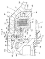
Fig. 4 is an enlarged cross-sectional view showing a wet brake, a brake hub, a retainer, a floating seal and the like inFig. 3 . -
Fig. 5 is a further enlarged cross -sectional view showing the brake hub, the retainer, the floating seal and the like inFig. 4 . -
Fig. 6 is an enlarged cross-sectional view showing a brake hub, a retainer, a floating seal and the like according to a second embodiment. - Hereinafter, a travel drive device for a dump truck according to embodiments of the present invention will be in detail explained with reference to the accompanying drawings, by taking a dump truck of a rear-wheel drive type as an example.
-
Fig. 1 to Fig. 5 show a travel drive device for a dump truck according to a first embodiment of the present invention. - In the figure, designated at 1 is a dump truck adopted in the first embodiment. As shown in
Fig. 1 , thedump truck 1 is constituted by including avehicle body 2 having a strong frame structure and avessel 3 as a loading platform liftably mounted on thevehicle body 2. - The
vessel 3 is formed as a large-sized container of an entire length of 10 to 13 meters for loading a large volume of heavy baggage such as crushed stones. A rear-side bottom portion of thevessel 3 is liftably (tiltably) connected to a rear end side of thevehicle body 2 through a connectingpin 4. Aprotector 3A is integrally provided in a front-side top portion of thevessel 3 in such a manner as to cover a cab 5 to be described later from the upper side. - The cab 5 is provided in the front portion of the
vehicle body 2 to be positioned under theprotector 3A. The cab 5 forms an operator's room which the operator of thedump truck 1 gets in and off. An operator's seat, an activation switch, an accelerator pedal, a brake pedal, a handle for steering, and a plurality of operating levers (any of them is not shown) are provided inside of the cab 5. Theprotector 3A of thevessel 3 has functions of protecting the cab 5 from flying stones such as rocks by substantially completely covering the cab 5 from the upper side, and protecting the operator inside the cab 5 at the falling-down of a vehicle (dump truck 1). - Left and right
front wheels 6 are rotatably provided on the front side of thevehicle body 2. Eachfront wheel 6 forms a steered wheel which is steered by an operator of thedump truck 1. Further, thefront wheel 6 is formed in a tire diameter (that is, outer diameter dimension), for example, as long as 2 to 4 meters in the same way as each ofrear wheels 7 to be described later. A front-wheel side suspension 6SP formed by a hydraulic shock absorber is provided between the front portion of thevehicle body 2 and thefront wheel 6. - The left and right
rear wheels 7 are rotatably provided on the rear side of thevehicle body 2. Eachrear wheel 7 forms a drive wheel of thedump truck 1 which is driven and rotated integrally with awheel mounting cylinder 18 by atravel drive device 11 to be described later as shown inFig. 3 . Eachrear wheel 7 is constituted by including dual tires of aninner tire 7A and anouter tire 7A, andrims 7B disposed in a radial inside of therespective tires 7A. A rear-wheel side suspension 7SP formed by a hydraulic shock absorber is provided between the rear portion of thevehicle body 2 and therear wheel 7. - An
engine 8 is provided in thevehicle body 2 to be positioned under the cab 5. Theengine 8 is constituted by, for example, a large-sized diesel engine and drives an on-board power generator and a hydraulic pump as a hydraulic source (any thereof is not shown) for rotation. Pressurized oil discharged from the hydraulic pump is supplied to hoistcylinders 9, a steering cylinder for power steering (not shown) and the like. - The hoist
cylinder 9 is a cylinder apparatus for lifting thevessel 3. As shown inFig. 1 , the hoistcylinder 9 is positioned between thefront wheel 6 and therear wheel 7 to be disposed in each of both left and right sides of thevehicle body 2. Each of the hoistcylinders 9 is mounted between thevehicle body 2 and thevessel 3 to telescopically operate in the upper-lower direction. Each of the hoistcylinders 9 expands and contracts in the upper-lower direction by supply/discharge of the pressurized oil from/to the hydraulic pump to lift (tilt) thevessel 3 around the connectingpin 4 of the rear side. - As shown in
Fig. 1 , an operatingoil tank 10 is mounted to a side of thevehicle body 2 or the like to be positioned under thevessel 3. Operating oil accommodated in the operatingoil tank 10 is suctioned by the hydraulic pump and discharged therefrom to be pressurized oil, which is supplied/discharged to/from the hoistcylinder 9, the steering cylinder for power steering, and the like. - Next, an explanation will be made of each of the
travel drive devices 11 which are provided to the side of therear wheel 7 in thedump truck 1 and form a key part of the first embodiment. - The
travel drive device 11 is constituted by including anaxle housing 12, awheel drive motor 16, awheel mounting cylinder 18 and areduction gear mechanism 24, which will be described later. Thetravel drive device 11 decelerates rotation of thewheel drive motor 16 by thereduction gear mechanism 24 and drives therear wheel 7 as drive wheel of vehicle together with thewheel mounting cylinder 18 by large rotational torque for traveling. - Denoted at 12 is the axle housing for the
rear wheel 7, which is provided under the rear side of thevehicle body 2 and theaxle housing 12 is formed in a cylindrical body which axially extends between the left and rightrear wheels 7. Theaxle housing 12 is constituted by anintermediate suspension tube 13 mounted to the rear side of thevehicle body 2 through the rear-wheel side suspension 7SP and aspindle 14 mounted to each of both left and right sides of thesuspension tube 13, which will be described later. - The
spindles 14 are provided respectively at axial both sides of theaxle housing 12 and eachspindle 14 is formed in a cylindrical body. As shown inFig. 3 , thespindle 14 is formed of a large-diametercylindrical portion 14A positioned at an axial one side, formed to be tapered and removably fixed to thesuspension tube 13 throughbolts 15, and a circularcylindrical portion 14B formed integrally with the axial other side of the large-diametercylindrical portion 14A. The circularcylindrical portion 14B is arranged to axially extend within thewheel mounting cylinder 18 to be described later. An outer peripheral side of the circularcylindrical portion 14B rotatably supports thewheel mounting cylinder 18 in the side of therear wheel 7 throughwheel support bearings - Here, the
spindle 14 has an outer peripheral side formed integrally with anannular flange portion 14C which radially outwardly projects from an intermediate section of the large-diametercylindrical portion 14A in a length direction (axially) and to which awet brake 45 to be described later is mounted, and with anannular step portion 14D provided to the circularcylindrical portion 14B at an axial one side for axially positioning aretainer 54 to be described later. A plurality ofmotor mounting seats 14E are formed integrally to the large-diametercylindrical portion 14A at an axial one side to radially inwardly project thereform, andwheel drive motors 16 to be described later are mounted to themotor mounting seats 14E. - On the other hand, an axial other side (tip end side) of the circular
cylindrical portion 14B is formed as an opening end, and a cylindrical projectingsection 38A of acarrier 38 to be described later is a spline-coupled to an inner side of the circularcylindrical portion 14B. An annular inward projectingportion 14F is formed integrally at an inner peripheral side of an axial intermediate section of the circularcylindrical portion 14B, and anouter retainer 43 to be described later is mounted to the inward projectingportion 14F through bolts or the like. Aradial hole 14G is formed in the bottom side of the circularcylindrical portion 14B to penetrate and extend therethrough in an upper-lower direction (radial direction of the circularcylindrical portion 14B), and asuction pipe 40 to be described later is inserted into theradial hole 14G. - The
wheel drive motor 16 is removably mounted in theaxle housing 12, and thewheel drive motor 16 is used as a drive source of therear wheel 7. Thewheel drive motor 16 is formed of a large-sized electric motor driven and rotated by power supply from a power generator (not shown) mounted on thevehicle body 2. As shown inFig. 2 , each of thewheel drive motors 16 is respectively mounted within each of thespindles 14 to be positioned in each of left and right sides of thesuspension tube 13 to drive and rotate the left and rightrear wheels 7 independently with each other. Thewheel drive motor 16 is provided at an outer peripheral side with a plurality of mountingflanges 16A which are removably mounted to themotor mounting seat 14E of thespindle 14 by using bolts or the like. Thewheel drive motor 16 is configured to drive and rotate arotational shaft 17 to be described later by supplying power from the power generator. - The
rotational shaft 17 is configured as an output shaft of thewheel drive motor 16 and therotational shaft 17 is driven and rotated in the forward or backward direction by thewheel drive motor 16. Therotational shaft 17 is formed of a single, elongated, bar-shaped body extending in an axial direction (left-right direction) at the inner peripheral side of thespindle 14 and one end side of therotational shaft 17 is connected to an output side of thewheel drive motor 16. On the other hand, the other end side of therotational shaft 17 projects from an opening end side of the circularcylindrical portion 14B forming thespindle 14 and to a projecting end of which asun gear 26 to be described later is mounted. An axial intermediate section of therotational shaft 17 is positioned between thewheel support bearings - Denoted at 18 is the wheel mounting cylinder rotating integrally with the
rear wheel 7 as a wheel. Thewheel mounting cylinder 18 forms a so-called wheel hub, and has the outer peripheral side to which eachrim 7B of therear wheel 7 is removably mounted by using means such as press-fitting. Thewheel mounting cylinder 18 is formed as a stepped cylindrical body by a hollowcylindrical portion 18A axially extending between thewheel support bearings cylindrical portion 18B axially extending integrally from an outer peripheral end portion of the hollowcylindrical portion 18A to aninternal gear 35 to be described later. - The
internal gear 35 and anouter drum 22 to be described later are integrally fixed to the extendingcylindrical portion 18B of thewheel mounting cylinder 18 by using long bolts 23. Therefore, thewheel mounting cylinder 18 is rotated integrally with theinternal gear 35. That is, rotation of large torque obtained by decelerating the rotation of thewheel drive motor 16 with thereduction gear mechanism 24 is transmitted to thewheel mounting cylinder 18 through theinternal gear 35. Therefore, thewheel mounting cylinder 18 rotates therear wheel 7 as the drive wheel in a vehicle with the large rotational torque. - A
rim spacer 19 is formed by a cylindrical ring. Therim spacer 19 is arranged at the outer peripheral side of thewheel mounting cylinder 18 to ensure a predetermined axial gap between aninner tire 7A and anouter tire 7A in therear wheel 7. That is, as shown inFig. 3 , therim spacer 19 is sandwiched tightly between arim 7B in an axial inside and arim 7B in an axial outside of therear wheel 7 to keep a space therebetween to be axially constant. - Denoted at 20 and 21 are the wheel support bearings for rotatably supporting the
wheel mounting cylinder 18 on the outer peripheral side of thespindle 14 and thewheel support bearings wheel support bearings cylindrical portion 14B of thespindle 14 and the hollowcylindrical portion 18A of thewheel mounting cylinder 18. That is, the one wheel support bearing 20 is positioned to thestep portion 14D of thespindle 14 through theretainer 54 to be described later and the other wheel support bearing 21 is positioned to an opening end-side outer periphery of the circularcylindrical portion 14B of thespindle 14 through anotherretainer 56. - Each inner race of the
wheel support bearings retainers cylindrical portion 14B of thespindle 14. Each outer race of thewheel support bearings cylindrical portion 18A of thewheel mounting cylinder 18. Therefore, thewheel mounting cylinder 18 is axially positioned to thespindle 14 by using thewheel support bearings retainers spindle 14 to be rotatable in a circumferential direction thereto. - The
outer drum 22 forms a part of thewheel mounting cylinder 18 together with theinternal gear 35. As shown inFig. 3 , theouter drum 22 is mounted in a position at an axial outside of thewheel mounting cylinder 18 to sandwich theinternal gear 35 to be described later therebetween and is removably fixed to thewheel mounting cylinder 18 by using a plurality of long bolts 23. - Next, an explanation will be made of the
reduction gear mechanism 24 provided between thespindle 14 and thewheel mounting cylinder 18. - The
reduction gear mechanism 24 is constituted by a first-stage planetarygear reduction mechanism 25 and a second-stage planetarygear reduction mechanism 33 to be described later. Thereduction gear mechanism 24 decelerates rotation of the wheel drive motor 16 (that is, rotational shaft 17), which is transmitted to thewheel mounting cylinder 18 at the side of therear wheel 7. Therefore, thewheel mounting cylinder 18 at the side of therear wheel 7 is driven and rotated together with therear wheel 7 by a large rotational force (torque) obtained by the deceleration. - Denoted at 25 is the first-stage planetary gear reduction mechanism forming the
reduction gear mechanism 24 and the first-stage planetarygear reduction mechanism 25 is constituted by thesun gear 26 spline-coupled to the tip end side as a free end of therotational shaft 17, a plurality (for example, three or four pieces) ofplanetary gears 28 meshed with thesun gear 26 and a ring-shapedinternal gear 27, and acarrier 30 rotatably supporting the respectiveplanetary gears 28 through support pins 29. - Here, the
carrier 30 is removably fixed at its outer peripheral side to an opening end (an end surface at an axial outside) of theouter drum 22 integrated with thewheel mounting cylinder 18 through bolts, and rotates integrally with thewheel mounting cylinder 18 and theouter drum 22. For example, a disk-shapedlid plate 31 is removably mounted to the inner peripheral side of thecarrier 30. Thelid plate 31 is removed from thecarrier 30, for example, at the time of maintenance or inspection of meshing parts between thesun gear 26 and the planetary gears 28. - The ring-shaped
internal gear 27 is formed by using a ring gear to surround thesun gear 26 and the respectiveplanetary gears 28 from a radial outside, and theinternal gear 27 is relatively rotatably located as having a narrow radial gap to an inner peripheral surface of theouter drum 22. The rotation (revolving movement) of theinternal gear 27 is transmitted to a second-stage planetarygear reduction mechanism 33 through acoupling 32 to be described later. - As the
sun gear 26 is rotated integrally with therotational shaft 17 by thewheel drive motor 16, the first-stage planetarygear reduction mechanism 25 converts the rotation of thesun gear 26 into a rotating movement of eachplanetary gear 28 and a revolving movement thereof. Further, the rotating movement (rotation) of eachplanetary gear 28 is transmitted to the ring-shapedinternal gear 27 as a decelerated rotation. The rotation of theinternal gear 27 is transmitted to the second-stage planetarygear reduction mechanism 33 through thecoupling 32 to be described later. On the other hand, the revolving movement of eachplanetary gear 28 is transmitted to theouter drum 22 in the side of thewheel mounting cylinder 18 by way of rotation of thecarrier 30. However, since thewheel mounting cylinder 18 rotates integrally with the second-stageinternal gear 35 to be described later, the revolving movement of eachplanetary gear 28 is suppressed into rotation in synchronization with the internal gear 35 (the wheel mounting cylinder 18). - The
coupling 32 rotates integrally with the first-stageinternal gear 27 and thecoupling 32 is in the form of an annular rotation transmitting member which is located in a position between the first-stage planetarygear reduction mechanism 25 and the second-stage planetarygear reduction mechanism 33. That is, an outer peripheral side of thecoupling 32 is spline-coupled to the first-stageinternal gear 27. An inner peripheral side of thecoupling 32 is spline-coupled to a second-stage sun gear 34 to be described later. Thus, thecoupling 32 transmits rotation of the first-stageinternal gear 27 to the second-stage sun gear 34 to rotate thesun gear 34 integrally with the first-stageinternal gear 27. A plurality of oil holes may be formed in thecoupling 32 to circulatelubricant oil 100 to be described later in the front-rear direction (axial direction). - Denoted at 33 is the second-stage planetary gear reduction mechanism and the planetary
gear reduction mechanism 33 is located between therotational shaft 17 and thewheel mounting cylinder 18 through the first-stage planetarygear reduction mechanism 25 and decelerates the rotation of therotational shaft 17 together with the first-stage planetarygear reduction mechanism 25. The second-stage planetarygear reduction mechanism 33 is constituted by thecylindrical sun gear 34 which is mounted coaxially with therotational shaft 17 and rotates integrally with thecoupling 32, a plurality of planetary gears 36 (only one of which is shown in the figure) which are meshed with thesun gear 34 and the ring-shapedinternal gear 35, and acarrier 38 which rotatably supports the respectiveplanetary gears 36 through support pins 37. - Here, the second-stage
internal gear 35 is formed by using a ring gear to surround thesun gear 34, the respectiveplanetary gears 36, and the like from a radial outside. Theinternal gear 35 is integrally fixed between the extendingcylindrical portion 18B forming a part of thewheel mounting cylinder 18 and theouter drum 22 by using the long bolts 23. Further, internal teeth formed over the entire periphery on the inner peripheral side of theinternal gear 35 are meshed with the respectiveplanetary gears 36. - The second-
stage carrier 38 is integrally formed with a cylindrical projectingsection 38A at its inner central portion, in fitting engagement with the circularcylindrical portion 14B of thespindle 14 from the opening end side. This cylindrical projectingsection 38A is removably spline-coupled to an inner peripheral side of the circularcylindrical portion 14B. Therotational shaft 17 and asupply pipe 41 to be described later are inserted into the inner peripheral side of the cylindrical projectingsection 38A. - Here, in the second-stage planetary
gear reduction mechanism 33, the cylindrical projectingsection 38A of thecarrier 38 is spline-coupled to the circularcylindrical portion 14B of thespindle 14, thereby restraining revolving movements of the respective planetary gears 36 (rotation of the carrier 38). Therefore, as thesun gear 34 rotates integrally with thecoupling 32, the second-stage planetarygear reduction mechanism 33 converts the rotation of thesun gear 34 into rotation of each of the planetary gears 36. As a result, the rotation of each of theplanetary gears 36 is transmitted to the second-stageinternal gear 35, and theinternal gear 35 is decelerated for rotation. Therefore, the rotational torque of large output decelerated at the two-stage through the first and second-stage planetarygear reduction mechanisms wheel mounting cylinder 18 to which theinternal gear 35 is fixed. - Next, a lubricating system for lubricating the
reduction gear mechanism 24 will be explained. The lubricating system is constituted by including apartition wall 39, asuction pipe 40, asupply pipe 41, aninner retainer 42, anouter retainer 43, ashaft bearing 44 and the like. - Here, the
lubricant oil 100 is reserved inside thewheel mounting cylinder 18, and the respective planetarygear reduction mechanisms lubricant oil 100 is supplied all the time. In this case, an oil surface of thelubricant oil 100 is lower than, for example, the lowest section of the circularcylindrical portion 14B forming thespindle 14 and is set in a position where a lower side section of each of thewheel support bearings travel drive device 11, the temperature rise oflubricant oil 100 can be restricted by being stirred with the respective planetarygear reduction mechanisms lubricant oil 100 can be restricted. - The
partition wall 39 is provided in thespindle 14. Thepartition wall 39 is formed of an annular plate and is removably fixed at its outer peripheral side to an inner peripheral side of the large-diametercylindrical portion 14A of thespindle 14 by using bolts or the like. Here, thepartition wall 39 is configured to divide an inside of thespindle 14 into a motor accommodatingspace portion 39A positioned at its axial one side for accommodating thewheel drive motor 16 and acylindrical space portion 39B positioned at its axial other side for communicating with the inside of thewheel mounting cylinder 18 all the time. - The
suction pipe 40 collects thelubricant oil 100 reserved in thewheel mounting cylinder 18 and thesuction pipe 40 has one side in the length direction axially extending within thesuspension tube 13 of theaxle housing 12 to be connected to a suction side of a lubricating pump (not shown). An intermediate section of thesuction pipe 40 in the length direction axially extends within thespindle 14 toward the side of thewheel mounting cylinder 18. Atip end side 40A (the other side in the length direction) of thesuction pipe 40 is bent in an L-letter shape downward from a lower side of therotational shaft 17 to insert into aradial hole 14G of thespindle 14. Therefore, thesuction pipe 40 is immersed at itstip end side 40A in thelubricant oil 100 in thewheel mounting cylinder 18 to collect thelubricant oil 100 to the side of the lubricating pump. - The
supply pipe 41supplies lubricant oil 100 into thereduction gear mechanism 24. Thesupply pipe 41 is located above thesuction pipe 40 and therotational shaft 17 in thespindle 14, and atip end side 41A of which is inserted into the cylindrical projectingsection 38A of the second-stage carrier 38. One side (base end side) in the length direction of thesupply pipe 41 is connected to a discharge side of the lubricating pump. Thelubricant oil 100 discharged from the lubricating pump is supplied from atip end side 41A (the other side in the length direction) of thesupply pipe 41 toward the cylindrical projectingsection 38A in thecarrier 38, that is, toward the planetarygear reduction mechanisms - The
lubricant oil 100 reserved in a bottom side of thewheel mounting cylinder 18 is suctioned from atip end side 40A of thesuction pipe 40 by driving the lubricating pump, and thelubricant oil 100 suctioned by the lubricating pump is cooled by an oil cooler (not shown). The cooledlubricant oil 100 is thereafter supplied through thesupply pipe 41 to the planetarygear reduction mechanisms gear reduction mechanisms - Denoted at 42 is the inner retainer provided to fit into an axial intermediate section of the
rotational shaft 17 and denoted at 43 is an outer retainer located at the outer peripheral side of theinner retainer 42 through theshaft bearing 44. Here, theinner retainer 42 is press-fitted at its inner peripheral side into the intermediate section of therotational shaft 17 to rotate integrally with therotational shaft 17. Theouter retainer 43 is fixed to an inward projectingportion 14F of thespindle 14 by using bolts or the like. As shown inFig. 3 , mid-sections of thesuction pipe 40 and thesupply pipe 41 extend to axially penetrate through theouter retainer 43, so that thesuction pipe 40 and thesupply pipe 41 are positioned in thespindle 14 through theouter retainer 43. - The
shaft bearing 44 is located between theinner retainer 42 in the side of therotational shaft 17 and theouter retainer 43 in the side of thespindle 14. Theshaft bearing 44 rotatably supports the axial intermediate section of therotational shaft 17 through theinner retainer 42 and theouter retainer 43 in the circularcylindrical portion 14B of thespindle 14. Therefore, the core swing in the axial intermediate section of the longrotational shaft 17 can be suppressed, and the longrotational shaft 17 can transmit stable rotation of therotational shaft 17 to the first-stage sun gear 26. - Next, descriptions will be made of the
wet brake 45 for applying braking forces to the rotation of thewheel mounting cylinder 18, that is, the left and rightrear wheels 7. - The
wet brake 45 is constituted by a hydraulic brake of a wet multi-plate type. Thewet brake 45 is provided through abrake hub 51 to be described later between thespindle 14 in theaxle housing 12 and thewheel mounting cylinder 18. Thewet brake 45 applies braking forces to thebrake hub 51 rotating together with thewheel mounting cylinder 18. - As shown in
Fig. 4 , thewet brake 45 is constituted by including abrake housing 46 provided to be fixed to anannular flange portion 14C of thespindle 14, a brakemovable body 47 slidably provided in thebrake housing 46 to be driven together with a plurality ofpistons 47A by supplying pressurized oil to a brake oil chamber (not shown) from an outside, a plurality ofrotating discs 48 provided between the brakemovable body 47 and anend plate 46A of thebrake housing 46 to rotate together with thebrake hub 51 to be described later, a plurality ofnon-rotating discs 49 provided in thebrake housing 46 to be positioned between theend plate 46A and the brakemovable body 47 and making frictional contact with the respectiverotating discs 48, and an urging spring (not shown) for urging the brakemovable body 47 together with thepiston 47A in the releasing direction of braking forces all the time. - The
brake housing 46 has theend plate 46A in a position of sandwiching therespective discs movable body 47 and theend plate 46A, and a floatingseal 53 to be described later is provided at an inner peripheral side of theend plate 46A. A plurality of therotating discs 48 and a plurality of thenon-rotating discs 49 are arranged to be alternately combined between theend plate 46A of thebrake housing 46 and the brakemovable body 47. Here, each of thenon-rotating discs 49 is mounted on an outer peripheral side thereof not to rotate to thebrake housing 46 and to be axially movable thereto. On the other hand, a plurality of therotating discs 48 is mounted on an inner peripheral side thereof not to rotate to thebrake hub 51 to be described later and to be axially movable thereto. - According to the
wet brake 45, when an operator of thedump truck 1 depresses a brake pedal (not shown), pressurized oil supplied to thebrake housing 46 caused by this brake pedal depression drives the brakemovable body 47 against the urging spring. Thereby the brakemovable body 47 presses the respectivenon-rotating discs 49 in such a manner as to sandwich the respectiverotating discs 48 at both sides therebetween, thus applying braking forces to thebrake hub 51 rotating integrally with thewheel mounting cylinder 18. On the other hand, when the supply of the pressurized oil is stopped, the brakemovable body 47 is returned back by the urging spring, and the braking force to thebrake hub 51 is released. - Here, the cooling
liquid 50 is accommodated in thewet brake 45. The respectiverotating discs 48 and the respectivenon-rotating discs 49 are immersed in the coolingliquid 50 to be cooled, thereby releasing the frictional heat generated at braking. The coolingliquid 50 is made up of an oil liquid different kind from thelubricant oil 100. The floatingseal 53 to be described later has a function of preventing the cooling liquid 50 from leaking from a boundary between theend plate 46A of thebrake housing 46 and thebrake hub 51 to an outside. On the other hand, the floatingseal 55 to be described later is provided between theretainer 54 to be described later and thebrake hub 51 and has a function of separating thelubricant oil 100 from the coolingliquid 50 and keeping them in a sealed state. - Denoted at 51 is the brake hub forming a part of the
wet brake 45 and rotating together with thewheel mounting cylinder 18. Thebrake hub 51 is formed as a cylindrical body axially extending between thespindle 14 and thewet brake 45. The respectiverotating discs 48 of thewet brake 45 are mounted in an axial one side of thebrake hub 51 to be axially movable in a non-rotating state. The axial other side of thebrake hub 51 is removably fixed to the hollowcylindrical portion 18A of thewheel mounting cylinder 18 through a plurality ofbolts 52. - A brake-side O-
ring receiving portion 51A and a hub-side O-ring receiving portion 51B are provided in an axial intermediate section of thebrake hub 51. The brake-side O-ring receiving portion 51A extends from the axial intermediate section of thebrake hub 51 to the radial outside thereof, and a tip end side thereof axially extends toward theend plate 46A of thewet brake 45. The hub-side O-ring receiving portion 51B extends from the axial intermediate section of thebrake hub 51 to the radial inner side thereof, and a tip end side thereof axially extends toward theretainer 54 to be described later. The brake-side O-ring receiving portion 51A of thebrake hub 51 is provided with the floatingseal 53 for leakage prevention. The floatingseal 55 for liquid separation is provided with the hub-side O-ring receiving portion 51B. The hub-side O-ring receiving portion 51B receives an O-ring 55C of the floatingseal 55 to be described later from the radial outside. - Denoted at 53 is the floating seal for leakage prevention for preventing the cooling
liquid 50 of thewet brake 45 from leaking to an outside. The floatingseal 53 is provided between theend plate 46A of thebrake housing 46 and the brake-side O-ring receiving portion 51A of thebrake hub 51 to prevent the cooling liquid 50 from leaking from a gap therebetween to an outside. Here, the floatingseal 53 also has a function of preventing foreign objects such as earth and sand, rain water, and the like from entering into thewet brake 45. - As shown in
Fig. 5 , the floatingseal 53 is constituted by a pair ofseal rings end plate 46A and an inner peripheral surface of the brake-side O-ring receiving portion 51A to radially oppose thereto and having seal surfaces making sliding contact with each other, and a pair of O-rings rings respective seal rings end plate 46A and the inner peripheral surface of the brake-side O-ring receiving portion 51A. Therefore, the O-ring 53C seals a boundary between theend plate 46A and theseal ring 53A, and the O-ring 53D seals a boundary between the brake-side O-ring receiving portion 51A and theseal ring 53B. Further, each of the O-rings - Denoted at 54 is the retainer for positioning an inner race of the wheel support bearing 20 to the circular
cylindrical portion 14B of thespindle 14, and theretainer 54 is provided to be fitted into the outer peripheral surface of the circularcylindrical portion 14B. An axial one side of theretainer 54 abuts against theannular step portion 14D of thespindle 14. An axial other side of theretainer 54 axially abuts against the inner race of thewheel support bearing 20. Therefore, in the wheel support bearing 20, the outer race is axially positioned by the hollowcylindrical portion 18A of thewheel mounting cylinder 18 and the inner race is axially positioned by theretainer 54. - The
retainer 54 is provided integrally with a sealingarm portion 54A, a retainer-side O-ring receiving portion 54B and a cylindrical projectingportion 54C. That is, the sealingarm portion 54A obliquely extends in a radial outside toward the hub-side O-ring receiving portion 51B of thebrake hub 51. The retainer-side O-ring receiving portion 54B is formed integrally with a tip end side of the sealingarm portion 54A. The retainer-side O-ring receiving portion 54B and the hub-side O-ring receiving portion 51B are opposed with each other through an axial gap T (dimension T shown inFig. 5 ) formed as a gap providing an axial space therebetween. The cylindrical projectingportion 54C is formed in a position which is a radial outside of the retainer-side O-ring receiving portion 54B to be curved in an L-letter shape, and axially extends to surround the hub-side O-ring receiving portion 51B from a radial outside. An inner peripheral surface of the cylindrical projectingportion 54C forms an opposingsurface portion 54D radially opposing the hub-side O-ring receiving portion 51B. A radial gap R (dimension R shown inFig. 5 ) is formed as a gap providing an axial space between the opposingsurface portion 54D and the hub-side O-ring receiving portion 51B. - In other words, in the
retainer 54, the retainer-side O-ring receiving portion 54B is formed to be axially spaced by the axial gap T from the hub-side O-ring receiving portion 51B. The cylindrical projectingportion 54C of theretainer 54 is formed to be radially spaced by the radial gap R from the hub-side O-ring receiving portion 51B. Here, the radial gap R is communicated with the axial gap T, and is smaller than the axial gap T (R < T). - Denoted at 55 is the floating seal for liquid separation provided between the
brake hub 51 and theretainer 54. The floatingseal 55 separates thelubricant oil 100 in the side of thewheel mounting cylinder 18 from the coolingliquid 50 in the side of thewet brake 45 with each other, forming a seal mechanism for keeping them in a sealed state. That is, the floatingseal 55 is provided between the hub-side O-ring receiving portion 51B of thebrake hub 51 and the retainer-side O-ring receiving portion 54B of theretainer 54 to seal the axial gap T therebetween liquid-tightly. - Here, the floating
seal 55 is constituted by a pair ofseal rings ring receiving portion 51B and on an inner peripheral surface of the retainer-side O-ring receiving portion 54B to radially oppose thereto and having seal surfaces making sliding contact with each other, and a pair of O-rings rings ring receiving portion 51B and the retainer-side O-ring receiving portion 54B. Therefore, the O-ring 55C seals a boundary between theseal ring 55A and the hub-side O-ring receiving portion 51B, and the O-ring 55D seals a boundary between the retainer-side O-ring receiving portion 54B and theseal ring 55B. Further, each of the O-rings - Denoted at 56 is the other retainer mounted to an end opening side of the
spindle 14 through a plurality ofbolts 57. As shown inFig. 3 , theretainer 56 is fixed to the circularcylindrical portion 14B of thespindle 14 and axially positions the inner race of the wheel support bearing 21 with the outer peripheral side of the circularcylindrical portion 14B. That is, in the wheel support bearing 21, the outer race is axially positioned by the hollowcylindrical portion 18A of thewheel mounting cylinder 18 and the inner race is axially positioned by theretainer 56. - Further, designated at 58 is the foreign-object trapping portion which is a main part in the first embodiment. The foreign-
object trapping portion 58 is constituted by the hub-side O-ring receiving portion 51B of thebrake hub 51 and the cylindrical projectingportion 54C of theretainer 54 opposing the hub-side O-ring receiving portion 51B having the radial gap R (dimension R shown inFig. 5 ) therebetween. Here, the foreign-object trapping portion 58 is communicated with the axial gap T and traps foreign objects to be described later between the opposingsurface portion 54D of the cylindrical projectingportion 54C and the hub-side O-ring receiving portion 51B. - In this case, the foreign-
object trapping portion 58 is constituted by including the radial opposingsurface portion 54D formed on the inner peripheral side of the cylindrical projectingportion 54C, wherein the radial gap R to the hub-side O-ring receiving portion 51B is smaller than the axial gap T (R < T). Thereby the foreign-object trapping portion 58 can trap foreign objects to be described later between the opposingsurface portion 54D and the hub-side O-ring receiving portion 51B to prevent the foreign objects from reaching to positions of thewheel support bearings reduction gear mechanism 24 provided between thespindle 14 and thewheel mounting cylinder 18. - The
travel drive device 11 for thedump truck 1 according to the first embodiment has the aforementioned configuration, and next, an operation thereof will be explained. - When an operator who gets in the cab 5 of the
dump truck 1 activates theengine 8, the hydraulic pump as a hydraulic source is driven and rotated, and electric power is generated by a power generator (any thereof is not shown). At the time thedump truck 1 is driven to travel, the electric power is supplied from the power generator to thewheel drive motor 16, and thereby thewheel drive motor 16 is activated to rotate therotational shaft 17. - The rotation of the
rotational shaft 17 is transmitted from thesun gear 26 of the first-stage planetarygear reduction mechanism 25 to the respectiveplanetary gears 28 in a state of being decelerated, and the rotation of eachplanetary gear 28 is transmitted through theinternal gear 27 and thecoupling 32 to thesun gear 34 of the second-stage planetarygear reduction mechanism 33 in a state of being decelerated. In the second-stage planetarygear reduction mechanism 33, the rotation of thesun gear 34 is transmitted to the respectiveplanetary gears 36 in a state of being decelerated. At this time, in thecarrier 38 supporting the respectiveplanetary gears 36, the cylindrical projectingsection 38A is spline-coupled to the circularcylindrical portion 14B of thespindle 14, and therefore the revolving movements of the respective planetary gears 36 (rotation of the carrier 38) are restrained. - As a result, each of the
planetary gears 36 only rotates around thesun gear 34, and rotation decelerated by the rotation of each of theplanetary gears 36 is transmitted to theinternal gear 35 fixed to thewheel mounting cylinder 18. Thereby, thewheel mounting cylinder 18 rotates with the rotational torque of large output decelerated at the two-stage through the first and second-stage planetarygear reduction mechanisms rear wheels 7 as the drive wheel can be rotated together with thewheel mounting cylinder 18 to drive thedump truck 1 for traveling. - At the operation of the
travel drive device 11, thelubricant oil 100 reserved in thewheel mounting cylinder 18 is stirred upwards in order by rotation of thewheel mounting cylinder 18, the respectiveplanetary gears gear reduction mechanisms lubricant oil 100 is supplied to meshing sections of the respective gears, thewheel support bearings cylindrical portion 14B of thespindle 14 and thewheel mounting cylinder 18, and the like. Thereafter, thelubricant oil 100 flows downwards and is reserved in the bottom side of thewheel mounting cylinder 18. - The
lubricant oil 100 accommodated in the bottom side of thewheel mounting cylinder 18 is suctioned up from thetip end side 40A of thesuction pipe 40 by the lubricating pump. Thelubricant oil 100 is cooled by an oil cooler or the like, and subsequently, is discharged to the side of thesupply pipe 41. Therefore, thelubricant oil 100 can be sequentially supplied from thetip end side 41A of thesupply pipe 41 toward the reduction gear mechanism 24 (that is, the first and second-stage planetarygear reduction mechanisms 25 and 33) in thewheel mounting cylinder 18. - In a case of decelerating a traveling speed of the
dump truck 1 in the middle of the traveling, in some cases thedump truck 1 can not be sufficiently decelerated simply by decelerating rotation of thewheel drive motor 16. In such a case, an operator of thedump truck 1 depresses the brake pedal to supply a brake pressure (pressurized oil) to thewet brake 45 of a wet multi-plate type, thus driving the brakemovable body 47 against the urging spring. Thereby, the brakemovable body 47 presses the respectivenon-rotating discs 49 in such a manner as to sandwich the respectiverotating discs 48 from both sides and can apply braking forces to thebrake hub 51 rotating integrally with thewheel mounting cylinder 18. As a result, the rotation of therear wheel 7 is decelerated together with thewheel mounting cylinder 18, and thedump truck 1 can obtain a desired deceleration effect. - The
wet brake 45 of the wet multi-plate type is configured, for cooling frictional heat of the respectiverotating discs 48 and the respectivenon-rotating discs 49 generated at braking, such that components including thediscs liquid 50. The coolingliquid 50 is an oil liquid different kind from thelubricant oil 100 in thewheel mounting cylinder 18, and therefore it is required to prevent contamination of both the liquids. That is, for keeping both the liquids in a completely separated state, the floatingseal 55 as a seal mechanism is provided between theretainer 54 in the side of thespindle 14 and thebrake hub 51 in the side of thewheel mounting cylinder 18. - Incidentally, there are some cases where a large-sized transporter vehicle such as the
dump truck 1 performs a repetitive operation of thewet brake 45 for sufficiently decelerating thedump truck 1 in the middle of traveling on a long down-slope, for example. That is, when a braking operation of applying a braking force by operating thewet brake 45 or releasing the braking force is repeated several times, a heat generated amount of thewet brake 45 increases to exceed a capability of the coolingliquid 50, possibly causing overheating. Further, in a case where thewet brake 45 becomes high in temperature, components of thewet brake 45 are possibly broken or damaged. Further, the seal rings 55A and 55B in the floatingseal 55 are possibly broken or damaged due to generation of seizing, wear or the like on sliding surfaces therebetween under such a high-temperature condition. In addition, the O-rings seal 55 are also possibly broken or damaged under an influence of a high temperature or a pressure from thewet brake 45. - In such a case, there is a possibility that not only a sealing function of the floating
seal 55 is lost, but also broken pieces due to breakage and damage of the components from thewet brake 45 and the floatingseal 55 are generated as foreign objects. These foreign objects possibly enter into an inside of thewheel mounting cylinder 18 and reach to positions of thewheel support bearings reduction gear mechanism 24 provided between thespindle 14 and thewheel mounting cylinder 18. When the component in thereduction gear mechanism 24 is damaged by the foreign object, in the worst case, thedump truck 1 is difficult to drive and travel on its own. Particularly, since thedump truck 1 as a large-sized transporter vehicle is difficult to be trailed by another vehicle, which is different from a general passenger car, it is desirable that thedump truck 1 can travel to a safe place on its own in the meantime. - Therefore, according to the first embodiment, the
retainer 54 is provided on the outer peripheral side of thespindle 14 for positioning the inner race of the wheel support bearing 20, and the foreign-object trapping portion 58 is provided between theretainer 54 and thebrake hub 51. The foreign-object trapping portion 58 is structured in such a manner as to prevent foreign objects from flowing from thewet brake 45 to the wheel support bearing 20 when the components (for example, the seal rings 55A and 55B, and the O-rings seal 55 are damaged. - In this case, the
retainer 54 is provided with the sealingarm portion 54A obliquely extending in a radial outside toward the hub-side O-ring receiving portion 51B of thebrake hub 51, the retainer-side O-ring receiving portion 54B formed integrally with a tip end side of the sealingarm portion 54A and opposing the hub-side O-ring receiving portion 51B with an axial gap T therebetween, thecylindrical projecting portion 54C formed in a position which is a radial outside of the retainer-side O-ring receiving portion 54B to be curved in an L-letter shape and axially projecting to surround the hub-side O-ring receiving portion 51B from a radial outside, and the radial opposingsurface portion 54D formed on the inner peripheral side of the cylindrical projectingportion 54C. - Further, the foreign-
object trapping portion 58 is constituted by including the cylindrical projectingportion 54C and the opposingsurface portion 54D in theretainer 54, and the opposingsurface portion 54D is structured such that the radial gap R opposing the hub-side O-ring receiving portion 51B of thebrake hub 51 is made as small as possible. That is, the radial gap R between the opposingsurface portion 54D and the hub-side O-ring receiving portion 51B of thebrake hub 51 is smaller than the axial gap T between the hub-side O-ring receiving portion 51B and the retainer-side O-ring receiving portion 54B (R < T). - Therefore, in a case where the floating
seal 55 is damaged or broken under an influence of the high temperature or the pressure under such a high-temperature condition that the component of thewet brake 45 is broken or damaged, the foreign-object trapping portion 58 can trap these broken pieces as foreign objects. Therefore, even if the axial gap T is communicated with the radial gap R, the foreign-object trapping portion 58 can prevent the foreign object from flowing from thewet brake 45 to the wheel support bearing 20 side. That is, the foreign-object trapping portion 58 can trap the foreign object to prevent the foreign object from reaching to the positions of thewheel support bearings reduction gear mechanism 24 which are provided between thespindle 14 and thewheel mounting cylinder 18. - In this manner, according to the first embodiment, the foreign-
object trapping portion 58 is provided in a position between the wheel support bearing 20 and the floatingseal 55. Thereby, the components of thereduction gear mechanism 24 can be protected from the foreign object also at the damages of thewet brake 45, the floatingseal 55 and the like. - Further, the foreign-
object trapping portion 58 is provided with the radial gap R between the section curved in an L-letter shape in the radial direction from the axial gap T in theretainer 54, namely, the opposingsurface portion 54D of the cylindrical projectingportion 54C and the hub-side O-ring receiving portion 51B of thebrake hub 51. Therefore, even in a case where the foreign objects pass through the axial gap T between thebrake hub 51 and theretainer 54, the foreign objects can be trapped by the foreign-object trapping portion 58 formed in the section curved in an L-letter shape, preventing these foreign objects from flowing to the downstream side. - Next,
Fig. 6 shows a second embodiment of the present invention. The present embodiment comprises an annular thickened portion provided on an inner peripheral side of a cylindrical projecting portion in a retainer, wherein the annular thickened portion forms a foreign-object trapping portion. It should be noted that, in the second embodiment, the component elements that are identical to those of the foregoing first embodiment will be simply denoted by the same reference numerals to avoid repetitions of similar explanations. - In the figure, denoted at 61 is the retainer adopted in the second embodiment, and the
retainer 61 is configured to be substantially similar to theretainer 54 described in the first embodiment and comprises a sealingarm portion 61A, a retainer-side O-ring receiving portion 61B, and a cylindrical projectingportion 61C. However, the present embodiment is different from the first embodiment in a point where in theretainer 61 of this case, a radial opposing surface portion formed on the inner peripheral side of the cylindrical projectingportion 61C is formed as the annular thickenedportion 61D. - Here, the annular thickened
portion 61D is formed by providing a thickened part having an arc shape or a triangular shape in section on the inner peripheral side of the cylindrical projectingportion 61C radially opposing the hub-side O-ring receiving portion 51B of thebrake hub 51. The annular thickenedportion 61D extends over an entire periphery on the inner peripheral side of the cylindrical projectingportion 61C. Thereby, the annular thickenedportion 61D is configured to make a radial gap R1 (dimension R1 shown inFig. 6 ) to the hub-side O-ring receiving portion 51B of thebrake hub 51 as small as possible. The radial gap R1 between the hub-side O-ring receiving portion 51B of thebrake hub 51 and the annular thickenedportion 61D is formed to be smaller dimension than the axial gap T between the hub-side O-ring receiving portion 51B and the retainer-side O-ring receiving portion 54B (R1 < T). - Denoted at 62 is a foreign-object trapping portion adopted in the second embodiment, and the foreign-
object trapping portion 62 is constituted by including the hub-side O-ring receiving portion 51B of thebrake hub 51, thecylindrical projecting portion 61C of theretainer 61, and the annular thickenedportion 61D, and traps foreign objects between the hub-side O-ring receiving portion 51B of thebrake hub 51 and the annular thickenedportion 61D. - In this manner, also in the thus configured second embodiment, the
cylindrical projecting portion 61C of theretainer 61 and the annular thickenedportion 61D can form the foreign-object trapping portion 62 for trapping foreign objects between the hub-side O-ring receiving portion 51B of thebrake hub 51 and the annular thickenedportion 61D. Therefore, the second embodiment can obtain substantially the same functions and effects as in the first embodiment. - Particularly in the second embodiment, the annular thickened
portion 61D of the foreign-object trapping portion 62 is formed by providing the thickened part having an arc shape or a triangular shape in section on the inner peripheral side of the cylindrical projectingportion 61C. Therefore, the process of making the radial gap R1 between the hub-side O-ring receiving portion 51B of thebrake hub 51 and the annular thickenedportion 61D as small as possible can be relatively easily executed to improve the function of the foreign-object trapping portion 62 with a simple process. - It should be noted that, each of the aforementioned embodiments, is explained by taking a case where the
reduction gear mechanism 24 is constituted by the second-stage planetarygear reduction mechanisms - Each of the aforementioned embodiments is explained by taking the
dump truck 1 of a rear-wheel drive type as an example. However, the present invention is not limited to the same, and it may be applied to, for example, a dump truck of a front-wheel drive type or a four-wheel drive type driving front and rear wheels together. -
- 1:
- Dump truck
- 2:
- Vehicle body
- 3:
- Vessel
- 5:
- Cab
- 6:
- Front wheel
- 7:
- Rear wheel (Wheel)
- 8:
- Engine
- 9:
- Hoist cylinder
- 10:
- Operating oil tank
- 11:
- Travel drive device
- 12:
- Axle housing
- 13:
- Suspension tube
- 14:
- Spindle
- 16:
- Wheel drive motor (Drive source)
- 17:
- Rotational shaft
- 18:
- Wheel mounting cylinder
- 20, 21:
- Wheel support bearing
- 22:
- Outer drum
- 23:
- Long bolt
- 24:
- Reduction gear mechanism
- 25, 33:
- Planetary gear reduction mechanism
- 40:
- Suction pipe
- 41:
- Supply pipe
- 45:
- Wet brake
- 50:
- Cooling liquid
- 51:
- Brake hub
- 51B:
- Hub-side O-ring receiving portion for sealing
- 53:
- Floating seal for leakage prevention
- 54, 61:
- Retainer
- 54B, 61B:
- Retainer-side O-ring receiving portion
- 54C, 61C:
- Cylindrical projecting portion
- 54D:
- Radial opposing surface portion
- 55:
- Floating seal for liquid separation (Seal mechanism)
- 56:
- Other retainer
- 58, 62:
- Foreign-object trapping portion
- 61D:
- Annular thickened portion (Radial opposing surface portion)
- 100:
- Lubricant oil
- R, R1:
- Radial gap
- T:
- Axial gap
Claims (5)
- A travel drive device for a dump truck comprising:a cylindrical axle housing (12) mounted in a non-rotating state on a vehicle body (2) of a dump truck (1);a rotational shaft (17) provided to axially extend in said axle housing (12) and driven and rotated by a drive source (16) ;a wheel mounting cylinder (18) which is rotatably provided on an outer peripheral side of said axle housing (12) through wheel support bearings (20, 21) and to which wheels (7) are mounted;a reduction gear mechanism (24) provided between said axle housing (12) and said wheel mounting cylinder (18) to decelerate rotation of said rotational shaft (17), which is transmitted to said wheel mounting cylinder (18);a wet brake (45) provided between said axle housing (12) and said wheel mounting cylinder (18) for applying a braking force to rotation of said wheel mounting cylinder (18); anda seal mechanism (55) positioned between said wet brake (45) and said wheel support bearing (20) and provided between said axle housing (12) and said wheel mounting cylinder (18) for keeping a cooling liquid (50) of said wet brake (45) in a sealed state to a lubricant oil (100) in said wheel mounting cylinder (18), said travel drive device for a dump truck characterized in that:a foreign-object trapping portion (58, 62) is provided between said wheel support bearing (20) and said seal mechanism (55) for trapping foreign objects flowing from said seal mechanism (55) toward said wheel support bearing (20).
- A travel drive device for a dump truck according to claim 1, wherein said foreign-object trapping portion (58, 62) is configured as a radial gap (R, R1) formed of a gap providing a radial space between a brake hub (51) forming part of the said wet brake (45) and a retainer (54, 61) positioning an inner race of said wheel support bearing (20) to said axle housing (12).
- A travel drive device for a dump truck according to claim 1, comprising:a brake hub (51) provided in said wheel mounting cylinder (18) and forming a part of said wet brake (45) to transmit a braking force of said wet brake (45) to said wheel mounting cylinder (18) ; anda retainer (54, 61) provided between said axle housing (12) and an inner race of said wheel support bearing (20) and opposing said brake hub (51) through an axial gap (T) to be axially spaced therefrom, wherein:said foreign-object trapping portion (58, 62) is formed as a radial gap (R, R1) which provides a radial space between said brake hub (51) and said retainer (54, 61) in a state of being communicated with said axial gap (T) and is smaller than said axial gap (T).
- A travel drive device for a dump truck according to claim 1, comprising:a brake hub (51) provided in said wheel mounting cylinder (18) and forming a part of said wet brake (45) to transmit a braking force of said wet brake (45) to said wheel mounting cylinder (18) ;and a retainer (54, 61) provided between said axle housing (12) and an inner race of said wheel support bearing (20) and opposing said brake hub (51) through an axial gap (T) to be axially spaced therefrom, wherein:said seal mechanism comprises a floating seal (55) formed by including a pair of seal rings (55A, 55B) and a pair of O-rings (55C, 55D) to seal said axial gap (T) between the brake hub (51) and said retainer (54, 61);said brake hub (51) is provided with a hub-side O-ring receiving portion (51B) axially extending toward said retainer (54, 61) to receive one O-ring (55C) in said floating seal (55) ;said retainer (54, 61) is provided with a retainer-side O-ring receiving portion (54B, 61B) axially opposing said hub-side O-ring receiving portion (51B) through said axial gap (T) to receive other O-ring (55D) in said floating seal (55), and a cylindrical projecting portion (54C, 61C) formed to axially extend to a radial outer position than said retainer-side O-ring receiving portion (54B, 61B) and radially opposing said hub-side O-ring receiving portion (51B); andsaid foreign-object trapping portion (58, 62) is formed as a radial gap (R, R1) which provides a radial space between said hub-side O-ring receiving portion (51B) and said cylindrical projecting portion (54C, 61C) in a state of being communicated with said axial gap (T) and is smaller than said axial gap (T).
- A travel drive device for a dump truck according to claim 2, wherein said retainer (61) is provided with an annular thickened portion (61D) on a surface radially opposing said brake hub (51), wherein said radial gap (R1) is formed by said annular thickened portion (61D).
Applications Claiming Priority (1)
| Application Number | Priority Date | Filing Date | Title |
|---|---|---|---|
| JP2011193696A JP5496973B2 (en) | 2011-09-06 | 2011-09-06 | Dump truck travel drive device |
Publications (2)
| Publication Number | Publication Date |
|---|---|
| EP2567848A1 true EP2567848A1 (en) | 2013-03-13 |
| EP2567848B1 EP2567848B1 (en) | 2014-12-17 |
Family
ID=46799141
Family Applications (1)
| Application Number | Title | Priority Date | Filing Date |
|---|---|---|---|
| EP12183140.8A Active EP2567848B1 (en) | 2011-09-06 | 2012-09-05 | Travel drive device for dump truck |
Country Status (4)
| Country | Link |
|---|---|
| US (1) | US8833497B2 (en) |
| EP (1) | EP2567848B1 (en) |
| JP (1) | JP5496973B2 (en) |
| CN (1) | CN102975579B (en) |
Cited By (1)
| Publication number | Priority date | Publication date | Assignee | Title |
|---|---|---|---|---|
| US11479108B2 (en) * | 2018-11-08 | 2022-10-25 | Hitachi Construction Machinery Co., Ltd. | Dump truck |
Families Citing this family (32)
| Publication number | Priority date | Publication date | Assignee | Title |
|---|---|---|---|---|
| US8485289B2 (en) * | 2011-02-24 | 2013-07-16 | Deere & Company | Air pressure regulated axle sump |
| US8783393B2 (en) * | 2011-02-25 | 2014-07-22 | Deere & Company | Interface for a motor and drive assembly |
| US8816455B2 (en) | 2012-10-22 | 2014-08-26 | Crocus Technology Inc. | Memory devices with magnetic random access memory (MRAM) cells and associated structures for connecting the MRAM cells |
| JPWO2014102949A1 (en) * | 2012-12-27 | 2017-01-12 | トヨタ自動車株式会社 | Wheel oil supply device, wheel drive device |
| DE102013205136B4 (en) * | 2013-03-22 | 2024-02-22 | Zf Friedrichshafen Ag | Drive axle |
| WO2016002287A1 (en) * | 2014-07-03 | 2016-01-07 | 株式会社小松製作所 | Power transmitting device |
| AU2016101712B4 (en) * | 2015-08-04 | 2017-06-08 | Mcc (Xiang Tan) Mining Equipment Llc | Frame assembly of a mining dump truck |
| US10065455B2 (en) | 2015-11-03 | 2018-09-04 | Arvinmeritor Technology, Llc | Axle assembly having a wet disc brake |
| US10230284B2 (en) * | 2016-02-15 | 2019-03-12 | Nidec Motor Corporation | Motor assembly with compact gear drive |
| JP6560633B2 (en) * | 2016-02-22 | 2019-08-14 | 日立建機株式会社 | Work machine travel device |
| DE102016203577A1 (en) | 2016-03-04 | 2017-09-07 | Goldhofer Ag | Commercial vehicle, in particular heavy vehicle and wheel assembly for such a commercial vehicle |
| JP6697828B2 (en) * | 2016-03-16 | 2020-05-27 | 株式会社小松製作所 | Work vehicle |
| DE102016007204A1 (en) * | 2016-06-14 | 2017-12-14 | Ebert-Consulting Gmbh | Axle |
| CN107539192B (en) * | 2016-06-29 | 2019-08-13 | 比亚迪股份有限公司 | An electric mine dump truck |
| JP6512197B2 (en) | 2016-09-15 | 2019-05-15 | 株式会社豊田自動織機 | Wet brake |
| CN108105368B (en) * | 2016-11-25 | 2024-02-27 | 北京佩特来电器有限公司 | Planet deceleration system vibration reduction sealing device and starter comprising same |
| JP6717253B2 (en) | 2017-04-11 | 2020-07-01 | 株式会社豊田自動織機 | Wet brake |
| JP6729492B2 (en) * | 2017-05-25 | 2020-07-22 | 株式会社豊田自動織機 | Drive |
| JP6695305B2 (en) | 2017-06-12 | 2020-05-20 | 日立建機株式会社 | Work vehicle running device |
| CN107152500A (en) * | 2017-06-13 | 2017-09-12 | 中车戚墅堰机车车辆工艺研究所有限公司 | A kind of transmission device, hub unit, wheel heel teeth wheel apparatus and dumper |
| CN107152501A (en) * | 2017-06-13 | 2017-09-12 | 中车戚墅堰机车车辆工艺研究所有限公司 | A kind of transmission device, hub unit, wheel heel teeth wheel apparatus and dumper |
| NL2019305B1 (en) * | 2017-07-20 | 2019-02-12 | E Traction Europe Bv | Dual tyre rim |
| CN108128141B (en) * | 2017-08-28 | 2020-11-17 | 北京理工大学 | Force transmission method of electric wheel and vehicle using same |
| CN108146144B (en) * | 2017-08-28 | 2020-08-18 | 北京理工大学 | A hub assembly for electric wheel, electric wheel and vehicle |
| CN108146145B (en) * | 2017-08-28 | 2020-08-18 | 北京理工大学 | Electric wheel with large-gear-ratio planetary reducer and vehicle |
| DE102018106479A1 (en) * | 2018-03-20 | 2019-09-26 | Knorr-Bremse Systeme für Nutzfahrzeuge GmbH | braking device |
| CN108662088A (en) * | 2018-03-31 | 2018-10-16 | 重庆市江津区宏盛机械制造有限公司 | Large-scale heavy duty mining electric truck primary transmission mechanism |
| US11498410B2 (en) * | 2019-10-23 | 2022-11-15 | Deere & Company | Powered axle for dual wheel work vehicle |
| JP7348092B2 (en) * | 2020-01-27 | 2023-09-20 | ダイムラー トラック エージー | Drive unit for electric trucks |
| EP4502427A4 (en) * | 2022-03-24 | 2026-03-18 | Hitachi Construction Mach Co | DRIVING DEVICE FOR A WHEEL VEHICLE |
| US12680585B2 (en) * | 2022-10-04 | 2026-07-14 | Dana Italia S.R.L. | Wet brake system and method for a vehicle |
| JP7821825B2 (en) * | 2024-02-23 | 2026-02-27 | 本田技研工業株式会社 | power transmission device |
Citations (6)
| Publication number | Priority date | Publication date | Assignee | Title |
|---|---|---|---|---|
| DE1817100A1 (en) * | 1968-12-27 | 1970-07-09 | Daimler Benz Ag | Permanent brake for motor vehicles, especially commercial vehicles |
| GB2109880A (en) * | 1981-11-23 | 1983-06-08 | Soma Europ Transmissions | Wheel hub |
| WO1990005079A1 (en) * | 1988-11-12 | 1990-05-17 | Zahnradfabrik Friedrichshafen Ag | Wheel head for oil-lubricated disk brakes |
| DE10217483A1 (en) * | 2002-04-19 | 2003-11-06 | Zahnradfabrik Friedrichshafen | Vehicle transmission to drive a wheel for e.g. excavators etc. has planet carrier with internal coolant feed with intake and outlet, to prevent damage during long braking |
| US20090215569A1 (en) * | 2008-02-26 | 2009-08-27 | Hitachi Construction Machinery Co., Ltd. | Travel Assembly |
| JP2010116963A (en) | 2008-11-12 | 2010-05-27 | Hitachi Constr Mach Co Ltd | Traveling device |
Family Cites Families (11)
| Publication number | Priority date | Publication date | Assignee | Title |
|---|---|---|---|---|
| US3770074A (en) * | 1972-04-24 | 1973-11-06 | Gen Motors Corp | Reduction drive for electric axle |
| US3892300A (en) * | 1973-08-22 | 1975-07-01 | Gen Electric | Motorized wheel brake system |
| US3897843A (en) * | 1973-11-29 | 1975-08-05 | Gen Electric | Electric motorized wheel |
| JPS5534517U (en) * | 1978-08-29 | 1980-03-05 | ||
| US4330045A (en) * | 1979-09-14 | 1982-05-18 | Reliance Electric Company | Vehicle wheel mechanism |
| CN2656237Y (en) * | 2003-11-14 | 2004-11-17 | 中外建发展股份有限公司 | Ground leveling motor vehicle wheel wet type multipiece brake |
| CN201058603Y (en) * | 2007-06-22 | 2008-05-14 | 杨平 | Loader hydraulic wet braking system |
| JP4703670B2 (en) * | 2008-02-26 | 2011-06-15 | 日立建機株式会社 | Traveling device |
| JP5112913B2 (en) * | 2008-03-05 | 2013-01-09 | 株式会社小松製作所 | Gear case |
| CN101823433B (en) * | 2010-05-21 | 2013-01-02 | 徐工集团工程机械股份有限公司科技分公司 | Wet braking drive axle and loading machine with same |
| CN201777129U (en) * | 2010-08-05 | 2011-03-30 | 方盛车桥(柳州)有限公司 | High-torque hub reduction double-axle assembly |
-
2011
- 2011-09-06 JP JP2011193696A patent/JP5496973B2/en active Active
-
2012
- 2012-07-09 US US13/544,202 patent/US8833497B2/en active Active
- 2012-09-05 CN CN201210325609.7A patent/CN102975579B/en active Active
- 2012-09-05 EP EP12183140.8A patent/EP2567848B1/en active Active
Patent Citations (7)
| Publication number | Priority date | Publication date | Assignee | Title |
|---|---|---|---|---|
| DE1817100A1 (en) * | 1968-12-27 | 1970-07-09 | Daimler Benz Ag | Permanent brake for motor vehicles, especially commercial vehicles |
| GB2109880A (en) * | 1981-11-23 | 1983-06-08 | Soma Europ Transmissions | Wheel hub |
| WO1990005079A1 (en) * | 1988-11-12 | 1990-05-17 | Zahnradfabrik Friedrichshafen Ag | Wheel head for oil-lubricated disk brakes |
| DE10217483A1 (en) * | 2002-04-19 | 2003-11-06 | Zahnradfabrik Friedrichshafen | Vehicle transmission to drive a wheel for e.g. excavators etc. has planet carrier with internal coolant feed with intake and outlet, to prevent damage during long braking |
| US20090215569A1 (en) * | 2008-02-26 | 2009-08-27 | Hitachi Construction Machinery Co., Ltd. | Travel Assembly |
| JP2009204016A (en) | 2008-02-26 | 2009-09-10 | Hitachi Constr Mach Co Ltd | Traveling device |
| JP2010116963A (en) | 2008-11-12 | 2010-05-27 | Hitachi Constr Mach Co Ltd | Traveling device |
Cited By (1)
| Publication number | Priority date | Publication date | Assignee | Title |
|---|---|---|---|---|
| US11479108B2 (en) * | 2018-11-08 | 2022-10-25 | Hitachi Construction Machinery Co., Ltd. | Dump truck |
Also Published As
| Publication number | Publication date |
|---|---|
| CN102975579A (en) | 2013-03-20 |
| JP5496973B2 (en) | 2014-05-21 |
| US20130056289A1 (en) | 2013-03-07 |
| JP2013053711A (en) | 2013-03-21 |
| EP2567848B1 (en) | 2014-12-17 |
| US8833497B2 (en) | 2014-09-16 |
| CN102975579B (en) | 2016-04-27 |
Similar Documents
| Publication | Publication Date | Title |
|---|---|---|
| EP2567848B1 (en) | Travel drive device for dump truck | |
| US8562472B2 (en) | Travel drive device for dump truck | |
| EP3578856B1 (en) | Working vehicle with traveling device having wheels | |
| US11479108B2 (en) | Dump truck | |
| JP5829998B2 (en) | Dump truck travel drive device | |
| EP2567849B1 (en) | Travel drive device for dump truck | |
| JP4490316B2 (en) | Dump truck travel drive device | |
| JP4490317B2 (en) | Dump truck travel drive device | |
| JP4699817B2 (en) | Dump truck travel drive device | |
| JP4745813B2 (en) | Planetary gear reducer | |
| JP4477527B2 (en) | Dump truck travel drive device | |
| JP4728057B2 (en) | Dump truck travel drive device | |
| JP6691520B2 (en) | Dump truck traveling equipment |
Legal Events
| Date | Code | Title | Description |
|---|---|---|---|
| PUAI | Public reference made under article 153(3) epc to a published international application that has entered the european phase |
Free format text: ORIGINAL CODE: 0009012 |
|
| 17P | Request for examination filed |
Effective date: 20121221 |
|
| AK | Designated contracting states |
Kind code of ref document: A1 Designated state(s): AL AT BE BG CH CY CZ DE DK EE ES FI FR GB GR HR HU IE IS IT LI LT LU LV MC MK MT NL NO PL PT RO RS SE SI SK SM TR |
|
| AX | Request for extension of the european patent |
Extension state: BA ME |
|
| 17Q | First examination report despatched |
Effective date: 20131014 |
|
| GRAP | Despatch of communication of intention to grant a patent |
Free format text: ORIGINAL CODE: EPIDOSNIGR1 |
|
| INTG | Intention to grant announced |
Effective date: 20140625 |
|
| GRAS | Grant fee paid |
Free format text: ORIGINAL CODE: EPIDOSNIGR3 |
|
| GRAA | (expected) grant |
Free format text: ORIGINAL CODE: 0009210 |
|
| AK | Designated contracting states |
Kind code of ref document: B1 Designated state(s): AL AT BE BG CH CY CZ DE DK EE ES FI FR GB GR HR HU IE IS IT LI LT LU LV MC MK MT NL NO PL PT RO RS SE SI SK SM TR |
|
| REG | Reference to a national code |
Ref country code: GB Ref legal event code: FG4D |
|
| REG | Reference to a national code |
Ref country code: CH Ref legal event code: EP |
|
| REG | Reference to a national code |
Ref country code: IE Ref legal event code: FG4D |
|
| REG | Reference to a national code |
Ref country code: AT Ref legal event code: REF Ref document number: 701619 Country of ref document: AT Kind code of ref document: T Effective date: 20150115 |
|
| REG | Reference to a national code |
Ref country code: DE Ref legal event code: R096 Ref document number: 602012004324 Country of ref document: DE Effective date: 20150129 |
|
| PG25 | Lapsed in a contracting state [announced via postgrant information from national office to epo] |
Ref country code: LT Free format text: LAPSE BECAUSE OF FAILURE TO SUBMIT A TRANSLATION OF THE DESCRIPTION OR TO PAY THE FEE WITHIN THE PRESCRIBED TIME-LIMIT Effective date: 20141217 Ref country code: NO Free format text: LAPSE BECAUSE OF FAILURE TO SUBMIT A TRANSLATION OF THE DESCRIPTION OR TO PAY THE FEE WITHIN THE PRESCRIBED TIME-LIMIT Effective date: 20150317 Ref country code: FI Free format text: LAPSE BECAUSE OF FAILURE TO SUBMIT A TRANSLATION OF THE DESCRIPTION OR TO PAY THE FEE WITHIN THE PRESCRIBED TIME-LIMIT Effective date: 20141217 |
|
| REG | Reference to a national code |
Ref country code: LT Ref legal event code: MG4D |
|
| PG25 | Lapsed in a contracting state [announced via postgrant information from national office to epo] |
Ref country code: GR Free format text: LAPSE BECAUSE OF FAILURE TO SUBMIT A TRANSLATION OF THE DESCRIPTION OR TO PAY THE FEE WITHIN THE PRESCRIBED TIME-LIMIT Effective date: 20150318 Ref country code: HR Free format text: LAPSE BECAUSE OF FAILURE TO SUBMIT A TRANSLATION OF THE DESCRIPTION OR TO PAY THE FEE WITHIN THE PRESCRIBED TIME-LIMIT Effective date: 20141217 Ref country code: SE Free format text: LAPSE BECAUSE OF FAILURE TO SUBMIT A TRANSLATION OF THE DESCRIPTION OR TO PAY THE FEE WITHIN THE PRESCRIBED TIME-LIMIT Effective date: 20141217 Ref country code: RS Free format text: LAPSE BECAUSE OF FAILURE TO SUBMIT A TRANSLATION OF THE DESCRIPTION OR TO PAY THE FEE WITHIN THE PRESCRIBED TIME-LIMIT Effective date: 20141217 Ref country code: LV Free format text: LAPSE BECAUSE OF FAILURE TO SUBMIT A TRANSLATION OF THE DESCRIPTION OR TO PAY THE FEE WITHIN THE PRESCRIBED TIME-LIMIT Effective date: 20141217 |
|
| REG | Reference to a national code |
Ref country code: AT Ref legal event code: MK05 Ref document number: 701619 Country of ref document: AT Kind code of ref document: T Effective date: 20141217 |
|
| PG25 | Lapsed in a contracting state [announced via postgrant information from national office to epo] |
Ref country code: NL Free format text: LAPSE BECAUSE OF FAILURE TO SUBMIT A TRANSLATION OF THE DESCRIPTION OR TO PAY THE FEE WITHIN THE PRESCRIBED TIME-LIMIT Effective date: 20141217 |
|
| PG25 | Lapsed in a contracting state [announced via postgrant information from national office to epo] |
Ref country code: CZ Free format text: LAPSE BECAUSE OF FAILURE TO SUBMIT A TRANSLATION OF THE DESCRIPTION OR TO PAY THE FEE WITHIN THE PRESCRIBED TIME-LIMIT Effective date: 20141217 Ref country code: SK Free format text: LAPSE BECAUSE OF FAILURE TO SUBMIT A TRANSLATION OF THE DESCRIPTION OR TO PAY THE FEE WITHIN THE PRESCRIBED TIME-LIMIT Effective date: 20141217 Ref country code: RO Free format text: LAPSE BECAUSE OF FAILURE TO SUBMIT A TRANSLATION OF THE DESCRIPTION OR TO PAY THE FEE WITHIN THE PRESCRIBED TIME-LIMIT Effective date: 20141217 Ref country code: EE Free format text: LAPSE BECAUSE OF FAILURE TO SUBMIT A TRANSLATION OF THE DESCRIPTION OR TO PAY THE FEE WITHIN THE PRESCRIBED TIME-LIMIT Effective date: 20141217 Ref country code: ES Free format text: LAPSE BECAUSE OF FAILURE TO SUBMIT A TRANSLATION OF THE DESCRIPTION OR TO PAY THE FEE WITHIN THE PRESCRIBED TIME-LIMIT Effective date: 20141217 |
|
| PG25 | Lapsed in a contracting state [announced via postgrant information from national office to epo] |
Ref country code: IS Free format text: LAPSE BECAUSE OF FAILURE TO SUBMIT A TRANSLATION OF THE DESCRIPTION OR TO PAY THE FEE WITHIN THE PRESCRIBED TIME-LIMIT Effective date: 20150417 Ref country code: AT Free format text: LAPSE BECAUSE OF FAILURE TO SUBMIT A TRANSLATION OF THE DESCRIPTION OR TO PAY THE FEE WITHIN THE PRESCRIBED TIME-LIMIT Effective date: 20141217 Ref country code: PL Free format text: LAPSE BECAUSE OF FAILURE TO SUBMIT A TRANSLATION OF THE DESCRIPTION OR TO PAY THE FEE WITHIN THE PRESCRIBED TIME-LIMIT Effective date: 20141217 |
|
| REG | Reference to a national code |
Ref country code: DE Ref legal event code: R097 Ref document number: 602012004324 Country of ref document: DE |
|
| PLBE | No opposition filed within time limit |
Free format text: ORIGINAL CODE: 0009261 |
|
| STAA | Information on the status of an ep patent application or granted ep patent |
Free format text: STATUS: NO OPPOSITION FILED WITHIN TIME LIMIT |
|
| PG25 | Lapsed in a contracting state [announced via postgrant information from national office to epo] |
Ref country code: DK Free format text: LAPSE BECAUSE OF FAILURE TO SUBMIT A TRANSLATION OF THE DESCRIPTION OR TO PAY THE FEE WITHIN THE PRESCRIBED TIME-LIMIT Effective date: 20141217 |
|
| 26N | No opposition filed |
Effective date: 20150918 |
|
| PG25 | Lapsed in a contracting state [announced via postgrant information from national office to epo] |
Ref country code: IT Free format text: LAPSE BECAUSE OF FAILURE TO SUBMIT A TRANSLATION OF THE DESCRIPTION OR TO PAY THE FEE WITHIN THE PRESCRIBED TIME-LIMIT Effective date: 20141217 |
|
| PG25 | Lapsed in a contracting state [announced via postgrant information from national office to epo] |
Ref country code: SI Free format text: LAPSE BECAUSE OF FAILURE TO SUBMIT A TRANSLATION OF THE DESCRIPTION OR TO PAY THE FEE WITHIN THE PRESCRIBED TIME-LIMIT Effective date: 20141217 |
|
| PG25 | Lapsed in a contracting state [announced via postgrant information from national office to epo] |
Ref country code: LU Free format text: LAPSE BECAUSE OF FAILURE TO SUBMIT A TRANSLATION OF THE DESCRIPTION OR TO PAY THE FEE WITHIN THE PRESCRIBED TIME-LIMIT Effective date: 20150905 Ref country code: MC Free format text: LAPSE BECAUSE OF FAILURE TO SUBMIT A TRANSLATION OF THE DESCRIPTION OR TO PAY THE FEE WITHIN THE PRESCRIBED TIME-LIMIT Effective date: 20141217 |
|
| REG | Reference to a national code |
Ref country code: CH Ref legal event code: PL |
|
| PG25 | Lapsed in a contracting state [announced via postgrant information from national office to epo] |
Ref country code: BE Free format text: LAPSE BECAUSE OF FAILURE TO SUBMIT A TRANSLATION OF THE DESCRIPTION OR TO PAY THE FEE WITHIN THE PRESCRIBED TIME-LIMIT Effective date: 20141217 |
|
| REG | Reference to a national code |
Ref country code: IE Ref legal event code: MM4A |
|
| REG | Reference to a national code |
Ref country code: FR Ref legal event code: ST Effective date: 20160531 |
|
| PG25 | Lapsed in a contracting state [announced via postgrant information from national office to epo] |
Ref country code: LI Free format text: LAPSE BECAUSE OF NON-PAYMENT OF DUE FEES Effective date: 20150930 Ref country code: IE Free format text: LAPSE BECAUSE OF NON-PAYMENT OF DUE FEES Effective date: 20150905 Ref country code: CH Free format text: LAPSE BECAUSE OF NON-PAYMENT OF DUE FEES Effective date: 20150930 |
|
| PG25 | Lapsed in a contracting state [announced via postgrant information from national office to epo] |
Ref country code: FR Free format text: LAPSE BECAUSE OF NON-PAYMENT OF DUE FEES Effective date: 20150930 |
|
| PG25 | Lapsed in a contracting state [announced via postgrant information from national office to epo] |
Ref country code: MT Free format text: LAPSE BECAUSE OF FAILURE TO SUBMIT A TRANSLATION OF THE DESCRIPTION OR TO PAY THE FEE WITHIN THE PRESCRIBED TIME-LIMIT Effective date: 20141217 |
|
| GBPC | Gb: european patent ceased through non-payment of renewal fee |
Effective date: 20160905 |
|
| PG25 | Lapsed in a contracting state [announced via postgrant information from national office to epo] |
Ref country code: SM Free format text: LAPSE BECAUSE OF FAILURE TO SUBMIT A TRANSLATION OF THE DESCRIPTION OR TO PAY THE FEE WITHIN THE PRESCRIBED TIME-LIMIT Effective date: 20141217 Ref country code: HU Free format text: LAPSE BECAUSE OF FAILURE TO SUBMIT A TRANSLATION OF THE DESCRIPTION OR TO PAY THE FEE WITHIN THE PRESCRIBED TIME-LIMIT; INVALID AB INITIO Effective date: 20120905 Ref country code: BG Free format text: LAPSE BECAUSE OF FAILURE TO SUBMIT A TRANSLATION OF THE DESCRIPTION OR TO PAY THE FEE WITHIN THE PRESCRIBED TIME-LIMIT Effective date: 20141217 |
|
| PG25 | Lapsed in a contracting state [announced via postgrant information from national office to epo] |
Ref country code: CY Free format text: LAPSE BECAUSE OF FAILURE TO SUBMIT A TRANSLATION OF THE DESCRIPTION OR TO PAY THE FEE WITHIN THE PRESCRIBED TIME-LIMIT Effective date: 20141217 |
|
| PG25 | Lapsed in a contracting state [announced via postgrant information from national office to epo] |
Ref country code: GB Free format text: LAPSE BECAUSE OF NON-PAYMENT OF DUE FEES Effective date: 20160905 |
|
| PG25 | Lapsed in a contracting state [announced via postgrant information from national office to epo] |
Ref country code: TR Free format text: LAPSE BECAUSE OF FAILURE TO SUBMIT A TRANSLATION OF THE DESCRIPTION OR TO PAY THE FEE WITHIN THE PRESCRIBED TIME-LIMIT Effective date: 20141217 |
|
| PG25 | Lapsed in a contracting state [announced via postgrant information from national office to epo] |
Ref country code: MK Free format text: LAPSE BECAUSE OF FAILURE TO SUBMIT A TRANSLATION OF THE DESCRIPTION OR TO PAY THE FEE WITHIN THE PRESCRIBED TIME-LIMIT Effective date: 20141217 |
|
| PG25 | Lapsed in a contracting state [announced via postgrant information from national office to epo] |
Ref country code: PT Free format text: LAPSE BECAUSE OF FAILURE TO SUBMIT A TRANSLATION OF THE DESCRIPTION OR TO PAY THE FEE WITHIN THE PRESCRIBED TIME-LIMIT Effective date: 20141217 |
|
| PG25 | Lapsed in a contracting state [announced via postgrant information from national office to epo] |
Ref country code: AL Free format text: LAPSE BECAUSE OF FAILURE TO SUBMIT A TRANSLATION OF THE DESCRIPTION OR TO PAY THE FEE WITHIN THE PRESCRIBED TIME-LIMIT Effective date: 20141217 |
|
| PGFP | Annual fee paid to national office [announced via postgrant information from national office to epo] |
Ref country code: DE Payment date: 20250730 Year of fee payment: 14 |