EP2567542B1 - Cable network device - Google Patents
Cable network device Download PDFInfo
- Publication number
- EP2567542B1 EP2567542B1 EP11723597.8A EP11723597A EP2567542B1 EP 2567542 B1 EP2567542 B1 EP 2567542B1 EP 11723597 A EP11723597 A EP 11723597A EP 2567542 B1 EP2567542 B1 EP 2567542B1
- Authority
- EP
- European Patent Office
- Prior art keywords
- input
- output
- upstream
- tap
- signals
- Prior art date
- Legal status (The legal status is an assumption and is not a legal conclusion. Google has not performed a legal analysis and makes no representation as to the accuracy of the status listed.)
- Revoked
Links
- 238000011144 upstream manufacturing Methods 0.000 claims description 47
- 238000003780 insertion Methods 0.000 description 8
- 230000037431 insertion Effects 0.000 description 8
- 238000010586 diagram Methods 0.000 description 6
- 230000005540 biological transmission Effects 0.000 description 1
- 238000002955 isolation Methods 0.000 description 1
- 230000009467 reduction Effects 0.000 description 1
Images

Classifications
-
- H—ELECTRICITY
- H04—ELECTRIC COMMUNICATION TECHNIQUE
- H04B—TRANSMISSION
- H04B3/00—Line transmission systems
- H04B3/02—Details
- H04B3/46—Monitoring; Testing
- H04B3/48—Testing attenuation
-
- H—ELECTRICITY
- H04—ELECTRIC COMMUNICATION TECHNIQUE
- H04N—PICTORIAL COMMUNICATION, e.g. TELEVISION
- H04N7/00—Television systems
- H04N7/16—Analogue secrecy systems; Analogue subscription systems
- H04N7/173—Analogue secrecy systems; Analogue subscription systems with two-way working, e.g. subscriber sending a programme selection signal
- H04N7/17309—Transmission or handling of upstream communications
-
- H—ELECTRICITY
- H04—ELECTRIC COMMUNICATION TECHNIQUE
- H04B—TRANSMISSION
- H04B3/00—Line transmission systems
-
- H—ELECTRICITY
- H04—ELECTRIC COMMUNICATION TECHNIQUE
- H04H—BROADCAST COMMUNICATION
- H04H20/00—Arrangements for broadcast or for distribution combined with broadcast
- H04H20/65—Arrangements characterised by transmission systems for broadcast
- H04H20/76—Wired systems
- H04H20/77—Wired systems using carrier waves
- H04H20/78—CATV [Community Antenna Television] systems
- H04H20/79—CATV [Community Antenna Television] systems using downlink of the CATV systems, e.g. audio broadcast via CATV network
-
- H—ELECTRICITY
- H04—ELECTRIC COMMUNICATION TECHNIQUE
- H04H—BROADCAST COMMUNICATION
- H04H60/00—Arrangements for broadcast applications with a direct linking to broadcast information or broadcast space-time; Broadcast-related systems
- H04H60/76—Arrangements characterised by transmission systems other than for broadcast, e.g. the Internet
- H04H60/81—Arrangements characterised by transmission systems other than for broadcast, e.g. the Internet characterised by the transmission system itself
- H04H60/93—Wired transmission systems
- H04H60/96—CATV systems
- H04H60/97—CATV systems using uplink of the CATV systems
-
- H—ELECTRICITY
- H04—ELECTRIC COMMUNICATION TECHNIQUE
- H04N—PICTORIAL COMMUNICATION, e.g. TELEVISION
- H04N7/00—Television systems
- H04N7/10—Adaptations for transmission by electrical cable
- H04N7/102—Circuits therefor, e.g. noise reducers, equalisers, amplifiers
- H04N7/104—Switchers or splitters
Definitions
- This invention relates to a cable network device for use in cable television and data transmission networks.
- the signal from the network provider is split many times to ensure each user is able to connect into the provider's network, with the last divider or tap unit connecting to a small number of users via individual taps.
- Signal losses vary between different users, in part due to the length of cable connecting them to the tap unit, and these losses need to be compensated for so that each user has a similar quality signal.
- different taps within a unit are associated with different attenuation levels but there are often issues with matching attenuations for signals are being sent to the user (downstream) or sent from the user (upstream) and with ensuring that both downstream and upstream signal quality is the same for each user.
- a cable network device comprising an input connected to a plurality of outputs, connectable to equipment associated with a plurality of end users, wherein the input is connected to each output by first and second electrical communication paths, such that there are a plurality of first and second electrical communication paths, where downstream signals from the input to each output pass along the first electrical communication path and upstream signals from each output to the input pass along the second electrical communication path, and each second electrical communication path has the same attenuation as the other second electrical communication paths.
- the attenuation level will vary so that the overall downstream attenuation for each user associated with an output port is kept constant when taking into account the attenuation from within the device and from cables attaching equipment to the outputs.
- the attenuation along that path within the device will be equal to the attenuation demonstrated by all other second paths and similarly the overall upstream attenuation from the equipment to the input will be equal for each equipment user.
- the downstream attenuation for all users is equal and also the upstream attenuation for all users is equal.
- the upstream signals are low frequency, generally in the range 5 to 8MHz, and more preferably 5 to 65MHz, with the downstream signals having a higher frequency, typically in the range 80.6MHz up to 862MHz and beyond.
- the input is connected to a plurality of tap elements, each tap element in communication with one output.
- the tap elements allow the attenuation of the signal path to be adjusted.
- Each tap element communicate with an adjoining tap unit and one output such that the tap elements are arranged as a cascade with each output connected to one tap unit.
- the input may be connected to a first filter or first filter means to separate electrical signals into high and low frequency bands, and so separate downstream signals to travel along the first electrical communication path.
- the filter means may of preference be a diplex filter. Depending on the direction of travel of electrical signals, the filter means will either separate or combine high and low frequency signal components.
- Each output is desirably connected to a second filter or second filter means to separate out low frequency upstream signals passing from the output to the input so that they travel along the second electrical communication path.
- the second filter means may of preference be a diplex filter.
- the input may be connected by way of a splitter means or splitter to each second filter means.
- the single splitter means combines the upstream signals from each output into one combined signal received by the input for transference to a network provider.
- the input may be connected by way of a plurality of splitter means to each second filter means, each splitter means communicating with an adjoining splitter means and one output.
- each splitter means communicating with an adjoining splitter means and one output.
- the plurality of splitter means will split the downstream signal into separate signals for each user.
- FIG. 1 shows a schematic diagram of a last divider or tap in a CATV network 10 and illustrates the path of downstream signals from the network provider 10 to the user 20.
- Tap unit 12 increases the isolation between the input 14 and output ports 16, 16', 16" and 16'" and allows one to vary levels of attenuation for different ports.
- user homes 20, 20', 20" and 20"', and consequently the appropriate user equipment in those homes are connected to the external network 10 via coaxial cables 22, 22', 22" and 22"'.
- the attenuation of each coaxial cable 22 varies depending on the length of the cable. The longer the cable, the greater the attenuation.
- the insertion loss for each output port and the cable attenuation is shown by way of example.
- the longest cables will be connected to the taps with the lowest insertion loss.
- longest cable 22 is connected to port 16 which has the lowest insertion loss of 10dB.
- the total insertion loss from the input of the tap unit to every home is equalised and in this illustrative example is 26dB.
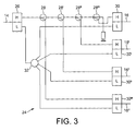
- FIG. 3 A block diagram of network device 24 in accordance with the present invention is shown in Figure 3 .
- the device behaves as a tap unit in the downstream frequency area and as a splitter with equal attenuation for the upstream signals.
- the connected homes have equal attenuation levels on the downstream and also equal levels on the upstream. This gives a serious improvement on the noise-floor of the individual connections.
- diplex filter 26 is connected to input 14 and separates the high frequency downstream signals from the low frequency upstream signals.
- the high frequency signal path is connected to taps 28, 28', 28" and 28"'which are in turn connected to the high pass side of diplex filters 30, 30', 30", and 30'" associated with each output port 16, 16', 16" and 16"'.
- the low pass side of filter 26 is connected to splitter 32 which in turn is connected to the low pass side of each output diplex filter 30, 30', 30", and 30"'. In this way, paths for the high and low frequency signals are separated.
- downstream signals are received at input 14 and pass through the high frequency side of filter 26 to reach taps 28, 28', 28" and 28"'and so pass to output diplex filters 30, 30', 30", and 30"'. From these diplex filters, the signal goes to output ports 16, 16', 16" and 16"' and is received by individual users.
- These downstream signals have different attenuation levels as provided by circuitry associated with the tap ports so as to overcome the different cable lengths associated with each user.
- the upstream signal received from each user is received from outputs 16, 16', 16" and 16'" proceeds through the low frequency side of diplex filters 30, 30', 30" and 30"' to splitter 32 which combines the upstream signals from all users.
- the combined signal is passed to the low frequency side of diplex filter 26 connected to input 14, and sent from input 14 to the network provider 10.
- the present invention can also be used to create level optimisation and so improve the noise level of tap banks. This is particularly useful with the implementation of Docsis 3.0 (a telecommunications standard for data transfer) and channel banding where the level of the upstream signals are reduced. These reductions cause signal level issues from homes to the input of a tapbank. As explained previously, the upstream signal is not so affected by cable loss and as such, not by the cable length. Therefore this will create attenuation differences between the homes and the input of the tap bank. To overcome that problem, different steps (small) on the splitters are preferable. The embodiment of Figure 4 allows one to address both these issues, creating small level steps and reducing the total loss.
- Docsis 3.0 a telecommunications standard for data transfer
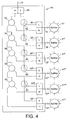
- the downstream and upstream signals are separated within the device by use of a diplex filter 26 connected to input 14 and output diplex filters 30, 30', 30", 30"', 30"", 30 v connected to six outputs 16, 16', 16", 16'", 16"", 16 v .
- the downstream path follows a cascade of splitters. One port of each splitter is connected to the next splitter while the other port goes to a main splitter 41 via the output diplex filter.
- the upstream signal from the main splitters 41, 41', 41", 41'", 41"", 41 v is first split from the downstream signal by each output diplex filter.
- the upstream signal follows a cascade of taps until all upstream signals are combined in a common signal.
- the upstream paths between the low frequency side of diplex filters 26 and 30, 30', 30", 30"', 30"", 30 v are connected to taps 42, 44, 46, 48 and 50 such that each upstream signal in turn passes to a tap where it joins with another upstream signal from another output until at final tap 42 all upstream signals are carried together in a common signal ready to enter diplexer 26 and pass upstream from input 14 to the service provider.
- each upstream signal in turn is fed into a preceding signal until all upstream signals are carried together.
- tap 42 can be set at 2dB, tap 44 at 4dB, tap 46 at 6dB, tap 48 at 8dB and tap 50 at 10dB.
- the tap values are chosen to have the wanted differences between the ports while the total insertion loss is as low as possible.
- the total insertion loss of the upstream signal is much lower than for conventional tap units, with the added noise optimized and the total loss much lower.
- the downstream signal is split using a plurality of cascaded splitters 52, 54, 56, 58, 60 to create 4dB level steps.
- One output from each splitter is connected to the high pass side of an associated output filter and the second output is connected to the input of a successive splitter until the downstream signal is split into substantially equal components for each output.
- the attenuation levels in to out for downstream signals will be 15dB for port 16, 19dB for port 16', 23dB for port 16", 27dB for port 16"', 31dB for port 16"" and 31dB for port 16 v .
- the 4dB steps compensate for the different cable lengths to the home with long cables mounted on ports with high levels and short cable on ports with low levels, as discussed previously. Total insertion loss from the input of the network device to every home can thus be equalized and by way of example will be set to 26dB.
Landscapes
- Engineering & Computer Science (AREA)
- Signal Processing (AREA)
- Multimedia (AREA)
- Computer Networks & Wireless Communication (AREA)
- Two-Way Televisions, Distribution Of Moving Picture Or The Like (AREA)
- Cable Transmission Systems, Equalization Of Radio And Reduction Of Echo (AREA)
- Small-Scale Networks (AREA)
Description
- This invention relates to a cable network device for use in cable television and data transmission networks.
- In cable networks supplying a large number of users, the signal from the network provider is split many times to ensure each user is able to connect into the provider's network, with the last divider or tap unit connecting to a small number of users via individual taps. Signal losses vary between different users, in part due to the length of cable connecting them to the tap unit, and these losses need to be compensated for so that each user has a similar quality signal. To do this, different taps within a unit are associated with different attenuation levels but there are often issues with matching attenuations for signals are being sent to the user (downstream) or sent from the user (upstream) and with ensuring that both downstream and upstream signal quality is the same for each user.
- In accordance with one aspect of the present invention there is provided a cable network device comprising an input connected to a plurality of outputs, connectable to equipment associated with a plurality of end users, wherein the input is connected to each output by first and second electrical communication paths, such that there are a plurality of first and second electrical communication paths, where downstream signals from the input to each output pass along the first electrical communication path and upstream signals from each output to the input pass along the second electrical communication path, and each second electrical communication path has the same attenuation as the other second electrical communication paths.
- For each first electrical communication path or downstream path, typically the attenuation level will vary so that the overall downstream attenuation for each user associated with an output port is kept constant when taking into account the attenuation from within the device and from cables attaching equipment to the outputs. For each second electrical communication path or upstream path, the attenuation along that path within the device will be equal to the attenuation demonstrated by all other second paths and similarly the overall upstream attenuation from the equipment to the input will be equal for each equipment user. Thus with such a device with separated downstream and upstream paths within the device the downstream attenuation for all users is equal and also the upstream attenuation for all users is equal.
- Typically the upstream signals are low frequency, generally in the range 5 to 8MHz, and more preferably 5 to 65MHz, with the downstream signals having a higher frequency, typically in the range 80.6MHz up to 862MHz and beyond.
- According to the invention, the input is connected to a plurality of tap elements, each tap element in communication with one output. The tap elements allow the attenuation of the signal path to be adjusted. Each tap element communicate with an adjoining tap unit and one output such that the tap elements are arranged as a cascade with each output connected to one tap unit.
- The input may be connected to a first filter or first filter means to separate electrical signals into high and low frequency bands, and so separate downstream signals to travel along the first electrical communication path. The filter means may of preference be a diplex filter. Depending on the direction of travel of electrical signals, the filter means will either separate or combine high and low frequency signal components.
- Each output is desirably connected to a second filter or second filter means to separate out low frequency upstream signals passing from the output to the input so that they travel along the second electrical communication path. Again the second filter means may of preference be a diplex filter.
- The input may be connected by way of a splitter means or splitter to each second filter means. The single splitter means combines the upstream signals from each output into one combined signal received by the input for transference to a network provider. By having such a direct connection, with the upstream signal bypassing the tap elements, and so separated from the downstream signal, the upstream low frequency signal follows a separate electrical path to the low frequency signal and reaches the input without being routed through the tap elements.
- Alternatively the input may be connected by way of a plurality of splitter means to each second filter means, each splitter means communicating with an adjoining splitter means and one output. In this arrangement, the plurality of splitter means will split the downstream signal into separate signals for each user.
- The invention will now be described, by way of example, with reference to the accompanying drawings, in which:
-
Figure 1 is a schematic diagram to illustrate downstream signal losses for a number of users within a cable network; -
Figure 2 is a schematic diagram to illustrate upstream signal losses; -
Figure 3 is a schematic diagram of a first embodiment of a cable network device in accordance with the present invention; and -
Figure 4 is a schematic diagram of a second embodiment. - Where a cable television (CATV) or other data and information provider supplies a large number of premises with data, the signal path must be split many times to ensure each user is able to connect into the provider's network.
Figure 1 shows a schematic diagram of a last divider or tap in aCATV network 10 and illustrates the path of downstream signals from thenetwork provider 10 to theuser 20.Tap unit 12 increases the isolation between theinput 14 andoutput ports divider device 12,user homes external network 10 viacoaxial cables coaxial cable 22 varies depending on the length of the cable. The longer the cable, the greater the attenuation. The insertion loss for each output port and the cable attenuation is shown by way of example. - To offer every home the same level of attenuation and so ensure that signal quality is generally the same for each user, the longest cables will be connected to the taps with the lowest insertion loss. Thus
longest cable 22 is connected toport 16 which has the lowest insertion loss of 10dB. The total insertion loss from the input of the tap unit to every home is equalised and in this illustrative example is 26dB. - For upstream signals passing from
user 20 tonetwork provider 10, different losses are seen, seeFigure 2 . The attenuation fromcables tap ports tap unit 12, the attenuation within the tap is added to the attenuation of the signal received from theuser 20. This results in different attenuation levels for the upstream signals. Thus the insertion loss fromhome 20 to the input of the tap for the upstream is 16dB, for home 20' is 18dB,home 20" is 20dB and home 20'" is 22dB. This means a level inequality of 6dB which has a serious impact on the ingress/noise levels on the upstream. - One way to overcome this issue for the upstream signals is to use a splitter with equal attenuation for each port, however this then means the downstream attenuation levels vary which is not correct for the downstream.
- A block diagram of
network device 24 in accordance with the present invention is shown inFigure 3 . The device behaves as a tap unit in the downstream frequency area and as a splitter with equal attenuation for the upstream signals. The connected homes have equal attenuation levels on the downstream and also equal levels on the upstream. This gives a serious improvement on the noise-floor of the individual connections. - Within the
device 24,diplex filter 26 is connected toinput 14 and separates the high frequency downstream signals from the low frequency upstream signals. The high frequency signal path is connected totaps diplex filters output port filter 26 is connected tosplitter 32 which in turn is connected to the low pass side of eachoutput diplex filter - In use within a cable/data network, the downstream signals are received at
input 14 and pass through the high frequency side offilter 26 to reachtaps output diplex filters output ports - The upstream signal received from each user is received from
outputs diplex filters diplex filter 26 connected toinput 14, and sent frominput 14 to thenetwork provider 10. By separating the upstream signals from the downstream signals, and routing the upstream signals separately, one can avoid adding unequal losses to the upstream signal and ensure that the losses upstream are substantially equal for all users. By continuing to route the downstream signal through tap elements, the downstream attenuation can be adjusted to compensate for cable length and other factors and ensure that the downstream attenuation for all users is also substantially identical. Thedevice 24 thus provides for optimal downstream and upstream attenuation. - The present invention can also be used to create level optimisation and so improve the noise level of tap banks. This is particularly useful with the implementation of Docsis 3.0 (a telecommunications standard for data transfer) and channel banding where the level of the upstream signals are reduced. These reductions cause signal level issues from homes to the input of a tapbank. As explained previously, the upstream signal is not so affected by cable loss and as such, not by the cable length. Therefore this will create attenuation differences between the homes and the input of the tap bank. To overcome that problem, different steps (small) on the splitters are preferable. The embodiment of
Figure 4 allows one to address both these issues, creating small level steps and reducing the total loss. - In the
network device 40 ofFigure 4 , again the downstream and upstream signals are separated within the device by use of adiplex filter 26 connected to input 14 and output diplex filters 30, 30', 30", 30"', 30"", 30v connected to sixoutputs main splitter 41 via the output diplex filter. - The upstream signal from the
main splitters diplex filters final tap 42 all upstream signals are carried together in a common signal ready to enterdiplexer 26 and pass upstream frominput 14 to the service provider. Thus each upstream signal in turn is fed into a preceding signal until all upstream signals are carried together. - Each tap has losses from in to out and so the tap levels are adjusted to ensure the attenuation for each upstream signal is the same. Thus by way of example, tap 42 can be set at 2dB, tap 44 at 4dB, tap 46 at 6dB, tap 48 at 8dB and tap 50 at 10dB. The tap values are chosen to have the wanted differences between the ports while the total insertion loss is as low as possible. The total insertion loss of the upstream signal is much lower than for conventional tap units, with the added noise optimized and the total loss much lower.
- For the downstream path from the high pass side of
filter 26 tooutput filters splitters port 16, 19dB for port 16', 23dB forport 16", 27dB forport 16"', 31dB forport 16"" and 31dB forport 16v. The 4dB steps compensate for the different cable lengths to the home with long cables mounted on ports with high levels and short cable on ports with low levels, as discussed previously. Total insertion loss from the input of the network device to every home can thus be equalized and by way of example will be set to 26dB.
Claims (7)
- A cable network device (24) comprising an input (14) connected to a plurality of outputs (16, 16', 16" and 16"'), the input (14) connected to each output (16, 16', 16" and 16"') by first and second electrical communication paths, where downstream signals from the input (14) to each output (16, 16', 16" and 16"') pass along the first electrical communication path and upstream signals from each output to the input (14) pass along the second electrical communication path, characterised in that the input (14) is connected to a plurality of tap elements (28, 28', 28", 28"'), each tap element in communication with an adjoining tap element and one output, and each second electrical communication path having the same attenuation as the other second electrical communication paths.
- A cable network device according to claim 1, wherein the input (14) is connected to a first filter means (26) for separating electrical signals into high and low frequency bands.
- A cable network device according to any of the preceding claims, wherein each output (16; 16'; 16"; and 16"') is connected to a second filter means (30; 30'; 30"; 30"') to separate out upstream signals.
- A cable network device according to claim 3, wherein the input (14) is connected by way of a splitter means (32) to each second filter means (30, 30', 30", 30"').
- A cable network device according to claim 3, wherein the input (14) is connected by way of a plurality of splitter means (52, 54, 56, 58, 60) to each second filter means, each splitter means communicating with an adjoining splitter means (41; 41'; 41"; 41"'; 41""; 41v) and one output (16; 16'; 16"; 16"'; 16""; 16v).
- A cable network device according to any of the preceding claims, wherein the first and second electrical communication paths are separated.
- A cable/data network incorporating one or more cable network devices in accordance with any of claims 1 to 6.
Applications Claiming Priority (2)
| Application Number | Priority Date | Filing Date | Title |
|---|---|---|---|
| GBGB1007457.3A GB201007457D0 (en) | 2010-05-05 | 2010-05-05 | Cable network device |
| PCT/GB2011/050876 WO2011138611A2 (en) | 2010-05-05 | 2011-05-05 | Cable network device |
Publications (2)
| Publication Number | Publication Date |
|---|---|
| EP2567542A2 EP2567542A2 (en) | 2013-03-13 |
| EP2567542B1 true EP2567542B1 (en) | 2016-08-03 |
Family
ID=42290063
Family Applications (1)
| Application Number | Title | Priority Date | Filing Date |
|---|---|---|---|
| EP11723597.8A Revoked EP2567542B1 (en) | 2010-05-05 | 2011-05-05 | Cable network device |
Country Status (4)
| Country | Link |
|---|---|
| EP (1) | EP2567542B1 (en) |
| GB (2) | GB201007457D0 (en) |
| TW (1) | TW201212562A (en) |
| WO (1) | WO2011138611A2 (en) |
Families Citing this family (2)
| Publication number | Priority date | Publication date | Assignee | Title |
|---|---|---|---|---|
| GB201604054D0 (en) * | 2016-03-09 | 2016-04-20 | Technetix Bv | Cable network device |
| GB2613600B (en) * | 2021-12-08 | 2025-03-26 | Technetix Bv | Cable network device |
Citations (6)
| Publication number | Priority date | Publication date | Assignee | Title |
|---|---|---|---|---|
| US5815794A (en) | 1995-09-01 | 1998-09-29 | Cable Television Laboratories, Inc. | Undesirable energy suppression system in the return path of a bidirectional cable network having dynamically allocated time slots |
| US5835844A (en) | 1995-12-29 | 1998-11-10 | General Instrument Corporation | Bidirectional CATV system having losses for equalizing upstream communication gain |
| US20030093811A1 (en) | 2001-11-13 | 2003-05-15 | General Instrument Corporation | Bandwidth directional coupler |
| GB2382473A (en) | 2001-11-21 | 2003-05-28 | Technetix Plc | Cable tap unit |
| EP1505833A2 (en) | 2003-08-06 | 2005-02-09 | Xtend Networks Ltd. | A wideband catv tap device |
| US20070063790A1 (en) | 2005-05-19 | 2007-03-22 | Yeshayahu Strull | Wideband CATV signal splitter device |
Family Cites Families (7)
| Publication number | Priority date | Publication date | Assignee | Title |
|---|---|---|---|---|
| US5845191A (en) * | 1996-07-25 | 1998-12-01 | At&T Corp | Method for asymmetrically attenuating signals in a transmission system |
| US5799239A (en) * | 1996-08-26 | 1998-08-25 | At&T Corp | Asymmetric coupling method for attenuating upstream and downstream signals by different amounts to reduce ingress noise |
| US5745838A (en) * | 1997-03-14 | 1998-04-28 | Tresness Irrevocable Patent Trust | Return path filter |
| US6779197B1 (en) * | 1999-07-02 | 2004-08-17 | Adc Telecommunications, Inc. | Reverse path upstream signaling for status monitoring |
| JP2001275099A (en) * | 2000-03-27 | 2001-10-05 | N Ii C Cable Media Kk | Tap-off and catv system |
| DE60204318T2 (en) * | 2002-10-01 | 2006-01-26 | Huu-Tung Dinh-Debouny | Broadband RF directional coupler with reverse power saving |
| US20070261094A1 (en) * | 2006-05-05 | 2007-11-08 | Tibor Urbanek | Asymmetrical directional coupler |
-
2010
- 2010-05-05 GB GBGB1007457.3A patent/GB201007457D0/en not_active Ceased
-
2011
- 2011-05-05 EP EP11723597.8A patent/EP2567542B1/en not_active Revoked
- 2011-05-05 TW TW100115734A patent/TW201212562A/en unknown
- 2011-05-05 WO PCT/GB2011/050876 patent/WO2011138611A2/en not_active Ceased
- 2011-05-05 GB GB1107455.6A patent/GB2480150B/en active Active
Patent Citations (6)
| Publication number | Priority date | Publication date | Assignee | Title |
|---|---|---|---|---|
| US5815794A (en) | 1995-09-01 | 1998-09-29 | Cable Television Laboratories, Inc. | Undesirable energy suppression system in the return path of a bidirectional cable network having dynamically allocated time slots |
| US5835844A (en) | 1995-12-29 | 1998-11-10 | General Instrument Corporation | Bidirectional CATV system having losses for equalizing upstream communication gain |
| US20030093811A1 (en) | 2001-11-13 | 2003-05-15 | General Instrument Corporation | Bandwidth directional coupler |
| GB2382473A (en) | 2001-11-21 | 2003-05-28 | Technetix Plc | Cable tap unit |
| EP1505833A2 (en) | 2003-08-06 | 2005-02-09 | Xtend Networks Ltd. | A wideband catv tap device |
| US20070063790A1 (en) | 2005-05-19 | 2007-03-22 | Yeshayahu Strull | Wideband CATV signal splitter device |
Non-Patent Citations (2)
| Title |
|---|
| "Cable networks for television signals, sound signals and interactive services - Part 4: Passive wideband equipment for coaxial cable networks", INTERNATIONAL STANDARD 60728-4, August 2007 (2007-08-01), pages 1 - 32, XP082005218 |
| "Diamond™ Line Type I and Type 2 Amplifiers, Reference & Installation Manual", PHILIPS (PHILIPS DOC. 2244001, REV. D), 3 April 2010 (2010-04-03), XP055380289 |
Also Published As
| Publication number | Publication date |
|---|---|
| GB201107455D0 (en) | 2011-06-15 |
| EP2567542A2 (en) | 2013-03-13 |
| WO2011138611A2 (en) | 2011-11-10 |
| WO2011138611A3 (en) | 2012-06-07 |
| TW201212562A (en) | 2012-03-16 |
| GB2480150B (en) | 2016-01-06 |
| GB201007457D0 (en) | 2010-06-16 |
| GB2480150A (en) | 2011-11-09 |
Similar Documents
| Publication | Publication Date | Title |
|---|---|---|
| US20200351470A1 (en) | Method and apparatus for reducing isolation in a home network | |
| US8350641B2 (en) | Band selective isolation bridge for splitter | |
| US8397271B2 (en) | Power divider networks for cable television networks that include multimedia over coax bypass circuits and signal amplifiers that include such power divider networks | |
| US11076129B2 (en) | MoCA entry device | |
| US7138886B2 (en) | Wideband CATV signal splitter device | |
| US20120054819A1 (en) | Home network frequency conditioning device and method | |
| US20120054805A1 (en) | Home network frequency conditioning device | |
| US9923319B2 (en) | Cable television cable tap device | |
| US20050034167A1 (en) | Wideband CATV tap device | |
| US20080018413A1 (en) | Wideband CATV signal splitter device | |
| AU704402B2 (en) | System to reduce gain variance and ingress in CATV return transmissions | |
| KR100887156B1 (en) | HFC Network Distortion and Noise Cancellation System | |
| SE521942C2 (en) | Data communication method and apparatus | |
| JP2004526354A (en) | Multi-band coaxial extender for in-building digital communication systems | |
| US9806844B2 (en) | Electromagnetic signal transport and distribution system | |
| US12126388B2 (en) | Forward and reverse test point circuit with switchable termination for use in an RF amplifier | |
| WO2011138611A2 (en) | Cable network device | |
| US20070261094A1 (en) | Asymmetrical directional coupler | |
| WO2008002056A1 (en) | Trunk bridge amplifier using multi channel diplexer | |
| EP1406384B1 (en) | Reverse gain saving broadband RF couplers | |
| TW202349892A (en) | Full duplex docsis amplifier with legacy upstream support | |
| CN120898414A (en) | Internal reflection cancellation for multiport full-duplex nodes and amplifiers | |
| IL164745A (en) | Wideband catv signal splitter device | |
| JP2001251600A (en) | Video signal-data signal separator and high-frequency transmitter using the separator | |
| MXPA97008810A (en) | System to reduce the variation of gain and income in return transmissions of c |
Legal Events
| Date | Code | Title | Description |
|---|---|---|---|
| PUAI | Public reference made under article 153(3) epc to a published international application that has entered the european phase |
Free format text: ORIGINAL CODE: 0009012 |
|
| 17P | Request for examination filed |
Effective date: 20121031 |
|
| AK | Designated contracting states |
Kind code of ref document: A2 Designated state(s): AL AT BE BG CH CY CZ DE DK EE ES FI FR GB GR HR HU IE IS IT LI LT LU LV MC MK MT NL NO PL PT RO RS SE SI SK SM TR |
|
| DAX | Request for extension of the european patent (deleted) | ||
| 17Q | First examination report despatched |
Effective date: 20130815 |
|
| GRAP | Despatch of communication of intention to grant a patent |
Free format text: ORIGINAL CODE: EPIDOSNIGR1 |
|
| RIC1 | Information provided on ipc code assigned before grant |
Ipc: H04H 60/97 20080101ALI20160331BHEP Ipc: H04N 7/10 20060101AFI20160331BHEP Ipc: H04B 3/48 20060101ALI20160331BHEP Ipc: H04H 20/79 20080101ALI20160331BHEP |
|
| INTG | Intention to grant announced |
Effective date: 20160415 |
|
| RBV | Designated contracting states (corrected) |
Designated state(s): AL AT BE BG CH CY CZ DE DK EE ES FI FR GR HR HU IE IS IT LI LT LU LV MC MK MT NL NO PL PT RO RS SE SI SK SM TR |
|
| GRAS | Grant fee paid |
Free format text: ORIGINAL CODE: EPIDOSNIGR3 |
|
| GRAA | (expected) grant |
Free format text: ORIGINAL CODE: 0009210 |
|
| AK | Designated contracting states |
Kind code of ref document: B1 Designated state(s): AL AT BE BG CH CY CZ DE DK EE ES FI FR GR HR HU IE IS IT LI LT LU LV MC MK MT NL NO PL PT RO RS SE SI SK SM TR |
|
| REG | Reference to a national code |
Ref country code: CH Ref legal event code: EP Ref country code: AT Ref legal event code: REF Ref document number: 817993 Country of ref document: AT Kind code of ref document: T Effective date: 20160815 |
|
| REG | Reference to a national code |
Ref country code: IE Ref legal event code: FG4D |
|
| REG | Reference to a national code |
Ref country code: DE Ref legal event code: R096 Ref document number: 602011028787 Country of ref document: DE |
|
| REG | Reference to a national code |
Ref country code: NL Ref legal event code: MP Effective date: 20160803 |
|
| REG | Reference to a national code |
Ref country code: LT Ref legal event code: MG4D |
|
| REG | Reference to a national code |
Ref country code: AT Ref legal event code: MK05 Ref document number: 817993 Country of ref document: AT Kind code of ref document: T Effective date: 20160803 |
|
| PG25 | Lapsed in a contracting state [announced via postgrant information from national office to epo] |
Ref country code: IT Free format text: LAPSE BECAUSE OF FAILURE TO SUBMIT A TRANSLATION OF THE DESCRIPTION OR TO PAY THE FEE WITHIN THE PRESCRIBED TIME-LIMIT Effective date: 20160803 Ref country code: NL Free format text: LAPSE BECAUSE OF FAILURE TO SUBMIT A TRANSLATION OF THE DESCRIPTION OR TO PAY THE FEE WITHIN THE PRESCRIBED TIME-LIMIT Effective date: 20160803 Ref country code: NO Free format text: LAPSE BECAUSE OF FAILURE TO SUBMIT A TRANSLATION OF THE DESCRIPTION OR TO PAY THE FEE WITHIN THE PRESCRIBED TIME-LIMIT Effective date: 20161103 Ref country code: IS Free format text: LAPSE BECAUSE OF FAILURE TO SUBMIT A TRANSLATION OF THE DESCRIPTION OR TO PAY THE FEE WITHIN THE PRESCRIBED TIME-LIMIT Effective date: 20161203 Ref country code: RS Free format text: LAPSE BECAUSE OF FAILURE TO SUBMIT A TRANSLATION OF THE DESCRIPTION OR TO PAY THE FEE WITHIN THE PRESCRIBED TIME-LIMIT Effective date: 20160803 Ref country code: LT Free format text: LAPSE BECAUSE OF FAILURE TO SUBMIT A TRANSLATION OF THE DESCRIPTION OR TO PAY THE FEE WITHIN THE PRESCRIBED TIME-LIMIT Effective date: 20160803 Ref country code: HR Free format text: LAPSE BECAUSE OF FAILURE TO SUBMIT A TRANSLATION OF THE DESCRIPTION OR TO PAY THE FEE WITHIN THE PRESCRIBED TIME-LIMIT Effective date: 20160803 Ref country code: FI Free format text: LAPSE BECAUSE OF FAILURE TO SUBMIT A TRANSLATION OF THE DESCRIPTION OR TO PAY THE FEE WITHIN THE PRESCRIBED TIME-LIMIT Effective date: 20160803 |
|
| PG25 | Lapsed in a contracting state [announced via postgrant information from national office to epo] |
Ref country code: ES Free format text: LAPSE BECAUSE OF FAILURE TO SUBMIT A TRANSLATION OF THE DESCRIPTION OR TO PAY THE FEE WITHIN THE PRESCRIBED TIME-LIMIT Effective date: 20160803 Ref country code: PL Free format text: LAPSE BECAUSE OF FAILURE TO SUBMIT A TRANSLATION OF THE DESCRIPTION OR TO PAY THE FEE WITHIN THE PRESCRIBED TIME-LIMIT Effective date: 20160803 Ref country code: GR Free format text: LAPSE BECAUSE OF FAILURE TO SUBMIT A TRANSLATION OF THE DESCRIPTION OR TO PAY THE FEE WITHIN THE PRESCRIBED TIME-LIMIT Effective date: 20161104 Ref country code: PT Free format text: LAPSE BECAUSE OF FAILURE TO SUBMIT A TRANSLATION OF THE DESCRIPTION OR TO PAY THE FEE WITHIN THE PRESCRIBED TIME-LIMIT Effective date: 20161205 Ref country code: SE Free format text: LAPSE BECAUSE OF FAILURE TO SUBMIT A TRANSLATION OF THE DESCRIPTION OR TO PAY THE FEE WITHIN THE PRESCRIBED TIME-LIMIT Effective date: 20160803 Ref country code: AT Free format text: LAPSE BECAUSE OF FAILURE TO SUBMIT A TRANSLATION OF THE DESCRIPTION OR TO PAY THE FEE WITHIN THE PRESCRIBED TIME-LIMIT Effective date: 20160803 Ref country code: LV Free format text: LAPSE BECAUSE OF FAILURE TO SUBMIT A TRANSLATION OF THE DESCRIPTION OR TO PAY THE FEE WITHIN THE PRESCRIBED TIME-LIMIT Effective date: 20160803 |
|
| PG25 | Lapsed in a contracting state [announced via postgrant information from national office to epo] |
Ref country code: RO Free format text: LAPSE BECAUSE OF FAILURE TO SUBMIT A TRANSLATION OF THE DESCRIPTION OR TO PAY THE FEE WITHIN THE PRESCRIBED TIME-LIMIT Effective date: 20160803 Ref country code: EE Free format text: LAPSE BECAUSE OF FAILURE TO SUBMIT A TRANSLATION OF THE DESCRIPTION OR TO PAY THE FEE WITHIN THE PRESCRIBED TIME-LIMIT Effective date: 20160803 |
|
| REG | Reference to a national code |
Ref country code: DE Ref legal event code: R026 Ref document number: 602011028787 Country of ref document: DE |
|
| PLBI | Opposition filed |
Free format text: ORIGINAL CODE: 0009260 |
|
| PG25 | Lapsed in a contracting state [announced via postgrant information from national office to epo] |
Ref country code: CZ Free format text: LAPSE BECAUSE OF FAILURE TO SUBMIT A TRANSLATION OF THE DESCRIPTION OR TO PAY THE FEE WITHIN THE PRESCRIBED TIME-LIMIT Effective date: 20160803 Ref country code: DK Free format text: LAPSE BECAUSE OF FAILURE TO SUBMIT A TRANSLATION OF THE DESCRIPTION OR TO PAY THE FEE WITHIN THE PRESCRIBED TIME-LIMIT Effective date: 20160803 Ref country code: BE Free format text: LAPSE BECAUSE OF FAILURE TO SUBMIT A TRANSLATION OF THE DESCRIPTION OR TO PAY THE FEE WITHIN THE PRESCRIBED TIME-LIMIT Effective date: 20160803 Ref country code: SM Free format text: LAPSE BECAUSE OF FAILURE TO SUBMIT A TRANSLATION OF THE DESCRIPTION OR TO PAY THE FEE WITHIN THE PRESCRIBED TIME-LIMIT Effective date: 20160803 Ref country code: SK Free format text: LAPSE BECAUSE OF FAILURE TO SUBMIT A TRANSLATION OF THE DESCRIPTION OR TO PAY THE FEE WITHIN THE PRESCRIBED TIME-LIMIT Effective date: 20160803 Ref country code: BG Free format text: LAPSE BECAUSE OF FAILURE TO SUBMIT A TRANSLATION OF THE DESCRIPTION OR TO PAY THE FEE WITHIN THE PRESCRIBED TIME-LIMIT Effective date: 20161103 |
|
| PLAX | Notice of opposition and request to file observation + time limit sent |
Free format text: ORIGINAL CODE: EPIDOSNOBS2 |
|
| 26 | Opposition filed |
Opponent name: TELESTE OYJ Effective date: 20170502 |
|
| PGFP | Annual fee paid to national office [announced via postgrant information from national office to epo] |
Ref country code: DE Payment date: 20170523 Year of fee payment: 7 |
|
| PG25 | Lapsed in a contracting state [announced via postgrant information from national office to epo] |
Ref country code: LU Free format text: LAPSE BECAUSE OF NON-PAYMENT OF DUE FEES Effective date: 20170531 Ref country code: SI Free format text: LAPSE BECAUSE OF FAILURE TO SUBMIT A TRANSLATION OF THE DESCRIPTION OR TO PAY THE FEE WITHIN THE PRESCRIBED TIME-LIMIT Effective date: 20160803 |
|
| REG | Reference to a national code |
Ref country code: CH Ref legal event code: PL |
|
| PG25 | Lapsed in a contracting state [announced via postgrant information from national office to epo] |
Ref country code: MC Free format text: LAPSE BECAUSE OF FAILURE TO SUBMIT A TRANSLATION OF THE DESCRIPTION OR TO PAY THE FEE WITHIN THE PRESCRIBED TIME-LIMIT Effective date: 20160803 |
|
| REG | Reference to a national code |
Ref country code: IE Ref legal event code: MM4A |
|
| PG25 | Lapsed in a contracting state [announced via postgrant information from national office to epo] |
Ref country code: LI Free format text: LAPSE BECAUSE OF NON-PAYMENT OF DUE FEES Effective date: 20170531 Ref country code: CH Free format text: LAPSE BECAUSE OF NON-PAYMENT OF DUE FEES Effective date: 20170531 |
|
| REG | Reference to a national code |
Ref country code: FR Ref legal event code: ST Effective date: 20180131 |
|
| PG25 | Lapsed in a contracting state [announced via postgrant information from national office to epo] |
Ref country code: LU Free format text: LAPSE BECAUSE OF NON-PAYMENT OF DUE FEES Effective date: 20170505 |
|
| PG25 | Lapsed in a contracting state [announced via postgrant information from national office to epo] |
Ref country code: IE Free format text: LAPSE BECAUSE OF NON-PAYMENT OF DUE FEES Effective date: 20170505 |
|
| PG25 | Lapsed in a contracting state [announced via postgrant information from national office to epo] |
Ref country code: FR Free format text: LAPSE BECAUSE OF NON-PAYMENT OF DUE FEES Effective date: 20170531 |
|
| RDAF | Communication despatched that patent is revoked |
Free format text: ORIGINAL CODE: EPIDOSNREV1 |
|
| STAA | Information on the status of an ep patent application or granted ep patent |
Free format text: STATUS: THE PATENT HAS BEEN GRANTED |
|
| REG | Reference to a national code |
Ref country code: DE Ref legal event code: R064 Ref document number: 602011028787 Country of ref document: DE Ref country code: DE Ref legal event code: R103 Ref document number: 602011028787 Country of ref document: DE |
|
| PG25 | Lapsed in a contracting state [announced via postgrant information from national office to epo] |
Ref country code: MT Free format text: LAPSE BECAUSE OF NON-PAYMENT OF DUE FEES Effective date: 20170505 |
|
| PG25 | Lapsed in a contracting state [announced via postgrant information from national office to epo] |
Ref country code: AL Free format text: LAPSE BECAUSE OF FAILURE TO SUBMIT A TRANSLATION OF THE DESCRIPTION OR TO PAY THE FEE WITHIN THE PRESCRIBED TIME-LIMIT Effective date: 20160803 |
|
| RDAG | Patent revoked |
Free format text: ORIGINAL CODE: 0009271 |
|
| STAA | Information on the status of an ep patent application or granted ep patent |
Free format text: STATUS: PATENT REVOKED |
|
| 27W | Patent revoked |
Effective date: 20180907 |
|
| PG25 | Lapsed in a contracting state [announced via postgrant information from national office to epo] |
Ref country code: MK Free format text: LAPSE BECAUSE OF FAILURE TO SUBMIT A TRANSLATION OF THE DESCRIPTION OR TO PAY THE FEE WITHIN THE PRESCRIBED TIME-LIMIT Effective date: 20160803 |
|
| PG25 | Lapsed in a contracting state [announced via postgrant information from national office to epo] |
Ref country code: CY Free format text: LAPSE BECAUSE OF FAILURE TO SUBMIT A TRANSLATION OF THE DESCRIPTION OR TO PAY THE FEE WITHIN THE PRESCRIBED TIME-LIMIT Effective date: 20160803 |
|
| PG25 | Lapsed in a contracting state [announced via postgrant information from national office to epo] |
Ref country code: TR Free format text: LAPSE BECAUSE OF FAILURE TO SUBMIT A TRANSLATION OF THE DESCRIPTION OR TO PAY THE FEE WITHIN THE PRESCRIBED TIME-LIMIT Effective date: 20160803 |