EP2567131B1 - Electromagnetically operated switching devices and methods of actuation thereof - Google Patents
Electromagnetically operated switching devices and methods of actuation thereof Download PDFInfo
- Publication number
- EP2567131B1 EP2567131B1 EP11720162.4A EP11720162A EP2567131B1 EP 2567131 B1 EP2567131 B1 EP 2567131B1 EP 11720162 A EP11720162 A EP 11720162A EP 2567131 B1 EP2567131 B1 EP 2567131B1
- Authority
- EP
- European Patent Office
- Prior art keywords
- armature
- coil
- moveable portion
- pole piece
- magnetic
- Prior art date
- Legal status (The legal status is an assumption and is not a legal conclusion. Google has not performed a legal analysis and makes no representation as to the accuracy of the status listed.)
- Active
Links
- 238000000034 method Methods 0.000 title description 2
- 230000005291 magnetic effect Effects 0.000 claims description 46
- 230000004907 flux Effects 0.000 claims description 32
- 239000012530 fluid Substances 0.000 claims description 20
- 239000000463 material Substances 0.000 claims description 7
- 230000008878 coupling Effects 0.000 claims description 6
- 238000010168 coupling process Methods 0.000 claims description 6
- 238000005859 coupling reaction Methods 0.000 claims description 6
- 238000004891 communication Methods 0.000 claims description 3
- 238000006073 displacement reaction Methods 0.000 claims 1
- 230000005294 ferromagnetic effect Effects 0.000 description 4
- 238000010276 construction Methods 0.000 description 3
- 230000007797 corrosion Effects 0.000 description 3
- 238000005260 corrosion Methods 0.000 description 3
- 230000035699 permeability Effects 0.000 description 3
- 230000007423 decrease Effects 0.000 description 2
- 230000000694 effects Effects 0.000 description 2
- 239000003302 ferromagnetic material Substances 0.000 description 2
- 229910001220 stainless steel Inorganic materials 0.000 description 2
- 229910000639 Spring steel Inorganic materials 0.000 description 1
- 230000001133 acceleration Effects 0.000 description 1
- XAGFODPZIPBFFR-UHFFFAOYSA-N aluminium Chemical compound [Al] XAGFODPZIPBFFR-UHFFFAOYSA-N 0.000 description 1
- 229910052782 aluminium Inorganic materials 0.000 description 1
- 239000004411 aluminium Substances 0.000 description 1
- 230000004323 axial length Effects 0.000 description 1
- 230000009286 beneficial effect Effects 0.000 description 1
- 230000000295 complement effect Effects 0.000 description 1
- 230000006735 deficit Effects 0.000 description 1
- 239000000696 magnetic material Substances 0.000 description 1
- 239000012858 resilient material Substances 0.000 description 1
- 238000009738 saturating Methods 0.000 description 1
- 239000007787 solid Substances 0.000 description 1
- 238000004804 winding Methods 0.000 description 1
Images


Classifications
-
- F—MECHANICAL ENGINEERING; LIGHTING; HEATING; WEAPONS; BLASTING
- F16—ENGINEERING ELEMENTS AND UNITS; GENERAL MEASURES FOR PRODUCING AND MAINTAINING EFFECTIVE FUNCTIONING OF MACHINES OR INSTALLATIONS; THERMAL INSULATION IN GENERAL
- F16K—VALVES; TAPS; COCKS; ACTUATING-FLOATS; DEVICES FOR VENTING OR AERATING
- F16K31/00—Actuating devices; Operating means; Releasing devices
- F16K31/02—Actuating devices; Operating means; Releasing devices electric; magnetic
- F16K31/06—Actuating devices; Operating means; Releasing devices electric; magnetic using a magnet, e.g. diaphragm valves, cutting off by means of a liquid
- F16K31/0682—Actuating devices; Operating means; Releasing devices electric; magnetic using a magnet, e.g. diaphragm valves, cutting off by means of a liquid with an articulated or pivot armature
-
- F—MECHANICAL ENGINEERING; LIGHTING; HEATING; WEAPONS; BLASTING
- F16—ENGINEERING ELEMENTS AND UNITS; GENERAL MEASURES FOR PRODUCING AND MAINTAINING EFFECTIVE FUNCTIONING OF MACHINES OR INSTALLATIONS; THERMAL INSULATION IN GENERAL
- F16K—VALVES; TAPS; COCKS; ACTUATING-FLOATS; DEVICES FOR VENTING OR AERATING
- F16K31/00—Actuating devices; Operating means; Releasing devices
- F16K31/02—Actuating devices; Operating means; Releasing devices electric; magnetic
- F16K31/06—Actuating devices; Operating means; Releasing devices electric; magnetic using a magnet, e.g. diaphragm valves, cutting off by means of a liquid
- F16K31/08—Actuating devices; Operating means; Releasing devices electric; magnetic using a magnet, e.g. diaphragm valves, cutting off by means of a liquid using a permanent magnet
- F16K31/082—Actuating devices; Operating means; Releasing devices electric; magnetic using a magnet, e.g. diaphragm valves, cutting off by means of a liquid using a permanent magnet using a electromagnet and a permanent magnet
Definitions
- the present invention relates to electromagnetically operated switching devices and methods for the operation of such devices. More particularly, it is concerned with improving the magnetic structure of these devices. It is also directed at the provision of sealed fast flow switching devices.
- EP-A-1303719 (filed by the present applicant) describes an electromagnetically operated device of the form shown in present Figure 1 .
- a linear armature 10 is sandwiched between two internal pole pieces 12, 14 which are themselves sandwiched between two permanent magnets 16, 18.
- Two external members 20, 22 extend beyond the end of the sandwich of magnets and at their remote ends provide two inwardly facing poles 24, 26.
- the two internal pole pieces 12, 14 extend beyond the permanent magnets 16, 18 where they are surrounded by a coil former 30 on which a coil 32 is wound.
- Two cylindrical inserts 34, 36 are fitted in the poles 24, 26 and the opposed inner ends of the inserts define orifices 38, 40.
- the armature can be deflected and a magnetic field induced by a current flowing in the coil 32. Depending on the direction of current flow in the coil, the armature will be attracted to the pole 26 and insert 36, as shown in solid outline in Figure 1 , or towards the other pole 24 and insert 34, as shown in dashed outline.
- the present invention provides an electromagnetically operated device according to claim 1.
- the container therefore restricts flux leakage in radial directions relative to the coil axis, containing flux generated within the device and shielding the interior from external magnetic flux.
- the permanent magnets are aligned with the moveable portion of the armature. They are disposed along the direction of movement of the moveable portion of the armature. This configuration provides a more compact arrangement relative to the known device described above, as the permanent magnets are incorporated in the pole pieces on opposite sides of the moveable portion of the armature, instead of occupying additional space on the opposite side of the coil.
- This magnet location also improves the linkage of flux from the magnets with the armature.
- the lines of flux from one permanent magnet to the other are formed in substantially straight paths therebetween, with the moveable portion of the armature located in these paths.
- Each permanent magnet may be located adjacent to a respective stable rest position of the armature.
- the permanent magnets are able to exert a stronger magnetic holding force on the armature as they are provided on the same side of the coil as the armature (with respect to the axis of the coil).
- the permanent magnets are provided remotely from and laterally spaced from the direction of movement of the armature.
- Their flux is linked to the armature along an extended magnetic path via the external members 20, 22 and the inwardly extending poles 24, 26.
- a greater proportion of the magnetic flux generated by the permanent magnets is linked across the gap in which the moveable portion of the armature is located, so that their flux is more efficiently concentrated in the region containing the moveable portion of the armature.
- the device may include a magnetic flux container which extends circumferentially around the permanent magnets and the coil with respect to the axis of the coil, wherein a magnetic circuit comprising the armature, the container and a pole piece is formed when the moveable portion of the armature is in each of its stable rest positions.
- the magnetic flux container also substantially extends over one or both ends of the device, relative to the axis of the coil.
- This arrangement provides a substantially magnetically sealed device with minimal flux leakage.
- the shielding effects of the container also serve to avoid the performance of the device being affected by external magnetic fields.
- components of the device provide a magnetic flux container which substantially encloses the interior of the device to avoid flux leakage.
- the container preferably forms the housing of the device which supports the components within it, providing a compact configuration. This results in a strong, well-protected mechanical construction without requiring an additional housing around the device.
- the armature may comprise flexible material to facilitate movement of a moveable portion relative to the remainder of the armature.
- the armature may be rigid and the whole of the armature moves or pivots in operation of the device.
- the armature is resiliently biased towards a location between its stable rest positions. This serves to assist acceleration of the armature from one rest position towards the other, thereby reducing the electrical energy required to shift the armature from one position to the other.
- the armature may comprise resilient material.
- the location to which the moveable portion is resiliently biased may be closer to one pole piece than the other, providing an unsymmetrical bistable operation. This affords a stronger holding force in one stable position relative to the other, which may be beneficial in some applications.
- the device may define first and second fluid ports, with a respective port being closed when the moveable portion of the armature is in each of its stable rest positions.
- the device may be configured to operate as a fluid flow control device.
- each of the first and second ports is in fluid communication with a fluid path defined by a respective pole piece. Definition of fluid paths to the ports in this way achieves a more compact configuration for the device.
- the device may define a third fluid port, with a fluid path between the third port and one of the first and second ports being defined by the device when the other of the first and second ports is closed.
- At least part of the moveable portion of the armature may extend within the coil. This allows the length of the moveable portion to be greater than would otherwise be the case. This means that the range of travel of its distal end can be greater. A greater flow rate from each of the first and second ports may therefore be permitted as a result of the armature lying a greater distance away from the open port when in the stable rest position which closes the other port.
- the moveable portion of the armature is pivotably coupled to a support within the device by a flexible coupling.
- the moveable portion of the armature is arranged to extend laterally over the support adjacent to the coupling. This provides an additional surface area for linkage of magnetic flux between the armature and the support. This wider magnetic path may be desirable in some configurations to avoid magnetic saturation.
- the armature extends into the support and the armature itself forms the flexible coupling between the moveable portion and a fixed portion held by the support. This provides a simpler construction relative to provision of a hinge for example.
- the support is provided by a magnetic core of the coil of the device.
- FIG. 2 An electromagnetically operated device embodying the invention is depicted in Figures 2 , 3A , 3B and 4 .
- the device is housed in a container formed by container body 50 and an end cap 52.
- the container body is in the form of a hollow cylinder open at one end and having an end portion 53 at the other, with the open end engaged by end cap 52.
- the container body is formed of a material having a high magnetic permeability. It may comprise ferromagnetic material.
- the end cap may also be formed of a high magnetic permeability material, so that a magnetic flux container is formed by the container body and end cap in combination which surrounds the interior of the device. Alternatively, in some applications the end cap may be formed from non-magnetic material, such as aluminium.
- a coil 54 is mounted on the end portion 53 of the container body, coaxially with respect to the body.
- a coil core is provided centrally within the windings of the coil.
- the core is divided into two halves 56 and 58.
- the coil core may extend through the end portion 53 of the container body or be contained within it.
- the core extends axially inwards, partway through the coil.
- a pair of pole pieces 60 and 62 are provided between the coil and the end cap. They extend radially inwards from the cylindrical wall of the container body to define opposing, spaced apart pole piece faces 64, 66.
- Each pole piece 60, 62 includes a ferromagnetic extension 65, 67, a permanent magnet 68, 70 and a ferromagnetic end piece 69, 71.
- Each ferromagnetic extension extends between the container body 50 and a respective magnet to space each magnet from the body and so reduce flux leakage to the exterior.
- the end pieces are carried by respective magnets and form the pole piece faces.
- Each permanent magnet 68, 70 has its North and South poles aligned radially with respect to the central longitudinal axis 73 of the container, and they are orientated such that pole piece 60 forms a South pole at pole piece face 64 and pole piece 62 forms a North pole at pole piece face 66.
- the end pieces 69, 71 are provided to protect the permanent magnets 68, 70 from mechanical wear during use of the device. They are preferably formed of a corrosion resistant material such as ferritic chromium steel (for example SS430 or XP13).
- a non-magnetic end cap 52 is shown in Figure 2 , as the cap is relatively close to the magnets 68, 70 to reduce the axial length of the device. If the cap is spaced further away from the magnets 68, 70, so that the distance from the cap to the magnets is substantially greater than the length of the air gap between the pole end pieces 69, 71, the cap may comprise a material having a high magnetic permeability to form part of the magnetic flux container with the container body 50. Spacing the magnetic cap from the magnets in this manner sufficiently reduces internal flux leakage from one magnet to the other via the end cap, which otherwise lessens the amount of useable flux acting on a moving part of the armature.
- Each pole piece defines a respective fluid path 72a, 72b therethrough, extending from the exterior of the device, through the container body wall, to first and second ports 74, 76 defined in the pole piece faces 64, 66.
- a resiliently compressible ring seal 78, 80 is provided in each pole piece face 64, 66 around each port 74, 76.
- the ferromagnetic extensions 65, 67 may extend radially outwards through the container body 50 to form tubular portions defining fluid paths 72a, 72b beyond the container.
- a laminar armature 82 extends along the axis of the device.
- a first portion 82a is fixed in position and sandwiched between the coil core pieces 56, 58.
- a second armature portion 82b extends into the device away from the coil cores, through and beyond the coil 54 and between the pole piece faces 64, 66.
- the armature is formed of a resilient, magnetisable material so that portion 82b is able to flex between one end of its travel in which it is in contact with pole piece face 64 (and/or seal 78), and the other end of its travel in which it is contact with pole piece face 66 (and/or seal 80).
- the permanent magnets are located along the direction of movement of the armature. Preferably they are also in close proximity to the armature. These features improve the linkage of magnetic flux between the magnets and the armature.
- the armature may comprise spring steel.
- it may comprise ferritic chromium steel (for example SS430 or XP13).
- the pole piece faces lie in parallel planes
- armature portion 82b is tapered such that its thickness decreases with increasing distance from the coil core so that in each end of travel position, it engages the respective pole piece face with a surface that is substantially parallel to the plane of the pole piece face, thereby closing off the respective port (see Figures 3A and 3B ).
- the armature portion 82b may have parallel sides, with the pole pieces faces being angled or shaped so as to complement the profile of the armature portion in each end of its travel contact positions.
- End cap 52 defines a third fluid port 84, in fluid communication with an end cap channel 86 which extends from port 84 to the exterior of the device.
- the container body 50 extends continuously and circumferentially around the coil 54 and also circumferentially surrounds the magnets 68, 70.
- End portion 53 of the container body extends radially inwardly from one end of the cylindrical wall of the container body, over the outer end face of the coil 54, and meets or extends over the outer end of the coil core (56, 58).
- the device In operation, the device is bistable. Its two stable rest positions are shown in Figures 3A and 3B .
- armature portion 82b In Figure 3A armature portion 82b is attracted to pole piece 60 by permanent magnet 68.
- Application of a pulse of current to the coil 54 polarises the second portion 82b of the armature.
- the armature portion 82b if the direction of the current through the coil forms a South pole in the armature portion 82b, it is repelled by the South pole of permanent magnet 68, and attracted by the North pole of magnet 70.
- the armature portion 82b is switched from its stable rest position in engagement with pole piece face 64 to its other stable rest position, in contact with pole piece face 66, as shown in Figure 3B .
- armature portion 82b encourages a rapid take-off action of the armature towards the other pole piece as soon as the magnetic attraction force is less than the mechanical spring force generated by the armature. This means that less electrical energy needs to be inputted into the coil in order to switch the device. A pulse length of less than 1 millisecond may be sufficient.
- a closed magnetic circuit is formed by the armature, the coil core, the container body and one of the pole pieces. This serves to minimise flux leakage from the device.
- the coil core extends only partway through the coil to accommodate a longer second armature portion 82b (in contrast to the known configuration shown in Figure 1 ). This improves the trade-off between the range of travel of the armature between its stable rest positions and the amount of stress experienced by the armature as it flexes. With a longer travel, a higher flow rate is permitted via the ports 74, 76.
- the container body wall 50 is cylindrical where it extends between the pole pieces. This maintains a significant spacing between the container body wall and the permanent magnets 68, 70 and serves to reduce flux linkage from one magnet to the other via the container of the device.
- the device may be operated to control fluid flows in a number of ways by application of appropriate current pulses to the coil 54.
- a high pressure supply connected to end cap port 84 may be coupled to end cap port 84 by closing second port 76 with the armature.
- a load coupled to end cap port 84 may subsequently discharge fluid to second port 76 after the armature has been switched to close first port 74.
- a high pressure supply coupled to end cap port may be connected to the first port 74, or vice-versa, whilst the armature closes off second port 76.
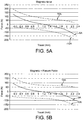
- Figure 5A shows only the magnetic forces acting on the armature. It can be seen that either side of the mid-point of its travel at 1.2 mm, the armature is biased towards one of the pole pieces as a result of the net force exerted by the permanent magnets 68, 70, giving its bistable characteristic. If a 10A pulse is applied to the coil in either direction (as shown by the dashed lines), it can be seen that the resultant force acting on the armature is sufficient to overcome the forces exerted by the permanent magnets at any position in its travel, and force the armature to one of its two stable rest positions.
- the container configuration serves to effectively magnetically seal the device without the need for a separate housing for this purpose.
- the container also serves to pneumatically/hydraulically seal the interior.
- the compact self-contained configuration allows use of the device as a "plug-in" valve, providing a space efficient multi-valve capability.
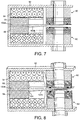
- Figure 6 depicts another electromagnetically operated switching device in accordance with the present invention. Its structure and operation are similar to that of the embodiment described above in relation to Figures 2 to 5B . It differs in that it is not surrounded by a magnetic container which also pneumatically or hydraulically seals off the interior of the device.
- the device of Figure 6 has an open-sided construction.
- a magnetic return path via each permanent magnet back to the coil core 56, 58 is provided by a U-shaped support formed of ferromagnetic material.
- the support is formed by two L-shaped supports 90, 92, one being the mirror image of the other.
- the U-shaped support may instead be fabricated in a single piece for example.
- the pole pieces 60, 62 are mounted at one end of a limb of each of the supports 90, 92.
- the other limb of each support extends over the outer end face of the coil 54 and a respective coil core 56, 58.
- the cross-section of each support is large enough to provide a good magnetic return path, to substantially contain flux generated during operation of the device without saturating.
- the device may be inserted into a separate fluidically sealed container. It provides a bistable valve able to withstand a positive or negative pressure difference between the interior of the device and the surrounding environment.
- FIG. 7 and 8 The embodiment depicted in Figures 7 and 8 is similar to that of Figure 6 , except that an alternative armature configuration is included.
- moveable portion 82b of the armature has a constant cross-section as it extends away from the coil cores 56, 58 and its end portion is tapered such that the thickness of the laminar armature decreases towards its distal end.
- magnetic saturation may occur during operation of the device due to the cross-section of the magnetic flux path provided by the armature where it meets the coil core being insufficient.
- This issue is addressed in the embodiment of Figures 7 and 8 .
- the moveable portion 102b of the armature in this embodiment has been modified so that it extends laterally over the end faces of the coil cores 56, 58 in close proximity to those faces.
- the thickness of the moveable portion of the armature is increased close to the coil cores, by increasing the dimension normal to the plane of the armature.
- the cross-sectional area of the laterally extended end of the moveable portion is significantly greater than that of the fixed portion of the armature.
- Gap 104 is configured to be wide enough to provide sufficient flexibility in the armature, whilst being narrow enough to provide for sufficient flux linkage across it from the armature into the coil cores.
Landscapes
- Engineering & Computer Science (AREA)
- General Engineering & Computer Science (AREA)
- Mechanical Engineering (AREA)
- Physics & Mathematics (AREA)
- Electromagnetism (AREA)
- Magnetically Actuated Valves (AREA)
- Electromagnets (AREA)
- Electrically Driven Valve-Operating Means (AREA)
- Multiple-Way Valves (AREA)
Description
- The present invention relates to electromagnetically operated switching devices and methods for the operation of such devices. More particularly, it is concerned with improving the magnetic structure of these devices. It is also directed at the provision of sealed fast flow switching devices.
-
EP-A-1303719 (filed by the present applicant) describes an electromagnetically operated device of the form shown in presentFigure 1 . - A
linear armature 10 is sandwiched between twointernal pole pieces permanent magnets external members poles - The two
internal pole pieces permanent magnets coil 32 is wound. Twocylindrical inserts poles orifices - The armature can be deflected and a magnetic field induced by a current flowing in the
coil 32. Depending on the direction of current flow in the coil, the armature will be attracted to thepole 26 andinsert 36, as shown in solid outline inFigure 1 , or towards theother pole 24 andinsert 34, as shown in dashed outline. - In the known configuration shown in
Figure 1 , there areregions - This is likely to be problematic in applications where the device is surrounded by fluid, as there will be a risk of build up of magnetic debris in these regions potentially leading to flow impairment or even blockages. Furthermore, the flux leakage may interfere with the operation of other adjacent devices. Similarly, the device may be susceptible to the influence of external magnetic.
- Other electromagnetical devices are known from
DE 3528090 C1 ,DE 2345638 B1 ,US 4225835 A ,US 4602230 A andWO0204851 A1 - The present invention provides an electromagnetically operated device according to
claim 1. The container therefore restricts flux leakage in radial directions relative to the coil axis, containing flux generated within the device and shielding the interior from external magnetic flux.
The permanent magnets are aligned with the moveable portion of the armature. They are disposed along the direction of movement of the moveable portion of the armature. This configuration provides a more compact arrangement relative to the known device described above, as the permanent magnets are incorporated in the pole pieces on opposite sides of the moveable portion of the armature, instead of occupying additional space on the opposite side of the coil. - This magnet location also improves the linkage of flux from the magnets with the armature. The lines of flux from one permanent magnet to the other are formed in substantially straight paths therebetween, with the moveable portion of the armature located in these paths.
- Each permanent magnet may be located adjacent to a respective stable rest position of the armature. In this configuration, the permanent magnets are able to exert a stronger magnetic holding force on the armature as they are provided on the same side of the coil as the armature (with respect to the axis of the coil). This is in contrast to the known arrangement discussed above, in which the permanent magnets are provided remotely from and laterally spaced from the direction of movement of the armature. Their flux is linked to the armature along an extended magnetic path via the
external members poles - The device may include a magnetic flux container which extends circumferentially around the permanent magnets and the coil with respect to the axis of the coil, wherein a magnetic circuit comprising the armature, the container and a pole piece is formed when the moveable portion of the armature is in each of its stable rest positions.
- Preferably, the magnetic flux container also substantially extends over one or both ends of the device, relative to the axis of the coil. This arrangement provides a substantially magnetically sealed device with minimal flux leakage. The shielding effects of the container also serve to avoid the performance of the device being affected by external magnetic fields. In a preferred configuration, components of the device provide a magnetic flux container which substantially encloses the interior of the device to avoid flux leakage.
- The container preferably forms the housing of the device which supports the components within it, providing a compact configuration. This results in a strong, well-protected mechanical construction without requiring an additional housing around the device.
- The armature may comprise flexible material to facilitate movement of a moveable portion relative to the remainder of the armature. Alternatively, the armature may be rigid and the whole of the armature moves or pivots in operation of the device. Preferably, the armature is resiliently biased towards a location between its stable rest positions. This serves to assist acceleration of the armature from one rest position towards the other, thereby reducing the electrical energy required to shift the armature from one position to the other. To achieve this, the armature may comprise resilient material.
- In some embodiments, the location to which the moveable portion is resiliently biased may be closer to one pole piece than the other, providing an unsymmetrical bistable operation. This affords a stronger holding force in one stable position relative to the other, which may be beneficial in some applications.
- The device may define first and second fluid ports, with a respective port being closed when the moveable portion of the armature is in each of its stable rest positions. Thus, the device may be configured to operate as a fluid flow control device.
- Preferably, each of the first and second ports is in fluid communication with a fluid path defined by a respective pole piece. Definition of fluid paths to the ports in this way achieves a more compact configuration for the device.
- The device may define a third fluid port, with a fluid path between the third port and one of the first and second ports being defined by the device when the other of the first and second ports is closed.
- At least part of the moveable portion of the armature may extend within the coil. This allows the length of the moveable portion to be greater than would otherwise be the case. This means that the range of travel of its distal end can be greater. A greater flow rate from each of the first and second ports may therefore be permitted as a result of the armature lying a greater distance away from the open port when in the stable rest position which closes the other port.
- The moveable portion of the armature is pivotably coupled to a support within the device by a flexible coupling. The moveable portion of the armature is arranged to extend laterally over the support adjacent to the coupling. This provides an additional surface area for linkage of magnetic flux between the armature and the support. This wider magnetic path may be desirable in some configurations to avoid magnetic saturation.
- The armature extends into the support and the armature itself forms the flexible coupling between the moveable portion and a fixed portion held by the support. This provides a simpler construction relative to provision of a hinge for example.
- The support is provided by a magnetic core of the coil of the device.
- Embodiments of the invention will now be described by way of example and with reference to the accompanying schematic drawings wherein:
-
Figure 1 is a cross-sectional side view of a known electromagnetically operated device; -
Figure 2 is a cross-sectional perspective side view of an electromagnetically operated device in accordance with the present invention; -
Figures 3A and 3B are cross-sectional side views of the actuator ofFigure 2 , with its armature in each of its stable rest positions; -
Figure 4 is a cross-sectional perspective view of the device shown inFigure 2 with its end cap removed; -
Figures 5A and 5B are graphs of magnetic force, and magnetic and flexure forces combined, respectively, as exerted on the device armature plotted against the position of the armature in its range of travel; -
Figure 6 is a perspective view of another embodiment of a device according to the invention; and -
Figures 7 and 8 are cross-sectional side and perspective views, respectively, of a further embodiment of the invention. - It should be noted that the Figures are diagrammatic and not drawn to scale. Relative dimensions and proportions of these Figures have been shown exaggerated or reduced in size, for the sake of clarity and convenience in the drawings. The same reference signs are generally used to refer to corresponding or similar features in modified and different embodiments.
- An electromagnetically operated device embodying the invention is depicted in
Figures 2 ,3A ,3B and4 . The device is housed in a container formed bycontainer body 50 and anend cap 52. The container body is in the form of a hollow cylinder open at one end and having anend portion 53 at the other, with the open end engaged byend cap 52. - The container body is formed of a material having a high magnetic permeability. It may comprise ferromagnetic material. The end cap may also be formed of a high magnetic permeability material, so that a magnetic flux container is formed by the container body and end cap in combination which surrounds the interior of the device. Alternatively, in some applications the end cap may be formed from non-magnetic material, such as aluminium.
- A
coil 54 is mounted on theend portion 53 of the container body, coaxially with respect to the body. A coil core is provided centrally within the windings of the coil. The core is divided into twohalves end portion 53 of the container body or be contained within it. The core extends axially inwards, partway through the coil. - A pair of
pole pieces pole piece ferromagnetic extension permanent magnet ferromagnetic end piece container body 50 and a respective magnet to space each magnet from the body and so reduce flux leakage to the exterior. The end pieces are carried by respective magnets and form the pole piece faces. Eachpermanent magnet longitudinal axis 73 of the container, and they are orientated such thatpole piece 60 forms a South pole atpole piece face 64 andpole piece 62 forms a North pole atpole piece face 66. - The
end pieces permanent magnets - A
non-magnetic end cap 52 is shown inFigure 2 , as the cap is relatively close to themagnets magnets pole end pieces container body 50. Spacing the magnetic cap from the magnets in this manner sufficiently reduces internal flux leakage from one magnet to the other via the end cap, which otherwise lessens the amount of useable flux acting on a moving part of the armature. - Each pole piece defines a respective
fluid path second ports compressible ring seal pole piece face port - The
ferromagnetic extensions container body 50 to form tubular portions definingfluid paths - A
laminar armature 82 extends along the axis of the device. Afirst portion 82a is fixed in position and sandwiched between thecoil core pieces second armature portion 82b extends into the device away from the coil cores, through and beyond thecoil 54 and between the pole piece faces 64, 66. The armature is formed of a resilient, magnetisable material so thatportion 82b is able to flex between one end of its travel in which it is in contact with pole piece face 64 (and/or seal 78), and the other end of its travel in which it is contact with pole piece face 66 (and/or seal 80). The permanent magnets are located along the direction of movement of the armature. Preferably they are also in close proximity to the armature. These features improve the linkage of magnetic flux between the magnets and the armature. - The armature may comprise spring steel. For greater corrosion resistance, it may comprise ferritic chromium steel (for example SS430 or XP13).
- Where appropriate, internal surfaces other than the engagement surfaces of the
end pieces armature 82 are coated or sealed off in some way from fluids present in the interior of the device to prevent corrosion. - In the embodiment illustrated, the pole piece faces lie in parallel planes, and
armature portion 82b is tapered such that its thickness decreases with increasing distance from the coil core so that in each end of travel position, it engages the respective pole piece face with a surface that is substantially parallel to the plane of the pole piece face, thereby closing off the respective port (seeFigures 3A and 3B ). Alternatively, thearmature portion 82b may have parallel sides, with the pole pieces faces being angled or shaped so as to complement the profile of the armature portion in each end of its travel contact positions. -
End cap 52 defines a thirdfluid port 84, in fluid communication with anend cap channel 86 which extends fromport 84 to the exterior of the device. - The
container body 50 extends continuously and circumferentially around thecoil 54 and also circumferentially surrounds themagnets End portion 53 of the container body extends radially inwardly from one end of the cylindrical wall of the container body, over the outer end face of thecoil 54, and meets or extends over the outer end of the coil core (56, 58). - In operation, the device is bistable. Its two stable rest positions are shown in
Figures 3A and 3B . InFigure 3A armature portion 82b is attracted topole piece 60 bypermanent magnet 68. Application of a pulse of current to thecoil 54 polarises thesecond portion 82b of the armature. In the case ofFigure 3A , if the direction of the current through the coil forms a South pole in thearmature portion 82b, it is repelled by the South pole ofpermanent magnet 68, and attracted by the North pole ofmagnet 70. Thus, thearmature portion 82b is switched from its stable rest position in engagement with pole piece face 64 to its other stable rest position, in contact withpole piece face 66, as shown inFigure 3B . - The resilient nature of
armature portion 82b encourages a rapid take-off action of the armature towards the other pole piece as soon as the magnetic attraction force is less than the mechanical spring force generated by the armature. This means that less electrical energy needs to be inputted into the coil in order to switch the device. A pulse length of less than 1 millisecond may be sufficient. - In each stable rest position, a closed magnetic circuit is formed by the armature, the coil core, the container body and one of the pole pieces. This serves to minimise flux leakage from the device.
- The coil core extends only partway through the coil to accommodate a longer
second armature portion 82b (in contrast to the known configuration shown inFigure 1 ). This improves the trade-off between the range of travel of the armature between its stable rest positions and the amount of stress experienced by the armature as it flexes. With a longer travel, a higher flow rate is permitted via theports - It can be seen in
Figure 4 that thecontainer body wall 50 is cylindrical where it extends between the pole pieces. This maintains a significant spacing between the container body wall and thepermanent magnets - It will appreciated that the device may be operated to control fluid flows in a number of ways by application of appropriate current pulses to the
coil 54. - For example, it may be employed to selectively switch a high pressure supply connected to end
cap port 84 to thefirst port 74 orsecond port 76. In another application, a high pressure supply connected to port 74 may be coupled to endcap port 84 by closingsecond port 76 with the armature. A load coupled to endcap port 84 may subsequently discharge fluid tosecond port 76 after the armature has been switched to closefirst port 74. In a further mode of operation, a high pressure supply coupled to end cap port may be connected to thefirst port 74, or vice-versa, whilst the armature closes offsecond port 76. - Forces acting on the armature over its range of travel are plotted in
Figures 5A and 5B . -
Figure 5A shows only the magnetic forces acting on the armature. It can be seen that either side of the mid-point of its travel at 1.2 mm, the armature is biased towards one of the pole pieces as a result of the net force exerted by thepermanent magnets - In
Figure 5B , the effect of the flexure force resulting from the resilience of the armature is taken into account. It can be seen that this increases the magnitude of the resultant force experienced by the armature when a current pulse is applied to switch the armature from one stable rest position to the other. - The container configuration according to corresponding embodiments of the invention serves to effectively magnetically seal the device without the need for a separate housing for this purpose. The container also serves to pneumatically/hydraulically seal the interior.
- The compact self-contained configuration allows use of the device as a "plug-in" valve, providing a space efficient multi-valve capability.
-
Figure 6 depicts another electromagnetically operated switching device in accordance with the present invention. Its structure and operation are similar to that of the embodiment described above in relation toFigures 2 to 5B . It differs in that it is not surrounded by a magnetic container which also pneumatically or hydraulically seals off the interior of the device. - The device of
Figure 6 has an open-sided construction. A magnetic return path via each permanent magnet back to thecoil core Figure 6 , the support is formed by two L-shapedsupports - The
pole pieces supports coil 54 and arespective coil core - The device may be inserted into a separate fluidically sealed container. It provides a bistable valve able to withstand a positive or negative pressure difference between the interior of the device and the surrounding environment.
- The embodiment depicted in
Figures 7 and 8 is similar to that ofFigure 6 , except that an alternative armature configuration is included. InFigure 6 , it can be seen thatmoveable portion 82b of the armature has a constant cross-section as it extends away from thecoil cores - In some applications, magnetic saturation may occur during operation of the device due to the cross-section of the magnetic flux path provided by the armature where it meets the coil core being insufficient. This issue is addressed in the embodiment of
Figures 7 and 8 . It can be seen that themoveable portion 102b of the armature in this embodiment has been modified so that it extends laterally over the end faces of thecoil cores narrow gap 104 between the end faces of thecoil cores armature portion 102b. This provides a wider magnetic flux path without compromising the flexibility of the armature, which is facilitated by the narrow neck portion that extends acrossgap 104. As shown in the Figures, themoveable portion 102b extends an equal distance either side of the neck portion. The thickness of the armature then tapers with increasing distance away from the coil cores to present opposed faces for engagement in parallel with the plane of a respective pole piece end face. -
Gap 104 is configured to be wide enough to provide sufficient flexibility in the armature, whilst being narrow enough to provide for sufficient flux linkage across it from the armature into the coil cores.
Claims (11)
- An electromagnetically operated device comprising:an armature (82) comprising a magnetisable and moveable portion (82b) for displacement between two stable rest positions;two pole pieces (60, 62) being disposed on opposite sides of the armature, the pole pieces forming poles of opposing polarity adjacent to the armature, and the armature being magnetically attracted to a respective pole piece in each of its stable rest positions; anda coil (54) being arranged to polarise the moveable portion of the armature when the coil is energised, such that the moveable portion of the armature is displaced from one stable rest position to the other by energising the coil so as to polarise the portion to the opposite polarity to the adjacent pole piece,each pole piece (60, 62) comprising a permanent magnet (68, 70) with the permanent magnets being disposed on opposite sides of the moveable portion of the armature,characterized in that, the coil has a magnetic core (56, 58) andthe moveable portion of the armature is pivotally coupled by a flexible coupling to the magnetic core (56, 58) of the coil, with the armature extending into the magnetic core, and with the magnetic core extending only part way through the coil.
- A device according to claim 1, wherein the armature comprises flexible material to facilitate movement of its moveable portion.
- A device according to claim 1 or claim 2, wherein the moveable portion is resiliently biased towards a location between its stable rest positions.
- A device according to claim 3, wherein the location is closer to one pole piece than the other.
- A device according to any preceding claim including a magnetic flux container (50) extending circumferentially around the permanent magnets and the coil with respect to the axis of the coil, wherein a magnetic circuit comprising the armature, the container and a pole piece is formed when the moveable portion of the armature is in each of its stable rest positions.
- A device according to any preceding claim, wherein the device defines first and second fluid ports (72a,72b), and a respective port is closed when the moveable portion of the armature is in each of its stable rest positions.
- A device according to claim 6, wherein each of the first and second ports is in fluid communication with a fluid path defined by a respective pole piece.
- A device according to claim 6 or claim 7, wherein the device defines a third fluid port (84), and a fluid path between the third port and one of the first and second ports is defined by the device when the other of the first and second ports is closed.
- A device according to any preceding claim, wherein at least part of the moveable portion of the armature extends within the coil.
- A device according to any preceding claim, wherein:
the moveable portion of the armature extends laterally over the coil core adjacent to the coupling to provide an additional surface area for linkage of magnetic flux between the armature and the magnetic core. - A device according to any preceding claim, wherein the armature itself forms the flexible coupling.
Applications Claiming Priority (3)
| Application Number | Priority Date | Filing Date | Title |
|---|---|---|---|
| GBGB1007458.1A GB201007458D0 (en) | 2010-05-05 | 2010-05-05 | Electromagnetically operated switching devices and methods of actuation thereof |
| GB1102452A GB2480346A (en) | 2010-05-05 | 2011-02-11 | Electromagnetically operated valve |
| PCT/GB2011/050863 WO2011138599A1 (en) | 2010-05-05 | 2011-05-03 | Electromagnetically operated swiching devices and methods of actuation thereof |
Publications (2)
| Publication Number | Publication Date |
|---|---|
| EP2567131A1 EP2567131A1 (en) | 2013-03-13 |
| EP2567131B1 true EP2567131B1 (en) | 2019-01-02 |
Family
ID=42290064
Family Applications (1)
| Application Number | Title | Priority Date | Filing Date |
|---|---|---|---|
| EP11720162.4A Active EP2567131B1 (en) | 2010-05-05 | 2011-05-03 | Electromagnetically operated switching devices and methods of actuation thereof |
Country Status (9)
| Country | Link |
|---|---|
| US (1) | US9046187B2 (en) |
| EP (1) | EP2567131B1 (en) |
| JP (1) | JP5932772B2 (en) |
| KR (1) | KR20130114579A (en) |
| CN (1) | CN102918310B (en) |
| BR (1) | BR112012028103A2 (en) |
| DK (1) | DK2567131T3 (en) |
| GB (2) | GB201007458D0 (en) |
| WO (1) | WO2011138599A1 (en) |
Cited By (6)
| Publication number | Priority date | Publication date | Assignee | Title |
|---|---|---|---|---|
| WO2021115827A1 (en) | 2019-12-10 | 2021-06-17 | Haldex Brake Products Aktiebolag | Brake system of a commercial vehicle |
| WO2021115826A1 (en) | 2019-09-26 | 2021-06-17 | Haldex Brake Products Aktiebolag | Commercial vehicle brake system |
| WO2021121940A1 (en) | 2019-12-20 | 2021-06-24 | Haldex Brake Products Aktiebolag | Commercial vehicle brake valve actuator and commercial vehicle brake valve |
| DE202021103036U1 (en) | 2021-06-04 | 2021-07-20 | Haldex Brake Products Aktiebolag | Vehicle wheel control unit and steering and / or braking system of a vehicle |
| DE202020104139U1 (en) | 2020-07-17 | 2021-10-20 | Haldex Brake Products Aktiebolag | Swivel armature brake valve actuator |
| DE112019007382T5 (en) | 2019-06-03 | 2022-02-17 | Haldex Brake Products Aktiebolag | Pneumatic vehicle brake assembly |
Families Citing this family (12)
| Publication number | Priority date | Publication date | Assignee | Title |
|---|---|---|---|---|
| US20120199768A1 (en) * | 2011-02-03 | 2012-08-09 | Love Lonnie J | Mesofluidic digital valve |
| US10060546B2 (en) * | 2014-04-09 | 2018-08-28 | Kongsberg Automotive Ab | Solenoid valve |
| DE102016203024A1 (en) * | 2016-02-26 | 2017-08-31 | Zf Friedrichshafen Ag | Electromagnetic valve with spring tongues |
| WO2019101817A1 (en) * | 2017-11-21 | 2019-05-31 | Haldex Brake Products Ab | A valve and a valve assembly |
| GB2568546B (en) | 2017-11-21 | 2022-10-05 | Haldex Brake Prod Ab | A valve and valve component |
| DE102017131246A1 (en) * | 2017-12-22 | 2019-06-27 | Bürkert Werke GmbH & Co. KG | Valve with electrodynamic actuator |
| US10855158B2 (en) * | 2018-04-19 | 2020-12-01 | Watasensor, Inc. | Magnetic power generation |
| EP3597937B1 (en) * | 2018-07-20 | 2022-12-28 | Hamilton Sundstrand Corporation | Servo valve |
| US11353135B1 (en) * | 2019-03-02 | 2022-06-07 | Facebook Technologies, Llc | Magnetic fluidic valves and related systems and methods |
| GB2583697B (en) * | 2019-04-08 | 2023-12-27 | Haldex Brake Prod Ab | Control and monitoring method for a valve |
| WO2019170925A2 (en) | 2019-06-03 | 2019-09-12 | Haldex Brake Products Aktiebolag | Electropneumatic brake system for a utility vehicle and utility vehicle comprising an electropneumatic brake system |
| EP3808619B1 (en) | 2019-10-18 | 2023-08-09 | Haldex Brake Products Aktiebolag | Autonomously driven vehicle |
Family Cites Families (19)
| Publication number | Priority date | Publication date | Assignee | Title |
|---|---|---|---|---|
| US2832866A (en) * | 1952-12-17 | 1958-04-29 | Gen Railway Signal Co | Polarized relay |
| US3215162A (en) * | 1962-04-20 | 1965-11-02 | Ford Motor Co | Bistable control valve |
| US3379214A (en) * | 1965-01-15 | 1968-04-23 | Skinner Prec Ind Inc | Permanent magnet valve assembly |
| US3457955A (en) * | 1967-01-03 | 1969-07-29 | Garrett Corp | Aerodynamically balanced valve |
| US3570807A (en) * | 1969-01-14 | 1971-03-16 | Bell Aerospace Corp | Electromechanical control valve |
| US3532121A (en) * | 1969-01-15 | 1970-10-06 | Bell Aerospace Corp | Latching valve |
| DE2345638B1 (en) | 1973-04-13 | 1974-06-20 | Hans Sauer | Electromagnetic relay |
| DE2749468A1 (en) | 1976-11-15 | 1978-05-18 | Iskra | ELECTROMAGNETIC RELAY |
| GB1591471A (en) * | 1977-06-18 | 1981-06-24 | Hart J C H | Electromagnetic actuators |
| DE3347602A1 (en) * | 1983-12-30 | 1985-07-11 | Siemens AG, 1000 Berlin und 8000 München | POLARIZED ELECTROMAGNETIC RELAY |
| DE3528090C1 (en) | 1985-08-05 | 1986-10-23 | SDS-Relais AG, 8024 Deisenhofen | Electromagnetic relay |
| US6598621B1 (en) * | 1998-04-01 | 2003-07-29 | Camcon Ltd. | Magnetic drives |
| GB2342504B (en) * | 1998-10-08 | 2003-04-23 | Wladyslaw Wygnanski | Magnetic drives |
| GB2380064B (en) * | 1998-10-08 | 2003-05-14 | Camcon Ltd | Magnetic drives |
| US7021603B2 (en) * | 1998-10-08 | 2006-04-04 | Wladyslaw Wygnaski | Electromagnetic actuator and integrated actuator and fluid flow control valve |
| GB0016505D0 (en) | 2000-07-06 | 2000-08-23 | Wygnanski Wladyslaw | Improved electro-magnetic device |
| US6512435B2 (en) * | 2001-04-25 | 2003-01-28 | Charles Willard | Bistable electro-magnetic mechanical actuator |
| JP2005183262A (en) * | 2003-12-22 | 2005-07-07 | Matsushita Electric Works Ltd | Single stable type polar electromagnetic relay |
| JP4435727B2 (en) * | 2005-10-14 | 2010-03-24 | ナブテスコ株式会社 | Brake control device |
-
2010
- 2010-05-05 GB GBGB1007458.1A patent/GB201007458D0/en not_active Ceased
-
2011
- 2011-02-11 GB GB1102452A patent/GB2480346A/en not_active Withdrawn
- 2011-05-03 CN CN201180022393.0A patent/CN102918310B/en not_active Expired - Fee Related
- 2011-05-03 DK DK11720162.4T patent/DK2567131T3/en active
- 2011-05-03 JP JP2013508550A patent/JP5932772B2/en active Active
- 2011-05-03 BR BR112012028103A patent/BR112012028103A2/en not_active Application Discontinuation
- 2011-05-03 EP EP11720162.4A patent/EP2567131B1/en active Active
- 2011-05-03 WO PCT/GB2011/050863 patent/WO2011138599A1/en active Application Filing
- 2011-05-03 US US13/643,813 patent/US9046187B2/en active Active
- 2011-05-03 KR KR1020127031916A patent/KR20130114579A/en not_active Application Discontinuation
Non-Patent Citations (1)
| Title |
|---|
| None * |
Cited By (6)
| Publication number | Priority date | Publication date | Assignee | Title |
|---|---|---|---|---|
| DE112019007382T5 (en) | 2019-06-03 | 2022-02-17 | Haldex Brake Products Aktiebolag | Pneumatic vehicle brake assembly |
| WO2021115826A1 (en) | 2019-09-26 | 2021-06-17 | Haldex Brake Products Aktiebolag | Commercial vehicle brake system |
| WO2021115827A1 (en) | 2019-12-10 | 2021-06-17 | Haldex Brake Products Aktiebolag | Brake system of a commercial vehicle |
| WO2021121940A1 (en) | 2019-12-20 | 2021-06-24 | Haldex Brake Products Aktiebolag | Commercial vehicle brake valve actuator and commercial vehicle brake valve |
| DE202020104139U1 (en) | 2020-07-17 | 2021-10-20 | Haldex Brake Products Aktiebolag | Swivel armature brake valve actuator |
| DE202021103036U1 (en) | 2021-06-04 | 2021-07-20 | Haldex Brake Products Aktiebolag | Vehicle wheel control unit and steering and / or braking system of a vehicle |
Also Published As
| Publication number | Publication date |
|---|---|
| DK2567131T3 (en) | 2019-04-23 |
| GB201007458D0 (en) | 2010-06-16 |
| KR20130114579A (en) | 2013-10-17 |
| JP2013525713A (en) | 2013-06-20 |
| GB2480346A (en) | 2011-11-16 |
| GB201102452D0 (en) | 2011-03-30 |
| US9046187B2 (en) | 2015-06-02 |
| WO2011138599A1 (en) | 2011-11-10 |
| BR112012028103A2 (en) | 2017-10-10 |
| JP5932772B2 (en) | 2016-06-08 |
| CN102918310B (en) | 2014-10-29 |
| CN102918310A (en) | 2013-02-06 |
| US20130087726A1 (en) | 2013-04-11 |
| EP2567131A1 (en) | 2013-03-13 |
Similar Documents
| Publication | Publication Date | Title |
|---|---|---|
| EP2567131B1 (en) | Electromagnetically operated switching devices and methods of actuation thereof | |
| EP2359376B1 (en) | Multistable electromagnetic actuators | |
| US8567440B2 (en) | Solenoid operated valve | |
| EP2499646B1 (en) | Solenoid actuator | |
| EP2064472B1 (en) | Bistable valve | |
| US10190699B2 (en) | Electromagnetic actuator and valve | |
| US10054244B2 (en) | Shut-off gas valve | |
| US6028499A (en) | Monophase, short travel, electromagnetic actuator having a good electric power/force ratio | |
| US20130328650A1 (en) | Divergent flux path magnetic actuator and devices incorporating the same | |
| EP1381803B1 (en) | Electromagnetically operated valve | |
| US5226627A (en) | Magnetic valve | |
| JP6097185B2 (en) | Shut-off valve | |
| KR100927139B1 (en) | Solenoid actuator with permanent magnet and solenoid valve using same | |
| GB2379726A (en) | Electro-magnetically operated device | |
| EP3297004B1 (en) | Electromagnetic actuator with rocking armature | |
| JPH10238648A (en) | Solenoid valve | |
| JP3251085B2 (en) | solenoid valve | |
| GB2394028A (en) | Valves | |
| CZ37379U1 (en) | An electromagnetic coaxial valve | |
| CZ37380U1 (en) | An electromagnetic coaxial valve with pressure regulation | |
| GB2387968A (en) | Electromagnetically operated valve | |
| JPH0198782A (en) | Valve gear |
Legal Events
| Date | Code | Title | Description |
|---|---|---|---|
| PUAI | Public reference made under article 153(3) epc to a published international application that has entered the european phase |
Free format text: ORIGINAL CODE: 0009012 |
|
| 17P | Request for examination filed |
Effective date: 20121011 |
|
| AK | Designated contracting states |
Kind code of ref document: A1 Designated state(s): AL AT BE BG CH CY CZ DE DK EE ES FI FR GB GR HR HU IE IS IT LI LT LU LV MC MK MT NL NO PL PT RO RS SE SI SK SM TR |
|
| DAX | Request for extension of the european patent (deleted) | ||
| GRAP | Despatch of communication of intention to grant a patent |
Free format text: ORIGINAL CODE: EPIDOSNIGR1 |
|
| STAA | Information on the status of an ep patent application or granted ep patent |
Free format text: STATUS: GRANT OF PATENT IS INTENDED |
|
| INTG | Intention to grant announced |
Effective date: 20180712 |
|
| GRAS | Grant fee paid |
Free format text: ORIGINAL CODE: EPIDOSNIGR3 |
|
| GRAA | (expected) grant |
Free format text: ORIGINAL CODE: 0009210 |
|
| STAA | Information on the status of an ep patent application or granted ep patent |
Free format text: STATUS: THE PATENT HAS BEEN GRANTED |
|
| AK | Designated contracting states |
Kind code of ref document: B1 Designated state(s): AL AT BE BG CH CY CZ DE DK EE ES FI FR GB GR HR HU IE IS IT LI LT LU LV MC MK MT NL NO PL PT RO RS SE SI SK SM TR |
|
| REG | Reference to a national code |
Ref country code: GB Ref legal event code: FG4D |
|
| REG | Reference to a national code |
Ref country code: CH Ref legal event code: EP Ref country code: AT Ref legal event code: REF Ref document number: 1084810 Country of ref document: AT Kind code of ref document: T Effective date: 20190115 |
|
| REG | Reference to a national code |
Ref country code: DE Ref legal event code: R096 Ref document number: 602011055334 Country of ref document: DE |
|
| REG | Reference to a national code |
Ref country code: IE Ref legal event code: FG4D |
|
| REG | Reference to a national code |
Ref country code: DK Ref legal event code: T3 Effective date: 20190415 |
|
| REG | Reference to a national code |
Ref country code: NL Ref legal event code: FP |
|
| REG | Reference to a national code |
Ref country code: LT Ref legal event code: MG4D |
|
| RAP2 | Party data changed (patent owner data changed or rights of a patent transferred) |
Owner name: SILVERWELL TECHNOLOGY LIMITED |
|
| REG | Reference to a national code |
Ref country code: AT Ref legal event code: MK05 Ref document number: 1084810 Country of ref document: AT Kind code of ref document: T Effective date: 20190102 |
|
| REG | Reference to a national code |
Ref country code: NO Ref legal event code: T2 Effective date: 20190102 |
|
| REG | Reference to a national code |
Ref country code: NL Ref legal event code: HC Owner name: SILVERWELL TECHNOLOGY LIMITED; GB Free format text: DETAILS ASSIGNMENT: CHANGE OF OWNER(S), CHANGE OF OWNER(S) NAME; FORMER OWNER NAME: CAMCON OIL LIMITED Effective date: 20190603 |
|
| PG25 | Lapsed in a contracting state [announced via postgrant information from national office to epo] |
Ref country code: LT Free format text: LAPSE BECAUSE OF FAILURE TO SUBMIT A TRANSLATION OF THE DESCRIPTION OR TO PAY THE FEE WITHIN THE PRESCRIBED TIME-LIMIT Effective date: 20190102 Ref country code: PL Free format text: LAPSE BECAUSE OF FAILURE TO SUBMIT A TRANSLATION OF THE DESCRIPTION OR TO PAY THE FEE WITHIN THE PRESCRIBED TIME-LIMIT Effective date: 20190102 Ref country code: ES Free format text: LAPSE BECAUSE OF FAILURE TO SUBMIT A TRANSLATION OF THE DESCRIPTION OR TO PAY THE FEE WITHIN THE PRESCRIBED TIME-LIMIT Effective date: 20190102 Ref country code: FI Free format text: LAPSE BECAUSE OF FAILURE TO SUBMIT A TRANSLATION OF THE DESCRIPTION OR TO PAY THE FEE WITHIN THE PRESCRIBED TIME-LIMIT Effective date: 20190102 Ref country code: PT Free format text: LAPSE BECAUSE OF FAILURE TO SUBMIT A TRANSLATION OF THE DESCRIPTION OR TO PAY THE FEE WITHIN THE PRESCRIBED TIME-LIMIT Effective date: 20190502 Ref country code: SE Free format text: LAPSE BECAUSE OF FAILURE TO SUBMIT A TRANSLATION OF THE DESCRIPTION OR TO PAY THE FEE WITHIN THE PRESCRIBED TIME-LIMIT Effective date: 20190102 |
|
| PG25 | Lapsed in a contracting state [announced via postgrant information from national office to epo] |
Ref country code: LV Free format text: LAPSE BECAUSE OF FAILURE TO SUBMIT A TRANSLATION OF THE DESCRIPTION OR TO PAY THE FEE WITHIN THE PRESCRIBED TIME-LIMIT Effective date: 20190102 Ref country code: BG Free format text: LAPSE BECAUSE OF FAILURE TO SUBMIT A TRANSLATION OF THE DESCRIPTION OR TO PAY THE FEE WITHIN THE PRESCRIBED TIME-LIMIT Effective date: 20190402 Ref country code: IS Free format text: LAPSE BECAUSE OF FAILURE TO SUBMIT A TRANSLATION OF THE DESCRIPTION OR TO PAY THE FEE WITHIN THE PRESCRIBED TIME-LIMIT Effective date: 20190502 Ref country code: RS Free format text: LAPSE BECAUSE OF FAILURE TO SUBMIT A TRANSLATION OF THE DESCRIPTION OR TO PAY THE FEE WITHIN THE PRESCRIBED TIME-LIMIT Effective date: 20190102 Ref country code: GR Free format text: LAPSE BECAUSE OF FAILURE TO SUBMIT A TRANSLATION OF THE DESCRIPTION OR TO PAY THE FEE WITHIN THE PRESCRIBED TIME-LIMIT Effective date: 20190403 Ref country code: HR Free format text: LAPSE BECAUSE OF FAILURE TO SUBMIT A TRANSLATION OF THE DESCRIPTION OR TO PAY THE FEE WITHIN THE PRESCRIBED TIME-LIMIT Effective date: 20190102 |
|
| REG | Reference to a national code |
Ref country code: DE Ref legal event code: R097 Ref document number: 602011055334 Country of ref document: DE |
|
| PG25 | Lapsed in a contracting state [announced via postgrant information from national office to epo] |
Ref country code: AL Free format text: LAPSE BECAUSE OF FAILURE TO SUBMIT A TRANSLATION OF THE DESCRIPTION OR TO PAY THE FEE WITHIN THE PRESCRIBED TIME-LIMIT Effective date: 20190102 Ref country code: CZ Free format text: LAPSE BECAUSE OF FAILURE TO SUBMIT A TRANSLATION OF THE DESCRIPTION OR TO PAY THE FEE WITHIN THE PRESCRIBED TIME-LIMIT Effective date: 20190102 Ref country code: SK Free format text: LAPSE BECAUSE OF FAILURE TO SUBMIT A TRANSLATION OF THE DESCRIPTION OR TO PAY THE FEE WITHIN THE PRESCRIBED TIME-LIMIT Effective date: 20190102 Ref country code: RO Free format text: LAPSE BECAUSE OF FAILURE TO SUBMIT A TRANSLATION OF THE DESCRIPTION OR TO PAY THE FEE WITHIN THE PRESCRIBED TIME-LIMIT Effective date: 20190102 Ref country code: AT Free format text: LAPSE BECAUSE OF FAILURE TO SUBMIT A TRANSLATION OF THE DESCRIPTION OR TO PAY THE FEE WITHIN THE PRESCRIBED TIME-LIMIT Effective date: 20190102 Ref country code: EE Free format text: LAPSE BECAUSE OF FAILURE TO SUBMIT A TRANSLATION OF THE DESCRIPTION OR TO PAY THE FEE WITHIN THE PRESCRIBED TIME-LIMIT Effective date: 20190102 Ref country code: IT Free format text: LAPSE BECAUSE OF FAILURE TO SUBMIT A TRANSLATION OF THE DESCRIPTION OR TO PAY THE FEE WITHIN THE PRESCRIBED TIME-LIMIT Effective date: 20190102 |
|
| PLBE | No opposition filed within time limit |
Free format text: ORIGINAL CODE: 0009261 |
|
| STAA | Information on the status of an ep patent application or granted ep patent |
Free format text: STATUS: NO OPPOSITION FILED WITHIN TIME LIMIT |
|
| PG25 | Lapsed in a contracting state [announced via postgrant information from national office to epo] |
Ref country code: SM Free format text: LAPSE BECAUSE OF FAILURE TO SUBMIT A TRANSLATION OF THE DESCRIPTION OR TO PAY THE FEE WITHIN THE PRESCRIBED TIME-LIMIT Effective date: 20190102 |
|
| REG | Reference to a national code |
Ref country code: DE Ref legal event code: R119 Ref document number: 602011055334 Country of ref document: DE |
|
| 26N | No opposition filed |
Effective date: 20191003 |
|
| REG | Reference to a national code |
Ref country code: CH Ref legal event code: PL |
|
| PG25 | Lapsed in a contracting state [announced via postgrant information from national office to epo] |
Ref country code: CH Free format text: LAPSE BECAUSE OF NON-PAYMENT OF DUE FEES Effective date: 20190531 Ref country code: MC Free format text: LAPSE BECAUSE OF FAILURE TO SUBMIT A TRANSLATION OF THE DESCRIPTION OR TO PAY THE FEE WITHIN THE PRESCRIBED TIME-LIMIT Effective date: 20190102 Ref country code: LI Free format text: LAPSE BECAUSE OF NON-PAYMENT OF DUE FEES Effective date: 20190531 |
|
| REG | Reference to a national code |
Ref country code: BE Ref legal event code: MM Effective date: 20190531 |
|
| PG25 | Lapsed in a contracting state [announced via postgrant information from national office to epo] |
Ref country code: SI Free format text: LAPSE BECAUSE OF FAILURE TO SUBMIT A TRANSLATION OF THE DESCRIPTION OR TO PAY THE FEE WITHIN THE PRESCRIBED TIME-LIMIT Effective date: 20190102 Ref country code: LU Free format text: LAPSE BECAUSE OF NON-PAYMENT OF DUE FEES Effective date: 20190503 |
|
| PG25 | Lapsed in a contracting state [announced via postgrant information from national office to epo] |
Ref country code: TR Free format text: LAPSE BECAUSE OF FAILURE TO SUBMIT A TRANSLATION OF THE DESCRIPTION OR TO PAY THE FEE WITHIN THE PRESCRIBED TIME-LIMIT Effective date: 20190102 |
|
| PG25 | Lapsed in a contracting state [announced via postgrant information from national office to epo] |
Ref country code: DE Free format text: LAPSE BECAUSE OF NON-PAYMENT OF DUE FEES Effective date: 20191203 Ref country code: IE Free format text: LAPSE BECAUSE OF NON-PAYMENT OF DUE FEES Effective date: 20190503 |
|
| PG25 | Lapsed in a contracting state [announced via postgrant information from national office to epo] |
Ref country code: BE Free format text: LAPSE BECAUSE OF NON-PAYMENT OF DUE FEES Effective date: 20190531 |
|
| PG25 | Lapsed in a contracting state [announced via postgrant information from national office to epo] |
Ref country code: CY Free format text: LAPSE BECAUSE OF FAILURE TO SUBMIT A TRANSLATION OF THE DESCRIPTION OR TO PAY THE FEE WITHIN THE PRESCRIBED TIME-LIMIT Effective date: 20190102 |
|
| PG25 | Lapsed in a contracting state [announced via postgrant information from national office to epo] |
Ref country code: MT Free format text: LAPSE BECAUSE OF FAILURE TO SUBMIT A TRANSLATION OF THE DESCRIPTION OR TO PAY THE FEE WITHIN THE PRESCRIBED TIME-LIMIT Effective date: 20190102 Ref country code: HU Free format text: LAPSE BECAUSE OF FAILURE TO SUBMIT A TRANSLATION OF THE DESCRIPTION OR TO PAY THE FEE WITHIN THE PRESCRIBED TIME-LIMIT; INVALID AB INITIO Effective date: 20110503 |
|
| PG25 | Lapsed in a contracting state [announced via postgrant information from national office to epo] |
Ref country code: MK Free format text: LAPSE BECAUSE OF FAILURE TO SUBMIT A TRANSLATION OF THE DESCRIPTION OR TO PAY THE FEE WITHIN THE PRESCRIBED TIME-LIMIT Effective date: 20190102 |
|
| PGFP | Annual fee paid to national office [announced via postgrant information from national office to epo] |
Ref country code: FR Payment date: 20230309 Year of fee payment: 13 |
|
| PGFP | Annual fee paid to national office [announced via postgrant information from national office to epo] |
Ref country code: GB Payment date: 20230309 Year of fee payment: 13 |
|
| PGFP | Annual fee paid to national office [announced via postgrant information from national office to epo] |
Ref country code: NL Payment date: 20230314 Year of fee payment: 13 |
|
| P01 | Opt-out of the competence of the unified patent court (upc) registered |
Effective date: 20230525 |
|
| PGFP | Annual fee paid to national office [announced via postgrant information from national office to epo] |
Ref country code: NO Payment date: 20230510 Year of fee payment: 13 Ref country code: DK Payment date: 20230511 Year of fee payment: 13 |
|
| PGFP | Annual fee paid to national office [announced via postgrant information from national office to epo] |
Ref country code: NL Payment date: 20240315 Year of fee payment: 14 |