EP2566276A1 - Mobile communication method and mobile station - Google Patents
Mobile communication method and mobile station Download PDFInfo
- Publication number
- EP2566276A1 EP2566276A1 EP11775095A EP11775095A EP2566276A1 EP 2566276 A1 EP2566276 A1 EP 2566276A1 EP 11775095 A EP11775095 A EP 11775095A EP 11775095 A EP11775095 A EP 11775095A EP 2566276 A1 EP2566276 A1 EP 2566276A1
- Authority
- EP
- European Patent Office
- Prior art keywords
- mobile station
- carrier
- downlink
- radio base
- uplink
- Prior art date
- Legal status (The legal status is an assumption and is not a legal conclusion. Google has not performed a legal analysis and makes no representation as to the accuracy of the status listed.)
- Ceased
Links
Images



Classifications
-
- H—ELECTRICITY
- H04—ELECTRIC COMMUNICATION TECHNIQUE
- H04W—WIRELESS COMMUNICATION NETWORKS
- H04W72/00—Local resource management
- H04W72/04—Wireless resource allocation
-
- H—ELECTRICITY
- H04—ELECTRIC COMMUNICATION TECHNIQUE
- H04L—TRANSMISSION OF DIGITAL INFORMATION, e.g. TELEGRAPHIC COMMUNICATION
- H04L5/00—Arrangements affording multiple use of the transmission path
- H04L5/0001—Arrangements for dividing the transmission path
- H04L5/0003—Two-dimensional division
- H04L5/0005—Time-frequency
- H04L5/0007—Time-frequency the frequencies being orthogonal, e.g. OFDM(A) or DMT
- H04L5/001—Time-frequency the frequencies being orthogonal, e.g. OFDM(A) or DMT the frequencies being arranged in component carriers
-
- H—ELECTRICITY
- H04—ELECTRIC COMMUNICATION TECHNIQUE
- H04W—WIRELESS COMMUNICATION NETWORKS
- H04W52/00—Power management, e.g. Transmission Power Control [TPC] or power classes
- H04W52/04—Transmission power control [TPC]
- H04W52/06—TPC algorithms
- H04W52/14—Separate analysis of uplink or downlink
- H04W52/146—Uplink power control
-
- H—ELECTRICITY
- H04—ELECTRIC COMMUNICATION TECHNIQUE
- H04W—WIRELESS COMMUNICATION NETWORKS
- H04W52/00—Power management, e.g. Transmission Power Control [TPC] or power classes
- H04W52/04—Transmission power control [TPC]
- H04W52/18—TPC being performed according to specific parameters
- H04W52/24—TPC being performed according to specific parameters using SIR [Signal to Interference Ratio] or other wireless path parameters
- H04W52/242—TPC being performed according to specific parameters using SIR [Signal to Interference Ratio] or other wireless path parameters taking into account path loss
-
- H—ELECTRICITY
- H04—ELECTRIC COMMUNICATION TECHNIQUE
- H04W—WIRELESS COMMUNICATION NETWORKS
- H04W72/00—Local resource management
- H04W72/20—Control channels or signalling for resource management
- H04W72/23—Control channels or signalling for resource management in the downlink direction of a wireless link, i.e. towards a terminal
-
- H—ELECTRICITY
- H04—ELECTRIC COMMUNICATION TECHNIQUE
- H04W—WIRELESS COMMUNICATION NETWORKS
- H04W52/00—Power management, e.g. Transmission Power Control [TPC] or power classes
- H04W52/04—Transmission power control [TPC]
- H04W52/06—TPC algorithms
- H04W52/16—Deriving transmission power values from another channel
-
- H—ELECTRICITY
- H04—ELECTRIC COMMUNICATION TECHNIQUE
- H04W—WIRELESS COMMUNICATION NETWORKS
- H04W52/00—Power management, e.g. Transmission Power Control [TPC] or power classes
- H04W52/04—Transmission power control [TPC]
- H04W52/38—TPC being performed in particular situations
- H04W52/42—TPC being performed in particular situations in systems with time, space, frequency or polarisation diversity
Definitions
- the present invention relates to a mobile communication method and a mobile station.
- a mobile station UE is configured to be able to perform a CA (Carrier Aggregation) communication with a radio base station eNB by using a plurality of DL CCs (Downlink Component Carriers) and a plurality of UL CCs (Uplink Component Carriers), which have carrier frequencies different from each other.
- CA Carrier Aggregation
- each CC used in the CA communication can be set in an active state or a deactive state.
- the mobile station UE is configured to control transmission power in PUSCH (Physical Uplink Shared Channel, an uplink shared channel), transmission power in PUCCH (Physical Uplink Control Channel, an uplink control channel), transmission power of SRS (Sounding Reference Signal), transmission power in PRACH (Physical Random Access Channel), and the like on the basis of path loss (Pathloss) estimated from predetermined DL CC.
- PUSCH Physical Uplink Shared Channel, an uplink shared channel
- PUCCH Physical Uplink Control Channel
- SRS Sounding Reference Signal
- PRACH Physical Random Access Channel
- the mobile station UE is configured to calculate the path loss in the predetermined DL CC by using the difference between transmission power (Resource Element unit) of a downlink common pilot signal (a cell-specific reference signal) in the radio base station eNB and received power (Resource Element unit) of the downlink common pilot signal in the mobile station UE.
- the transmission power of the downlink common pilot signal in the radio base station eNB is broadcasted by the radio base station eNB.
- the mobile station UE is notified from the radio base station eNB of from which DL CC the path loss used for controlling the transmission power in each UL CC should be calculated.
- the mobile station UE does not frequently monitor DL CC in a deactive state, and thus it is not possible to ensure the estimation accuracy of path loss in the DL CC.
- the present invention has been achieved in view of the above-described problems, and an object thereof is to provide a mobile communication method and a mobile station, by which it is possible to reduce interference in a CA communication.
- a first characteristic of the present embodiment is summarized in that a mobile communication method, in which a mobile station communicates with a radio base station by using a plurality of downlink carriers and a plurality of uplink carriers, each of which has a different carrier frequency, includes: a step A of receiving, by the mobile station, a scheduling signal for permitting the mobile station to transmit an uplink data signal in a predetermined uplink carrier through a physical downlink control channel in a first downlink carrier; and a step B of discarding, by the mobile station, the scheduling signal when transmission power of the predetermined uplink carrier is controlled on the basis of path loss estimated from a second downlink carrier in a deactive state.
- a second characteristic of the present embodiment is summarized in that a mobile station configured to be capable of communicating with a radio base station by using a plurality of downlink carriers and a plurality of uplink carriers, each of which has a different carrier frequency, includes: a reception unit configured to receive a scheduling signal for permitting the mobile station to transmit an uplink data signal in a predetermined uplink carrier through a physical downlink control channel in a first downlink carrier, wherein, when transmission power of the predetermined uplink carrier is controlled on the basis of path loss estimated from a second downlink carrier in a deactive state, the reception unit is configured to discard the scheduling signal.
- the present invention it is possible to provide a mobile communication method and a mobile station, by which it is possible to reduce interference in a CA communication.
- the mobile communication system according to the present embodiment is an LTE-Advanced mobile communication system, and in the mobile communication system according to the present embodiment, a mobile station UE is configured to be able to perform a CA communication with a radio base station eNB by using a plurality of CCs having different carrier frequencies.
- the mobile station UE is configured to transmit an uplink data signal through PUSCH (Physical Uplink Shared Channel, an uplink shared channel), and to transmit an uplink control signal through PUCCH (Physical Uplink Control Channel, an uplink control channel).
- PUSCH Physical Uplink Shared Channel, an uplink shared channel
- PUCCH Physical Uplink Control Channel, an uplink control channel
- the radio base station eNB is configured to transmit a downlink data signal through PDSCH (Physical Downlink Shared Channel, a downlink shared channel), and to transmit a downlink control signal through PDCCH (Physical Downlink Control Channel, a downlink control channel).
- PDSCH Physical Downlink Shared Channel
- PDCCH Physical Downlink Control Channel
- the mobile station UE is configured to perform a CA communication by using UL CC#1, UL CC#2, DL CC#1, and DL CC#2.
- the mobile station UE includes a reception unit 11, a transmission unit 12, and a CA control unit 13.
- the reception unit 11 is configured to receive a downlink signal from the radio base station eNB through the PDSCH and the PDCCH.
- the transmission unit 12 is configured to transmit an uplink signal to the radio base station eNB through the PUSCH and the PUCCH.
- the CA control unit 13 is configured to control the CA communication performed by the mobile station UE.
- the CA control unit 12 is configured to be able to newly add CC, delete existing CC, or change PCC (Primary Component Carrier) on an RRC layer according to an indication (specifically, an RRC message) from the radio base station eNB.
- PCC Principal Component Carrier
- the CA control unit 13 is configured to set a state (an active state or a deactive state) of each CC, which is used in the CA communication, on a MAC layer according to an indication (specifically, "MAC Control Element") from the radio base station eNB.
- the transmission unit 12 is configured to transmit the uplink data signal through PUSCH in the particular UL CC.
- the radio base station eNB notifies information (SIB2 Linking) for correlating the UL CC#1 with the DL CC#1 and information (SIB2 Linking) for correlating the UL CC#2 with the DL CC#2 by SIB (System Information Block) 2.
- SIB2 Linking information for correlating the UL CC#1 with the DL CC#1
- SIB2 Linking information for correlating the UL CC#2 with the DL CC#2 by SIB (System Information Block) 2.
- the transmission unit 12 is configured to transmit the uplink data signal through PUSCH in the UL CC#1/#2 corresponding to the DL CC#1/#2.
- the transmission unit 12 is configured to transmit the uplink data signal through the PUSCH in the UL CC#1/#2 indicated by the CIF.
- the transmission unit 12 when the reception unit 11 received the "UL grant" for permitting the mobile station UE to transmit the uplink data signal in the UL CC#1 from the radio base station eNB through the PDCCH in the DL CC#2, that is, the "UL grant" with the CIF indicating the UL CC#1, and when transmission power of the UL CC#1 is controlled on the basis of path loss estimated from the DL CC#1 in a deactive state, the transmission unit 12 is configured to discard (that is, ignore) the "UL grant".
- the transmission unit 12 when the DL CC#1 is correlated with the UL CC#1 by the SIB2 Linking, when the reception unit 11 received the "UL grant" with no CIF from the radio base station eNB through the DL CC#1, and when the transmission power of the UL CC#1 is controlled on the basis of path loss estimated from the DL CC#2 in a deactive state, the transmission unit 12 is configured to discard (that is, ignore) the "UL grant".
- the case in which the mobile station UE receives the "UL grant" through the PDCCH also includes a case in which the mobile station UE erroneously detects the "UL grant” although the PDCCH (the "UL grant") was not actually transmitted to the mobile station UE from the radio base station eNB.
- the PDCCH (the "UL grant") is provided with an error detection bit sequence (a CRC bit sequence) masked by a mobile station UE-specific identifier (C-RNTI) for permitting the transmission of the uplink data signal through the PUSCH, and when it is determined that an inspection result based on a CRC bit sequence unmasked by the C-RNTI, which was assigned to the mobile station UE, of the received PDCCH (the "UL grant") is "OK", the mobile station UE detects that the PDCCH (the "UL grant”) was assigned to the mobile station UE.
- C-RNTI mobile station UE-specific identifier
- the aforementioned case also includes a case in which the mobile station UE erroneously determines the inspection result based on the CRC bit sequence of the PDCCH (the "UL grant") as "OK” although the PDCCH (the "UL grant”) was not actually transmitted to the mobile station UE from the radio base station eNB.
- the mobile station UE determines whether transmission power of the particular UL CC is controlled on the basis of path loss estimated from DL CC in a deactive state in step S102.
- the mobile station UE When it is determined that the transmission power of the particular UL CC is controlled on the basis of the path loss estimated from the DL CC in the deactive state, the mobile station UE discards (or ignores) the "UL grant" in step S103.
- the mobile station UE transmits the uplink data signal to the radio base station eNB through PUSCH on the basis of the "UL grant" in step S103.
- the mobile station UE it is possible for the mobile station UE to stop the transmission of an uplink data signal in UL CC, and thus it is possible to avoid unnecessary interference, wherein the transmission power of the UL CC is controlled on the basis of path loss estimated from DL CC in a deactive state.
- a first characteristic of the present embodiment is summarized in that a mobile communication method, in which a mobile station UE performs a CA communication with a radio base station eNB by using a plurality of DL CCs (downlink carriers) and a plurality of UL CCs (uplink carriers) which have carrier frequencies different from each other, includes: a step A of receiving, by the mobile station UE, "UL grant (a scheduling signal)" for permitting the mobile station UE to transmit an uplink data signal in UL CC#1 (a predetermined uplink carrier) through PDCCH (a physical downlink control channel) in DL CC#2 (a first downlink carrier); and a step B of discarding, by the mobile station UE, the "UL grant" when transmission power of the UL CC#1 is controlled on the basis of path loss estimated from DL CC#1 (a second downlink carrier) in a deactive state.
- UL grant a scheduling signal
- the mobile station UE may receive CIF (a carrier indicator) indicating the UL CC#1 together with the "UL grant”.
- CIF carrier indicator
- the mobile communication method may include a step of notifying, by the radio base station eNB, the mobile station UE of information for correlating the UL CC#1 with the DL CC#2 by broadcast information (SIB2).
- SIB2 broadcast information
- a mobile station UE which is configured to be able to perform a CA communication with a radio base station eNB by using a plurality of DL CCs and a plurality of UL CCs which have carrier frequencies different from each other, includes: a reception unit 11 configured to receive "UL grant" for permitting the mobile station UE to transmit an uplink data signal in UL CC#1 through PDCCH in DL CC#2, wherein, when transmission power of the UL CC#1 is controlled on the basis of path loss estimated from DL CC#1 in a deactive state, the reception unit 11 is configured to discard the "UL grant".
- the operation of the mobile station UE or the radio base station eNB may be performed by hardware, a software module performed by a processor, or a combination of the both.
- the software module may be arranged in a storage medium of an arbitrary format such as a RAM (Random Access Memory), a flash memory, a ROM (Read Only Memory), an EPROM (Erasable Programmable ROM), an EEPROM (Electronically Erasable and Programmable ROM), a register, a hard disk, a removable disk, or a CD-ROM.
- a RAM Random Access Memory
- flash memory a ROM (Read Only Memory)
- EPROM Erasable Programmable ROM
- EEPROM Electrically Erasable and Programmable ROM
- the storage medium is connected to the processor so that the processor can write and read information into and from the storage medium.
- a storage medium may also be accumulated in the processor.
- Such a storage medium and processor may be arranged in an ASIC.
- the ASIC may be arranged in the mobile station UE or the radio base station eNB.
- such a storage medium and processor may be arranged in the mobile station UE or the radio base station eNB as discrete components.
- the present invention it is possible to provide a mobile communication method and a mobile station, by which it is possible to reduce interference in a CA communication.
Landscapes
- Engineering & Computer Science (AREA)
- Signal Processing (AREA)
- Computer Networks & Wireless Communication (AREA)
- Mobile Radio Communication Systems (AREA)
Abstract
Description
- The present invention relates to a mobile communication method and a mobile station.
- In an LTE-Advanced scheme, a mobile station UE is configured to be able to perform a CA (Carrier Aggregation) communication with a radio base station eNB by using a plurality of DL CCs (Downlink Component Carriers) and a plurality of UL CCs (Uplink Component Carriers), which have carrier frequencies different from each other.
- As illustrated in
Fig. 7 , in the LTE-Advanced scheme, each CC used in the CA communication can be set in an active state or a deactive state. - Furthermore, in the LTE-Advanced scheme, the mobile station UE is configured to control transmission power in PUSCH (Physical Uplink Shared Channel, an uplink shared channel), transmission power in PUCCH (Physical Uplink Control Channel, an uplink control channel), transmission power of SRS (Sounding Reference Signal), transmission power in PRACH (Physical Random Access Channel), and the like on the basis of path loss (Pathloss) estimated from predetermined DL CC.
- Furthermore, the mobile station UE is configured to calculate the path loss in the predetermined DL CC by using the difference between transmission power (Resource Element unit) of a downlink common pilot signal (a cell-specific reference signal) in the radio base station eNB and received power (Resource Element unit) of the downlink common pilot signal in the mobile station UE.
- In addition, the transmission power of the downlink common pilot signal in the radio base station eNB is broadcasted by the radio base station eNB.
- Furthermore, there has been a discussion that the mobile station UE is notified from the radio base station eNB of from which DL CC the path loss used for controlling the transmission power in each UL CC should be calculated.
- However, the applicant found the following problems in the aforementioned LTE-Advanced scheme.
- In the LTE-Advanced scheme, the mobile station UE does not frequently monitor DL CC in a deactive state, and thus it is not possible to ensure the estimation accuracy of path loss in the DL CC.
- Therefore, it is not possible to ensure the accuracy of transmission power control of UL CC based on the path loss, and thus there is a problem that the transmission of an uplink signal in the UL CC may be an additional interference factor.
- Therefore, the present invention has been achieved in view of the above-described problems, and an object thereof is to provide a mobile communication method and a mobile station, by which it is possible to reduce interference in a CA communication.
- A first characteristic of the present embodiment is summarized in that a mobile communication method, in which a mobile station communicates with a radio base station by using a plurality of downlink carriers and a plurality of uplink carriers, each of which has a different carrier frequency, includes: a step A of receiving, by the mobile station, a scheduling signal for permitting the mobile station to transmit an uplink data signal in a predetermined uplink carrier through a physical downlink control channel in a first downlink carrier; and a step B of discarding, by the mobile station, the scheduling signal when transmission power of the predetermined uplink carrier is controlled on the basis of path loss estimated from a second downlink carrier in a deactive state.
- A second characteristic of the present embodiment is summarized in that a mobile station configured to be capable of communicating with a radio base station by using a plurality of downlink carriers and a plurality of uplink carriers, each of which has a different carrier frequency, includes: a reception unit configured to receive a scheduling signal for permitting the mobile station to transmit an uplink data signal in a predetermined uplink carrier through a physical downlink control channel in a first downlink carrier, wherein, when transmission power of the predetermined uplink carrier is controlled on the basis of path loss estimated from a second downlink carrier in a deactive state, the reception unit is configured to discard the scheduling signal.
- As described above, according to the present invention, it is possible to provide a mobile communication method and a mobile station, by which it is possible to reduce interference in a CA communication.
-
- [
Fig. 1] Fig. 1 is a diagram showing the entire configuration of a mobile communication system according to a first embodiment of the present invention. - [
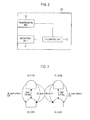
Fig. 2] Fig. 2 is a functional block diagram of a mobile station according to the first embodiment of the present invention. - [
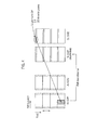
Fig. 3] Fig. 3 is a diagram for explaining the mapping of downlink CC and uplink CC in the mobile communication system according to the first embodiment of the present invention. - [
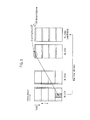
Fig. 4] Fig. 4 is a diagram for explaining a CA communication performed in the mobile communication system according to the first embodiment of the present invention. - [
Fig. 5] Fig. 5 is a diagram for explaining the CA communication performed in the mobile communication system according to the first embodiment of the present invention. - [
Fig. 6] Fig. 6 is a flowchart illustrating an operation of the mobile station according to the first embodiment of the present invention. - [
Fig. 7] Fig. 7 is a diagram for explaining a conventional mobile communication system. - A description will now be provided for the configuration of a mobile communication system according to a first embodiment of the present invention, with reference to
Fig. 1 to Fig. 6 . - The mobile communication system according to the present embodiment is an LTE-Advanced mobile communication system, and in the mobile communication system according to the present embodiment, a mobile station UE is configured to be able to perform a CA communication with a radio base station eNB by using a plurality of CCs having different carrier frequencies.
- As illustrated in
Fig. 1 , in the mobile communication system according to the present embodiment, the mobile station UE is configured to transmit an uplink data signal through PUSCH (Physical Uplink Shared Channel, an uplink shared channel), and to transmit an uplink control signal through PUCCH (Physical Uplink Control Channel, an uplink control channel). - Furthermore, in the mobile communication system according to the present embodiment, the radio base station eNB is configured to transmit a downlink data signal through PDSCH (Physical Downlink Shared Channel, a downlink shared channel), and to transmit a downlink control signal through PDCCH (Physical Downlink Control Channel, a downlink control channel).
- Furthermore, in the mobile communication system according to the present embodiment, the mobile station UE is configured to perform a CA communication by using
UL CC# 1, ULCC# 2, DLCC# 1, and DLCC# 2. - As illustrated in
Fig. 2 , the mobile station UE includes areception unit 11, atransmission unit 12, and aCA control unit 13. - The
reception unit 11 is configured to receive a downlink signal from the radio base station eNB through the PDSCH and the PDCCH. - The
transmission unit 12 is configured to transmit an uplink signal to the radio base station eNB through the PUSCH and the PUCCH. - The
CA control unit 13 is configured to control the CA communication performed by the mobile station UE. - For example, when the mobile station UE is performing the CA communication, the
CA control unit 12 is configured to be able to newly add CC, delete existing CC, or change PCC (Primary Component Carrier) on an RRC layer according to an indication (specifically, an RRC message) from the radio base station eNB. - Furthermore, when the mobile station UE is performing the CA communication, the
CA control unit 13 is configured to set a state (an active state or a deactive state) of each CC, which is used in the CA communication, on a MAC layer according to an indication (specifically, "MAC Control Element") from the radio base station eNB. - Furthermore, when the
reception unit 11 received "UL grant" for permitting the mobile station UE to transmit an uplink data signal in particular UL CC from the radio base station eNB through PDCCH in particular DL CC, thetransmission unit 12 is configured to transmit the uplink data signal through PUSCH in the particular UL CC. - In an example of
Fig. 3 , the radio base station eNB notifies information (SIB2 Linking) for correlating theUL CC# 1 with theDL CC# 1 and information (SIB2 Linking) for correlating theUL CC# 2 with theDL CC# 2 by SIB (System Information Block) 2. - In such a case, when the
reception unit 11 received "UL grant" with no CIF (Carrier Indicator Field) from the radio base station eNB through PDCCH in theDL CC# 1/#2, thetransmission unit 12 is configured to transmit the uplink data signal through PUSCH in theUL CC# 1/#2 corresponding to theDL CC# 1/#2. - Meanwhile, when the
reception unit 11 received "UL grant" with the CIF from the radio base station eNB through the PDCCH in theDL CC# 1/#2, thetransmission unit 12 is configured to transmit the uplink data signal through the PUSCH in theUL CC# 1/#2 indicated by the CIF. - Furthermore, as illustrated in
Fig. 4 , when thereception unit 11 received the "UL grant" for permitting the mobile station UE to transmit the uplink data signal in theUL CC# 1 from the radio base station eNB through the PDCCH in theDL CC# 2, that is, the "UL grant" with the CIF indicating theUL CC# 1, and when transmission power of theUL CC# 1 is controlled on the basis of path loss estimated from theDL CC# 1 in a deactive state, thetransmission unit 12 is configured to discard (that is, ignore) the "UL grant". - Moreover, as illustrated in
Fig. 5 , when theDL CC# 1 is correlated with theUL CC# 1 by the SIB2 Linking, when thereception unit 11 received the "UL grant" with no CIF from the radio base station eNB through theDL CC# 1, and when the transmission power of theUL CC# 1 is controlled on the basis of path loss estimated from theDL CC# 2 in a deactive state, thetransmission unit 12 is configured to discard (that is, ignore) the "UL grant". - In addition, in the above, the case in which the mobile station UE receives the "UL grant" through the PDCCH also includes a case in which the mobile station UE erroneously detects the "UL grant" although the PDCCH (the "UL grant") was not actually transmitted to the mobile station UE from the radio base station eNB.
- Specifically, the PDCCH (the "UL grant") is provided with an error detection bit sequence (a CRC bit sequence) masked by a mobile station UE-specific identifier (C-RNTI) for permitting the transmission of the uplink data signal through the PUSCH, and when it is determined that an inspection result based on a CRC bit sequence unmasked by the C-RNTI, which was assigned to the mobile station UE, of the received PDCCH (the "UL grant") is "OK", the mobile station UE detects that the PDCCH (the "UL grant") was assigned to the mobile station UE. However, the aforementioned case also includes a case in which the mobile station UE erroneously determines the inspection result based on the CRC bit sequence of the PDCCH (the "UL grant") as "OK" although the PDCCH (the "UL grant") was not actually transmitted to the mobile station UE from the radio base station eNB.
- A description will now be provided for the operation of the mobile station UE in the mobile communication system according to the present embodiment, with reference to
Fig. 6 . - As illustrated in
Fig. 6 , when "UL grant" for permitting the transmission of an uplink data signal in particular UL CC is received in step S101, the mobile station UE determines whether transmission power of the particular UL CC is controlled on the basis of path loss estimated from DL CC in a deactive state in step S102. - When it is determined that the transmission power of the particular UL CC is controlled on the basis of the path loss estimated from the DL CC in the deactive state, the mobile station UE discards (or ignores) the "UL grant" in step S103.
- Meanwhile, when it is determined that the transmission power of the particular UL CC is controlled on the basis of path loss estimated from DL CC in an active state, the mobile station UE transmits the uplink data signal to the radio base station eNB through PUSCH on the basis of the "UL grant" in step S103.
- In accordance with the mobile communication system according to the present embodiment, it is possible for the mobile station UE to stop the transmission of an uplink data signal in UL CC, and thus it is possible to avoid unnecessary interference, wherein the transmission power of the UL CC is controlled on the basis of path loss estimated from DL CC in a deactive state.
- The characteristics of the present embodiment as described above may be expressed as follows.
- A first characteristic of the present embodiment is summarized in that a mobile communication method, in which a mobile station UE performs a CA communication with a radio base station eNB by using a plurality of DL CCs (downlink carriers) and a plurality of UL CCs (uplink carriers) which have carrier frequencies different from each other, includes: a step A of receiving, by the mobile station UE, "UL grant (a scheduling signal)" for permitting the mobile station UE to transmit an uplink data signal in UL CC#1 (a predetermined uplink carrier) through PDCCH (a physical downlink control channel) in DL CC#2 (a first downlink carrier); and a step B of discarding, by the mobile station UE, the "UL grant" when transmission power of the
UL CC# 1 is controlled on the basis of path loss estimated from DL CC#1 (a second downlink carrier) in a deactive state. - In the first characteristic of the present embodiment, in the step A, the mobile station UE may receive CIF (a carrier indicator) indicating the
UL CC# 1 together with the "UL grant". - In the first characteristic of the present embodiment, the mobile communication method may include a step of notifying, by the radio base station eNB, the mobile station UE of information for correlating the
UL CC# 1 with theDL CC# 2 by broadcast information (SIB2). - A second characteristic of the present embodiment is summarized in that a mobile station UE, which is configured to be able to perform a CA communication with a radio base station eNB by using a plurality of DL CCs and a plurality of UL CCs which have carrier frequencies different from each other, includes: a
reception unit 11 configured to receive "UL grant" for permitting the mobile station UE to transmit an uplink data signal in ULCC# 1 through PDCCH in DLCC# 2, wherein, when transmission power of theUL CC# 1 is controlled on the basis of path loss estimated fromDL CC# 1 in a deactive state, thereception unit 11 is configured to discard the "UL grant". - Note that the operation of the mobile station UE or the radio base station eNB may be performed by hardware, a software module performed by a processor, or a combination of the both.
- The software module may be arranged in a storage medium of an arbitrary format such as a RAM (Random Access Memory), a flash memory, a ROM (Read Only Memory), an EPROM (Erasable Programmable ROM), an EEPROM (Electronically Erasable and Programmable ROM), a register, a hard disk, a removable disk, or a CD-ROM.
- The storage medium is connected to the processor so that the processor can write and read information into and from the storage medium. Such a storage medium may also be accumulated in the processor. Such a storage medium and processor may be arranged in an ASIC. The ASIC may be arranged in the mobile station UE or the radio base station eNB. Furthermore, such a storage medium and processor may be arranged in the mobile station UE or the radio base station eNB as discrete components.
- Thus, the present invention has been explained in detail by using the above-described embodiments; however, it is obvious that for persons skilled in the art, the present invention is not limited to the embodiments explained herein. The present invention can be implemented as a corrected and modified mode without departing the gist and the scope of the present invention defined by the claims. Therefore, the description of the specification is intended for explaining the example only and does not impose any limited meaning to the present invention.
- As described above, according to the present invention, it is possible to provide a mobile communication method and a mobile station, by which it is possible to reduce interference in a CA communication.
-
- eNB ...
- Radio base station
- UE ...
- Mobile station
- 11 ...
- Reception unit
- 12 ...
- Transmission unit
- 13 ...
- CA control unit
Claims (4)
- A mobile communication method, in which a mobile station communicates with a radio base station by using a plurality of downlink carriers and a plurality of uplink carriers, each of which has a different carrier frequency, the method comprising:a step A of receiving, by the mobile station, a scheduling signal for permitting the mobile station to transmit an uplink data signal in a predetermined uplink carrier through a physical downlink control channel in a first downlink carrier; anda step B of discarding, by the mobile station, the scheduling signal when transmission power of the predetermined uplink carrier is controlled on the basis of path loss estimated from a second downlink carrier in a deactive state.
- The mobile communication method according to claim 1, wherein, in the step A, the mobile station receives a carrier indicator indicating the predetermined uplink carrier together with the scheduling signal.
- The mobile communication method according to claim 1, further comprising: a step of notifying, by the radio base station, the mobile station of information for correlating the predetermined uplink carrier with the first downlink carrier by broadcast information.
- A mobile station configured to be capable of communicating with a radio base station by using a plurality of downlink carriers and a plurality of uplink carriers, each of which has a different carrier frequency, the mobile station comprising:a reception unit configured to receive a scheduling signal for permitting the mobile station to transmit an uplink data signal in a predetermined uplink carrier through a physical downlink control channel in a first downlink carrier, whereinwhen transmission power of the predetermined uplink carrier is controlled on the basis of path loss estimated from a second downlink carrier in a deactive state, the reception unit is configured to discard the scheduling signal.
Applications Claiming Priority (2)
| Application Number | Priority Date | Filing Date | Title |
|---|---|---|---|
| JP2010106008A JP4809487B1 (en) | 2010-04-30 | 2010-04-30 | Mobile communication method and mobile station |
| PCT/JP2011/060350 WO2011136314A1 (en) | 2010-04-30 | 2011-04-28 | Mobile communication method and mobile station |
Publications (2)
| Publication Number | Publication Date |
|---|---|
| EP2566276A1 true EP2566276A1 (en) | 2013-03-06 |
| EP2566276A4 EP2566276A4 (en) | 2015-04-22 |
Family
ID=44861610
Family Applications (1)
| Application Number | Title | Priority Date | Filing Date |
|---|---|---|---|
| EP11775095.0A Ceased EP2566276A4 (en) | 2010-04-30 | 2011-04-28 | MOBILE COMMUNICATION METHOD AND MOBILE STATION |
Country Status (8)
| Country | Link |
|---|---|
| US (1) | US8817721B2 (en) |
| EP (1) | EP2566276A4 (en) |
| JP (1) | JP4809487B1 (en) |
| KR (1) | KR101448694B1 (en) |
| CN (1) | CN102870484B (en) |
| AU (1) | AU2011246022B2 (en) |
| CA (1) | CA2797805C (en) |
| WO (1) | WO2011136314A1 (en) |
Families Citing this family (3)
| Publication number | Priority date | Publication date | Assignee | Title |
|---|---|---|---|---|
| JP5961282B2 (en) | 2011-12-22 | 2016-08-02 | インターデイジタル パテント ホールディングス インコーポレイテッド | Control signaling in LTE carrier aggregation |
| JP5846962B2 (en) * | 2012-02-27 | 2016-01-20 | 株式会社Nttドコモ | Mobile station |
| US10531512B2 (en) * | 2015-04-01 | 2020-01-07 | Huawei Technologies Co., Ltd. | System and method for a tracking channel |
Family Cites Families (10)
| Publication number | Priority date | Publication date | Assignee | Title |
|---|---|---|---|---|
| SE9300681D0 (en) * | 1993-03-01 | 1993-03-01 | Ericsson Telefon Ab L M | A METHOD AND APPARATUS FOR HANDING OFF A MOBILE STATION FROM A FIRST TO A SECOND CHANNEL IN A MOBILE COMMUNICATION SYSTEM |
| JP2762965B2 (en) * | 1995-09-04 | 1998-06-11 | 日本電気株式会社 | Base station transmission power control method |
| US6445917B1 (en) * | 1999-05-19 | 2002-09-03 | Telefonaktiebolaget Lm Ericsson (Publ) | Mobile station measurements with event-based reporting |
| US8249091B2 (en) * | 2009-10-21 | 2012-08-21 | Samsung Electronics Co., Ltd | Power headroom reporting method and device for wireless communication system |
| EP2360866A1 (en) * | 2010-02-12 | 2011-08-24 | Panasonic Corporation | Component carrier activation and deactivation using resource assignments |
| EP2360864A1 (en) * | 2010-02-12 | 2011-08-24 | Panasonic Corporation | Component carrier (de)activation in communication systems using carrier aggregation |
| AU2012294284A1 (en) * | 2011-08-11 | 2014-02-27 | Interdigital Patent Holdings, Inc. | Mobile relay handover |
| WO2013052805A1 (en) * | 2011-10-07 | 2013-04-11 | Interdigital Patent Holdings Inc. | Method and apparatus for integrating different radio access technologies using carrier aggregation |
| JP5961282B2 (en) * | 2011-12-22 | 2016-08-02 | インターデイジタル パテント ホールディングス インコーポレイテッド | Control signaling in LTE carrier aggregation |
| US8989042B2 (en) * | 2012-02-03 | 2015-03-24 | Mediatek Inc. | Method and apparatus for triggering and reporting diverse traffic information in cellular networks |
-
2010
- 2010-04-30 JP JP2010106008A patent/JP4809487B1/en not_active Expired - Fee Related
-
2011
- 2011-04-28 WO PCT/JP2011/060350 patent/WO2011136314A1/en not_active Ceased
- 2011-04-28 EP EP11775095.0A patent/EP2566276A4/en not_active Ceased
- 2011-04-28 KR KR1020127029193A patent/KR101448694B1/en not_active Expired - Fee Related
- 2011-04-28 AU AU2011246022A patent/AU2011246022B2/en not_active Ceased
- 2011-04-28 CA CA2797805A patent/CA2797805C/en active Active
- 2011-04-28 US US13/261,498 patent/US8817721B2/en active Active
- 2011-04-28 CN CN201180021779.XA patent/CN102870484B/en active Active
Non-Patent Citations (3)
| Title |
|---|
| NTT DOCOMO ET AL: "CC failure", 3GPP DRAFT; R2-102486, 3RD GENERATION PARTNERSHIP PROJECT (3GPP), MOBILE COMPETENCE CENTRE, vol. RAN WG2, 6 April 2010 (2010-04-06), pages 1-2, XP050422706, SOPHIA-ANTIPOLIS CEDEX ; FRANCE [retrieved on 2010-04-06] * |
| NTT DOCOMO ET AL: "DL and UL CC linkage for Carrier Aggregation", 3GPP DRAFT; R2-101534, 3RD GENERATION PARTNERSHIP PROJECT (3GPP), MOBILE COMPETENCE CENTRE, vol. RAN WG2, 16 February 2010 (2010-02-16), XP050421876, SOPHIA-ANTIPOLIS CEDEX ; FRANCE [retrieved on 2010-02-16] * |
| See also references of WO2011136314A1 * |
Also Published As
| Publication number | Publication date |
|---|---|
| WO2011136314A1 (en) | 2011-11-03 |
| AU2011246022A1 (en) | 2012-12-20 |
| KR20130016326A (en) | 2013-02-14 |
| CN102870484A (en) | 2013-01-09 |
| US20130077577A1 (en) | 2013-03-28 |
| AU2011246022B2 (en) | 2014-06-05 |
| CA2797805A1 (en) | 2011-11-03 |
| KR101448694B1 (en) | 2014-10-08 |
| JP2011238998A (en) | 2011-11-24 |
| JP4809487B1 (en) | 2011-11-09 |
| US8817721B2 (en) | 2014-08-26 |
| CN102870484B (en) | 2015-11-25 |
| EP2566276A4 (en) | 2015-04-22 |
| CA2797805C (en) | 2013-12-17 |
Similar Documents
| Publication | Publication Date | Title |
|---|---|---|
| AU2017240048B2 (en) | Sounding reference signal triggering for enhanced carrier aggregation | |
| US12484070B2 (en) | Carrier aggregation enhancements for new radio (NR) | |
| US10701565B2 (en) | Network node, method and computer program product for scheduling of paging messages with respect to discovery signal transmissions | |
| US11445451B2 (en) | Method and device for reporting channel state information | |
| EP2566231B1 (en) | Mobile communication method and mobile station | |
| US20170048880A1 (en) | Uplink resource scheduling control in response to channel busy condition | |
| US20160192361A1 (en) | Managing Sounding Signals to Limit Power in a Multicarrier Wireless Device | |
| JP6494862B2 (en) | First communication device and method therefor for transmitting one or more control signals to a second communication device | |
| EP2749112A1 (en) | Method for contention based random access on a secondary carrier | |
| US10687363B2 (en) | Mobile station | |
| US8817721B2 (en) | Mobile communication method and mobile station | |
| US10397885B2 (en) | Terminal that transmits reporting information and communication control method of transmitting reporting information in mobile communication system | |
| JP5487169B2 (en) | Mobile communication method and mobile station | |
| HK1252525B (en) | First communication device and methods therein, for sending one or more control signals to a second communication device | |
| KR20170112173A (en) | Method of perfoming a rate matching for uplink data transmition and appratus thereof |
Legal Events
| Date | Code | Title | Description |
|---|---|---|---|
| PUAI | Public reference made under article 153(3) epc to a published international application that has entered the european phase |
Free format text: ORIGINAL CODE: 0009012 |
|
| 17P | Request for examination filed |
Effective date: 20121120 |
|
| AK | Designated contracting states |
Kind code of ref document: A1 Designated state(s): AL AT BE BG CH CY CZ DE DK EE ES FI FR GB GR HR HU IE IS IT LI LT LU LV MC MK MT NL NO PL PT RO RS SE SI SK SM TR |
|
| DAX | Request for extension of the european patent (deleted) | ||
| RA4 | Supplementary search report drawn up and despatched (corrected) |
Effective date: 20150324 |
|
| RIC1 | Information provided on ipc code assigned before grant |
Ipc: H04W 52/16 20090101ALI20150318BHEP Ipc: H04L 5/00 20060101ALI20150318BHEP Ipc: H04W 72/14 20090101AFI20150318BHEP |
|
| 17Q | First examination report despatched |
Effective date: 20160120 |
|
| REG | Reference to a national code |
Ref country code: DE Ref legal event code: R003 |
|
| 18R | Application refused |
Effective date: 20170929 |