EP2566100A1 - Energy efficiency ethernet with low power active idle transmission mode - Google Patents
Energy efficiency ethernet with low power active idle transmission mode Download PDFInfo
- Publication number
- EP2566100A1 EP2566100A1 EP12005499A EP12005499A EP2566100A1 EP 2566100 A1 EP2566100 A1 EP 2566100A1 EP 12005499 A EP12005499 A EP 12005499A EP 12005499 A EP12005499 A EP 12005499A EP 2566100 A1 EP2566100 A1 EP 2566100A1
- Authority
- EP
- European Patent Office
- Prior art keywords
- idle
- mode
- active
- transmission mode
- low power
- Prior art date
- Legal status (The legal status is an assumption and is not a legal conclusion. Google has not performed a legal analysis and makes no representation as to the accuracy of the status listed.)
- Granted
Links
Images


Classifications
-
- H—ELECTRICITY
- H04—ELECTRIC COMMUNICATION TECHNIQUE
- H04L—TRANSMISSION OF DIGITAL INFORMATION, e.g. TELEGRAPHIC COMMUNICATION
- H04L12/00—Data switching networks
- H04L12/02—Details
- H04L12/12—Arrangements for remote connection or disconnection of substations or of equipment thereof
-
- H—ELECTRICITY
- H04—ELECTRIC COMMUNICATION TECHNIQUE
- H04L—TRANSMISSION OF DIGITAL INFORMATION, e.g. TELEGRAPHIC COMMUNICATION
- H04L65/00—Network arrangements, protocols or services for supporting real-time applications in data packet communication
-
- G—PHYSICS
- G06—COMPUTING OR CALCULATING; COUNTING
- G06F—ELECTRIC DIGITAL DATA PROCESSING
- G06F1/00—Details not covered by groups G06F3/00 - G06F13/00 and G06F21/00
- G06F1/26—Power supply means, e.g. regulation thereof
- G06F1/32—Means for saving power
- G06F1/3203—Power management, i.e. event-based initiation of a power-saving mode
- G06F1/3234—Power saving characterised by the action undertaken
- G06F1/325—Power saving in peripheral device
- G06F1/3278—Power saving in modem or I/O interface
-
- H—ELECTRICITY
- H04—ELECTRIC COMMUNICATION TECHNIQUE
- H04L—TRANSMISSION OF DIGITAL INFORMATION, e.g. TELEGRAPHIC COMMUNICATION
- H04L12/00—Data switching networks
- H04L12/02—Details
- H04L12/10—Current supply arrangements
-
- H—ELECTRICITY
- H04—ELECTRIC COMMUNICATION TECHNIQUE
- H04L—TRANSMISSION OF DIGITAL INFORMATION, e.g. TELEGRAPHIC COMMUNICATION
- H04L12/00—Data switching networks
- H04L12/28—Data switching networks characterised by path configuration, e.g. LAN [Local Area Networks] or WAN [Wide Area Networks]
- H04L12/40—Bus networks
- H04L12/40006—Architecture of a communication node
- H04L12/40039—Details regarding the setting of the power status of a node according to activity on the bus
-
- Y—GENERAL TAGGING OF NEW TECHNOLOGICAL DEVELOPMENTS; GENERAL TAGGING OF CROSS-SECTIONAL TECHNOLOGIES SPANNING OVER SEVERAL SECTIONS OF THE IPC; TECHNICAL SUBJECTS COVERED BY FORMER USPC CROSS-REFERENCE ART COLLECTIONS [XRACs] AND DIGESTS
- Y02—TECHNOLOGIES OR APPLICATIONS FOR MITIGATION OR ADAPTATION AGAINST CLIMATE CHANGE
- Y02D—CLIMATE CHANGE MITIGATION TECHNOLOGIES IN INFORMATION AND COMMUNICATION TECHNOLOGIES [ICT], I.E. INFORMATION AND COMMUNICATION TECHNOLOGIES AIMING AT THE REDUCTION OF THEIR OWN ENERGY USE
- Y02D10/00—Energy efficient computing, e.g. low power processors, power management or thermal management
-
- Y—GENERAL TAGGING OF NEW TECHNOLOGICAL DEVELOPMENTS; GENERAL TAGGING OF CROSS-SECTIONAL TECHNOLOGIES SPANNING OVER SEVERAL SECTIONS OF THE IPC; TECHNICAL SUBJECTS COVERED BY FORMER USPC CROSS-REFERENCE ART COLLECTIONS [XRACs] AND DIGESTS
- Y02—TECHNOLOGIES OR APPLICATIONS FOR MITIGATION OR ADAPTATION AGAINST CLIMATE CHANGE
- Y02D—CLIMATE CHANGE MITIGATION TECHNOLOGIES IN INFORMATION AND COMMUNICATION TECHNOLOGIES [ICT], I.E. INFORMATION AND COMMUNICATION TECHNOLOGIES AIMING AT THE REDUCTION OF THEIR OWN ENERGY USE
- Y02D30/00—Reducing energy consumption in communication networks
-
- Y—GENERAL TAGGING OF NEW TECHNOLOGICAL DEVELOPMENTS; GENERAL TAGGING OF CROSS-SECTIONAL TECHNOLOGIES SPANNING OVER SEVERAL SECTIONS OF THE IPC; TECHNICAL SUBJECTS COVERED BY FORMER USPC CROSS-REFERENCE ART COLLECTIONS [XRACs] AND DIGESTS
- Y02—TECHNOLOGIES OR APPLICATIONS FOR MITIGATION OR ADAPTATION AGAINST CLIMATE CHANGE
- Y02D—CLIMATE CHANGE MITIGATION TECHNOLOGIES IN INFORMATION AND COMMUNICATION TECHNOLOGIES [ICT], I.E. INFORMATION AND COMMUNICATION TECHNOLOGIES AIMING AT THE REDUCTION OF THEIR OWN ENERGY USE
- Y02D30/00—Reducing energy consumption in communication networks
- Y02D30/50—Reducing energy consumption in communication networks in wire-line communication networks, e.g. low power modes or reduced link rate
Definitions
- the present invention relates generally to energy efficient Ethernet networks and, more particularly, to energy efficient Ethernet with a low power active idle transmission mode.
- one of the considerations is the utilization of the network link.
- many network links are typically in an idle state between sporadic bursts of data. During this idle state, idle signals are transmitted. Unfortunately, the transmission of idle signals wastes energy and adds to the radiated emission levels.
- An energy efficient Ethernet with a low power active idle transmission mode substantially as shown in and/or described in connection with at least one of the figures, as set forth more completely in the claims.
- an energy efficiency method is provided in a physical layer device, comprising:
- the method further comprises transitioning from said active idle transmission mode to said active data transmission mode when data traffic is ready for transmission.
- said active idle transmission mode uses a different signal constellation than said active data transmission mode.
- said transitioning comprises transitioning from said active data transmission mode to said low power idle mode.
- said transitioning comprises transitioning from said active idle transmission mode to said low power idle mode.
- the method further comprises transmitting refresh signals during said low power idle mode.
- an energy efficient physical layer device comprises:
- said active idle data transmission mode uses a different signal constellation than said active data transmission mode.
- one or more parts of said transceiver are switched off when in said active idle data transmission mode.
- an energy efficiency method in a physical layer device having a low power mode used during periods of low link utilization, comprising:
- the method further comprises transitioning from said active idle transmission mode to said active data transmission mode when data traffic is ready for transmission.
- said active idle transmission mode uses a different signal constellation than said active data transmission mode.
- the method further comprises transitioning from said active data transmission mode to said low power mode.
- the method further comprises transitioning from said active idle transmission mode to said low power mode.
- said low power mode is a low power idle mode.
- said low power mode uses subrating.
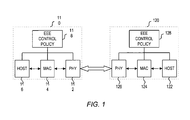
- FIG. 1 illustrates an Ethernet link between link partners.
- FIG. 2 illustrates transitions between an active mode and a low power idle mode.
- FIG. 3 illustrates transitions between an active data transmission mode and an active idle transmission mode.
- FIG. 4 illustrates a flowchart of a process of the present invention.
- Energy Efficient Ethernet networks attempt to save power when the traffic utilization of the network is not at its maximum capacity. This serves to minimize the performance impact while maximizing energy savings.
- the energy efficiency control policy for a particular link in the network determines when to enter an energy saving state, what energy saving state (i.e., level of energy savings) to enter, how long to remain in that energy saving state, what energy saving state to transition to out of the previous energy saving state, etc.
- energy efficiency control policies can base these energy-saving decisions on a combination of settings established by an IT manager and the properties of the traffic on the link itself.
- FIG. 1 illustrates an example link to which an energy efficiency control policy can be applied.
- the link supports communication between a first link partner 110 and a second link partner 120.
- link partners 110 and 120 can represent a switch, router, endpoint (e.g., server, client, VOIP phone, wireless access point, etc.), or the like.
- link partner 110 includes physical layer device (PHY) 112, media access control (MAC) 114, and host 116
- link partner 120 includes PHY 122, MAC 124, and host 126.
- PHY physical layer device
- MAC media access control
- hosts 116 and 126 may comprise suitable logic, circuitry, and/or code that may enable operability and/or functionality of the five highest functional layers for data packets that are to be transmitted over the link. Since each layer in the OSI model provides a service to the immediately higher interfacing layer, MAC controllers 114 and 124 may provide the necessary services to hosts 116 and 126 to ensure that packets are suitably formatted and communicated to PHYs 112 and 122, respectively. MAC controllers 114 and 124 may comprise suitable logic, circuitry, and/or code that may enable handling of data link layer (Layer 2) operability and/or functionality. MAC controllers 114 and 124 can be configured to implement Ethernet protocols, such as those based on the IEEE 802.3 standard, for example. PHYs 112 and 122 can be configured to handle physical layer requirements, which include, but are not limited to, packetization, data transfer and serialization/deserialization (SERDES).
- SERDES serialization/deserialization
- link partners 110 and 120 also include energy efficiency control policy entities 118 and 128, respectively.
- energy efficiency control policy entities 118 and 128 can be designed to determine when to enter an energy saving state, what energy saving state (i.e., level of energy savings) to enter, how long to remain in that energy saving state, what energy saving state to transition to out of the previous energy saving state, etc.
- energy efficiency control policy entities 118 and 128 can comprise suitable logic, circuitry, and/or code that may be enabled to establish and/or implement an energy efficiency control policy for the network device.
- energy efficiency control policy entities 118 and 128 can be a logical and/or functional block which may, for example, be implemented in one or more layers, including portions of the PHY or enhanced PHY, MAC, switch, controller, or other subsystems in the host, thereby enabling energy-efficiency control at one or more layers.
- energy efficient Ethernet such as that defined by IEEE 802.3az can provide substantial energy savings through the use of a low power idle mode and/or subrating.
- the low power idle mode can be entered when a transmitter enters a period of silence when there is no data to be sent.
- subrating can be used to address low link utilization conditions.
- FIG. 2 illustrates the transitions between an active mode and a low power idle mode.
- a transmitter can begin in an active mode where data traffic and idle signals are transmitted.
- the energy efficiency control policy can then instruct the transmitter to enter into a low power idle mode.
- a transition from an active mode to the low power idle mode takes a sleep time T s , after which time the transmitter can enter a quiet state.
- the transmitter can stay quiet for a time T q , after which the transmitter will transmit a refresh signal.
- refresh signals are sent periodically to keep the link alive and to enable the receiver to maintain synchronization.
- the transmitter can remain in a quiet state until data traffic is ready to be transmitted. Significant energy savings can be achieved while in the quiet state.
- a normal idle signal is used to wake the transmit system up before the data traffic can be sent.
- the transmitter can take a time T w to wake up and re-enter the active mode once again for transmission of data traffic that is available.
- the low power idle mode enables substantial energy savings.
- One of the tradeoffs in leveraging the low power idle mode is the overhead represented by the wake time (T w ) and the sleep time (T s ). These overhead times in transitioning to and from the low power idle mode can take microseconds.
- the overhead times represented by the wake time (T w ) and the sleep time (T s ) do not represent a severe penalty. This is the case because the transition times between the active mode and the low power idle mode are a small percentage of the length of time during which the link is inactive.
- Some traffic profiles may have inter-packet gaps (IPGs) that are broken up into smaller durations that can be comparable in duration to the transition times represented by the low power idle wake time (T w ) and sleep time (T s ).
- IPGs inter-packet gaps
- T w low power idle wake time
- T s sleep time
- the result of this type of traffic profile can be significantly degraded efficiency. This degraded efficiency can result simply because the system is able to enter the low power idle mode much less frequently. Additionally, degraded efficiency can result because the system enters and immediately leaves the low power idle mode without any significant energy savings. As would be appreciated, the entry and exit from the low power idle mode will incur power and performance (e.g., latency) costs.
- the level of energy savings gained by the low power idle mode are dependent and highly sensitive to the traffic profile.
- the traffic profiles are not known a priori.
- One potential solution to traffic profiles that have small IPGs is to buffer and batch the data traffic. This potential solution is not ideal, however, because buffering can be expensive. For this and other reasons, industry trends are moving away from such buffering implementations. Even if buffer and batch techniques are available, some traffic profiles cannot be significantly modified because the traffic (e.g., control traffic) cannot be significantly delayed.
- the low power idle mode can produce significant energy savings in certain low-link utilization conditions. It is therefore a feature of the present invention that the low power idle mode can be complemented by an energy savings mechanism that can be utilized during the active mode. This active-mode mechanism can then be leveraged to produce energy savings on a link even when the traffic profile does not lend itself to energy savings produced by the low power idle mode. As will become apparent by the description below, this complementary energy savings technique would not require a modification of the traffic profile.
- the complementary energy savings mechanism is designed to save energy during the transmission of idle signals during the active mode.
- the energy consumed by the transmission of idle signals during the active mode is similar to the energy consumed by the transmission of data traffic during the active mode.
- energy savings can be achieved during normal idle signaling by taking advantage of the inherently improved noise and error tolerance during idle signaling in the active mode.
- a low power active idle signal transmission during an active mode can be defined that is capable of very fast (or zero) transition time between an active data transmission mode and a low power active idle transmission mode.
- the low power active idle transmission mode can be enabled when the link utilization is less than 100% but greater than the utilization level that would ordinarily trigger a low power idle mode. As such the low power active idle transmission mode would complement the low power idle mode in providing energy savings in those traffic profile instances that would preclude the use of the low power idle mode.
- FIGS. 3 and 4 illustrate the complementary use of such a low power active idle transmission mode.
- the process begins at step 402 where a transmitter transmits data traffic and idle signals while in an active data transmission mode.
- the energy efficiency control policy would analyze the link utilization to determine whether the absence of data traffic indicates the potential to achieve energy savings.
- an energy efficiency control policy can determine at step 406 whether the link utilization drops below a determined threshold.
- multiple thresholds relating to one or more link utilization measures can be used to distinguish between two or more energy savings states.
- a first threshold can be used to identify the applicability of the active idle transmission mode for a first level of energy savings
- a second threshold can be used to identify a deeper level of energy savings represented by the low power idle mode.
- the energy efficiency control policy can adjust the one or more thresholds based on the latency requirements of the energy efficiency control policy and the energy efficiency capabilities of the device.
- the link utilization level may be below the first threshold, yet above the second threshold, thereby precluding the entry into the low power idle mode.
- step 406 If it is determined at step 406 that the link utilization is not below the first threshold, then the transmit system would remain in the active data transmission mode. If, on the other hand, it is determined at step 406 that the link utilization is below the first threshold, then the transmit system would transmit idle signals in an active idle transmission mode at step 408, thereby producing some energy savings.
- the low power active idle transmission mode can use normal idle signaling where certain functions within the physical layer device can be placed in a low power mode. For example, in a 10G physical layer device portions of a pre-emphasis module can be powered off due to the inherently improved noise and error tolerance during the transmission of idle signals in an active mode.
- the low power active idle transmission mode can be based on a different signal constellation. For example, a gigabit Ethernet transmitter can transition from PAM-5 modulation for the transmission of data traffic, to the more impairment-tolerant PAM-3 modulation for the transmission of idle signals.
- some performance degradation would be acceptable because idle signals are inherently more tolerant of performance degradation and. Additionally, bit errors are not as critical. More generally, the low power active idle transmission mode can take advantage of the fact that reduced performance is acceptable.
- the low power active idle transmission mode can be defined such that little to no transition times would be required. As such, the low power active idle transmission mode would be suitable for use in those instances where the IPGs are short in duration and the low power idle mode would not apply. As illustrated in FIG. 3 , the low power active idle mode can be used up until the point in time that the energy efficiency control policy indicates that the low power idle mode can be entered. At that point in time, deeper energy savings can be achieved through the low power idle mode.
- transitions between the active data transmission mode, active idle transmission mode, and low power idle mode need not be strictly sequential.
- the energy efficiency policy can be designed to transition from the active data transmission mode directly to the low power idle mode, thereby bypassing the active idle transmission mode. This scenario can result, for example, where the low power idle mode is preferred and entry into the active idle transmission mode is dependent on a failure to enter into the low power idle mode.
- the active idle transmission mode In the present invention it is recognized that the particular relationship between the active idle transmission mode and the low power idle mode would be implementation dependent. What is significant is that the active idle transmission mode can be called upon to produce energy savings in instances that would preclude the application of the low power idle mode. It is also significant that the usage of the lower power active idle transmission mode need not be dependent on the link partner.
Landscapes
- Engineering & Computer Science (AREA)
- Computer Networks & Wireless Communication (AREA)
- Signal Processing (AREA)
- Theoretical Computer Science (AREA)
- Physics & Mathematics (AREA)
- General Engineering & Computer Science (AREA)
- General Physics & Mathematics (AREA)
- Multimedia (AREA)
- Small-Scale Networks (AREA)
- Mobile Radio Communication Systems (AREA)
- Communication Control (AREA)
- Power Sources (AREA)
Abstract
Description
- The present invention relates generally to energy efficient Ethernet networks and, more particularly, to energy efficient Ethernet with a low power active idle transmission mode.
- Energy costs continue to escalate in a trend that has accelerated in recent years. Such being the case, various industries have become increasingly sensitive to the impact of those rising costs. One area that has drawn increasing scrutiny is the IT infrastructure. Many companies are now looking at their IT systems' power usage to determine whether the energy costs can be reduced. For this reason, an industry focus on energy efficient networks has arisen to address the rising costs of IT equipment usage as a whole (i.e., PCs, displays, printers, servers, network equipment, etc.).
- In designing an energy efficient solution, one of the considerations is the utilization of the network link. For example, many network links are typically in an idle state between sporadic bursts of data. During this idle state, idle signals are transmitted. Unfortunately, the transmission of idle signals wastes energy and adds to the radiated emission levels.
- While identification of low link utilization periods can provide opportunities to produce energy savings, many traffic profiles can include regular or intermittent low-bandwidth traffic, with bursts of high-bandwidth traffic. Here, identification of a low link utilization period is more difficult and the potential for energy savings is reduced. What is needed therefore is a mechanism that can produce energy savings during active idle signal transmissions.
- An energy efficient Ethernet with a low power active idle transmission mode, substantially as shown in and/or described in connection with at least one of the figures, as set forth more completely in the claims.
- According to an aspect of the invention, an energy efficiency method is provided in a physical layer device, comprising:
- transmitting data traffic using an active data transmission mode of said physical layer device;
- transmitting idle signals when data traffic is not available for transmission, said transmission of idle signals using an idle transmission mode that consumes less power than transmission using said active data transmission mode; and
- transitioning to a low power idle mode based on an indication of low link utilization, said low power idle mode conserving energy through a deactivation of transmitter or receiver components in said physical layer device.
- Advantageously, the method further comprises transitioning from said active idle transmission mode to said active data transmission mode when data traffic is ready for transmission.
- Advantageously, said active idle transmission mode uses a different signal constellation than said active data transmission mode.
- Advantageously, said transitioning comprises transitioning from said active data transmission mode to said low power idle mode.
- Advantageously, said transitioning comprises transitioning from said active idle transmission mode to said low power idle mode.
- Advantageously, the method further comprises transmitting refresh signals during said low power idle mode.
- According to an aspect, an energy efficient physical layer device comprises:
- a transceiver, said transceiver having one or more components that are turned off during a low power idle mode of said physical layer device, said low power idle mode of said physical layer device including sleep, quiet, refresh and wake states; and
- a controller that controls an operation of said transceiver while in an active mode for a communication of data traffic and idle signals, said controller being configured to transition said transceiver from an active data transmission mode used for the transmission of data traffic to an active idle data transmission mode used for a transmission of idle signals, said active idle data transmission mode consuming less power than said active data transmission mode and more power than said low power idle mode.
- Advantageously, said active idle data transmission mode uses a different signal constellation than said active data transmission mode.
- Advantageously, one or more parts of said transceiver are switched off when in said active idle data transmission mode.
- According to an aspect, an energy efficiency method is provided in a physical layer device having a low power mode used during periods of low link utilization, comprising:
- transmitting data traffic using an active data transmission mode of said physical layer device; and
- during an inter-packet gap, transitioning said physical layer device to an active idle transmission mode for a transmission of idle signals during said inter-packet gap, said active idle transmission mode consuming less power than said active data transmission mode and more power than said low power mode.
- Advantageously, the method further comprises transitioning from said active idle transmission mode to said active data transmission mode when data traffic is ready for transmission.
- Advantageously, said active idle transmission mode uses a different signal constellation than said active data transmission mode.
- Advantageously, the method further comprises transitioning from said active data transmission mode to said low power mode.
- Advantageously, the method further comprises transitioning from said active idle transmission mode to said low power mode.
- Advantageously, said low power mode is a low power idle mode.
- Advantageously, said low power mode uses subrating.
- In order to describe the manner in which the above-recited and other advantages and features of the invention can be obtained, a more particular description of the invention briefly described above will be rendered by reference to specific embodiments thereof which are illustrated in the appended drawings. Understanding that these drawings depict only typical embodiments of the invention and are not therefore to be considered limiting of its scope, the invention will be described and explained with additional specificity and detail through the use of the accompanying drawings in which:
-
FIG. 1 illustrates an Ethernet link between link partners. -
FIG. 2 illustrates transitions between an active mode and a low power idle mode. -
FIG. 3 illustrates transitions between an active data transmission mode and an active idle transmission mode. -
FIG. 4 illustrates a flowchart of a process of the present invention. - Various embodiments of the invention are discussed in detail below. While specific implementations are discussed, it should be understood that this is done for illustration purposes only. A person skilled in the relevant art will recognize that other components and configurations may be used without parting from the spirit and scope of the invention.
- Energy Efficient Ethernet networks attempt to save power when the traffic utilization of the network is not at its maximum capacity. This serves to minimize the performance impact while maximizing energy savings. At a broad level, the energy efficiency control policy for a particular link in the network determines when to enter an energy saving state, what energy saving state (i.e., level of energy savings) to enter, how long to remain in that energy saving state, what energy saving state to transition to out of the previous energy saving state, etc. In one embodiment, energy efficiency control policies can base these energy-saving decisions on a combination of settings established by an IT manager and the properties of the traffic on the link itself.
-
FIG. 1 illustrates an example link to which an energy efficiency control policy can be applied. As illustrated, the link supports communication between a first link partner 110 and asecond link partner 120. In various embodiments,link partners 110 and 120 can represent a switch, router, endpoint (e.g., server, client, VOIP phone, wireless access point, etc.), or the like. As illustrated, link partner 110 includes physical layer device (PHY) 112, media access control (MAC) 114, and host 116, whilelink partner 120 includes PHY 122, MAC 124, andhost 126. - In general,
hosts 116 and 126 may comprise suitable logic, circuitry, and/or code that may enable operability and/or functionality of the five highest functional layers for data packets that are to be transmitted over the link. Since each layer in the OSI model provides a service to the immediately higher interfacing layer,MAC controllers 114 and 124 may provide the necessary services to hosts 116 and 126 to ensure that packets are suitably formatted and communicated toPHYs 112 and 122, respectively.MAC controllers 114 and 124 may comprise suitable logic, circuitry, and/or code that may enable handling of data link layer (Layer 2) operability and/or functionality.MAC controllers 114 and 124 can be configured to implement Ethernet protocols, such as those based on the IEEE 802.3 standard, for example.PHYs 112 and 122 can be configured to handle physical layer requirements, which include, but are not limited to, packetization, data transfer and serialization/deserialization (SERDES). - As
FIG. 1 further illustrates,link partners 110 and 120 also include energy efficiencycontrol policy entities 118 and 128, respectively. In general, energy efficiencycontrol policy entities 118 and 128 can be designed to determine when to enter an energy saving state, what energy saving state (i.e., level of energy savings) to enter, how long to remain in that energy saving state, what energy saving state to transition to out of the previous energy saving state, etc. - In general, energy efficiency
control policy entities 118 and 128 can comprise suitable logic, circuitry, and/or code that may be enabled to establish and/or implement an energy efficiency control policy for the network device. In various embodiments, energy efficiencycontrol policy entities 118 and 128 can be a logical and/or functional block which may, for example, be implemented in one or more layers, including portions of the PHY or enhanced PHY, MAC, switch, controller, or other subsystems in the host, thereby enabling energy-efficiency control at one or more layers. - In one example, energy efficient Ethernet such as that defined by IEEE 802.3az can provide substantial energy savings through the use of a low power idle mode and/or subrating. In general, the low power idle mode can be entered when a transmitter enters a period of silence when there is no data to be sent. More generally, subrating can be used to address low link utilization conditions.
-
FIG. 2 illustrates the transitions between an active mode and a low power idle mode. As illustrated, a transmitter can begin in an active mode where data traffic and idle signals are transmitted. When it is determined by an energy efficiency control policy that the absence of data traffic indicates a sufficiently low link utilization condition, the energy efficiency control policy can then instruct the transmitter to enter into a low power idle mode. A transition from an active mode to the low power idle mode takes a sleep time Ts, after which time the transmitter can enter a quiet state. The transmitter can stay quiet for a time Tq, after which the transmitter will transmit a refresh signal. In general, refresh signals are sent periodically to keep the link alive and to enable the receiver to maintain synchronization. The transmitter can remain in a quiet state until data traffic is ready to be transmitted. Significant energy savings can be achieved while in the quiet state. - When there is data to transmit, a normal idle signal is used to wake the transmit system up before the data traffic can be sent. As illustrated, the transmitter can take a time Tw to wake up and re-enter the active mode once again for transmission of data traffic that is available.
- The low power idle mode enables substantial energy savings. One of the tradeoffs in leveraging the low power idle mode is the overhead represented by the wake time (Tw) and the sleep time (Ts). These overhead times in transitioning to and from the low power idle mode can take microseconds.
- Where the traffic profile is truly burst-like (e.g., link is inactive for 90% or more of the time), the overhead times represented by the wake time (Tw) and the sleep time (Ts) do not represent a severe penalty. This is the case because the transition times between the active mode and the low power idle mode are a small percentage of the length of time during which the link is inactive.
- Some traffic profiles, however, may have inter-packet gaps (IPGs) that are broken up into smaller durations that can be comparable in duration to the transition times represented by the low power idle wake time (Tw) and sleep time (Ts). The result of this type of traffic profile can be significantly degraded efficiency. This degraded efficiency can result simply because the system is able to enter the low power idle mode much less frequently. Additionally, degraded efficiency can result because the system enters and immediately leaves the low power idle mode without any significant energy savings. As would be appreciated, the entry and exit from the low power idle mode will incur power and performance (e.g., latency) costs.
- The level of energy savings gained by the low power idle mode are dependent and highly sensitive to the traffic profile. Unfortunately, the traffic profiles are not known a priori. One potential solution to traffic profiles that have small IPGs is to buffer and batch the data traffic. This potential solution is not ideal, however, because buffering can be expensive. For this and other reasons, industry trends are moving away from such buffering implementations. Even if buffer and batch techniques are available, some traffic profiles cannot be significantly modified because the traffic (e.g., control traffic) cannot be significantly delayed.
- Notwithstanding these drawbacks, the low power idle mode can produce significant energy savings in certain low-link utilization conditions. It is therefore a feature of the present invention that the low power idle mode can be complemented by an energy savings mechanism that can be utilized during the active mode. This active-mode mechanism can then be leveraged to produce energy savings on a link even when the traffic profile does not lend itself to energy savings produced by the low power idle mode. As will become apparent by the description below, this complementary energy savings technique would not require a modification of the traffic profile.
- In one embodiment, the complementary energy savings mechanism is designed to save energy during the transmission of idle signals during the active mode. As noted above, the energy consumed by the transmission of idle signals during the active mode is similar to the energy consumed by the transmission of data traffic during the active mode. In the present invention, it is recognized that energy savings can be achieved during normal idle signaling by taking advantage of the inherently improved noise and error tolerance during idle signaling in the active mode.
- It is a feature of the present invention that a low power active idle signal transmission during an active mode can be defined that is capable of very fast (or zero) transition time between an active data transmission mode and a low power active idle transmission mode. In general, the low power active idle transmission mode can be enabled when the link utilization is less than 100% but greater than the utilization level that would ordinarily trigger a low power idle mode. As such the low power active idle transmission mode would complement the low power idle mode in providing energy savings in those traffic profile instances that would preclude the use of the low power idle mode.
-
FIGS. 3 and4 illustrate the complementary use of such a low power active idle transmission mode. As illustrated, the process begins atstep 402 where a transmitter transmits data traffic and idle signals while in an active data transmission mode. Atstep 404, the energy efficiency control policy would analyze the link utilization to determine whether the absence of data traffic indicates the potential to achieve energy savings. As idle signals are transmitted and the link utilization level drops, an energy efficiency control policy can determine atstep 406 whether the link utilization drops below a determined threshold. - In the present invention it is recognized that multiple thresholds relating to one or more link utilization measures can be used to distinguish between two or more energy savings states. In the example where an active idle transmission mode and a low power idle mode are used as two different energy savings states, a first threshold can be used to identify the applicability of the active idle transmission mode for a first level of energy savings, while a second threshold can be used to identify a deeper level of energy savings represented by the low power idle mode. More generally, it should be noted that the energy efficiency control policy can adjust the one or more thresholds based on the latency requirements of the energy efficiency control policy and the energy efficiency capabilities of the device.
- As noted, smaller IPGs may preclude the use of a low power idle mode. In these instances, the link utilization level may be below the first threshold, yet above the second threshold, thereby precluding the entry into the low power idle mode.
- If it is determined at
step 406 that the link utilization is not below the first threshold, then the transmit system would remain in the active data transmission mode. If, on the other hand, it is determined atstep 406 that the link utilization is below the first threshold, then the transmit system would transmit idle signals in an active idle transmission mode atstep 408, thereby producing some energy savings. - In one embodiment, the low power active idle transmission mode can use normal idle signaling where certain functions within the physical layer device can be placed in a low power mode. For example, in a 10G physical layer device portions of a pre-emphasis module can be powered off due to the inherently improved noise and error tolerance during the transmission of idle signals in an active mode. In another embodiment, the low power active idle transmission mode can be based on a different signal constellation. For example, a gigabit Ethernet transmitter can transition from PAM-5 modulation for the transmission of data traffic, to the more impairment-tolerant PAM-3 modulation for the transmission of idle signals. Here, some performance degradation would be acceptable because idle signals are inherently more tolerant of performance degradation and. Additionally, bit errors are not as critical. More generally, the low power active idle transmission mode can take advantage of the fact that reduced performance is acceptable.
- As noted, the low power active idle transmission mode can be defined such that little to no transition times would be required. As such, the low power active idle transmission mode would be suitable for use in those instances where the IPGs are short in duration and the low power idle mode would not apply. As illustrated in
FIG. 3 , the low power active idle mode can be used up until the point in time that the energy efficiency control policy indicates that the low power idle mode can be entered. At that point in time, deeper energy savings can be achieved through the low power idle mode. - It should be noted that transitions between the active data transmission mode, active idle transmission mode, and low power idle mode need not be strictly sequential. For example, the energy efficiency policy can be designed to transition from the active data transmission mode directly to the low power idle mode, thereby bypassing the active idle transmission mode. This scenario can result, for example, where the low power idle mode is preferred and entry into the active idle transmission mode is dependent on a failure to enter into the low power idle mode.
- In the present invention it is recognized that the particular relationship between the active idle transmission mode and the low power idle mode would be implementation dependent. What is significant is that the active idle transmission mode can be called upon to produce energy savings in instances that would preclude the application of the low power idle mode. It is also significant that the usage of the lower power active idle transmission mode need not be dependent on the link partner.
- These and other aspects of the present invention will become apparent to those skilled in the art by a review of the preceding detailed description. Although a number of salient features of the present invention have been described above, the invention is capable of other embodiments and of being practiced and carried out in various ways that would be apparent to one of ordinary skill in the art after reading the disclosed invention, therefore the above description should not be considered to be exclusive of these other embodiments. Also, it is to be understood that the phraseology and terminology employed herein are for the purposes of description and should not be regarded as limiting.
Claims (15)
- An energy efficiency method in a physical layer device, comprising:transmitting data traffic using an active data transmission mode of said physical layer device;transmitting idle signals when data traffic is not available for transmission, said transmission of idle signals using an idle transmission mode that consumes less power than transmission using said active data transmission mode; andtransitioning to a low power idle mode based on an indication of low link utilization, said low power idle mode conserving energy through a deactivation of transmitter or receiver components in said physical layer device.
- The method of claim 1, further comprising transitioning from said active idle transmission mode to said active data transmission mode when data traffic is ready for transmission.
- The method of claim 1, wherein said active idle transmission mode uses a different signal constellation than said active data transmission mode.
- The method of claim 1, wherein said transitioning comprises transitioning from said active data transmission mode to said low power idle mode.
- The method of claim 1, wherein said transitioning comprises transitioning from said active idle transmission mode to said low power idle mode.
- The method of claim 1, further comprising transmitting refresh signals during said low power idle mode.
- An energy efficient physical layer device, comprising:a transceiver, said transceiver having one or more components that are turned off during a low power idle mode of said physical layer device, said low power idle mode of said physical layer device including sleep, quiet, refresh and wake states; anda controller that controls an operation of said transceiver while in an active mode for a communication of data traffic and idle signals, said controller being configured to transition said transceiver from an active data transmission mode used for the transmission of data traffic to an active idle data transmission mode used for a transmission of idle signals, said active idle data transmission mode consuming less power than said active data transmission mode and more power than said low power idle mode.
- The device of claim 7, wherein said active idle data transmission mode uses a different signal constellation than said active data transmission mode.
- The device of claim 7, wherein one or more parts of said transceiver are switched off when in said active idle data transmission mode.
- An energy efficiency method in a physical layer device having a low power mode used during periods of low link utilization, comprising:transmitting data traffic using an active data transmission mode of said physical layer device; andduring an inter-packet gap, transitioning said physical layer device to an active idle transmission mode for a transmission of idle signals during said inter-packet gap, said active idle transmission mode consuming less power than said active data transmission mode and more power than said low power mode.
- The method of claim 10, further comprising transitioning from said active idle transmission mode to said active data transmission mode when data traffic is ready for transmission.
- The method of claim 10, wherein said active idle transmission mode uses a different signal constellation than said active data transmission mode.
- The method of claim 10, further comprising transitioning from said active data transmission mode to said low power mode.
- The method of claim 10, further comprising transitioning from said active idle transmission mode to said low power mode.
- The method of claim 10, wherein said low power mode is a low power idle mode.
Applications Claiming Priority (1)
| Application Number | Priority Date | Filing Date | Title |
|---|---|---|---|
| US13/222,848 US8856570B2 (en) | 2011-08-31 | 2011-08-31 | Energy efficiency ethernet with low power active idle transmission mode |
Publications (2)
| Publication Number | Publication Date |
|---|---|
| EP2566100A1 true EP2566100A1 (en) | 2013-03-06 |
| EP2566100B1 EP2566100B1 (en) | 2016-09-07 |
Family
ID=46796197
Family Applications (1)
| Application Number | Title | Priority Date | Filing Date |
|---|---|---|---|
| EP12005499.4A Active EP2566100B1 (en) | 2011-08-31 | 2012-07-27 | Energy efficiency ethernet with low power active idle transmission mode |
Country Status (5)
| Country | Link |
|---|---|
| US (1) | US8856570B2 (en) |
| EP (1) | EP2566100B1 (en) |
| KR (1) | KR20130024861A (en) |
| CN (1) | CN102970149B (en) |
| TW (1) | TWI474640B (en) |
Cited By (1)
| Publication number | Priority date | Publication date | Assignee | Title |
|---|---|---|---|---|
| EP2985675A1 (en) * | 2014-08-13 | 2016-02-17 | Samsung Electronics Co., Ltd. | Method of controlling an electronic device according to a communication state of the electronic device |
Families Citing this family (11)
| Publication number | Priority date | Publication date | Assignee | Title |
|---|---|---|---|---|
| US9285865B2 (en) * | 2012-06-29 | 2016-03-15 | Oracle International Corporation | Dynamic link scaling based on bandwidth utilization |
| US20160034219A1 (en) * | 2014-08-04 | 2016-02-04 | Apple Inc. | System and method of calibration of memory interface during low power operation |
| US10834672B2 (en) * | 2015-09-23 | 2020-11-10 | International Business Machines Corporation | Power management of network links |
| US10211955B2 (en) * | 2017-02-02 | 2019-02-19 | Qualcomm Incorporated | Half-duplex operation in new radio systems |
| CN108430098B (en) * | 2017-12-26 | 2021-03-26 | 联芯科技有限公司 | Wireless communication terminal and power saving method thereof |
| CN111162927B (en) * | 2018-11-08 | 2021-12-03 | 华为技术有限公司 | Communication method, device and equipment of Ethernet |
| CN113728585B (en) * | 2019-04-11 | 2024-09-17 | 马维尔亚洲私人有限公司 | Ethernet PHY-MAC communication with in-band wakeup/sleep commands |
| CN110765595B (en) * | 2019-10-10 | 2022-12-09 | 内蒙古农业大学 | SDN data center network flow scheduling method based on multilayer virtual topology energy saving |
| CN113923117B (en) * | 2020-07-08 | 2024-02-23 | 瑞昱半导体股份有限公司 | Signal processing method |
| CN112004258B (en) | 2020-08-14 | 2023-03-14 | 展讯半导体(成都)有限公司 | A data acquisition method and communication device |
| CN117978558A (en) * | 2022-10-25 | 2024-05-03 | 华为技术有限公司 | Power consumption management method, network device, storage medium and program product |
Citations (2)
| Publication number | Priority date | Publication date | Assignee | Title |
|---|---|---|---|---|
| US20090204828A1 (en) * | 2008-02-13 | 2009-08-13 | Broadcom Corporation | Hybrid technique in energy efficient ethernet physical layer devices |
| US20100329108A1 (en) * | 2009-06-29 | 2010-12-30 | Wael William Diab | Method And System For Jitter And Frame Balance And/Or Rebalance For EEE Refresh Cycles |
Family Cites Families (17)
| Publication number | Priority date | Publication date | Assignee | Title |
|---|---|---|---|---|
| US7466996B2 (en) * | 2003-12-22 | 2008-12-16 | International Business Machines Corporation | Global management of local link power consumption |
| US9323311B2 (en) * | 2006-06-22 | 2016-04-26 | Broadcom Corporation | Method and system for packet based signaling between A Mac and A PHY to manage energy efficient network devices and/or protocols |
| US7920597B2 (en) * | 2007-03-12 | 2011-04-05 | Broadcom Corporation | Method and system for low power idle signal transmission in ethernet networks |
| US8090969B2 (en) * | 2007-08-29 | 2012-01-03 | Ati Technologies Ulc | Method and apparatus for managing power consumption relating to a differential serial communication link |
| US8312307B2 (en) * | 2007-11-07 | 2012-11-13 | Intel Corporation | Systems and methods for reducing power consumption during communication between link partners |
| US8064373B2 (en) * | 2007-12-17 | 2011-11-22 | Broadcom Corporation | Method and system for simplex or duplex transmission mode of an ethernet link in an energy efficient network |
| US8326975B2 (en) * | 2008-01-18 | 2012-12-04 | Realtek Semiconductor Corp. | Power-saving network apparatus having physical layer circuit capable of entering low power state |
| TWI449369B (en) * | 2008-01-18 | 2014-08-11 | Realtek Semiconductor Corp | Power-saving network apparatus and method thereof |
| US8127164B2 (en) * | 2008-02-12 | 2012-02-28 | Broadcom Corporation | System and method for energy savings on a PHY/MAC interface for energy efficient ethernet |
| US8276013B2 (en) * | 2008-02-13 | 2012-09-25 | Broadcom Corporation | System and method for reducing a link failure detection delay using a link energy signal while in a low power idle mode |
| US8275261B2 (en) * | 2008-04-17 | 2012-09-25 | Pmc Sierra Ltd | Power saving in IEEE 802-style networks |
| US20090282277A1 (en) * | 2008-05-07 | 2009-11-12 | Aquantia Corporation | Low-power idle mode for network transceiver |
| US8392637B2 (en) * | 2008-07-25 | 2013-03-05 | Broadcom Corporation | System and method for enabling legacy medium access control to do energy efficent ethernet |
| WO2010019250A2 (en) * | 2008-08-11 | 2010-02-18 | Solarflare Communications, Inc. | Method of synchronization for low power idle |
| TW201038008A (en) * | 2009-04-13 | 2010-10-16 | Jmicron Technology Corp | Network apparatus with power saving capability and power saving method applied to network module |
| TWI422191B (en) * | 2009-07-14 | 2014-01-01 | Senao Networks Inc | Electricity management methods, power management devices and computer program products |
| US8769082B2 (en) * | 2009-07-24 | 2014-07-01 | Broadcom Corporation | Method and system for PHY initiated wake-up in energy efficient ethernet networks |
-
2011
- 2011-08-31 US US13/222,848 patent/US8856570B2/en active Active
-
2012
- 2012-07-27 EP EP12005499.4A patent/EP2566100B1/en active Active
- 2012-08-15 TW TW101129541A patent/TWI474640B/en not_active IP Right Cessation
- 2012-08-31 CN CN201210320730.0A patent/CN102970149B/en active Active
- 2012-08-31 KR KR1020120096015A patent/KR20130024861A/en not_active Ceased
Patent Citations (2)
| Publication number | Priority date | Publication date | Assignee | Title |
|---|---|---|---|---|
| US20090204828A1 (en) * | 2008-02-13 | 2009-08-13 | Broadcom Corporation | Hybrid technique in energy efficient ethernet physical layer devices |
| US20100329108A1 (en) * | 2009-06-29 | 2010-12-30 | Wael William Diab | Method And System For Jitter And Frame Balance And/Or Rebalance For EEE Refresh Cycles |
Cited By (2)
| Publication number | Priority date | Publication date | Assignee | Title |
|---|---|---|---|---|
| EP2985675A1 (en) * | 2014-08-13 | 2016-02-17 | Samsung Electronics Co., Ltd. | Method of controlling an electronic device according to a communication state of the electronic device |
| US10470134B2 (en) | 2014-08-13 | 2019-11-05 | Samsung Electronics Co., Ltd. | Method of controlling an electronic device according to a communication state of the electronic device |
Also Published As
| Publication number | Publication date |
|---|---|
| TWI474640B (en) | 2015-02-21 |
| TW201310932A (en) | 2013-03-01 |
| EP2566100B1 (en) | 2016-09-07 |
| CN102970149A (en) | 2013-03-13 |
| CN102970149B (en) | 2017-05-17 |
| US20130054996A1 (en) | 2013-02-28 |
| KR20130024861A (en) | 2013-03-08 |
| US8856570B2 (en) | 2014-10-07 |
Similar Documents
| Publication | Publication Date | Title |
|---|---|---|
| US8856570B2 (en) | Energy efficiency ethernet with low power active idle transmission mode | |
| US8885506B2 (en) | Energy efficiency ethernet with assymetric low power idle | |
| US8300655B2 (en) | System and method for dynamic power control for energy efficient physical layer communication devices | |
| US8312307B2 (en) | Systems and methods for reducing power consumption during communication between link partners | |
| EP2224311B1 (en) | System and method for energy savings through emulation of wake on lan in energy efficient ethernet | |
| US8127164B2 (en) | System and method for energy savings on a PHY/MAC interface for energy efficient ethernet | |
| US9485077B2 (en) | System and method for energy efficient ethernet with asymmetric traffic profiles | |
| EP2282446A1 (en) | System and method for adjusting an energy efficient ethernet control policy using measured power savings | |
| US8621255B2 (en) | System and method for loop timing update of energy efficient physical layer devices using subset communication techniques | |
| US9207740B2 (en) | Network interface with low power data transfer and methods for use therewith | |
| US20150078404A1 (en) | System, Method and Apparatus for Time-Sensitive Energy Efficient Networks | |
| US20130268783A1 (en) | System and Method for Using Energy Efficiency Network Refresh Signals for Exchanging Link Partner and Device Information | |
| US20130308941A1 (en) | Energy Efficient Ethernet Network Capability and Feature Exchange in Optical Network Links | |
| US20140126908A1 (en) | System and Method for Enabling Energy Efficiency Over Ethernet Links in Consideration of Optical Network Transport Equipment | |
| US8625471B2 (en) | System and method for carrier deferral for full duplex energy efficient ethernet PHYs | |
| US9425984B2 (en) | System and method for using energy efficient ethernet to control energy efficiencies in lower layers | |
| US9009514B2 (en) | System and method for switching in an energy efficient network | |
| HK1178344A (en) | Energy efficiency ethernet with low power active idle transmission mode | |
| HK1178340B (en) | Energy efficiency ethernet with asymmetric low power idle |
Legal Events
| Date | Code | Title | Description |
|---|---|---|---|
| PUAI | Public reference made under article 153(3) epc to a published international application that has entered the european phase |
Free format text: ORIGINAL CODE: 0009012 |
|
| 17P | Request for examination filed |
Effective date: 20120727 |
|
| AK | Designated contracting states |
Kind code of ref document: A1 Designated state(s): AL AT BE BG CH CY CZ DE DK EE ES FI FR GB GR HR HU IE IS IT LI LT LU LV MC MK MT NL NO PL PT RO RS SE SI SK SM TR |
|
| AX | Request for extension of the european patent |
Extension state: BA ME |
|
| RBV | Designated contracting states (corrected) |
Designated state(s): AL AT BE BG CH CY CZ DE DK EE ES FI FR GB GR HR HU IE IS IT LI LT LU LV MC MK MT NL NO PL PT RO RS SE SI SK SM TR |
|
| GRAP | Despatch of communication of intention to grant a patent |
Free format text: ORIGINAL CODE: EPIDOSNIGR1 |
|
| RIC1 | Information provided on ipc code assigned before grant |
Ipc: H04L 12/40 20060101ALI20160225BHEP Ipc: H04L 12/12 20060101ALI20160225BHEP Ipc: H04L 12/10 20060101AFI20160225BHEP Ipc: G06F 1/32 20060101ALI20160225BHEP |
|
| INTG | Intention to grant announced |
Effective date: 20160315 |
|
| GRAS | Grant fee paid |
Free format text: ORIGINAL CODE: EPIDOSNIGR3 |
|
| GRAA | (expected) grant |
Free format text: ORIGINAL CODE: 0009210 |
|
| AK | Designated contracting states |
Kind code of ref document: B1 Designated state(s): AL AT BE BG CH CY CZ DE DK EE ES FI FR GB GR HR HU IE IS IT LI LT LU LV MC MK MT NL NO PL PT RO RS SE SI SK SM TR |
|
| REG | Reference to a national code |
Ref country code: GB Ref legal event code: FG4D |
|
| REG | Reference to a national code |
Ref country code: CH Ref legal event code: EP |
|
| REG | Reference to a national code |
Ref country code: IE Ref legal event code: FG4D |
|
| REG | Reference to a national code |
Ref country code: AT Ref legal event code: REF Ref document number: 827692 Country of ref document: AT Kind code of ref document: T Effective date: 20161015 |
|
| REG | Reference to a national code |
Ref country code: DE Ref legal event code: R096 Ref document number: 602012022531 Country of ref document: DE |
|
| REG | Reference to a national code |
Ref country code: LT Ref legal event code: MG4D |
|
| REG | Reference to a national code |
Ref country code: NL Ref legal event code: MP Effective date: 20160907 |
|
| PG25 | Lapsed in a contracting state [announced via postgrant information from national office to epo] |
Ref country code: FI Free format text: LAPSE BECAUSE OF FAILURE TO SUBMIT A TRANSLATION OF THE DESCRIPTION OR TO PAY THE FEE WITHIN THE PRESCRIBED TIME-LIMIT Effective date: 20160907 Ref country code: NO Free format text: LAPSE BECAUSE OF FAILURE TO SUBMIT A TRANSLATION OF THE DESCRIPTION OR TO PAY THE FEE WITHIN THE PRESCRIBED TIME-LIMIT Effective date: 20161207 Ref country code: RS Free format text: LAPSE BECAUSE OF FAILURE TO SUBMIT A TRANSLATION OF THE DESCRIPTION OR TO PAY THE FEE WITHIN THE PRESCRIBED TIME-LIMIT Effective date: 20160907 Ref country code: LT Free format text: LAPSE BECAUSE OF FAILURE TO SUBMIT A TRANSLATION OF THE DESCRIPTION OR TO PAY THE FEE WITHIN THE PRESCRIBED TIME-LIMIT Effective date: 20160907 Ref country code: HR Free format text: LAPSE BECAUSE OF FAILURE TO SUBMIT A TRANSLATION OF THE DESCRIPTION OR TO PAY THE FEE WITHIN THE PRESCRIBED TIME-LIMIT Effective date: 20160907 |
|
| REG | Reference to a national code |
Ref country code: AT Ref legal event code: MK05 Ref document number: 827692 Country of ref document: AT Kind code of ref document: T Effective date: 20160907 |
|
| PG25 | Lapsed in a contracting state [announced via postgrant information from national office to epo] |
Ref country code: LV Free format text: LAPSE BECAUSE OF FAILURE TO SUBMIT A TRANSLATION OF THE DESCRIPTION OR TO PAY THE FEE WITHIN THE PRESCRIBED TIME-LIMIT Effective date: 20160907 Ref country code: SE Free format text: LAPSE BECAUSE OF FAILURE TO SUBMIT A TRANSLATION OF THE DESCRIPTION OR TO PAY THE FEE WITHIN THE PRESCRIBED TIME-LIMIT Effective date: 20160907 Ref country code: NL Free format text: LAPSE BECAUSE OF FAILURE TO SUBMIT A TRANSLATION OF THE DESCRIPTION OR TO PAY THE FEE WITHIN THE PRESCRIBED TIME-LIMIT Effective date: 20160907 Ref country code: ES Free format text: LAPSE BECAUSE OF FAILURE TO SUBMIT A TRANSLATION OF THE DESCRIPTION OR TO PAY THE FEE WITHIN THE PRESCRIBED TIME-LIMIT Effective date: 20160907 Ref country code: GR Free format text: LAPSE BECAUSE OF FAILURE TO SUBMIT A TRANSLATION OF THE DESCRIPTION OR TO PAY THE FEE WITHIN THE PRESCRIBED TIME-LIMIT Effective date: 20161208 |
|
| REG | Reference to a national code |
Ref country code: DE Ref legal event code: R082 Ref document number: 602012022531 Country of ref document: DE Representative=s name: BOSCH JEHLE PATENTANWALTSGESELLSCHAFT MBH, DE Ref country code: DE Ref legal event code: R081 Ref document number: 602012022531 Country of ref document: DE Owner name: AVAGO TECHNOLOGIES GENERAL IP (SINGAPORE) PTE., SG Free format text: FORMER OWNER: BROADCOM CORPORATION, IRVINE, CALIF., US Ref country code: DE Ref legal event code: R081 Ref document number: 602012022531 Country of ref document: DE Owner name: AVAGO TECHNOLOGIES INTERNATIONAL SALES PTE. LT, SG Free format text: FORMER OWNER: BROADCOM CORPORATION, IRVINE, CALIF., US |
|
| PG25 | Lapsed in a contracting state [announced via postgrant information from national office to epo] |
Ref country code: EE Free format text: LAPSE BECAUSE OF FAILURE TO SUBMIT A TRANSLATION OF THE DESCRIPTION OR TO PAY THE FEE WITHIN THE PRESCRIBED TIME-LIMIT Effective date: 20160907 Ref country code: RO Free format text: LAPSE BECAUSE OF FAILURE TO SUBMIT A TRANSLATION OF THE DESCRIPTION OR TO PAY THE FEE WITHIN THE PRESCRIBED TIME-LIMIT Effective date: 20160907 |
|
| PG25 | Lapsed in a contracting state [announced via postgrant information from national office to epo] |
Ref country code: IS Free format text: LAPSE BECAUSE OF FAILURE TO SUBMIT A TRANSLATION OF THE DESCRIPTION OR TO PAY THE FEE WITHIN THE PRESCRIBED TIME-LIMIT Effective date: 20170107 Ref country code: PL Free format text: LAPSE BECAUSE OF FAILURE TO SUBMIT A TRANSLATION OF THE DESCRIPTION OR TO PAY THE FEE WITHIN THE PRESCRIBED TIME-LIMIT Effective date: 20160907 Ref country code: SK Free format text: LAPSE BECAUSE OF FAILURE TO SUBMIT A TRANSLATION OF THE DESCRIPTION OR TO PAY THE FEE WITHIN THE PRESCRIBED TIME-LIMIT Effective date: 20160907 Ref country code: BE Free format text: LAPSE BECAUSE OF FAILURE TO SUBMIT A TRANSLATION OF THE DESCRIPTION OR TO PAY THE FEE WITHIN THE PRESCRIBED TIME-LIMIT Effective date: 20160907 Ref country code: BG Free format text: LAPSE BECAUSE OF FAILURE TO SUBMIT A TRANSLATION OF THE DESCRIPTION OR TO PAY THE FEE WITHIN THE PRESCRIBED TIME-LIMIT Effective date: 20161207 Ref country code: AT Free format text: LAPSE BECAUSE OF FAILURE TO SUBMIT A TRANSLATION OF THE DESCRIPTION OR TO PAY THE FEE WITHIN THE PRESCRIBED TIME-LIMIT Effective date: 20160907 Ref country code: CZ Free format text: LAPSE BECAUSE OF FAILURE TO SUBMIT A TRANSLATION OF THE DESCRIPTION OR TO PAY THE FEE WITHIN THE PRESCRIBED TIME-LIMIT Effective date: 20160907 Ref country code: SM Free format text: LAPSE BECAUSE OF FAILURE TO SUBMIT A TRANSLATION OF THE DESCRIPTION OR TO PAY THE FEE WITHIN THE PRESCRIBED TIME-LIMIT Effective date: 20160907 Ref country code: PT Free format text: LAPSE BECAUSE OF FAILURE TO SUBMIT A TRANSLATION OF THE DESCRIPTION OR TO PAY THE FEE WITHIN THE PRESCRIBED TIME-LIMIT Effective date: 20170109 |
|
| REG | Reference to a national code |
Ref country code: DE Ref legal event code: R097 Ref document number: 602012022531 Country of ref document: DE |
|
| PG25 | Lapsed in a contracting state [announced via postgrant information from national office to epo] |
Ref country code: IT Free format text: LAPSE BECAUSE OF FAILURE TO SUBMIT A TRANSLATION OF THE DESCRIPTION OR TO PAY THE FEE WITHIN THE PRESCRIBED TIME-LIMIT Effective date: 20160907 |
|
| PLBE | No opposition filed within time limit |
Free format text: ORIGINAL CODE: 0009261 |
|
| STAA | Information on the status of an ep patent application or granted ep patent |
Free format text: STATUS: NO OPPOSITION FILED WITHIN TIME LIMIT |
|
| PG25 | Lapsed in a contracting state [announced via postgrant information from national office to epo] |
Ref country code: DK Free format text: LAPSE BECAUSE OF FAILURE TO SUBMIT A TRANSLATION OF THE DESCRIPTION OR TO PAY THE FEE WITHIN THE PRESCRIBED TIME-LIMIT Effective date: 20160907 |
|
| 26N | No opposition filed |
Effective date: 20170608 |
|
| PG25 | Lapsed in a contracting state [announced via postgrant information from national office to epo] |
Ref country code: SI Free format text: LAPSE BECAUSE OF FAILURE TO SUBMIT A TRANSLATION OF THE DESCRIPTION OR TO PAY THE FEE WITHIN THE PRESCRIBED TIME-LIMIT Effective date: 20160907 |
|
| REG | Reference to a national code |
Ref country code: CH Ref legal event code: PL |
|
| GBPC | Gb: european patent ceased through non-payment of renewal fee |
Effective date: 20170727 |
|
| REG | Reference to a national code |
Ref country code: IE Ref legal event code: MM4A |
|
| REG | Reference to a national code |
Ref country code: FR Ref legal event code: ST Effective date: 20180330 |
|
| PG25 | Lapsed in a contracting state [announced via postgrant information from national office to epo] |
Ref country code: LI Free format text: LAPSE BECAUSE OF NON-PAYMENT OF DUE FEES Effective date: 20170731 Ref country code: GB Free format text: LAPSE BECAUSE OF NON-PAYMENT OF DUE FEES Effective date: 20170727 Ref country code: IE Free format text: LAPSE BECAUSE OF NON-PAYMENT OF DUE FEES Effective date: 20170727 Ref country code: CH Free format text: LAPSE BECAUSE OF NON-PAYMENT OF DUE FEES Effective date: 20170731 |
|
| PG25 | Lapsed in a contracting state [announced via postgrant information from national office to epo] |
Ref country code: FR Free format text: LAPSE BECAUSE OF NON-PAYMENT OF DUE FEES Effective date: 20170731 |
|
| PG25 | Lapsed in a contracting state [announced via postgrant information from national office to epo] |
Ref country code: LU Free format text: LAPSE BECAUSE OF NON-PAYMENT OF DUE FEES Effective date: 20170727 |
|
| PG25 | Lapsed in a contracting state [announced via postgrant information from national office to epo] |
Ref country code: MT Free format text: LAPSE BECAUSE OF NON-PAYMENT OF DUE FEES Effective date: 20170727 |
|
| REG | Reference to a national code |
Ref country code: DE Ref legal event code: R082 Ref document number: 602012022531 Country of ref document: DE Representative=s name: BOSCH JEHLE PATENTANWALTSGESELLSCHAFT MBH, DE Ref country code: DE Ref legal event code: R081 Ref document number: 602012022531 Country of ref document: DE Owner name: AVAGO TECHNOLOGIES INTERNATIONAL SALES PTE. LT, SG Free format text: FORMER OWNER: AVAGO TECHNOLOGIES GENERAL IP (SINGAPORE) PTE. LTD., SINGAPORE, SG |
|
| PG25 | Lapsed in a contracting state [announced via postgrant information from national office to epo] |
Ref country code: AL Free format text: LAPSE BECAUSE OF FAILURE TO SUBMIT A TRANSLATION OF THE DESCRIPTION OR TO PAY THE FEE WITHIN THE PRESCRIBED TIME-LIMIT Effective date: 20160907 |
|
| PG25 | Lapsed in a contracting state [announced via postgrant information from national office to epo] |
Ref country code: HU Free format text: LAPSE BECAUSE OF FAILURE TO SUBMIT A TRANSLATION OF THE DESCRIPTION OR TO PAY THE FEE WITHIN THE PRESCRIBED TIME-LIMIT; INVALID AB INITIO Effective date: 20120727 Ref country code: MC Free format text: LAPSE BECAUSE OF FAILURE TO SUBMIT A TRANSLATION OF THE DESCRIPTION OR TO PAY THE FEE WITHIN THE PRESCRIBED TIME-LIMIT Effective date: 20160907 |
|
| PG25 | Lapsed in a contracting state [announced via postgrant information from national office to epo] |
Ref country code: CY Free format text: LAPSE BECAUSE OF NON-PAYMENT OF DUE FEES Effective date: 20160907 |
|
| PG25 | Lapsed in a contracting state [announced via postgrant information from national office to epo] |
Ref country code: MK Free format text: LAPSE BECAUSE OF FAILURE TO SUBMIT A TRANSLATION OF THE DESCRIPTION OR TO PAY THE FEE WITHIN THE PRESCRIBED TIME-LIMIT Effective date: 20160907 |
|
| PG25 | Lapsed in a contracting state [announced via postgrant information from national office to epo] |
Ref country code: TR Free format text: LAPSE BECAUSE OF FAILURE TO SUBMIT A TRANSLATION OF THE DESCRIPTION OR TO PAY THE FEE WITHIN THE PRESCRIBED TIME-LIMIT Effective date: 20160907 |
|
| PGFP | Annual fee paid to national office [announced via postgrant information from national office to epo] |
Ref country code: DE Payment date: 20250710 Year of fee payment: 14 |