EP2566082A1 - Method for transmitting a signal in a wavelength division multiplexing optical network - Google Patents
Method for transmitting a signal in a wavelength division multiplexing optical network Download PDFInfo
- Publication number
- EP2566082A1 EP2566082A1 EP11290389A EP11290389A EP2566082A1 EP 2566082 A1 EP2566082 A1 EP 2566082A1 EP 11290389 A EP11290389 A EP 11290389A EP 11290389 A EP11290389 A EP 11290389A EP 2566082 A1 EP2566082 A1 EP 2566082A1
- Authority
- EP
- European Patent Office
- Prior art keywords
- signal
- channel
- spectral
- digital pulse
- determined
- Prior art date
- Legal status (The legal status is an assumption and is not a legal conclusion. Google has not performed a legal analysis and makes no representation as to the accuracy of the status listed.)
- Granted
Links
- 238000000034 method Methods 0.000 title claims abstract description 14
- 230000003287 optical effect Effects 0.000 title claims description 17
- 230000003595 spectral effect Effects 0.000 claims abstract description 127
- 238000003892 spreading Methods 0.000 claims abstract description 68
- 230000007480 spreading Effects 0.000 claims abstract description 68
- 230000005540 biological transmission Effects 0.000 claims abstract description 23
- 238000001914 filtration Methods 0.000 claims description 11
- 238000006243 chemical reaction Methods 0.000 claims description 10
- 230000008054 signal transmission Effects 0.000 claims description 2
- 238000010586 diagram Methods 0.000 description 7
- 230000010363 phase shift Effects 0.000 description 3
- 238000001228 spectrum Methods 0.000 description 3
- 238000005259 measurement Methods 0.000 description 2
- 238000013507 mapping Methods 0.000 description 1
- 230000009022 nonlinear effect Effects 0.000 description 1
- 239000013307 optical fiber Substances 0.000 description 1
Images



Classifications
-
- H—ELECTRICITY
- H04—ELECTRIC COMMUNICATION TECHNIQUE
- H04B—TRANSMISSION
- H04B10/00—Transmission systems employing electromagnetic waves other than radio-waves, e.g. infrared, visible or ultraviolet light, or employing corpuscular radiation, e.g. quantum communication
- H04B10/50—Transmitters
- H04B10/516—Details of coding or modulation
-
- H—ELECTRICITY
- H04—ELECTRIC COMMUNICATION TECHNIQUE
- H04B—TRANSMISSION
- H04B10/00—Transmission systems employing electromagnetic waves other than radio-waves, e.g. infrared, visible or ultraviolet light, or employing corpuscular radiation, e.g. quantum communication
- H04B10/60—Receivers
- H04B10/66—Non-coherent receivers, e.g. using direct detection
- H04B10/69—Electrical arrangements in the receiver
-
- H—ELECTRICITY
- H04—ELECTRIC COMMUNICATION TECHNIQUE
- H04J—MULTIPLEX COMMUNICATION
- H04J14/00—Optical multiplex systems
- H04J14/02—Wavelength-division multiplex systems
- H04J14/0227—Operation, administration, maintenance or provisioning [OAMP] of WDM networks, e.g. media access, routing or wavelength allocation
- H04J14/0254—Optical medium access
- H04J14/0256—Optical medium access at the optical channel layer
-
- H—ELECTRICITY
- H04—ELECTRIC COMMUNICATION TECHNIQUE
- H04J—MULTIPLEX COMMUNICATION
- H04J14/00—Optical multiplex systems
- H04J14/02—Wavelength-division multiplex systems
- H04J14/0227—Operation, administration, maintenance or provisioning [OAMP] of WDM networks, e.g. media access, routing or wavelength allocation
- H04J14/0254—Optical medium access
- H04J14/0256—Optical medium access at the optical channel layer
- H04J14/0257—Wavelength assignment algorithms
-
- H—ELECTRICITY
- H04—ELECTRIC COMMUNICATION TECHNIQUE
- H04J—MULTIPLEX COMMUNICATION
- H04J14/00—Optical multiplex systems
- H04J14/02—Wavelength-division multiplex systems
- H04J14/0227—Operation, administration, maintenance or provisioning [OAMP] of WDM networks, e.g. media access, routing or wavelength allocation
- H04J14/0254—Optical medium access
- H04J14/0256—Optical medium access at the optical channel layer
- H04J14/026—Optical medium access at the optical channel layer using WDM channels of different transmission rates
-
- H—ELECTRICITY
- H04—ELECTRIC COMMUNICATION TECHNIQUE
- H04J—MULTIPLEX COMMUNICATION
- H04J14/00—Optical multiplex systems
- H04J14/02—Wavelength-division multiplex systems
- H04J14/0224—Irregular wavelength spacing, e.g. to accommodate interference to all wavelengths
Definitions
- the present invention relates to the field of optical transmissions and in particular of the multi-rate transmissions using wavelength division multiplexing (WDM) channels wherein the data rate from one channel to another may be different according to the needs for the transmission.
- WDM wavelength division multiplexing
- two strategies may be applied, on one side to increase the data rate per channel using a higher order modulation format and on the other side to move the channels closer to each other and therefore increase the number of channels.
- Fig.1 represents an example of a spectral representation of 4 optical signals with different rates distributed on four adjacent channels noted ⁇ 1 , ⁇ 2 , ⁇ 3 , ⁇ 4 separated by a fixed channel spacing ⁇ .
- the signal transmitted on ⁇ 1 is for example a 100 Gb/s QPSK having a spectral spreading of 200% with respect to ⁇
- the signals transmitted on ⁇ 1 and ⁇ 2 are for example 10 Gb/s DPSK having a spectral spreading of 100% with respect to ⁇
- the signal transmitted on ⁇ 4 is for example a 40 Gb/s DPSK having a spectral spreading of 160% with respect to ⁇ .
- modulation format having a spectral spreading higher than 100% with respect to ⁇ induce overlapping with the adjacent channels as it is the case for example between the signals of channels ⁇ 1 and ⁇ 2 on one side and signals of channels ⁇ 3 and ⁇ 4 on the other side.
- the solution of the state of the art refer to the use of optical return to zero carver that allow to reshape the modulation envelope and limit the spectral spreading.
- the present invention refers to a method for transmitting a signal along a path from a source node to a destination node on a channel in a wavelength division multiplexing network comprising a plurality of channels wherein the said method comprises the following steps:
- the step of determination of a digital pulse shape filter comprises:
- the step of determination of a digital pulse shape filter comprises:
- the wavelength division multiplexing channels are distributed on a spectral grid having a constant spectral spacing.
- the wavelength division multiplexing channels are distributed on a spectral grid having a variable spectral spacing.
- the transmitter also comprises modulation means, the said modulation means comprising:
- the receiver also comprises:
- WDM Wavelength Division Multiplexing
- Gb/s refers to the Gigabit per second unit
- QPSK refers to the acronym Quadrature Phase Shift Keying
- DPSK Phase Shift Keying
- modulation format refers to the modulation scheme, for example Quadrature Phase Shift Keying (QPSK), the number of polarisations used (1 or 2) and the baud rate (or, equivalently, the number of symbols per second), for example 10GBauds. These parameters yield the bit rate of the modulation, for example 40Gb/s;
- QPSK Quadrature Phase Shift Keying
- baud rate or, equivalently, the number of symbols per second
- adjacent channel or adjacent channels refers to channels that are directly adjacent so that there is one (if the channel is located on a border of the spectrum) or two channels that are adjacent to a given channel (one on the left side of the spectrum and one on the right side of the spectrum)
- the embodiments of the present invention refer to a method for transmitting a signal from a source node to a destination node on a channel of a wavelength division multiplexing (WDM) network comprising a plurality of channels wherein a digital pulse shape filter is applied on the signal to reduce or reshape its spectral spreading.
- WDM wavelength division multiplexing
- Fig.2 represents an example of application of 4 digital pulse shape filters noted F1, F2, F3 and F4 on the signals of the 4 channels described in figure 1 to limit their spectral spreading and therefore to reduce the overlapping between adjacent channels.
- the occupancy or assignment of the channels is as described in Fig.4 .
- Fig.4 represents a chart with the channels of the network portion presented in Fig.3 as horizontal inputs and the links of the network portion presented in Fig.3 as vertical inputs.
- the term "free" means that no signal is transmitted on the corresponding channel and the corresponding link.
- the modulation format and the digital pulse shape filter (DPSF) type used for the transmission on the corresponding link are given.
- the type of digital pulse shape filter is herein defined by its spectral width in percentage of the channel spacing ⁇ .Futhermore, it has to be noted that the digital pulse shape filters are characterized not only by their spectral width but also by the shape of their envelope so that different pulse shape filters having the same spectral width may lead to different signal quality at destination. Thus, for sake of simplicity, in the chart of figure 3 , the digital pulse shape filters are represented only by their spectral width (DPSF).
- the shape of the envelope of the digital pulse filter for example Hanning, Hamming, Blackman-Harris or Gaussian windows may be used for the envelope of the filter, is also taken into account in the determination of the digital pulse shape filter to be applied.
- the determination of the applied digital pulse shape filter is achieved based on the modulation format and the spectral spreading of the signals transmitted on the adjacent channels and will be described in more details in the following of the description.
- the different modulation schemes are QPSK and DPSK and the different modulation bitrates are 10, 40 or 100 Gb/s, however, any other modulation formats can be used within the scope of the embodiments of the present invention.
- a request is received from a client for a transmission of a given amount of data from node N1 to node N6 with a given signal quality and a given data rate.
- Selection means of a control plane equipment then determine the most suitable modulation format to match with the requirements of the request in terms of data rates and signal quality at destination.
- Fig.5 describes an example of structure of a control plane equipment 1, a transmitter 3 of a source node and a receiver 5 of a destination node.
- the client request is received at the control plane level by reception means 7.
- selection means 9 select a modulation format, in the present case, the result of the selection is a 40 Gb/s QPSK signal.
- planning means 11 search for a physical path and an available channel along the said path from the source node N1 to the destination node N6 of the client request.
- the said planning means determine that the channel ⁇ 3 is available along the path N1-N2-N4-N6 through links L 1-2 , L 2-4 and L 4-6 .
- the channel ⁇ 3 is therefore assigned or reserved for the requested transmission.
- processing means 13 determine the spectral spreading of the optical signals located on the adjacent channels ( ⁇ 2 and ⁇ 4 ) along the path N1-N2-N4-N6.
- a control plane equipment 1 As the processing of the client requests and the assignment of the channels are achieved at the control plane level, a control plane equipment 1 has therefore access to a mapping of the distribution of signals among the channels transmitted across the links Ljk and nodes Ni of the network. As a consequence, the said control plane equipment has access to the modulation format of the signal transmitted on a given channel across a given link and the type of the applied digital pulse shape filter if any. Based on this information, a control plane equipment 1 is therefore capable of determining the spectral spreading of the said transmitted signal.
- the first adjacent channel corresponding to channel ⁇ 2 there is a 10Gb/s QPSK signal with a spectral spreading of 80% of the channel spacing ⁇ on the link L 1-2 and a 40Gb/s QPSK signal with a spectral spreading of 100% of the channel spacing ⁇ on the link L 4-6 and on the second adjacent channel corresponding to channel ⁇ 4 , there is a 10 Gb/s DPSK signal with a spectral spreading of 70% of the channel spacing on the links L 1-2 and L 2-4 and a 100 Gb/s QPSK signal with a spectral spreading of 120% of the channel spacing on the link L 4-6 .
- processing means 13 of a control plane equipment 1 determine the spectral spreading of the signals located on the adjacent channels.
- determination means 15 determine the most suitable digital pulse shape filter to apply on the signal to be transmitted on the assigned channel, corresponding to channel ⁇ 3 in the present example.
- determination means 15 determine the largest spectral spreading between both adjacent channels which corresponds to the spectral spreading associated with the 100 Gb/s QPSK signal and the applied digital pulse shape filter having a spectral spreading or spectral width of 120% of the channel spacing ⁇ in the present example.
- determination means 15 determine the available spectral width of the assigned channel, corresponding herein to 80% of ⁇ , and select, among a set of predetermined digital pulse shape filters, the most suitable digital pulse shape filter according to the said available spectral width.
- the set of predetermined digital pulse shape filters corresponds for example to digital pulse shape filters stored in a database of a control plane equipment 1 and sorted as a function of the modulation format corresponding to their shape and as a function of their spectral spreading.
- a digital pulse shape filter has a shape corresponding to a 40Gb/s QPSK signal and has a spectral spreading of 100% of the channel spacing ⁇ .
- the envelope of the signals for different modulation formats are different so that the shape of the applied filter has to be adapted to the said envelope.
- different envelope shapes of filter Hamming, Hanning, Gaussian, Blackman-Harris
- the digital pulse shape filter provides the best quality signal (i.e. the minimal bit error rate) at destination taking into account the interference situation.
- the digital pulse shape filter adapted to the selected modulation format and having the spectral spreading the closest to the available spectral width of the assigned channel and being smaller than the said available spectral width to avoid overlapping with adjacent channels.
- other settings allowing for example partial overlapping of adjacent signals, may also be applied in the digital pulse shape filter selection depending on the required quality of signal at destination.
- the pulse shape filter applied to the signal transmitted on channel ⁇ 3 is therefore a pulse shape filter adapted to a 40Gb/s QPSK signal and having a spectral spreading of 80% of the channel spacing ⁇ .
- the envelope shape leading to the smallest bit error rate (BER) at destination is selected based on preliminary measurements stored, for example, in a look-up table.
- the look-up table may indicate that a Hamming envelope shape corresponds to the envelope shape producing the smallest BER at destination.
- the applied digital pulse shape filter has therefore a Hamming envelope shape.
- an optimal digital pulse filter is selected from a collection of digital pulse filters stored in a look-up table or database, a spectral width situation being associated with a digital pulse filter providing the best signal quality at destination, said signal quality being determined based on measurements achieved previously.
- a digital pulse shape filter having a predetermined spectral spreading is chosen, for example, the said predetermined spectral spreading can be 70% of the channel spacing ⁇ for a 10 Gb/s DPSK signal, 90% of the channel spacing ⁇ , for a 40 Gb/s QPSK signal and 110% of the channel spacing ⁇ for a 100 Gb/s QPSK signal.
- a spectral spreading limit can be defined for the channels at a border of the spectral grid.
- the set of predetermined digital pulse shape filters comprises asymmetric digital pulse shape filters.
- Figure 6 represents an example of asymmetric digital pulse shape filter applied on a signal located on channel ⁇ 2 and having a smallest spectral spreading on the first side corresponding to the side toward channel ⁇ 1 than on the second side corresponding to the side toward ⁇ 3 .
- the application of an asymmetric digital pulse filter allows to improve the signal quality at destination as a largest part of the signal is transmitted without increasing the overlapping with the adjacent channels.
- the determination of the largest spectral spreading along the path by the determination means 15 is achieved separately on each adjacent channel, ⁇ 2 and ⁇ 4 in the present case.
- the largest spectral spreading on channel ⁇ 2 is a 40 Gb/s QPSK signal with a spectral spreading of 100% of the channel spacing ⁇ on the link L 4-6 and the largest spectral spreading on channel ⁇ 4 is a 100 Gb/s QPSK signal with a spectral spreading of 120% of the channel spacing ⁇ on the link L 4-6.
- determination means 15 determine the available spectral width of the assigned channel, corresponding herein to 100% of ⁇ on the first side corresponding to the first channel and 80% of ⁇ on the second side corresponding to the second channel. The selection, among a set of predetermined digital pulse shape filters, of the most suitable digital pulse shape filter is then achieved according to the said available spectral widths.
- the most suitable digital pulse filter corresponds to a digital pulse shape filter adapted to the modulation format of the signal and having the closest spectral spreading with respect to the available spectral widths.
- selection leads to a digital pulse shape filter with a shape corresponding to a 40Gb/s QPSK signal and with a spectral spreading of 100% of ⁇ on the first side and a spectral spreading of 80% of the channel spacing ⁇ , on the second side.
- the shape of the envelope is also determined based on a stored look-up table to select the digital pulse filter producing the smallest BER at destination.
- an indication of the said determined digital pulse shape filter for example an index of a digital pulse shape filter, is sent to control means 17 of the source node associated with a transmitter 3 of the said source node as well as the control means 19 of the destination node associated with a receiver 5 of the said destination node.
- the different pulse shape digital filters and their associated index are stored in a look-up table in the control means 17, 19 of the transmitter 3 and the receiver 5 so that when the control means 17, 19 receive an information of an index, they are capable of retrieving the digital pulse shape filter associated with the received index.
- digital to analogical conversion means 21 are configured according to the control means 17 instructions to applied the determined digital pulse shape filter on the signal used for the modulation of an optical carrier by modulation means 23, the modulated signal being then transmitted toward a destination node through optical transmission means 25.
- the signal transmitted through the optical transmission means 25 is received by filtering means 27 configured by the control means 19 according to the digital pulse shape filter applied by the transmitter 3 of the source node.
- the filtered signal is sent to analogical to digital conversion means 29 and then to digital signal processing means 31 where data transmitted by the signal are retrieved.
- the embodiments of the present invention can also be applied in a network using a variable spectral grid, that is to say, a spectral grid, as described in figure 7 , with different channel spacings ⁇ 1 , ⁇ 2 , ⁇ 3 , ⁇ 4 between the adjacent channels.
- a variable spectral grid that is to say, a spectral grid, as described in figure 7
- channel spacing can therefore be different than the channel spacing of an adjacent channel but the channel spacings are fixed over time.
- the determination of the most suitable digital pulse shape filter takes into account the particular channel spacing ⁇ 1 of the assigned channel ⁇ 1 .
- the use of digital pulse filter allows to reduce the spectral spreading of the signal.
- the value of the channel spacings in the case of a variable spectral grid, can be defined according to the spectral spreading of a digital pulse shape filter providing the desired quality of signal at destination. For example, if it is determined that a digital pulse shape filter having a spectral spreading of 25 GHz on a 40 Gb/s QPSK signal provides the desired quality of signal at destination, the channel spacing aimed at receiving 40 Gb/s QPSK signals can be defined to be 25 GHz.
- the embodiments of the present invention by using digital pulse shape filters for the transmission from source to destination of signals and by selecting the most suitable filter to apply to the transmitted signal according to the largest spectral spreading of the signals transmitted on the adjacent channels along the path allow to limit the spectral occupancy of the channels leading to an improved trade-off between the quality of signal and the amount of data transmitted.
Landscapes
- Engineering & Computer Science (AREA)
- Computer Networks & Wireless Communication (AREA)
- Signal Processing (AREA)
- Physics & Mathematics (AREA)
- Electromagnetism (AREA)
- Optical Communication System (AREA)
Abstract
- receiving a request for transmitting a signal from a source node to a destination node,
- selecting a path and a channel (λ), along the said path, which is available for a transmission of the signal,
- selecting a modulation format for the transmission of the signal according to the received request,
- determining the spectral spreading of the at least one signal transmitted on the at least one channel (λ) adjacent to the selected channel (λ) along the said path according to the modulation format of the said at least one signal,
- determining a digital pulse shape filter to apply to the signal to be transmitted on the selected channel according to the selected modulation format and the determined spectral spreading of the at least one signal transmitted on the at least one adjacent channel.
Description
- The present invention relates to the field of optical transmissions and in particular of the multi-rate transmissions using wavelength division multiplexing (WDM) channels wherein the data rate from one channel to another may be different according to the needs for the transmission.
- Furthermore, in order to cope with the traffic increase and to improve transmission capacity within a given optical fiber, two strategies may be applied, on one side to increase the data rate per channel using a higher order modulation format and on the other side to move the channels closer to each other and therefore increase the number of channels.
- However, the said parameters are limited for technical reasons. Indeed, higher baud rates used to increase the data rate along with higher order modulation formats require a higher spectral occupancy or spectral width while the proximity of the adjacent channels leads to cross-talk and non linear effects due to the overlapping of the signals transmitted on the adjacent channels.
-
Fig.1 represents an example of a spectral representation of 4 optical signals with different rates distributed on four adjacent channels noted λ1, λ2, λ3, λ4 separated by a fixed channel spacing Δλ. The signal transmitted on λ1 is for example a 100 Gb/s QPSK having a spectral spreading of 200% with respect to Δλ, the signals transmitted on λ1 and λ2 are for example 10 Gb/s DPSK having a spectral spreading of 100% with respect to Δλ, and the signal transmitted on λ4 is for example a 40 Gb/s DPSK having a spectral spreading of 160% with respect to Δλ. Thus, it is obvious that the use of modulation format having a spectral spreading higher than 100% with respect to Δλ induce overlapping with the adjacent channels as it is the case for example between the signals of channels λ1 and λ2 on one side and signals of channels λ3 and λ4 on the other side. - In order to reduce such overlapping between the adjacent channels, the solution of the state of the art refer to the use of optical return to zero carver that allow to reshape the modulation envelope and limit the spectral spreading.
- However, such equipments add cost and complexity to the transmitters and lack of flexibility as the envelope shape cannot be adjusted.
- It is therefore an object of the present invention to provide a solution allowing to reduce the overlapping between adjacent channels which is flexible to be adapted to multi-rate networks without requiring complex equipments.
- Thus, the present invention refers to a method for transmitting a signal along a path from a source node to a destination node on a channel in a wavelength division multiplexing network comprising a plurality of channels wherein the said method comprises the following steps:
- receiving a request for transmitting a signal from a source node to a destination node,
- selecting a path and a channel, along the said path, which is available for a transmission of the signal,
- selecting a modulation format for the transmission of the signal according to the received request,
- determining the spectral spreading of the at least one signal transmitted on the at least one channel adjacent to the selected channel along the said path according to the modulation format of the said at least one signal,
- determining a digital pulse shape filter to apply to the signal to be transmitted on the selected channel according to the selected modulation format and the determined spectral spreading of the at least one signal transmitted on the at least one adjacent channel.
- According to another aspect of the present invention, the step of determination of a digital pulse shape filter comprises:
- determining the largest spectral spreading among the determined spectral spreadings,
- determining the available spectral width for the signal to be transmitted on the selected channel according to the largest determined spectral spreading,
- determining, among a set of predetermined digital pulse filters, a digital pulse shape filter adapted to the selected modulation format and having a spectral width being the closest to the determined available spectral width and smaller than the said determined available spectral width.
- According to a further aspect of the present invention, the step of determination of a digital pulse shape filter comprises:
- determining the largest spectral spreading among the determined spectral spreadings on one hand on a first adjacent channel (for example the right one) and on the other hand on a second adjacent channel (which is the other adjacent channel, the left one in the present case),
- determining a first side available spectral width according to the largest spectral spreading determined on the first adjacent channel and a second side available spectral width according to largest spectral spreading determined on the second adjacent channel,
- determining, among a set of predetermined digital pulse filters comprising asymmetrical filters, a digital pulse shape filter adapted to the selected modulation format and having a spectral width being on one side, corresponding to the first side, the closest to the determined first side available spectral width and smaller than the said first side determined available spectral width and on the other side corresponding to the second side the closest to the determined second side available spectral width and smaller than the said second side determined available spectral width.
- According to an additional aspect of the present invention, the wavelength division multiplexing channels are distributed on a spectral grid having a constant spectral spacing.
- According to another aspect of the present invention, the wavelength division multiplexing channels are distributed on a spectral grid having a variable spectral spacing.
- The embodiments of the present invention also refer to a control plane equipment of a wavelength division multiplexing network comprising a plurality of channels comprising:
- reception means adapted for receiving a request of transmission of a signal from a source node to a destination node,
- selection means adapted for selecting a modulation format for the transmission of the signal according to the received request,
- planning means adapted for determining a path and for assigning a channel along the said path according to the received transmission request;
- processing means adapted for determining spectral spreading of signals transmitted on the channels according to the modulation format of the said signals,
- determination means adapted for determining a digital pulse shape filter to apply to the signal to be transmitted on the assigned channel according to the selected modulation format and the determined spectral spreading of the at least one signal transmitted on the at least one channel adjacent to the assigned channel.
- The embodiments of the present invention also refer to a transmitter of a wavelength division multiplexing network comprising a plurality of channels comprising:
- control means adapted to receive, from a control plane equipment, an indication of a digital pulse shape filter to apply to a signal and to configure digital to analogical conversion means to apply the said digital pulse filter;
- digital to analogical conversion means comprising means to apply a digital pulse filter;
- According to another aspect of the present invention, the transmitter also comprises modulation means, the said modulation means comprising:
- processing means adapted for modulating an optical carrier according to the filtered signal provided by the digital to analogical means;
- The embodiments of the present invention also refer to a receiver of a wavelength division multiplexing network comprising a plurality of channels comprising:
- reception means adapted to receive a signal transmitted on a channel through optical transmission means,
- control means adapted to receive, from a control plane equipment, an indication of a digital pulse shape filter applied to the transmitted signal, to determine a filtering function to apply to the transmitted signal according to the applied digital pulse shape filter and to transmit the said determined filtering function to filtering means;
- filtering means adapted to receive and apply a determined filtering function on a signal.
- According to a further aspect of the present invention, the receiver also comprises:
- analogical to digital conversion means adapted to convert a filtered analogical signal into a numerical signal,
- digital signal processing means adapted to receive and process a numerical signal transmitted by the analogical to digital conversion means.
-
-
FIG.1 is a diagram of spectral representation of four optical signals with different spectral envelopes distributed on four adjacent channels; -
FIG.2 is a diagram of spectral representation of four optical signals with different rates distributed on four adjacent channels and the application of four digital pulse filters according to the embodiments of the invention; -
FIG.3 is a diagram of a portion of an optical network comprising six nodes and eight inter-node links. -
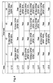
FIG.4 is a chart representing the assignment of the channels on the links of the network portion represented inFig.3 and the modulation format used in the said assigned channels. -
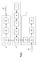
FIG.5 is a diagram of the structure of a control plane equipment, a transmitter of a source node ans a receiver of a destination node. -
FIG.6 is a diagram of spectral representation of three optical signals with different rates distributed on three adjacent channels and the application of an asymmetric digital pulse filter on the signal of the channel located in the middle; -
FIG.7 is a diagram of a variable spectral grid; - As used herein, the term "WDM" refers to the acronym Wavelength Division Multiplexing;
- As used herein, the term "Gb/s" refers to the Gigabit per second unit;
- As used herein, the term "QPSK" refers to the acronym Quadrature Phase Shift Keying;
- As used herein, the term "DPSK" refers to the acronym Differential Phase Shift Keying;
- As used herein, the term "modulation format" refers to the modulation scheme, for example Quadrature Phase Shift Keying (QPSK), the number of polarisations used (1 or 2) and the baud rate (or, equivalently, the number of symbols per second), for example 10GBauds. These parameters yield the bit rate of the modulation, for example 40Gb/s;
- As used herein, the term "adjacent channel or adjacent channels" refers to channels that are directly adjacent so that there is one (if the channel is located on a border of the spectrum) or two channels that are adjacent to a given channel (one on the left side of the spectrum and one on the right side of the spectrum)
- The embodiments of the present invention refer to a method for transmitting a signal from a source node to a destination node on a channel of a wavelength division multiplexing (WDM) network comprising a plurality of channels wherein a digital pulse shape filter is applied on the signal to reduce or reshape its spectral spreading.
-
Fig.2 represents an example of application of 4 digital pulse shape filters noted F1, F2, F3 and F4 on the signals of the 4 channels described infigure 1 to limit their spectral spreading and therefore to reduce the overlapping between adjacent channels. -
Fig.3 represents a diagram of a network portion comprising six nodes referenced Ni with i=1...6 and optical links Lj-k with j and k corresponding to the numbers i of the nodes connected by the said links. Furthermore, the network comprises 4 WDM channels noted λ1 with 1=1...4. In practice, the number of channels is obviously higher, for example 80 WDM channels. - At a given time t1, the occupancy or assignment of the channels is as described in
Fig.4 . -
Fig.4 represents a chart with the channels of the network portion presented inFig.3 as horizontal inputs and the links of the network portion presented inFig.3 as vertical inputs. The term "free" means that no signal is transmitted on the corresponding channel and the corresponding link. - For the occupied channels, the modulation format and the digital pulse shape filter (DPSF) type used for the transmission on the corresponding link are given. The type of digital pulse shape filter is herein defined by its spectral width in percentage of the channel spacing Δλ.Futhermore, it has to be noted that the digital pulse shape filters are characterized not only by their spectral width but also by the shape of their envelope so that different pulse shape filters having the same spectral width may lead to different signal quality at destination. Thus, for sake of simplicity, in the chart of
figure 3 , the digital pulse shape filters are represented only by their spectral width (DPSF). However, in practice, the shape of the envelope of the digital pulse filter, for example Hanning, Hamming, Blackman-Harris or Gaussian windows may be used for the envelope of the filter, is also taken into account in the determination of the digital pulse shape filter to be applied. - The determination of the applied digital pulse shape filter is achieved based on the modulation format and the spectral spreading of the signals transmitted on the adjacent channels and will be described in more details in the following of the description.
- It has to be noted that, in the present example, the different modulation schemes are QPSK and DPSK and the different modulation bitrates are 10, 40 or 100 Gb/s, however, any other modulation formats can be used within the scope of the embodiments of the present invention;
- Based on the situation previously described for the network portion of
figure 3 , a request is received from a client for a transmission of a given amount of data from node N1 to node N6 with a given signal quality and a given data rate. Selection means of a control plane equipment then determine the most suitable modulation format to match with the requirements of the request in terms of data rates and signal quality at destination. -
Fig.5 describes an example of structure of a control plane equipment 1, a transmitter 3 of a source node and a receiver 5 of a destination node. - The client request is received at the control plane level by reception means 7. Based on the requirements of the client request (signal quality at destination and bitrate), selection means 9 select a modulation format, in the present case, the result of the selection is a 40 Gb/s QPSK signal.
- Then, planning means 11 search for a physical path and an available channel along the said path from the source node N1 to the destination node N6 of the client request.
- The said planning means determine that the channel λ3 is available along the path N1-N2-N4-N6 through links L1-2, L2-4 and L4-6. The channel λ3 is therefore assigned or reserved for the requested transmission.
- Then, processing means 13 determine the spectral spreading of the optical signals located on the adjacent channels (λ2 and λ4) along the path N1-N2-N4-N6.
- As the processing of the client requests and the assignment of the channels are achieved at the control plane level, a control plane equipment 1 has therefore access to a mapping of the distribution of signals among the channels transmitted across the links Ljk and nodes Ni of the network. As a consequence, the said control plane equipment has access to the modulation format of the signal transmitted on a given channel across a given link and the type of the applied digital pulse shape filter if any. Based on this information, a control plane equipment 1 is therefore capable of determining the spectral spreading of the said transmitted signal.
- In the present example, on the first adjacent channel corresponding to channel λ2, there is a 10Gb/s QPSK signal with a spectral spreading of 80% of the channel spacing Δλ on the link L1-2 and a 40Gb/s QPSK signal with a spectral spreading of 100% of the channel spacing Δλ on the link L4-6 and on the second adjacent channel corresponding to channel λ4, there is a 10 Gb/s DPSK signal with a spectral spreading of 70% of the channel spacing on the links L1-2 and L2-4 and a 100 Gb/s QPSK signal with a spectral spreading of 120% of the channel spacing on the link L4-6.
- Thus, based on the modulation format (if no filter is applied) or the applied filters, processing means 13 of a control plane equipment 1 determine the spectral spreading of the signals located on the adjacent channels.
- Based on the modulation format selected by the selection means 9, the spectral spreading of the signals located on the adjacent channels determined by the processing means 13 and the channel spacing Δλ, determination means 15 determine the most suitable digital pulse shape filter to apply on the signal to be transmitted on the assigned channel, corresponding to channel λ3 in the present example.
- Different embodiments can be considered in the determination of the most suitable digital pulse shape filter.
- According to a first embodiment, determination means 15 determine the largest spectral spreading between both adjacent channels which corresponds to the spectral spreading associated with the 100 Gb/s QPSK signal and the applied digital pulse shape filter having a spectral spreading or spectral width of 120% of the channel spacing Δλ in the present example.
- Thus, knowing the largest spectral spreading (120% of Δλ) on the adjacent channels along the path and knowing the channel spacing Δλ, determination means 15 determine the available spectral width of the assigned channel, corresponding herein to 80% of Δλ, and select, among a set of predetermined digital pulse shape filters, the most suitable digital pulse shape filter according to the said available spectral width.
- The set of predetermined digital pulse shape filters corresponds for example to digital pulse shape filters stored in a database of a control plane equipment 1 and sorted as a function of the modulation format corresponding to their shape and as a function of their spectral spreading.
- For example, a digital pulse shape filter has a shape corresponding to a 40Gb/s QPSK signal and has a spectral spreading of 100% of the channel spacing Δλ.
- Indeed, as one can notice in
figure 2 , the envelope of the signals for different modulation formats are different so that the shape of the applied filter has to be adapted to the said envelope. Moreover, for a given modulation format and a given spectral width, different envelope shapes of filter (Hamming, Hanning, Gaussian, Blackman-Harris...) may be applied and lead to different signal quality at destination. - Furthermore, by most suitable, it is meant herein that the digital pulse shape filter provides the best quality signal ( i.e. the minimal bit error rate) at destination taking into account the interference situation. As a consequence, such a criterion is reached by choosing the digital pulse shape filter adapted to the selected modulation format and having the spectral spreading the closest to the available spectral width of the assigned channel and being smaller than the said available spectral width to avoid overlapping with adjacent channels. However, other settings, allowing for example partial overlapping of adjacent signals, may also be applied in the digital pulse shape filter selection depending on the required quality of signal at destination.
- In the present case, the pulse shape filter applied to the signal transmitted on channel λ3 is therefore a pulse shape filter adapted to a 40Gb/s QPSK signal and having a spectral spreading of 80% of the channel spacing Δλ. For the envelope shape selection, the envelope shape leading to the smallest bit error rate (BER) at destination is selected based on preliminary measurements stored, for example, in a look-up table. For example, in the present case, for a 40Gb/s QPSK signal having a spectral spreading of 80% of the channel spacing Δλ, the look-up table may indicate that a Hamming envelope shape corresponds to the envelope shape producing the smallest BER at destination. The applied digital pulse shape filter has therefore a Hamming envelope shape. In practice, an optimal digital pulse filter is selected from a collection of digital pulse filters stored in a look-up table or database, a spectral width situation being associated with a digital pulse filter providing the best signal quality at destination, said signal quality being determined based on measurements achieved previously.
- Moreover, in the specific case where all the adjacent channels are "free" which means that no signals are transmitted on the adjacent channels along the path of the transmission, a digital pulse shape filter having a predetermined spectral spreading is chosen, for example, the said predetermined spectral spreading can be 70% of the channel spacing Δλ for a 10 Gb/s DPSK signal, 90% of the channel spacing Δλ, for a 40 Gb/s QPSK signal and 110% of the channel spacing Δλ for a 100 Gb/s QPSK signal. Besides, a spectral spreading limit can be defined for the channels at a border of the spectral grid.
- According to a second embodiment, the set of predetermined digital pulse shape filters comprises asymmetric digital pulse shape filters.
-
Figure 6 represents an example of asymmetric digital pulse shape filter applied on a signal located on channel λ2 and having a smallest spectral spreading on the first side corresponding to the side toward channel λ1 than on the second side corresponding to the side toward λ3. Indeed, if the spectral spreading of the signals located on channel λ3 are smaller than the spectral spreading of the signals transmitted on λ1 along the path, the application of an asymmetric digital pulse filter allows to improve the signal quality at destination as a largest part of the signal is transmitted without increasing the overlapping with the adjacent channels. - With the previous example described in
figures 3 and4 , the determination of the largest spectral spreading along the path by the determination means 15 is achieved separately on each adjacent channel, λ2 and λ4 in the present case. - It is thus determined that the largest spectral spreading on channel λ2 is a 40 Gb/s QPSK signal with a spectral spreading of 100% of the channel spacing Δλ on the link L4-6 and the largest spectral spreading on channel λ4 is a 100 Gb/s QPSK signal with a spectral spreading of 120% of the channel spacing Δλ on the link L4-6.
- Thus, knowing the largest spectral spreadings (100% of Δλ on λ2 and 120% of Δλ on λ4) on the first and the second adjacent channels along the path and knowing the channel spacing Δλ, determination means 15 determine the available spectral width of the assigned channel, corresponding herein to 100% of Δλ on the first side corresponding to the first channel and 80% of Δλ on the second side corresponding to the second channel. The selection, among a set of predetermined digital pulse shape filters, of the most suitable digital pulse shape filter is then achieved according to the said available spectral widths.
- As previously, the most suitable digital pulse filter corresponds to a digital pulse shape filter adapted to the modulation format of the signal and having the closest spectral spreading with respect to the available spectral widths. In the present case, such selection leads to a digital pulse shape filter with a shape corresponding to a 40Gb/s QPSK signal and with a spectral spreading of 100% of Δλ on the first side and a spectral spreading of 80% of the channel spacing Δλ, on the second side. As in the first embodiment described previously, the shape of the envelope is also determined based on a stored look-up table to select the digital pulse filter producing the smallest BER at destination.
- When the most suitable digital pulse shape filter is determined by the determination means 15 of a control plane equipment 1, an indication of the said determined digital pulse shape filter, for example an index of a digital pulse shape filter, is sent to control means 17 of the source node associated with a transmitter 3 of the said source node as well as the control means 19 of the destination node associated with a receiver 5 of the said destination node. Indeed, the different pulse shape digital filters and their associated index are stored in a look-up table in the control means 17, 19 of the transmitter 3 and the receiver 5 so that when the control means 17, 19 receive an information of an index, they are capable of retrieving the digital pulse shape filter associated with the received index.
- On the transmitter 3 side, digital to analogical conversion means 21 are configured according to the control means 17 instructions to applied the determined digital pulse shape filter on the signal used for the modulation of an optical carrier by modulation means 23, the modulated signal being then transmitted toward a destination node through optical transmission means 25.
- On the receiver 5 side, the signal transmitted through the optical transmission means 25 is received by filtering means 27 configured by the control means 19 according to the digital pulse shape filter applied by the transmitter 3 of the source node. The filtered signal is sent to analogical to digital conversion means 29 and then to digital signal processing means 31 where data transmitted by the signal are retrieved.
- Furthermore, the embodiments of the present invention can also be applied in a network using a variable spectral grid, that is to say, a spectral grid, as described in
figure 7 , with different channel spacings Δλ1, Δλ2, Δλ3, Δλ4 between the adjacent channels. However, it is not referred to a spectral grid wherein channel spacing varies dynamically. A channel spacing can therefore be different than the channel spacing of an adjacent channel but the channel spacings are fixed over time. - Thus, with a variable spectral grid, the determination of the most suitable digital pulse shape filter takes into account the particular channel spacing λΔ1 of the assigned channel λ1.
- Moreover, as described previously, the use of digital pulse filter allows to reduce the spectral spreading of the signal. Thus, the value of the channel spacings, in the case of a variable spectral grid, can be defined according to the spectral spreading of a digital pulse shape filter providing the desired quality of signal at destination. For example, if it is determined that a digital pulse shape filter having a spectral spreading of 25 GHz on a 40 Gb/s QPSK signal provides the desired quality of signal at destination, the channel spacing aimed at receiving 40 Gb/s QPSK signals can be defined to be 25 GHz.
- Thus, the embodiments of the present invention by using digital pulse shape filters for the transmission from source to destination of signals and by selecting the most suitable filter to apply to the transmitted signal according to the largest spectral spreading of the signals transmitted on the adjacent channels along the path allow to limit the spectral occupancy of the channels leading to an improved trade-off between the quality of signal and the amount of data transmitted.
Claims (10)
- Method for transmitting a signal along a path from a source node to a destination node on a channel in a wavelength division multiplexing network comprising a plurality of channels wherein the said method comprises the following steps:- receiving a request for transmitting a signal from a source node to a destination node,- selecting a path and a channel (λ), along the said path, which is available for a transmission of the signal,- selecting a modulation format for the transmission of the signal according to the received request,- determining the spectral spreading of the at least one signal transmitted on the at least one channel (λ) adjacent to the selected channel (λ) along the said path according to the modulation format of the said at least one signal,- determining a digital pulse shape filter to apply to the signal to be transmitted on the selected channel according to the selected modulation format and the determined spectral spreading of the at least one signal transmitted on the at least one adjacent channel.
- Method in accordance with claim 1 wherein the step of determination of a digital pulse shape filter comprises:- determining the largest spectral spreading among the determined spectral spreadings,- determining the available spectral width for the signal to be transmitted on the selected channel according to the largest determined spectral spreading,- determining, among a set of predetermined digital pulse filters, a digital pulse shape filter adapted to the selected modulation format and having a spectral width being the closest to the determined available spectral width and smaller than the said determined available spectral width.
- Method in accordance with claim 1 wherein the step of determination of a digital pulse shape filter comprises:- determining the largest spectral spreading among the determined spectral spreadings on one hand on a first adjacent channel (λ) and on the other hand on a second adjacent channel (λ),- determining a first side available spectral width according to the largest spectral spreading determined on the first adjacent channel (λ) and a second side available spectral width according to largest spectral spreading determined on the second adjacent channel (λ),- determining, among a set of predetermined digital pulse filters comprising asymmetrical filters, a digital pulse shape filter adapted to the selected modulation format and having a spectral width being on one side, corresponding to the first side, the closest to the determined first side available spectral width and smaller than the said first side determined available spectral width and on the other side corresponding to the second side the closest to the determined second side available spectral width and smaller than the said second side determined available spectral width.
- Method in accordance with one of the previous claims wherein the wavelength division multiplexing channels are distributed on a spectral grid having a constant spectral spacing (Δλ).
- Method in accordance with one of the claims 1 to 3 wherein the wavelength division multiplexing channels are distributed on a spectral grid having a variable spectral spacing (Δλ).
- Control plane equipment (1) of a wavelength division multiplexing network comprising a plurality of channels (λ) comprising:- reception means (7) adapted for receiving a request of transmission of a signal from a source node to a destination node,- selection means (9) adapted for selecting a modulation format for the transmission of the signal according to the received request,- planning means (11) adapted for determining a path and for assigning a channel (λ) along the said path according to the received transmission request;- processing means (13) adapted for determining spectral spreading of signals transmitted on the channels (λ) according to the modulation format of the said signals,- determination means (15) adapted for determining a digital pulse shape filter to apply to the signal to be transmitted on the assigned channel (λ) according to the selected modulation format and the determined spectral spreading of the at least one signal transmitted on the at least one channel(λ) adjacent to the assigned channel.
- Transmitter (3) of a wavelength division multiplexing network comprising a plurality of channels (λ) comprising:- control means (17) adapted to receive, from a control plane equipment (1), an indication of a digital pulse shape filter to apply to a signal and to configure digital to analogical conversion means (21) to apply the said digital pulse filter;- digital to analogical conversion means (21) comprising means to apply a digital pulse filter;
- Transmitter (3) in accordance with claim 7 comprising also modulation means (23), the said modulation means (23) comprising:- processing means adapted for modulating an optical carrier according to the filtered signal provided by the digital to analogical means (21);
- Receiver (5) of a wavelength division multiplexing network comprising a plurality of channels (λ) comprising:- reception means adapted to receive a signal transmitted on a channel through optical transmission means (25),- control means (19) adapted to receive, from a control plane equipment (1), an indication of a digital pulse shape filter applied to the transmitted signal, to determine a filtering function to apply to the transmitted signal according to the applied digital pulse shape filter and to transmit the said determined filtering function to filtering means (27);- filtering means (27) adapted to receive and apply a determined filtering function on a signal.
- Receiver (5) in accordance with claim 9 comprising also:- analogical to digital conversion means (29) adapted to convert a filtered analogical signal into a numerical signal,- digital signal processing means (31) adapted to receive and process a numerical signal transmitted by the analogical to digital conversion means (29).
Priority Applications (1)
| Application Number | Priority Date | Filing Date | Title |
|---|---|---|---|
| EP11290389.3A EP2566082B1 (en) | 2011-09-02 | 2011-09-02 | Method for transmitting a signal in a wavelength division multiplexing optical network |
Applications Claiming Priority (1)
| Application Number | Priority Date | Filing Date | Title |
|---|---|---|---|
| EP11290389.3A EP2566082B1 (en) | 2011-09-02 | 2011-09-02 | Method for transmitting a signal in a wavelength division multiplexing optical network |
Publications (2)
| Publication Number | Publication Date |
|---|---|
| EP2566082A1 true EP2566082A1 (en) | 2013-03-06 |
| EP2566082B1 EP2566082B1 (en) | 2018-02-14 |
Family
ID=44719756
Family Applications (1)
| Application Number | Title | Priority Date | Filing Date |
|---|---|---|---|
| EP11290389.3A Not-in-force EP2566082B1 (en) | 2011-09-02 | 2011-09-02 | Method for transmitting a signal in a wavelength division multiplexing optical network |
Country Status (1)
| Country | Link |
|---|---|
| EP (1) | EP2566082B1 (en) |
Cited By (2)
| Publication number | Priority date | Publication date | Assignee | Title |
|---|---|---|---|---|
| US9635760B1 (en) | 2016-01-19 | 2017-04-25 | Alcatel-Lucent Usa Inc. | 0204 shifted vias with merge pads |
| WO2017079184A1 (en) * | 2015-11-02 | 2017-05-11 | Alcatel-Lucent Usa Inc. | Optical modem |
Citations (2)
| Publication number | Priority date | Publication date | Assignee | Title |
|---|---|---|---|---|
| US20040146297A1 (en) * | 2003-01-27 | 2004-07-29 | Lucent Technologies Inc. | Method and system for increasing the capacity and spectral effeciency of optical transmission |
| US20110176815A1 (en) * | 2010-01-21 | 2011-07-21 | Frankel Michael Y | Multi-channel optical transceiver with offset quadrature amplitude modulation |
-
2011
- 2011-09-02 EP EP11290389.3A patent/EP2566082B1/en not_active Not-in-force
Patent Citations (2)
| Publication number | Priority date | Publication date | Assignee | Title |
|---|---|---|---|---|
| US20040146297A1 (en) * | 2003-01-27 | 2004-07-29 | Lucent Technologies Inc. | Method and system for increasing the capacity and spectral effeciency of optical transmission |
| US20110176815A1 (en) * | 2010-01-21 | 2011-07-21 | Frankel Michael Y | Multi-channel optical transceiver with offset quadrature amplitude modulation |
Non-Patent Citations (3)
| Title |
|---|
| CHRISTODOULOPOULOS K ET AL: "Elastic Bandwidth Allocation in Flexible OFDM-Based Optical Networks", JOURNAL OF LIGHTWAVE TECHNOLOGY, IEEE SERVICE CENTER, NEW YORK, NY, US, vol. 29, no. 9, 1 May 2011 (2011-05-01), pages 1354 - 1366, XP011353989, ISSN: 0733-8724, DOI: 10.1109/JLT.2011.2125777 * |
| MASAHIKO JINNO ET AL: "Distance-adaptive spectrum resource allocation in spectrum-sliced elastic optical path network [Topics in Optical Communications]", IEEE COMMUNICATIONS MAGAZINE, IEEE SERVICE CENTER, PISCATAWAY, US, vol. 48, no. 8, 1 August 2010 (2010-08-01), pages 138 - 145, XP011316007, ISSN: 0163-6804 * |
| MASAHIKO JINNO ET AL: "Spectrum-efficient and scalable elastic optical path network: architecture, benefits, and enabling technologies", IEEE COMMUNICATIONS MAGAZINE, IEEE SERVICE CENTER, PISCATAWAY, US, vol. 47, no. 11, 1 November 2009 (2009-11-01), pages 66 - 73, XP011279184, ISSN: 0163-6804, DOI: 10.1109/MCOM.2009.5307468 * |
Cited By (2)
| Publication number | Priority date | Publication date | Assignee | Title |
|---|---|---|---|---|
| WO2017079184A1 (en) * | 2015-11-02 | 2017-05-11 | Alcatel-Lucent Usa Inc. | Optical modem |
| US9635760B1 (en) | 2016-01-19 | 2017-04-25 | Alcatel-Lucent Usa Inc. | 0204 shifted vias with merge pads |
Also Published As
| Publication number | Publication date |
|---|---|
| EP2566082B1 (en) | 2018-02-14 |
Similar Documents
| Publication | Publication Date | Title |
|---|---|---|
| US9831947B2 (en) | Margin determination systems and methods in optical networks | |
| US9531477B2 (en) | Method and apparatus for transmitting and receiving client signal in optical transport network | |
| US20130045006A1 (en) | Method and a network node for improving bandwidth efficiency in an optical network | |
| JP5940684B2 (en) | Change spectral position of optical path | |
| EP3579460B1 (en) | Path selection in optical network for optical nodes with flexible baud rate and modulation format | |
| EP2797248A2 (en) | Crosstalk reduction in optical networks using variable subcarrier spectral allocation | |
| US10461881B2 (en) | Method and system for assigning modulation format in optical networks | |
| US9806804B2 (en) | Method and apparatus for configuring an optical path | |
| WO2011030897A1 (en) | Band-variable communication method, band-variable communication apparatus, transmission band deciding apparatus, transmission band deciding method, node apparatus, communication path setting system, and communication path setting method | |
| CN111698581B (en) | Apparatus and method for controlling upstream transmission of bursts in a passive optical network | |
| JP7800528B2 (en) | Optical node device and optical bandwidth allocation method | |
| US9768904B2 (en) | Method and apparatus for allocating slots for transmission of data | |
| EP2983316B1 (en) | Method and apparatus for multicarrier spectrum transition in service hitless mode | |
| JP6289500B2 (en) | Adaptive data transmission format for optical transmission networks. | |
| EP2566082A1 (en) | Method for transmitting a signal in a wavelength division multiplexing optical network | |
| Klinkowski et al. | A heuristic algorithm for routing, spectrum, transceiver and regeneration allocation problem in elastic optical networks | |
| EP3560122A1 (en) | Subcarrier diversity in optical communication systems | |
| KR101607473B1 (en) | Method of allocating bandwidth in an optical network | |
| Garrido et al. | Routing, code, modulation level and spectrum assignment (RCMLSA) algorithm for elastic optical networks | |
| EP3104537A1 (en) | Method for improving signal transmission quality in an optical network and associated equipment | |
| EP2782267B1 (en) | Optical signal transmission method, apparatus and system | |
| EP3382912B1 (en) | Digital modulation method, transmission method and associated equipment | |
| Colombo et al. | Reconfigurable DP-16QAM/QPSK transponders for the transmission of coherent 200G carriers in a flexgrid super-channel arrangement | |
| Colombo | Reconfigurable DP-16QAM/QPSK transponders for the transmission of coherent 200 Gb/s carriers in a flexgrid super-channel arrangement | |
| Xia et al. | High speed and flexible optical transport network |
Legal Events
| Date | Code | Title | Description |
|---|---|---|---|
| PUAI | Public reference made under article 153(3) epc to a published international application that has entered the european phase |
Free format text: ORIGINAL CODE: 0009012 |
|
| 17P | Request for examination filed |
Effective date: 20120627 |
|
| AK | Designated contracting states |
Kind code of ref document: A1 Designated state(s): AL AT BE BG CH CY CZ DE DK EE ES FI FR GB GR HR HU IE IS IT LI LT LU LV MC MK MT NL NO PL PT RO RS SE SI SK SM TR |
|
| AX | Request for extension of the european patent |
Extension state: BA ME |
|
| 111Z | Information provided on other rights and legal means of execution |
Free format text: AL AT BE BG CH CY CZ DE DK EE ES FI FR GB GR HR HU IE IS IT LI LT LU LV MC MK MT NL NO PL PT RO RS SE SI SK SM TR Effective date: 20130410 |
|
| RAP1 | Party data changed (applicant data changed or rights of an application transferred) |
Owner name: ALCATEL LUCENT |
|
| D11X | Information provided on other rights and legal means of execution (deleted) | ||
| GRAP | Despatch of communication of intention to grant a patent |
Free format text: ORIGINAL CODE: EPIDOSNIGR1 |
|
| RIC1 | Information provided on ipc code assigned before grant |
Ipc: H04B 10/69 20130101ALI20170714BHEP Ipc: H04B 10/516 20130101ALI20170714BHEP Ipc: H04J 14/02 20060101AFI20170714BHEP |
|
| INTG | Intention to grant announced |
Effective date: 20170818 |
|
| GRAS | Grant fee paid |
Free format text: ORIGINAL CODE: EPIDOSNIGR3 |
|
| GRAA | (expected) grant |
Free format text: ORIGINAL CODE: 0009210 |
|
| AK | Designated contracting states |
Kind code of ref document: B1 Designated state(s): AL AT BE BG CH CY CZ DE DK EE ES FI FR GB GR HR HU IE IS IT LI LT LU LV MC MK MT NL NO PL PT RO RS SE SI SK SM TR |
|
| REG | Reference to a national code |
Ref country code: GB Ref legal event code: FG4D |
|
| REG | Reference to a national code |
Ref country code: CH Ref legal event code: EP |
|
| REG | Reference to a national code |
Ref country code: IE Ref legal event code: FG4D |
|
| REG | Reference to a national code |
Ref country code: DE Ref legal event code: R096 Ref document number: 602011045606 Country of ref document: DE Ref country code: AT Ref legal event code: REF Ref document number: 970511 Country of ref document: AT Kind code of ref document: T Effective date: 20180315 |
|
| REG | Reference to a national code |
Ref country code: CH Ref legal event code: PCOW Free format text: NEW ADDRESS: SITE NOKIA PARIS SACLAY ROUTE DE VILLEJUST, 91620 NOZAY (FR) |
|
| RAP2 | Party data changed (patent owner data changed or rights of a patent transferred) |
Owner name: ALCATEL LUCENT |
|
| REG | Reference to a national code |
Ref country code: NL Ref legal event code: MP Effective date: 20180214 |
|
| REG | Reference to a national code |
Ref country code: AT Ref legal event code: MK05 Ref document number: 970511 Country of ref document: AT Kind code of ref document: T Effective date: 20180214 |
|
| PG25 | Lapsed in a contracting state [announced via postgrant information from national office to epo] |
Ref country code: NL Free format text: LAPSE BECAUSE OF FAILURE TO SUBMIT A TRANSLATION OF THE DESCRIPTION OR TO PAY THE FEE WITHIN THE PRESCRIBED TIME-LIMIT Effective date: 20180214 Ref country code: ES Free format text: LAPSE BECAUSE OF FAILURE TO SUBMIT A TRANSLATION OF THE DESCRIPTION OR TO PAY THE FEE WITHIN THE PRESCRIBED TIME-LIMIT Effective date: 20180214 Ref country code: HR Free format text: LAPSE BECAUSE OF FAILURE TO SUBMIT A TRANSLATION OF THE DESCRIPTION OR TO PAY THE FEE WITHIN THE PRESCRIBED TIME-LIMIT Effective date: 20180214 Ref country code: NO Free format text: LAPSE BECAUSE OF FAILURE TO SUBMIT A TRANSLATION OF THE DESCRIPTION OR TO PAY THE FEE WITHIN THE PRESCRIBED TIME-LIMIT Effective date: 20180514 Ref country code: FI Free format text: LAPSE BECAUSE OF FAILURE TO SUBMIT A TRANSLATION OF THE DESCRIPTION OR TO PAY THE FEE WITHIN THE PRESCRIBED TIME-LIMIT Effective date: 20180214 Ref country code: LT Free format text: LAPSE BECAUSE OF FAILURE TO SUBMIT A TRANSLATION OF THE DESCRIPTION OR TO PAY THE FEE WITHIN THE PRESCRIBED TIME-LIMIT Effective date: 20180214 Ref country code: CY Free format text: LAPSE BECAUSE OF FAILURE TO SUBMIT A TRANSLATION OF THE DESCRIPTION OR TO PAY THE FEE WITHIN THE PRESCRIBED TIME-LIMIT Effective date: 20180214 |
|
| PG25 | Lapsed in a contracting state [announced via postgrant information from national office to epo] |
Ref country code: RS Free format text: LAPSE BECAUSE OF FAILURE TO SUBMIT A TRANSLATION OF THE DESCRIPTION OR TO PAY THE FEE WITHIN THE PRESCRIBED TIME-LIMIT Effective date: 20180214 Ref country code: LV Free format text: LAPSE BECAUSE OF FAILURE TO SUBMIT A TRANSLATION OF THE DESCRIPTION OR TO PAY THE FEE WITHIN THE PRESCRIBED TIME-LIMIT Effective date: 20180214 Ref country code: SE Free format text: LAPSE BECAUSE OF FAILURE TO SUBMIT A TRANSLATION OF THE DESCRIPTION OR TO PAY THE FEE WITHIN THE PRESCRIBED TIME-LIMIT Effective date: 20180214 Ref country code: BG Free format text: LAPSE BECAUSE OF FAILURE TO SUBMIT A TRANSLATION OF THE DESCRIPTION OR TO PAY THE FEE WITHIN THE PRESCRIBED TIME-LIMIT Effective date: 20180514 Ref country code: GR Free format text: LAPSE BECAUSE OF FAILURE TO SUBMIT A TRANSLATION OF THE DESCRIPTION OR TO PAY THE FEE WITHIN THE PRESCRIBED TIME-LIMIT Effective date: 20180515 Ref country code: AT Free format text: LAPSE BECAUSE OF FAILURE TO SUBMIT A TRANSLATION OF THE DESCRIPTION OR TO PAY THE FEE WITHIN THE PRESCRIBED TIME-LIMIT Effective date: 20180214 |
|
| REG | Reference to a national code |
Ref country code: FR Ref legal event code: PLFP Year of fee payment: 8 |
|
| PG25 | Lapsed in a contracting state [announced via postgrant information from national office to epo] |
Ref country code: AL Free format text: LAPSE BECAUSE OF FAILURE TO SUBMIT A TRANSLATION OF THE DESCRIPTION OR TO PAY THE FEE WITHIN THE PRESCRIBED TIME-LIMIT Effective date: 20180214 Ref country code: RO Free format text: LAPSE BECAUSE OF FAILURE TO SUBMIT A TRANSLATION OF THE DESCRIPTION OR TO PAY THE FEE WITHIN THE PRESCRIBED TIME-LIMIT Effective date: 20180214 Ref country code: IT Free format text: LAPSE BECAUSE OF FAILURE TO SUBMIT A TRANSLATION OF THE DESCRIPTION OR TO PAY THE FEE WITHIN THE PRESCRIBED TIME-LIMIT Effective date: 20180214 Ref country code: PL Free format text: LAPSE BECAUSE OF FAILURE TO SUBMIT A TRANSLATION OF THE DESCRIPTION OR TO PAY THE FEE WITHIN THE PRESCRIBED TIME-LIMIT Effective date: 20180214 Ref country code: EE Free format text: LAPSE BECAUSE OF FAILURE TO SUBMIT A TRANSLATION OF THE DESCRIPTION OR TO PAY THE FEE WITHIN THE PRESCRIBED TIME-LIMIT Effective date: 20180214 |
|
| REG | Reference to a national code |
Ref country code: DE Ref legal event code: R097 Ref document number: 602011045606 Country of ref document: DE |
|
| PG25 | Lapsed in a contracting state [announced via postgrant information from national office to epo] |
Ref country code: SM Free format text: LAPSE BECAUSE OF FAILURE TO SUBMIT A TRANSLATION OF THE DESCRIPTION OR TO PAY THE FEE WITHIN THE PRESCRIBED TIME-LIMIT Effective date: 20180214 Ref country code: SK Free format text: LAPSE BECAUSE OF FAILURE TO SUBMIT A TRANSLATION OF THE DESCRIPTION OR TO PAY THE FEE WITHIN THE PRESCRIBED TIME-LIMIT Effective date: 20180214 Ref country code: CZ Free format text: LAPSE BECAUSE OF FAILURE TO SUBMIT A TRANSLATION OF THE DESCRIPTION OR TO PAY THE FEE WITHIN THE PRESCRIBED TIME-LIMIT Effective date: 20180214 Ref country code: DK Free format text: LAPSE BECAUSE OF FAILURE TO SUBMIT A TRANSLATION OF THE DESCRIPTION OR TO PAY THE FEE WITHIN THE PRESCRIBED TIME-LIMIT Effective date: 20180214 |
|
| PLBE | No opposition filed within time limit |
Free format text: ORIGINAL CODE: 0009261 |
|
| STAA | Information on the status of an ep patent application or granted ep patent |
Free format text: STATUS: NO OPPOSITION FILED WITHIN TIME LIMIT |
|
| 26N | No opposition filed |
Effective date: 20181115 |
|
| PG25 | Lapsed in a contracting state [announced via postgrant information from national office to epo] |
Ref country code: SI Free format text: LAPSE BECAUSE OF FAILURE TO SUBMIT A TRANSLATION OF THE DESCRIPTION OR TO PAY THE FEE WITHIN THE PRESCRIBED TIME-LIMIT Effective date: 20180214 |
|
| PG25 | Lapsed in a contracting state [announced via postgrant information from national office to epo] |
Ref country code: MC Free format text: LAPSE BECAUSE OF FAILURE TO SUBMIT A TRANSLATION OF THE DESCRIPTION OR TO PAY THE FEE WITHIN THE PRESCRIBED TIME-LIMIT Effective date: 20180214 |
|
| REG | Reference to a national code |
Ref country code: CH Ref legal event code: PL |
|
| REG | Reference to a national code |
Ref country code: BE Ref legal event code: MM Effective date: 20180930 |
|
| REG | Reference to a national code |
Ref country code: IE Ref legal event code: MM4A |
|
| PG25 | Lapsed in a contracting state [announced via postgrant information from national office to epo] |
Ref country code: LU Free format text: LAPSE BECAUSE OF NON-PAYMENT OF DUE FEES Effective date: 20180902 |
|
| PG25 | Lapsed in a contracting state [announced via postgrant information from national office to epo] |
Ref country code: IE Free format text: LAPSE BECAUSE OF NON-PAYMENT OF DUE FEES Effective date: 20180902 |
|
| PG25 | Lapsed in a contracting state [announced via postgrant information from national office to epo] |
Ref country code: LI Free format text: LAPSE BECAUSE OF NON-PAYMENT OF DUE FEES Effective date: 20180930 Ref country code: CH Free format text: LAPSE BECAUSE OF NON-PAYMENT OF DUE FEES Effective date: 20180930 Ref country code: BE Free format text: LAPSE BECAUSE OF NON-PAYMENT OF DUE FEES Effective date: 20180930 |
|
| PGFP | Annual fee paid to national office [announced via postgrant information from national office to epo] |
Ref country code: DE Payment date: 20190820 Year of fee payment: 9 Ref country code: FR Payment date: 20190815 Year of fee payment: 9 |
|
| PGFP | Annual fee paid to national office [announced via postgrant information from national office to epo] |
Ref country code: GB Payment date: 20190830 Year of fee payment: 9 |
|
| PG25 | Lapsed in a contracting state [announced via postgrant information from national office to epo] |
Ref country code: MT Free format text: LAPSE BECAUSE OF NON-PAYMENT OF DUE FEES Effective date: 20180902 |
|
| PG25 | Lapsed in a contracting state [announced via postgrant information from national office to epo] |
Ref country code: TR Free format text: LAPSE BECAUSE OF FAILURE TO SUBMIT A TRANSLATION OF THE DESCRIPTION OR TO PAY THE FEE WITHIN THE PRESCRIBED TIME-LIMIT Effective date: 20180214 |
|
| PG25 | Lapsed in a contracting state [announced via postgrant information from national office to epo] |
Ref country code: HU Free format text: LAPSE BECAUSE OF FAILURE TO SUBMIT A TRANSLATION OF THE DESCRIPTION OR TO PAY THE FEE WITHIN THE PRESCRIBED TIME-LIMIT; INVALID AB INITIO Effective date: 20110902 Ref country code: PT Free format text: LAPSE BECAUSE OF FAILURE TO SUBMIT A TRANSLATION OF THE DESCRIPTION OR TO PAY THE FEE WITHIN THE PRESCRIBED TIME-LIMIT Effective date: 20180214 |
|
| PG25 | Lapsed in a contracting state [announced via postgrant information from national office to epo] |
Ref country code: MK Free format text: LAPSE BECAUSE OF NON-PAYMENT OF DUE FEES Effective date: 20180214 |
|
| PG25 | Lapsed in a contracting state [announced via postgrant information from national office to epo] |
Ref country code: IS Free format text: LAPSE BECAUSE OF FAILURE TO SUBMIT A TRANSLATION OF THE DESCRIPTION OR TO PAY THE FEE WITHIN THE PRESCRIBED TIME-LIMIT Effective date: 20180614 |
|
| REG | Reference to a national code |
Ref country code: DE Ref legal event code: R119 Ref document number: 602011045606 Country of ref document: DE |
|
| GBPC | Gb: european patent ceased through non-payment of renewal fee |
Effective date: 20200902 |
|
| PG25 | Lapsed in a contracting state [announced via postgrant information from national office to epo] |
Ref country code: FR Free format text: LAPSE BECAUSE OF NON-PAYMENT OF DUE FEES Effective date: 20200930 Ref country code: DE Free format text: LAPSE BECAUSE OF NON-PAYMENT OF DUE FEES Effective date: 20210401 |
|
| PG25 | Lapsed in a contracting state [announced via postgrant information from national office to epo] |
Ref country code: GB Free format text: LAPSE BECAUSE OF NON-PAYMENT OF DUE FEES Effective date: 20200902 |