EP2565819A1 - Method and apparatus for providing customer side imaging as well as bar code scanning imaging - Google Patents
Method and apparatus for providing customer side imaging as well as bar code scanning imaging Download PDFInfo
- Publication number
- EP2565819A1 EP2565819A1 EP12175085A EP12175085A EP2565819A1 EP 2565819 A1 EP2565819 A1 EP 2565819A1 EP 12175085 A EP12175085 A EP 12175085A EP 12175085 A EP12175085 A EP 12175085A EP 2565819 A1 EP2565819 A1 EP 2565819A1
- Authority
- EP
- European Patent Office
- Prior art keywords
- bar code
- scanner
- view
- customer
- field
- Prior art date
- Legal status (The legal status is an assumption and is not a legal conclusion. Google has not performed a legal analysis and makes no representation as to the accuracy of the status listed.)
- Granted
Links
Images



Classifications
-
- G—PHYSICS
- G07—CHECKING-DEVICES
- G07G—REGISTERING THE RECEIPT OF CASH, VALUABLES, OR TOKENS
- G07G1/00—Cash registers
- G07G1/0036—Checkout procedures
- G07G1/0045—Checkout procedures with a code reader for reading of an identifying code of the article to be registered, e.g. barcode reader or radio-frequency identity [RFID] reader
-
- G—PHYSICS
- G06—COMPUTING OR CALCULATING; COUNTING
- G06K—GRAPHICAL DATA READING; PRESENTATION OF DATA; RECORD CARRIERS; HANDLING RECORD CARRIERS
- G06K7/00—Methods or arrangements for sensing record carriers, e.g. for reading patterns
- G06K7/10—Methods or arrangements for sensing record carriers, e.g. for reading patterns by electromagnetic radiation, e.g. optical sensing; by corpuscular radiation
- G06K7/10544—Methods or arrangements for sensing record carriers, e.g. for reading patterns by electromagnetic radiation, e.g. optical sensing; by corpuscular radiation by scanning of the records by radiation in the optical part of the electromagnetic spectrum
- G06K7/10554—Moving beam scanning
- G06K7/10594—Beam path
- G06K7/10603—Basic scanning using moving elements
- G06K7/10613—Basic scanning using moving elements by rotation, e.g. polygon
-
- G—PHYSICS
- G06—COMPUTING OR CALCULATING; COUNTING
- G06K—GRAPHICAL DATA READING; PRESENTATION OF DATA; RECORD CARRIERS; HANDLING RECORD CARRIERS
- G06K7/00—Methods or arrangements for sensing record carriers, e.g. for reading patterns
- G06K7/10—Methods or arrangements for sensing record carriers, e.g. for reading patterns by electromagnetic radiation, e.g. optical sensing; by corpuscular radiation
- G06K7/10544—Methods or arrangements for sensing record carriers, e.g. for reading patterns by electromagnetic radiation, e.g. optical sensing; by corpuscular radiation by scanning of the records by radiation in the optical part of the electromagnetic spectrum
- G06K7/10712—Fixed beam scanning
- G06K7/10722—Photodetector array or CCD scanning
-
- G—PHYSICS
- G06—COMPUTING OR CALCULATING; COUNTING
- G06K—GRAPHICAL DATA READING; PRESENTATION OF DATA; RECORD CARRIERS; HANDLING RECORD CARRIERS
- G06K7/00—Methods or arrangements for sensing record carriers, e.g. for reading patterns
- G06K7/10—Methods or arrangements for sensing record carriers, e.g. for reading patterns by electromagnetic radiation, e.g. optical sensing; by corpuscular radiation
- G06K7/10544—Methods or arrangements for sensing record carriers, e.g. for reading patterns by electromagnetic radiation, e.g. optical sensing; by corpuscular radiation by scanning of the records by radiation in the optical part of the electromagnetic spectrum
- G06K7/10821—Methods or arrangements for sensing record carriers, e.g. for reading patterns by electromagnetic radiation, e.g. optical sensing; by corpuscular radiation by scanning of the records by radiation in the optical part of the electromagnetic spectrum further details of bar or optical code scanning devices
- G06K7/1096—Methods or arrangements for sensing record carriers, e.g. for reading patterns by electromagnetic radiation, e.g. optical sensing; by corpuscular radiation by scanning of the records by radiation in the optical part of the electromagnetic spectrum further details of bar or optical code scanning devices the scanner having more than one scanning window, e.g. two substantially orthogonally placed scanning windows for integration into a check-out counter of a super-market
-
- G—PHYSICS
- G07—CHECKING-DEVICES
- G07G—REGISTERING THE RECEIPT OF CASH, VALUABLES, OR TOKENS
- G07G1/00—Cash registers
- G07G1/0018—Constructional details, e.g. of drawer, printing means, input means
Definitions
- the present invention relates generally to improvements in bar code scanning, and more particularly to improved methods and apparatus for providing both cashier and customer side imaging.
- Image based bar code scanning is a known technique. See, for example, U.S. Patent Application Serial No. 12/342,792, filed December 23, 2008 , published as U.S. Patent Application Publication No. 2010/0155484 .
- Such approaches provide valuable techniques for obtaining images of bar codes on items at checkout at grocery, retail stores and the like.
- the imager employed typically obtains images from the cashier side of a checkout stand and not from the customer side. Thus, if a customer has a bar coded loyalty card, the customer hands the card to the store checkout person or cashier who scans it and then returns it to the customer.
- Another and different aspect of checkout is that shoppers often place large or bulky items, such as a large bag of dog food, kitty litter, potatoes, a twelve pack of carbonated drinks cans or the like on the bottom rack of the traditional shopping cart which is designed to support such items.
- large or bulky items such as a large bag of dog food, kitty litter, potatoes, a twelve pack of carbonated drinks cans or the like
- the bottom of the cart items can be missed, or alternatively may require a time consuming process to be scanned.
- the large bulky items must be boosted to the checkout surface and scanned.
- the service person may need to come around the customer side and scan the item or items with a handheld scanner.
- the present invention recognizes that situations like those described above can be handled more efficiently without adding a significant amount of new imaging hardware by adapting existing bar code imaging optics to also perform a customer side imaging function or functions.
- an image based bar code scanner having a cashier side and a customer side, as set forth in claim 1.
- more and more cell phone users are employing applications to scan customer loyalty codes into their cell phones so that when they want to use the loyalty code, they simply select an icon on the phone and a corresponding bar code is displayed, thereby eliminating the need to carry a key ring or wallet full of loyalty cards.
- the customer may not want other people handling his or her phone for a wide variety of reasons ranging from personal hygiene related to personal privacy concerns, and the like.
- One aspect of the present invention allows the customer to maintain control of the phone while presenting a displayed bar code for scanning on the customer side as addressed further below.
- customer presentation of a cell phone, license, a coupon, or the like may be automatically sensed, and bar code imaging optics may be automatically switched from cashier side to customer side as addressed further herein.
- a customer may be requested to produce a valid identification, such as a driver's license, to purchase products such as tobacco products or alcoholic beverages.
- a driver's license may be requested in connection with the use of a credit card, debit card or the like.
- another aspect of the present invention allows a video image from the customer side, such as video of any bulky articles on the bottom shelf of a grocery cart, to be displayed on a checkout display so the checkout person does not inadvertently miss such items.
- Recognition software can suitably analyze such video and the display can be flashed, highlighted or the checkout person's attention can otherwise be directed thereto.
- Fig. 1 illustrates an image based bar code scanner 100 according to one embodiment of the present invention.
- the scanner 100 includes a housing 102, horizontal and vertical scan windows 104 and 106 for cashier side imaging, and an imaging device 108.
- the imaging device 108 uses an imaging element 109 to capture digital images of objects placed within either of horizontal or vertical scan volumes 110 and 112, respectively. These images may be processed by data processing elements in the imaging device 108, such as a processor 114, memory 115, and storage 116.
- Scanner 100 further includes a processor 117, memory 118, and long term storage such as flash memory 119, communicating with one another and with the imaging device 108 over a bus 120. Images from scan volumes 110 and 112 may be captured and processed to extract bar code information according to techniques known in the art. These images are referred to herein as checker or cashier side images.
- an image through a customer side scan window 107 (also referred to as customer presentation window) for a further scan volume 113, is also captured by imaging element 109.
- This image is referred to here as a customer side image.
- the customer side image will typically be of a customer identification card, a loyalty card, a barcode displayed on a cell phone display, or the like, collectively, a customer item 125.
- the scanner 100 includes optical elements to direct images of bar codes to the scanner along desired pathways, with these pathways being changed in predetermined ways.
- optical elements allows for an increase in the size of the scan volumes 110 and 112 in which positioning of a bar code for an effective scan can be performed.
- optical elements collect an image from scan volume 113. This use of optical elements allows for economy in the use of imaging devices, because one imaging device 108 can be used to capture images of bar codes presented at either of the scan windows 104 or 106, as well as, the customer item 125 presented at the customer presentation window 107, and also allows for flexibility in scanner design.
- an imaging device can be placed at any location to which it is suitable to direct an image through the placement of optical elements.
- the optical elements include a rotating spinner 122, rotated by a motor 124.
- the scanner 100 further includes a sequence of fixed mirrors 126, 128, and 130.
- the fixed mirror 126 receives a reflection from a bar code 132 positioned in the scan volume 110, and directs the reflection to the spinner 122.
- the spinner in turn directs the reflection along the sequence of mirrors 128 and 130, so that the reflection is directed to the imaging device 108.
- the spinner 122 suitably has four differently angled facets, so that the facets reflect incident light at different angles. As the spinner 122 rotates, the position of each facet changes, so that the field of view encompassed by the facet changes.
- the angle of incidence of light striking the spinner 122 changes, so that light originating from the same point strikes and leaves the facet at a constantly changing angle.
- the effect of the rotation of the spinner 122 is therefore to capture and reflect light, and therefore images of objects from which the light is reflected, from different origins, and to present images which translate through space with the rotation of the spinner.
- An image of the bar code 132 will therefore come into the field of view of the spinner 122 and will move along a pathway that takes it into the field of view of the imaging device 108, and this will occur for numerous positions and orientations of the bar code 132 in the scan volume 110.
- the scanner 100 includes a sequence of mirrors 134,136,138,140 providing one pathway for reflection of an image entering the scan window 106.
- An image of the bar code 142 enters the scan window 106, and is directed from the mirror 134, to the spinner 122, to the mirrors 136, 138, and 140, and to the imaging device 108.
- the reflected image of the bar code 142 is translated by the rotation of the spinner 122 so that it is directed to the imaging device 108 at some point during the rotation of the spinner 122.
- the movement of the field of view, and shifts between different fields of view may be relatively rapid, so as to quickly encompass many different locations in the scan zones 110 and 112. Therefore, the bar code 132 or the bar code 142, if held in approximately one position, may be in the field of view of the scanner for only a relatively short time during each rotation of the spinner 122.
- the processing elements of the scanner 100 such as the imaging element 109, processor 114, memory 115, and storage 116, and the processor 117, memory 118, and storage 119, are suitably chosen so as to operate at a high speed to allow for rapid image capture and processing and, if desired, to allow for numerous rapid captures of an image as the spinner 122 rotates repeatedly through the same rotational position.
- the scanner 100 also includes a sequence of mirrors, 139, 140, which directs an image from scan volume 113, entering through customer presentation window 107 in face 143 of the housing 102 to the imaging device 108.
- the imaging device 108 may also suitably include an illuminator 144, which illuminates the scan volumes 110, 112 and 113.
- the illuminator 144 may emit infrared or visible light, and is suitably positioned and oriented to provide on-axis illumination.
- the imaging device 108 therefore suitably includes appropriate optical or digital filtering and compensation, and the data processing elements of the scanner 100 are suitably programmed so as to reduce or eliminate noise and other effects introduced by such illumination that tend to degrade imaging accuracy and the efficiency of decoding.
- the illuminator 144 directs an illumination beam 146 out of the imaging device 108 in the opposite direction from incoming light rays.
- the path of the illumination beam 146 is directed by the spinner 122 and the fixed mirrors so that it illuminates the field of view of the scanner 100 at any particular time. For example, when the spinner 122 is positioned so that an image of the bar code 142 is directed to the imaging device 108, the positioning of the spinner also serves to direct the illumination beam to illuminate the bar code 142.
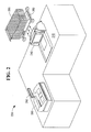
- Fig. 2 illustrates a checkout system 200 including a scanner and scale unit 210 integrated into a checkout stand 240 where the scanner 210 is utilized in conjunction with a point of sale terminal 260 by a cashier to checkout a customer's purchases such as groceries and the like which are brought to the checkout stand, for example, in a cart, such as illustrated 280.
- the checkout system 200 is used in a typical manner in which the cashier or the customer places items to be purchased on a top surface of checkout stand 240.
- the cashier scans barcodes on the items by passing them through the scan zones of the scanner 210, and places them on a conveyer that takes the scanned items to a bagging area. This conveyer and bagging portions of checkout stand 240 are shown partly cutaway so as not to block the view of the bottom of cart 280.
- the imaging system of scanner and scale unit 210 also captures an image of the bottom of cart 280 utilizing a single optical system.
- the image of the bottom of the cart can be fed to cashier display 262 of the POS terminal 260. Further details of such operation are discussed below in connection with Figs. 3 and 4 .
- the imaging system of the scanner and scale unit 210 may be manually switched from cashier side for scanning of items to be purchased to the customer side as shown in Fig. 3 or automatically switched as discussed in connection with Figs. 5A-5D and Fig. 6 .
- FIG. 3 shows a block diagram of a bi-optic scanner 300 which may suitably be implemented by scanner 100 or checkout system 200.
- barcode imaging lines 310 are shown for a cashier side vertical field of view.
- a mechanical image controller 320 is utilized by a cashier to change from the cashier side vertical field of view to either a near customer field of view where imaging lines represented by line 315 in Fig. 3 sense customer presentation of an item, such as customer cell phone 330, or lines 325 obtain image data for a far customer field of view, such as bottom of cart 340.
- imaging lines represented by line 315 in Fig. 3 sense customer presentation of an item, such as customer cell phone 330, or lines 325 obtain image data for a far customer field of view, such as bottom of cart 340.
- mechanical image controller 310 is illustrated as a rotatable lever arm which controls positioning of a mirror face 322 to allow a cashier to manually change the field of view.
- An illuminator such as illuminator 144 of Fig. 1 may be employed to provide the cashier with an imaging guide. It will be apparent to those of ordinary skill in the art that a circular rotatable handle or a wide range of other mechanical arrangements may be suitably used as an alternative thereto. Additionally, a cashier operated switch could suitably be employed, or as described in connection with Figs. 5A-5D and Fig. 6 , an automatic field of view switching arrangement may be advantageously employed.
- FIG. 4 an exemplary cashier LCD display 462 is shown in which items purchased and their prices 464 are displayed in a normal manner along with video feed 466 from either the near customer field of view for customer cellphone 330 of Fig. 3 or the far customer field of view for bottom of cart 340 of Fig. 3 .
- This video feed 466 can advantageously be flashing to draw cashier attention or highlighted in an eye catching color such as red, for example. In this way, the cashier is much less likely to miss an item on the bottom of the cart or fail to check a customer identification.
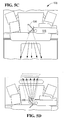
- the present invention recognizes that it may be advantageous to provide an automatic arrangement for switching from a cashier field of view 510 for a fixed imager 515 ( Fig. 5E ) for scanner 500 as illustrated in Fig. 5A to a customer side field of view 520 as illustrated in Fig. 5B .
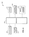
- a photodetector which may suitably comprise one or more photodiodes, such as photodetector 602 of Fig. 6 , is built into the scanner 500.
- this presented item tends to reduce the light reaching the photodiode 602.
- the customer presents a bar coded item, such as a coupon, by placing it directly against a customer presentation window 525 seen in Fig. 5B .
- a level change is detected, for example, by programmed microprocessor 610 of control circuit 600 of Fig. 6 .
- the microprocessor 610 controls an automatic switch from cashier field of view to customer side field of view 520 of Fig. 5B .
- microprocessor 610 drives an actuator 616, such as a small motor or solenoid to move a mirror arrangement 530 from a first position illustrated in Fig. 5C to a second position illustrated in Fig. 5D .
- This movement can be a simple linear movement as shown in Figs. 5C and 5D or a rotational movement not shown.
- a green LED or other indicator such as an aural indicator
- the processor 600 Upon successful reading of a barcode, a green LED or other indicator, such as an aural indicator, can be controllably driven by the processor 600 to provide the customer with feedback that the item has been successfully presented and can now be put away.
- Figs. 5A-5D and 6 has the advantage that no cashier training is required and no control buttons need to be added to the scanner 500.
- Control circuit 600 includes a programmed processor 610 having a program 612 comprising a sequence of software instructions stored in memory 614.
- the processor 610 receives as an input, the output of the photodetector 602.
- the processor drives an actuator 616 to automatically control a change of the field of view.
- processor 610 may drive a successful read indicator 620, such as a green LED, letting the customer know the phone can now be removed.
- the processor 600 also drives the actuator 616 to return the imager to the cashier field of view.
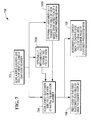
- Fig. 7 illustrates a process 700 in accordance with the present invention.
- a bar code scanner scans a first cashier side field of view.
- the bar code scanner proceeds to scan a first customer side field of view. While this process may proceed directly as in Fig. 1 as a result of rotation of mirrored spinner 122 and the other optical elements, in an optional step 703A, the process proceeds as a result of a mechanical adjustment by the cashier as addressed in connection with Fig. 3 . In an optional step 703B, the process proceeds as a result of an automatic optical adjustment triggered by detection of a customer presenting an item at a customer presentation window as addressed in connection with Figs. 5A-5D and Fig. 6 .
- step 706 video thereof may be suitably fed to a cashier display device, such as the display of a point of sale terminal like display 262 of the terminal 260.
- step 708 where a bar code from a display of a cell phone, for example, is successfully read, an automatic switch back to a cashier field of view occurs.
Landscapes
- Physics & Mathematics (AREA)
- Electromagnetism (AREA)
- Engineering & Computer Science (AREA)
- General Physics & Mathematics (AREA)
- Health & Medical Sciences (AREA)
- General Health & Medical Sciences (AREA)
- Toxicology (AREA)
- Artificial Intelligence (AREA)
- Computer Vision & Pattern Recognition (AREA)
- Theoretical Computer Science (AREA)
- Cash Registers Or Receiving Machines (AREA)
Abstract
Description
- The present invention relates generally to improvements in bar code scanning, and more particularly to improved methods and apparatus for providing both cashier and customer side imaging.
- Image based bar code scanning is a known technique. See, for example,
U.S. Patent Application Serial No. 12/342,792, filed December 23, 2008 U.S. Patent Application Publication No. 2010/0155484 . Such approaches provide valuable techniques for obtaining images of bar codes on items at checkout at grocery, retail stores and the like. However, the imager employed typically obtains images from the cashier side of a checkout stand and not from the customer side. Thus, if a customer has a bar coded loyalty card, the customer hands the card to the store checkout person or cashier who scans it and then returns it to the customer. - Another and different aspect of checkout is that shoppers often place large or bulky items, such as a large bag of dog food, kitty litter, potatoes, a twelve pack of carbonated drinks cans or the like on the bottom rack of the traditional shopping cart which is designed to support such items. However, when checking out customers rapidly, the bottom of the cart items can be missed, or alternatively may require a time consuming process to be scanned. As one alternative, the large bulky items must be boosted to the checkout surface and scanned. As another alternative, the service person may need to come around the customer side and scan the item or items with a handheld scanner.
- It is also known to capture a video feed of the vicinity of a checkout station. See, for example,
U.S. Patent Application Serial No. 11/835,578, filed August 8, 2007 U.S. Patent Application Publication No. 2009/0039165 . This approach employs a separate camera to capture the video feed. - Among its several aspects, the present invention recognizes that situations like those described above can be handled more efficiently without adding a significant amount of new imaging hardware by adapting existing bar code imaging optics to also perform a customer side imaging function or functions.
- According to a first aspect of the present invention there is provided an image based bar code scanner having a cashier side and a customer side, as set forth in claim 1.
- According to a second aspect of the present invention there is provided a method of image based bar code scanning utilizing a bar code scanner, as set forth in claim 9.
- As an example, more and more cell phone users are employing applications to scan customer loyalty codes into their cell phones so that when they want to use the loyalty code, they simply select an icon on the phone and a corresponding bar code is displayed, thereby eliminating the need to carry a key ring or wallet full of loyalty cards. However, unlike a key ring or card which the customer feels comfortable handing to a checkout clerk, the customer may not want other people handling his or her phone for a wide variety of reasons ranging from personal hygiene related to personal privacy concerns, and the like. One aspect of the present invention allows the customer to maintain control of the phone while presenting a displayed bar code for scanning on the customer side as addressed further below. Further, in another aspect of the invention, customer presentation of a cell phone, license, a coupon, or the like, may be automatically sensed, and bar code imaging optics may be automatically switched from cashier side to customer side as addressed further herein.
- As a further example, a customer may be requested to produce a valid identification, such as a driver's license, to purchase products such as tobacco products or alcoholic beverages. Also, a driver's license may be requested in connection with the use of a credit card, debit card or the like. An aspect of the present invention allows the customer to present identification on the customer side.
- As a further example, another aspect of the present invention allows a video image from the customer side, such as video of any bulky articles on the bottom shelf of a grocery cart, to be displayed on a checkout display so the checkout person does not inadvertently miss such items. Recognition software can suitably analyze such video and the display can be flashed, highlighted or the checkout person's attention can otherwise be directed thereto.
- A more complete understanding of the present invention, as well as further features and advantages of the invention, will be apparent from the following specific description, given by way of example, with reference to the accompanying drawings, in which:
-
Fig. 1 illustrates an imaging bar code scanner providing both cashier side and customer side fields of view in accordance with the present invention; -
Fig. 2 illustrates an imaging bar code scanner, such as the scanner ofFig. 1 employed to detect items on a bottom shelf of a shopping cart; -
Fig. 3 illustrates a manual arrangement for a cashier to change the field of view of an imaging barcode scanner in accordance with the present invention; -
Fig. 4 illustrates video feed displayed on a cashier display captured by the imaging barcode scanner ofFig. 3 , for example; -
Figs. 5A-5D illustrate aspects of an automatic sensing embodiment for changeover from cashier side imaging to customer side imaging in accordance with the present amendment; -
Fig. 6 illustrates a control circuit arrangement for use in connection with the embodiment ofFigs. 5A-5D ; and -
Fig. 7 illustrates a process of cashier and customer imaging in accordance with the present invention. - Reference is first made to
Fig. 1 , which illustrates an image basedbar code scanner 100 according to one embodiment of the present invention. Thescanner 100 includes ahousing 102, horizontal andvertical scan windows imaging device 108. Theimaging device 108 uses animaging element 109 to capture digital images of objects placed within either of horizontal orvertical scan volumes imaging device 108, such as aprocessor 114,memory 115, andstorage 116. -
Scanner 100 further includes aprocessor 117,memory 118, and long term storage such asflash memory 119, communicating with one another and with theimaging device 108 over abus 120. Images fromscan volumes - Additionally, an image through a customer side scan window 107 (also referred to as customer presentation window) for a
further scan volume 113, is also captured byimaging element 109. This image is referred to here as a customer side image. The customer side image will typically be of a customer identification card, a loyalty card, a barcode displayed on a cell phone display, or the like, collectively, acustomer item 125. - In order to provide for increased operator convenience and efficiency, as well as flexibility and economy in scanner design, the
scanner 100 includes optical elements to direct images of bar codes to the scanner along desired pathways, with these pathways being changed in predetermined ways. Such use of optical elements allows for an increase in the size of thescan volumes scan volume 113. This use of optical elements allows for economy in the use of imaging devices, because oneimaging device 108 can be used to capture images of bar codes presented at either of thescan windows customer item 125 presented at thecustomer presentation window 107, and also allows for flexibility in scanner design. Rather than placing an imaging device such as theimaging device 108 to have a direct view of a scan window such as thescan window 104, an imaging device can be placed at any location to which it is suitable to direct an image through the placement of optical elements. The optical elements include a rotatingspinner 122, rotated by amotor 124. - The
scanner 100 further includes a sequence offixed mirrors fixed mirror 126 receives a reflection from abar code 132 positioned in thescan volume 110, and directs the reflection to thespinner 122. The spinner in turn directs the reflection along the sequence ofmirrors imaging device 108. Thespinner 122 suitably has four differently angled facets, so that the facets reflect incident light at different angles. As thespinner 122 rotates, the position of each facet changes, so that the field of view encompassed by the facet changes. In addition, the angle of incidence of light striking thespinner 122 changes, so that light originating from the same point strikes and leaves the facet at a constantly changing angle. The effect of the rotation of thespinner 122 is therefore to capture and reflect light, and therefore images of objects from which the light is reflected, from different origins, and to present images which translate through space with the rotation of the spinner. An image of thebar code 132 will therefore come into the field of view of thespinner 122 and will move along a pathway that takes it into the field of view of theimaging device 108, and this will occur for numerous positions and orientations of thebar code 132 in thescan volume 110. - Similarly, the
scanner 100 includes a sequence of mirrors 134,136,138,140 providing one pathway for reflection of an image entering thescan window 106. An image of thebar code 142 enters thescan window 106, and is directed from themirror 134, to thespinner 122, to themirrors imaging device 108. The reflected image of thebar code 142 is translated by the rotation of thespinner 122 so that it is directed to theimaging device 108 at some point during the rotation of thespinner 122. - The movement of the field of view, and shifts between different fields of view, may be relatively rapid, so as to quickly encompass many different locations in the
scan zones bar code 132 or thebar code 142, if held in approximately one position, may be in the field of view of the scanner for only a relatively short time during each rotation of thespinner 122. For this reason, the processing elements of thescanner 100, such as theimaging element 109,processor 114,memory 115, andstorage 116, and theprocessor 117,memory 118, andstorage 119, are suitably chosen so as to operate at a high speed to allow for rapid image capture and processing and, if desired, to allow for numerous rapid captures of an image as thespinner 122 rotates repeatedly through the same rotational position. - The
scanner 100 also includes a sequence of mirrors, 139, 140, which directs an image fromscan volume 113, entering throughcustomer presentation window 107 inface 143 of thehousing 102 to theimaging device 108. It will be recognized that while a very simple image collecting optical arrangement is illustrated inFIG. 1 for collecting images fromscan volume 113 that other more complex arrangements may be suitably employed particularly where a larger or different scan volume is to be dealt with as addressed further below. Theimaging device 108 may also suitably include anilluminator 144, which illuminates thescan volumes illuminator 144 may emit infrared or visible light, and is suitably positioned and oriented to provide on-axis illumination. On-axis illumination is less irritating to an operator or customer but can be expected to introduce reflection and noise. Theimaging device 108 therefore suitably includes appropriate optical or digital filtering and compensation, and the data processing elements of thescanner 100 are suitably programmed so as to reduce or eliminate noise and other effects introduced by such illumination that tend to degrade imaging accuracy and the efficiency of decoding. Theilluminator 144 directs an illumination beam 146 out of theimaging device 108 in the opposite direction from incoming light rays. The path of the illumination beam 146 is directed by thespinner 122 and the fixed mirrors so that it illuminates the field of view of thescanner 100 at any particular time. For example, when thespinner 122 is positioned so that an image of thebar code 142 is directed to theimaging device 108, the positioning of the spinner also serves to direct the illumination beam to illuminate thebar code 142. -
Fig. 2 illustrates acheckout system 200 including a scanner andscale unit 210 integrated into acheckout stand 240 where thescanner 210 is utilized in conjunction with a point ofsale terminal 260 by a cashier to checkout a customer's purchases such as groceries and the like which are brought to the checkout stand, for example, in a cart, such as illustrated 280. Thecheckout system 200 is used in a typical manner in which the cashier or the customer places items to be purchased on a top surface ofcheckout stand 240. The cashier scans barcodes on the items by passing them through the scan zones of thescanner 210, and places them on a conveyer that takes the scanned items to a bagging area. This conveyer and bagging portions of checkout stand 240 are shown partly cutaway so as not to block the view of the bottom ofcart 280. - Unlike typical prior art checkout systems, in
checkout system 200, the imaging system of scanner andscale unit 210 also captures an image of the bottom ofcart 280 utilizing a single optical system. The image of the bottom of the cart can be fed tocashier display 262 of thePOS terminal 260. Further details of such operation are discussed below in connection withFigs. 3 and 4 . Additionally, if the customer wishes to present a coupon or loyalty code loaded on a cell phone, a driver's license for identification or the like, the imaging system of the scanner andscale unit 210 may be manually switched from cashier side for scanning of items to be purchased to the customer side as shown inFig. 3 or automatically switched as discussed in connection withFigs. 5A-5D andFig. 6 . - Turning to
Fig. 3 , this figure shows a block diagram of abi-optic scanner 300 which may suitably be implemented byscanner 100 orcheckout system 200. InFig. 3 ,barcode imaging lines 310 are shown for a cashier side vertical field of view. Amechanical image controller 320 is utilized by a cashier to change from the cashier side vertical field of view to either a near customer field of view where imaging lines represented byline 315 inFig. 3 sense customer presentation of an item, such ascustomer cell phone 330, orlines 325 obtain image data for a far customer field of view, such as bottom ofcart 340. InFig. 3 ,mechanical image controller 310 is illustrated as a rotatable lever arm which controls positioning of amirror face 322 to allow a cashier to manually change the field of view. An illuminator, such asilluminator 144 ofFig. 1 may be employed to provide the cashier with an imaging guide. It will be apparent to those of ordinary skill in the art that a circular rotatable handle or a wide range of other mechanical arrangements may be suitably used as an alternative thereto. Additionally, a cashier operated switch could suitably be employed, or as described in connection withFigs. 5A-5D andFig. 6 , an automatic field of view switching arrangement may be advantageously employed. - Turning to
Fig. 4 , an exemplarycashier LCD display 462 is shown in which items purchased and theirprices 464 are displayed in a normal manner along withvideo feed 466 from either the near customer field of view forcustomer cellphone 330 ofFig. 3 or the far customer field of view for bottom ofcart 340 ofFig. 3 . This video feed 466 can advantageously be flashing to draw cashier attention or highlighted in an eye catching color such as red, for example. In this way, the cashier is much less likely to miss an item on the bottom of the cart or fail to check a customer identification. - As shown in
Figs. 5A-5D and 6 , among its several aspects, the present invention recognizes that it may be advantageous to provide an automatic arrangement for switching from a cashier field ofview 510 for a fixed imager 515 (Fig. 5E ) forscanner 500 as illustrated inFig. 5A to a customer side field ofview 520 as illustrated inFig. 5B . To this end, a photodetector which may suitably comprise one or more photodiodes, such asphotodetector 602 ofFig. 6 , is built into thescanner 500. When a customer presents a cell phone, a coupon, an identification card or the like, this presented item tends to reduce the light reaching thephotodiode 602. In one embodiment, the customer presents a bar coded item, such as a coupon, by placing it directly against acustomer presentation window 525 seen inFig. 5B . When the light level falls below a predetermined threshold, a level change is detected, for example, byprogrammed microprocessor 610 ofcontrol circuit 600 ofFig. 6 . Under control of a program, such asprogram 612 stored inmemory 614 ofFig. 6 , themicroprocessor 610 controls an automatic switch from cashier field of view to customer side field ofview 520 ofFig. 5B . - As one example,
microprocessor 610 drives anactuator 616, such as a small motor or solenoid to move amirror arrangement 530 from a first position illustrated inFig. 5C to a second position illustrated inFig. 5D . This movement can be a simple linear movement as shown inFigs. 5C and 5D or a rotational movement not shown. - Upon successful reading of a barcode, a green LED or other indicator, such as an aural indicator, can be controllably driven by the
processor 600 to provide the customer with feedback that the item has been successfully presented and can now be put away. - Among its several advantages, the approach of
Figs. 5A-5D and6 has the advantage that no cashier training is required and no control buttons need to be added to thescanner 500. - Turning to
Fig. 6 , anillustrative control circuit 600 is shown for use in conjunction with thescanner 500 ofFig. 5 .Control circuit 600 includes a programmedprocessor 610 having aprogram 612 comprising a sequence of software instructions stored inmemory 614. Theprocessor 610 receives as an input, the output of thephotodetector 602. Upon detecting a drop in illumination as a result of the customer positioning an item such as a cell phone next tocustomer presentation window 525 ofFig. 5B , the processor drives anactuator 616 to automatically control a change of the field of view. Optionally, upon successful read ofbar code data 618, such as a barcode displayed on the display of the cell phone,processor 610 may drive asuccessful read indicator 620, such as a green LED, letting the customer know the phone can now be removed. Theprocessor 600 also drives theactuator 616 to return the imager to the cashier field of view. -
Fig. 7 illustrates aprocess 700 in accordance with the present invention. Instep 702, a bar code scanner scans a first cashier side field of view. Instep 704, the bar code scanner proceeds to scan a first customer side field of view. While this process may proceed directly as inFig. 1 as a result of rotation of mirroredspinner 122 and the other optical elements, in anoptional step 703A, the process proceeds as a result of a mechanical adjustment by the cashier as addressed in connection withFig. 3 . In anoptional step 703B, the process proceeds as a result of an automatic optical adjustment triggered by detection of a customer presenting an item at a customer presentation window as addressed in connection withFigs. 5A-5D andFig. 6 . - Where the field of view is a bottom of the cart field of view, for example, in
step 706, video thereof may be suitably fed to a cashier display device, such as the display of a point of sale terminal likedisplay 262 of the terminal 260. - Where the field of view is of a volume adjacent the customer presentation window, in
step 708, where a bar code from a display of a cell phone, for example, is successfully read, an automatic switch back to a cashier field of view occurs. - While the present invention is disclosed in the context of a presently preferred embodiment, it will be recognized that a wide variety of implementations may be employed by persons of ordinary skill in the art within the scope of the following claims.
Claims (12)
- An image based bar code scanner (100) having a cashier side and a customer side, the image based bar code scanner (100) comprising:an imaging device (108) for capturing an image of a bar code (132 or 142) presented by a cashier within a cashier field of view (110, 112) on the cashier side;a rotating multifaceted mirrored spinner (122) for reflecting an image of the bar code (132 or 142), with the rotating spinner (122) being positioned and oriented such that a field of view (110 or 112) of the scanner (100) encompasses images of the bar code (132 or 142) reflected by the spinner (122) to the imaging device (108) and such that the rotation of the spinner (122) acts to provide the imaging device (108) with a changing field of view, wherein the field of view of the scanner (100) is changed to a customer side field of view (113) and the imaging device (108) then captures an image from the customer side.
- The image based scanner of claim 1, further comprising one or more sets of fixed mirrors (126, 128, 130, 136, 138, 139 or 140) positioned and oriented such the fields of view of the imaging device (108) are positioned and oriented such that the rotation of the spinner (122) causes the field of view (110 or 112) of the scanner (100) to shift between a vertical scan window (106) and a horizontal scan window (104) on the cashier side.
- The image based bar code scanner of claim 1, further comprising an illuminator (144) directing an illumination beam (146) such that the beam (146) is reflected from the spinner (122) to illuminate the field of view (110, 112, 113) of the scanner (100).
- The image based bar code scanner of claim 3, wherein the scanner (100) includes filtering to reduce noise introduced by on-axis illumination from the illuminator (144).
- The image based bar code scanner any preceding claim, further comprising:a customer presentation window (107); anda detector (602) to detect an item (125) presented by a customer at the customer presentation window (107).
- The image based bar code scanner of claim 5 further comprising:an actuator (616) to move a mirror arrangement (530); anda controller (610) to drive the actuator (616) in response to detection of the item (125) presented by the customer to switch the field of view to the customer side.
- The image based bar code scanner of any preceding claim, wherein the customer side field of view (113) includes a bottom (340) of a customer cart (280) on the customer side.
- The image based bar code scanner of claim 7, wherein the imaging device (108) captures video of the bottom (340) of the customer cart (280) and provides that video to a cashier display (462).
- The image based bar code scanner of any preceding claim, further comprising:a cashier actuated mechanical actuator (320) for manually switching from the cashier field of view (113) to the customer side field of view (110 or 112).
- A method of image based bar code scanning utilizing a bar code scanner (100) comprising the steps of:activating a rotating mirrored spinner (122) so that a field of view of the bar code image scanner (100) encompasses images of a first bar code (132 or 142) reflected by the spinner (122) to the imaging device (108), the bar code (132 or 142) being presented by a cashier on a cashier side of the bar code scanner (100); andchanging the field of view (110, 112, 113) of the bar code image scanner (100) to encompass a second bar code presented by a customer at a customer presentation window (107) on the customer side.
- The method of claim 10, wherein the cashier field of view (110 or 112) of the bar code image scanner (100) shifts with the rotation of the spinner (122) between a horizontal scan window (104) and a vertical scan window (106).
- The method of claim 10 or 11, further comprising directing an illumination beam (146) such that the beam (146) is reflected from the rotating spinner (122) so as to illuminate the fields of view (110, 112 or 113) of the bar code image scanner (100).
Applications Claiming Priority (1)
| Application Number | Priority Date | Filing Date | Title |
|---|---|---|---|
| US13/222,003 US8496178B2 (en) | 2011-08-31 | 2011-08-31 | Method and apparatus for providing customer side imaging as well as bar code scanning imaging |
Publications (2)
| Publication Number | Publication Date |
|---|---|
| EP2565819A1 true EP2565819A1 (en) | 2013-03-06 |
| EP2565819B1 EP2565819B1 (en) | 2014-09-24 |
Family
ID=46754245
Family Applications (1)
| Application Number | Title | Priority Date | Filing Date |
|---|---|---|---|
| EP12175085.5A Active EP2565819B1 (en) | 2011-08-31 | 2012-07-05 | Method and apparatus for providing customer side imaging as well as bar code scanning imaging |
Country Status (3)
| Country | Link |
|---|---|
| US (1) | US8496178B2 (en) |
| EP (1) | EP2565819B1 (en) |
| CN (1) | CN103177234B (en) |
Cited By (3)
| Publication number | Priority date | Publication date | Assignee | Title |
|---|---|---|---|---|
| WO2014158591A1 (en) * | 2013-03-12 | 2014-10-02 | Symbol Technologies, Inc. | Apparatus for, and method of, electro- optically reading targets by enabling a customer to move a customer-operated accessory reader supported by a clerk- operated workstation of a checkout system |
| EP2693365A3 (en) * | 2012-07-31 | 2017-04-12 | NCR Corporation | Scanning optical codes |
| GB2581757A (en) * | 2017-12-18 | 2020-08-26 | Symbol Technologies Llc | Bi-optic barcode reader |
Families Citing this family (13)
| Publication number | Priority date | Publication date | Assignee | Title |
|---|---|---|---|---|
| US8590789B2 (en) * | 2011-09-14 | 2013-11-26 | Metrologic Instruments, Inc. | Scanner with wake-up mode |
| US8678274B1 (en) * | 2012-08-30 | 2014-03-25 | Symbol Technologies, Inc. | Point-of-transaction checkout system for and method of processing targets electro-optically readable by a clerk-operated workstation and by a customer-operated accessory reader |
| USD723560S1 (en) * | 2013-07-03 | 2015-03-03 | Hand Held Products, Inc. | Scanner |
| CN103714308A (en) * | 2013-12-07 | 2014-04-09 | 苏州斯普锐智能系统有限公司 | Barcode scanning device having temperature-regulating module |
| USD730901S1 (en) * | 2014-06-24 | 2015-06-02 | Hand Held Products, Inc. | In-counter barcode scanner |
| US9501677B2 (en) * | 2014-08-18 | 2016-11-22 | Datalogic ADC, Inc. | Data entry device with enhanced aiming |
| US10445714B2 (en) * | 2015-01-29 | 2019-10-15 | Ncr Corporation | Gesture-based signature capture |
| CN106023482A (en) * | 2015-03-26 | 2016-10-12 | 东芝泰格有限公司 | Reading apparatus and POS system |
| JP6272795B2 (en) * | 2015-03-26 | 2018-01-31 | 東芝テック株式会社 | Reader |
| US20170053252A1 (en) * | 2015-08-20 | 2017-02-23 | Bank Of America Corporation | Single in-line biometric automatic teller machine ("atm") session maintenance using biometric characteristic |
| US10007824B1 (en) | 2016-12-23 | 2018-06-26 | Datalogic Usa, Inc. | Target options for a data capture device with intuitive aiming involving specular objects |
| US11100331B2 (en) * | 2019-01-23 | 2021-08-24 | Everseen Limited | System and method for detecting scan irregularities at self-checkout terminals |
| WO2021124584A1 (en) * | 2019-12-20 | 2021-06-24 | 富士通フロンテック株式会社 | Paper storage device, product registration method and product registration program |
Citations (5)
| Publication number | Priority date | Publication date | Assignee | Title |
|---|---|---|---|---|
| WO2003062956A2 (en) * | 2002-01-16 | 2003-07-31 | Metrologic Instruments, Inc. | Point of sale (pos) based bar code reading and cash register systems with integrated internet-enabled customer-kiosk terminals |
| US20050224583A1 (en) * | 1996-01-31 | 2005-10-13 | Psc Scanning, Inc. | Multiple aperture data reader for multi-mode operation |
| US20090039165A1 (en) | 2007-08-08 | 2009-02-12 | Ncr Corporation | Methods and Apparatus for a Bar Code Scanner Providing Video Surveillance |
| US20100155484A1 (en) | 2008-12-23 | 2010-06-24 | Ncr Corporation | Methods and Apparatus for Providing a Changing Field of View in Image Based Bar Code Scanning |
| WO2011159429A1 (en) * | 2010-06-16 | 2011-12-22 | Symbol Technologies, Inc. | Optical scanner with customer interface |
Family Cites Families (12)
| Publication number | Priority date | Publication date | Assignee | Title |
|---|---|---|---|---|
| DE69021495T2 (en) * | 1989-10-16 | 1996-01-04 | Fujitsu Ltd | Article sensing device and method for determining the article. |
| US5073702A (en) * | 1990-03-26 | 1991-12-17 | Ncr Corporation | Multiple beam bar code scanner |
| US5475207A (en) * | 1992-07-14 | 1995-12-12 | Spectra-Physics Scanning Systems, Inc. | Multiple plane scanning system for data reading applications |
| JP3580676B2 (en) * | 1997-08-01 | 2004-10-27 | 富士通株式会社 | Optical scanning device and light source module |
| US6427915B1 (en) * | 1999-11-02 | 2002-08-06 | Ncr Corporation | Method of operating checkout system having modular construction |
| US20030132291A1 (en) * | 2002-01-11 | 2003-07-17 | Metrologic Instruments, Inc. | Point of sale (POS) station having bar code reading system with integrated internet-enabled customer-kiosk terminal |
| US8042740B2 (en) * | 2000-11-24 | 2011-10-25 | Metrologic Instruments, Inc. | Method of reading bar code symbols on objects at a point-of-sale station by passing said objects through a complex of stationary coplanar illumination and imaging planes projected into a 3D imaging volume |
| US6631845B2 (en) * | 2001-04-03 | 2003-10-14 | Symbol Technologies, Inc. | Two window optical scanner |
| US20060038009A1 (en) * | 2002-01-11 | 2006-02-23 | Metrologic Instruments, Inc. | Point of sale (POS) based bar code reading and cash register systems with integrated internet-enabled customer-kiosk terminals |
| US6974083B1 (en) * | 2004-07-23 | 2005-12-13 | Symbol Technologies, Inc. | Point-of-transaction workstation for electro-optically reading one-dimensional indicia, including image capture of two-dimensional targets |
| US7380719B1 (en) * | 2006-09-21 | 2008-06-03 | Ncr Corporation | Barcode scanner with configurable video modes |
| US9542582B2 (en) * | 2009-04-24 | 2017-01-10 | Datalogic ADC, Inc. | System and method for multi-view imaging of optical codes using chromatic path splitting |
-
2011
- 2011-08-31 US US13/222,003 patent/US8496178B2/en active Active
-
2012
- 2012-07-05 EP EP12175085.5A patent/EP2565819B1/en active Active
- 2012-08-29 CN CN201210311374.6A patent/CN103177234B/en active Active
Patent Citations (6)
| Publication number | Priority date | Publication date | Assignee | Title |
|---|---|---|---|---|
| US20050224583A1 (en) * | 1996-01-31 | 2005-10-13 | Psc Scanning, Inc. | Multiple aperture data reader for multi-mode operation |
| WO2003062956A2 (en) * | 2002-01-16 | 2003-07-31 | Metrologic Instruments, Inc. | Point of sale (pos) based bar code reading and cash register systems with integrated internet-enabled customer-kiosk terminals |
| US20090039165A1 (en) | 2007-08-08 | 2009-02-12 | Ncr Corporation | Methods and Apparatus for a Bar Code Scanner Providing Video Surveillance |
| US20100155484A1 (en) | 2008-12-23 | 2010-06-24 | Ncr Corporation | Methods and Apparatus for Providing a Changing Field of View in Image Based Bar Code Scanning |
| EP2202668A1 (en) * | 2008-12-23 | 2010-06-30 | NCR Corporation | Methods and apparatus for providing a changing field of view in image based bar code scanning |
| WO2011159429A1 (en) * | 2010-06-16 | 2011-12-22 | Symbol Technologies, Inc. | Optical scanner with customer interface |
Cited By (5)
| Publication number | Priority date | Publication date | Assignee | Title |
|---|---|---|---|---|
| EP2693365A3 (en) * | 2012-07-31 | 2017-04-12 | NCR Corporation | Scanning optical codes |
| WO2014158591A1 (en) * | 2013-03-12 | 2014-10-02 | Symbol Technologies, Inc. | Apparatus for, and method of, electro- optically reading targets by enabling a customer to move a customer-operated accessory reader supported by a clerk- operated workstation of a checkout system |
| GB2581757A (en) * | 2017-12-18 | 2020-08-26 | Symbol Technologies Llc | Bi-optic barcode reader |
| GB2581757B (en) * | 2017-12-18 | 2021-02-24 | Symbol Technologies Llc | Bi-optic barcode reader |
| AU2020277149B2 (en) * | 2017-12-18 | 2022-10-27 | Symbol Technologies, Llc | Bi-optic barcode reader |
Also Published As
| Publication number | Publication date |
|---|---|
| CN103177234A (en) | 2013-06-26 |
| CN103177234B (en) | 2016-08-31 |
| US20130048732A1 (en) | 2013-02-28 |
| US8496178B2 (en) | 2013-07-30 |
| EP2565819B1 (en) | 2014-09-24 |
Similar Documents
| Publication | Publication Date | Title |
|---|---|---|
| EP2565819B1 (en) | Method and apparatus for providing customer side imaging as well as bar code scanning imaging | |
| US12223810B2 (en) | Bioptical barcode reader | |
| CA2882883C (en) | Checkout system for and method of preventing a customer-operated accessory reader facing a bagging area from imaging targets on products passed through a clerk-operated workstation to the bagging area | |
| US8079523B2 (en) | Imaging of non-barcoded documents | |
| US8740075B2 (en) | Apparatus for and method of reading targets arbitrarily oriented in imaging workstations | |
| US8870073B2 (en) | Methods and apparatus for positioning an optical code for imaging scanning | |
| US8939371B2 (en) | Individual exposure control over individually illuminated subfields of view split from an imager in a point-of-transaction workstation | |
| EP2575073B1 (en) | Control of an imaging scanner | |
| US8991705B2 (en) | Apparatus for, and method of, electro-optically reading targets by enabling a customer to move a customer-operated accessory reader supported by a clerk-operated workstation of a checkout system | |
| US8678274B1 (en) | Point-of-transaction checkout system for and method of processing targets electro-optically readable by a clerk-operated workstation and by a customer-operated accessory reader | |
| KR20220056443A (en) | Unmanned checkout counter | |
| US8960551B2 (en) | Method of decoding barcode with imaging scanner having multiple object sensors | |
| US8727218B1 (en) | Symmetric customer side scanner for bioptic rear tower | |
| US9747485B2 (en) | Arrangement for and method of cleaning a platter of a product checkout workstation | |
| EP3281159B1 (en) | Arrangement for and method of assessing efficiency of transactions involving products associated with electro-optically readable targets | |
| US8511559B2 (en) | Apparatus for and method of reading targets by image captured by processing captured target images in a batch or free-running mode of operation |
Legal Events
| Date | Code | Title | Description |
|---|---|---|---|
| PUAI | Public reference made under article 153(3) epc to a published international application that has entered the european phase |
Free format text: ORIGINAL CODE: 0009012 |
|
| AK | Designated contracting states |
Kind code of ref document: A1 Designated state(s): AL AT BE BG CH CY CZ DE DK EE ES FI FR GB GR HR HU IE IS IT LI LT LU LV MC MK MT NL NO PL PT RO RS SE SI SK SM TR |
|
| AX | Request for extension of the european patent |
Extension state: BA ME |
|
| 17P | Request for examination filed |
Effective date: 20130906 |
|
| RBV | Designated contracting states (corrected) |
Designated state(s): AL AT BE BG CH CY CZ DE DK EE ES FI FR GB GR HR HU IE IS IT LI LT LU LV MC MK MT NL NO PL PT RO RS SE SI SK SM TR |
|
| GRAP | Despatch of communication of intention to grant a patent |
Free format text: ORIGINAL CODE: EPIDOSNIGR1 |
|
| INTG | Intention to grant announced |
Effective date: 20140707 |
|
| GRAS | Grant fee paid |
Free format text: ORIGINAL CODE: EPIDOSNIGR3 |
|
| GRAA | (expected) grant |
Free format text: ORIGINAL CODE: 0009210 |
|
| REG | Reference to a national code |
Ref country code: DE Ref legal event code: R084 Ref document number: 602012003180 Country of ref document: DE |
|
| AK | Designated contracting states |
Kind code of ref document: B1 Designated state(s): AL AT BE BG CH CY CZ DE DK EE ES FI FR GB GR HR HU IE IS IT LI LT LU LV MC MK MT NL NO PL PT RO RS SE SI SK SM TR |
|
| REG | Reference to a national code |
Ref country code: GB Ref legal event code: FG4D |
|
| REG | Reference to a national code |
Ref country code: CH Ref legal event code: EP |
|
| REG | Reference to a national code |
Ref country code: AT Ref legal event code: REF Ref document number: 688910 Country of ref document: AT Kind code of ref document: T Effective date: 20141015 |
|
| REG | Reference to a national code |
Ref country code: IE Ref legal event code: FG4D |
|
| REG | Reference to a national code |
Ref country code: GB Ref legal event code: 746 Effective date: 20141015 |
|
| REG | Reference to a national code |
Ref country code: DE Ref legal event code: R096 Ref document number: 602012003180 Country of ref document: DE Effective date: 20141106 Ref country code: DE Ref legal event code: R084 Ref document number: 602012003180 Country of ref document: DE Effective date: 20140917 |
|
| PG25 | Lapsed in a contracting state [announced via postgrant information from national office to epo] |
Ref country code: NO Free format text: LAPSE BECAUSE OF FAILURE TO SUBMIT A TRANSLATION OF THE DESCRIPTION OR TO PAY THE FEE WITHIN THE PRESCRIBED TIME-LIMIT Effective date: 20141224 Ref country code: SE Free format text: LAPSE BECAUSE OF FAILURE TO SUBMIT A TRANSLATION OF THE DESCRIPTION OR TO PAY THE FEE WITHIN THE PRESCRIBED TIME-LIMIT Effective date: 20140924 Ref country code: GR Free format text: LAPSE BECAUSE OF FAILURE TO SUBMIT A TRANSLATION OF THE DESCRIPTION OR TO PAY THE FEE WITHIN THE PRESCRIBED TIME-LIMIT Effective date: 20141225 Ref country code: LT Free format text: LAPSE BECAUSE OF FAILURE TO SUBMIT A TRANSLATION OF THE DESCRIPTION OR TO PAY THE FEE WITHIN THE PRESCRIBED TIME-LIMIT Effective date: 20140924 Ref country code: FI Free format text: LAPSE BECAUSE OF FAILURE TO SUBMIT A TRANSLATION OF THE DESCRIPTION OR TO PAY THE FEE WITHIN THE PRESCRIBED TIME-LIMIT Effective date: 20140924 |
|
| REG | Reference to a national code |
Ref country code: LT Ref legal event code: MG4D Ref country code: NL Ref legal event code: VDEP Effective date: 20140924 |
|
| PG25 | Lapsed in a contracting state [announced via postgrant information from national office to epo] |
Ref country code: CY Free format text: LAPSE BECAUSE OF FAILURE TO SUBMIT A TRANSLATION OF THE DESCRIPTION OR TO PAY THE FEE WITHIN THE PRESCRIBED TIME-LIMIT Effective date: 20140924 Ref country code: RS Free format text: LAPSE BECAUSE OF FAILURE TO SUBMIT A TRANSLATION OF THE DESCRIPTION OR TO PAY THE FEE WITHIN THE PRESCRIBED TIME-LIMIT Effective date: 20140924 Ref country code: LV Free format text: LAPSE BECAUSE OF FAILURE TO SUBMIT A TRANSLATION OF THE DESCRIPTION OR TO PAY THE FEE WITHIN THE PRESCRIBED TIME-LIMIT Effective date: 20140924 Ref country code: HR Free format text: LAPSE BECAUSE OF FAILURE TO SUBMIT A TRANSLATION OF THE DESCRIPTION OR TO PAY THE FEE WITHIN THE PRESCRIBED TIME-LIMIT Effective date: 20140924 |
|
| REG | Reference to a national code |
Ref country code: AT Ref legal event code: MK05 Ref document number: 688910 Country of ref document: AT Kind code of ref document: T Effective date: 20140924 |
|
| PG25 | Lapsed in a contracting state [announced via postgrant information from national office to epo] |
Ref country code: NL Free format text: LAPSE BECAUSE OF FAILURE TO SUBMIT A TRANSLATION OF THE DESCRIPTION OR TO PAY THE FEE WITHIN THE PRESCRIBED TIME-LIMIT Effective date: 20140924 |
|
| PG25 | Lapsed in a contracting state [announced via postgrant information from national office to epo] |
Ref country code: SK Free format text: LAPSE BECAUSE OF FAILURE TO SUBMIT A TRANSLATION OF THE DESCRIPTION OR TO PAY THE FEE WITHIN THE PRESCRIBED TIME-LIMIT Effective date: 20140924 Ref country code: RO Free format text: LAPSE BECAUSE OF FAILURE TO SUBMIT A TRANSLATION OF THE DESCRIPTION OR TO PAY THE FEE WITHIN THE PRESCRIBED TIME-LIMIT Effective date: 20140924 Ref country code: PT Free format text: LAPSE BECAUSE OF FAILURE TO SUBMIT A TRANSLATION OF THE DESCRIPTION OR TO PAY THE FEE WITHIN THE PRESCRIBED TIME-LIMIT Effective date: 20150126 Ref country code: ES Free format text: LAPSE BECAUSE OF FAILURE TO SUBMIT A TRANSLATION OF THE DESCRIPTION OR TO PAY THE FEE WITHIN THE PRESCRIBED TIME-LIMIT Effective date: 20140924 Ref country code: EE Free format text: LAPSE BECAUSE OF FAILURE TO SUBMIT A TRANSLATION OF THE DESCRIPTION OR TO PAY THE FEE WITHIN THE PRESCRIBED TIME-LIMIT Effective date: 20140924 Ref country code: CZ Free format text: LAPSE BECAUSE OF FAILURE TO SUBMIT A TRANSLATION OF THE DESCRIPTION OR TO PAY THE FEE WITHIN THE PRESCRIBED TIME-LIMIT Effective date: 20140924 Ref country code: IS Free format text: LAPSE BECAUSE OF FAILURE TO SUBMIT A TRANSLATION OF THE DESCRIPTION OR TO PAY THE FEE WITHIN THE PRESCRIBED TIME-LIMIT Effective date: 20150124 |
|
| PG25 | Lapsed in a contracting state [announced via postgrant information from national office to epo] |
Ref country code: AT Free format text: LAPSE BECAUSE OF FAILURE TO SUBMIT A TRANSLATION OF THE DESCRIPTION OR TO PAY THE FEE WITHIN THE PRESCRIBED TIME-LIMIT Effective date: 20140924 Ref country code: PL Free format text: LAPSE BECAUSE OF FAILURE TO SUBMIT A TRANSLATION OF THE DESCRIPTION OR TO PAY THE FEE WITHIN THE PRESCRIBED TIME-LIMIT Effective date: 20140924 |
|
| REG | Reference to a national code |
Ref country code: DE Ref legal event code: R097 Ref document number: 602012003180 Country of ref document: DE |
|
| PG25 | Lapsed in a contracting state [announced via postgrant information from national office to epo] |
Ref country code: DK Free format text: LAPSE BECAUSE OF FAILURE TO SUBMIT A TRANSLATION OF THE DESCRIPTION OR TO PAY THE FEE WITHIN THE PRESCRIBED TIME-LIMIT Effective date: 20140924 |
|
| PLBE | No opposition filed within time limit |
Free format text: ORIGINAL CODE: 0009261 |
|
| STAA | Information on the status of an ep patent application or granted ep patent |
Free format text: STATUS: NO OPPOSITION FILED WITHIN TIME LIMIT |
|
| PG25 | Lapsed in a contracting state [announced via postgrant information from national office to epo] |
Ref country code: IT Free format text: LAPSE BECAUSE OF FAILURE TO SUBMIT A TRANSLATION OF THE DESCRIPTION OR TO PAY THE FEE WITHIN THE PRESCRIBED TIME-LIMIT Effective date: 20140924 |
|
| 26N | No opposition filed |
Effective date: 20150625 |
|
| PG25 | Lapsed in a contracting state [announced via postgrant information from national office to epo] |
Ref country code: SI Free format text: LAPSE BECAUSE OF FAILURE TO SUBMIT A TRANSLATION OF THE DESCRIPTION OR TO PAY THE FEE WITHIN THE PRESCRIBED TIME-LIMIT Effective date: 20140924 Ref country code: MC Free format text: LAPSE BECAUSE OF FAILURE TO SUBMIT A TRANSLATION OF THE DESCRIPTION OR TO PAY THE FEE WITHIN THE PRESCRIBED TIME-LIMIT Effective date: 20140924 |
|
| REG | Reference to a national code |
Ref country code: CH Ref legal event code: PL |
|
| PG25 | Lapsed in a contracting state [announced via postgrant information from national office to epo] |
Ref country code: LU Free format text: LAPSE BECAUSE OF FAILURE TO SUBMIT A TRANSLATION OF THE DESCRIPTION OR TO PAY THE FEE WITHIN THE PRESCRIBED TIME-LIMIT Effective date: 20150705 |
|
| REG | Reference to a national code |
Ref country code: IE Ref legal event code: MM4A |
|
| PG25 | Lapsed in a contracting state [announced via postgrant information from national office to epo] |
Ref country code: CH Free format text: LAPSE BECAUSE OF NON-PAYMENT OF DUE FEES Effective date: 20150731 Ref country code: LI Free format text: LAPSE BECAUSE OF NON-PAYMENT OF DUE FEES Effective date: 20150731 |
|
| REG | Reference to a national code |
Ref country code: FR Ref legal event code: PLFP Year of fee payment: 5 |
|
| PG25 | Lapsed in a contracting state [announced via postgrant information from national office to epo] |
Ref country code: IE Free format text: LAPSE BECAUSE OF NON-PAYMENT OF DUE FEES Effective date: 20150705 |
|
| PG25 | Lapsed in a contracting state [announced via postgrant information from national office to epo] |
Ref country code: MT Free format text: LAPSE BECAUSE OF FAILURE TO SUBMIT A TRANSLATION OF THE DESCRIPTION OR TO PAY THE FEE WITHIN THE PRESCRIBED TIME-LIMIT Effective date: 20140924 |
|
| PG25 | Lapsed in a contracting state [announced via postgrant information from national office to epo] |
Ref country code: SM Free format text: LAPSE BECAUSE OF FAILURE TO SUBMIT A TRANSLATION OF THE DESCRIPTION OR TO PAY THE FEE WITHIN THE PRESCRIBED TIME-LIMIT Effective date: 20140924 Ref country code: BG Free format text: LAPSE BECAUSE OF FAILURE TO SUBMIT A TRANSLATION OF THE DESCRIPTION OR TO PAY THE FEE WITHIN THE PRESCRIBED TIME-LIMIT Effective date: 20140924 Ref country code: HU Free format text: LAPSE BECAUSE OF FAILURE TO SUBMIT A TRANSLATION OF THE DESCRIPTION OR TO PAY THE FEE WITHIN THE PRESCRIBED TIME-LIMIT; INVALID AB INITIO Effective date: 20120705 |
|
| REG | Reference to a national code |
Ref country code: FR Ref legal event code: PLFP Year of fee payment: 6 |
|
| PG25 | Lapsed in a contracting state [announced via postgrant information from national office to epo] |
Ref country code: TR Free format text: LAPSE BECAUSE OF FAILURE TO SUBMIT A TRANSLATION OF THE DESCRIPTION OR TO PAY THE FEE WITHIN THE PRESCRIBED TIME-LIMIT Effective date: 20140924 |
|
| PG25 | Lapsed in a contracting state [announced via postgrant information from national office to epo] |
Ref country code: BE Free format text: LAPSE BECAUSE OF FAILURE TO SUBMIT A TRANSLATION OF THE DESCRIPTION OR TO PAY THE FEE WITHIN THE PRESCRIBED TIME-LIMIT Effective date: 20140924 |
|
| PG25 | Lapsed in a contracting state [announced via postgrant information from national office to epo] |
Ref country code: MK Free format text: LAPSE BECAUSE OF FAILURE TO SUBMIT A TRANSLATION OF THE DESCRIPTION OR TO PAY THE FEE WITHIN THE PRESCRIBED TIME-LIMIT Effective date: 20140924 |
|
| REG | Reference to a national code |
Ref country code: FR Ref legal event code: PLFP Year of fee payment: 7 |
|
| PG25 | Lapsed in a contracting state [announced via postgrant information from national office to epo] |
Ref country code: AL Free format text: LAPSE BECAUSE OF FAILURE TO SUBMIT A TRANSLATION OF THE DESCRIPTION OR TO PAY THE FEE WITHIN THE PRESCRIBED TIME-LIMIT Effective date: 20140924 |
|
| REG | Reference to a national code |
Ref country code: DE Ref legal event code: R081 Ref document number: 602012003180 Country of ref document: DE Owner name: NCR VOYIX CORP., ATLANTA, US Free format text: FORMER OWNER: NCR CORP., DULUTH, GA., US Ref country code: DE Ref legal event code: R082 Ref document number: 602012003180 Country of ref document: DE Representative=s name: V. BEZOLD & PARTNER PATENTANWAELTE - PARTG MBB, DE Ref country code: DE Ref legal event code: R081 Ref document number: 602012003180 Country of ref document: DE Owner name: NCR CORPORATION, ATLANTA, US Free format text: FORMER OWNER: NCR CORP., DULUTH, GA., US |
|
| P01 | Opt-out of the competence of the unified patent court (upc) registered |
Effective date: 20230507 |
|
| REG | Reference to a national code |
Ref country code: DE Ref legal event code: R081 Ref document number: 602012003180 Country of ref document: DE Owner name: NCR VOYIX CORP., ATLANTA, US Free format text: FORMER OWNER: NCR CORPORATION, ATLANTA, GA, US |
|
| PGFP | Annual fee paid to national office [announced via postgrant information from national office to epo] |
Ref country code: DE Payment date: 20250729 Year of fee payment: 14 |
|
| PGFP | Annual fee paid to national office [announced via postgrant information from national office to epo] |
Ref country code: GB Payment date: 20250728 Year of fee payment: 14 |
|
| PGFP | Annual fee paid to national office [announced via postgrant information from national office to epo] |
Ref country code: FR Payment date: 20250725 Year of fee payment: 14 |