EP2565750A1 - Electronic systems and power management methods thereof - Google Patents
Electronic systems and power management methods thereof Download PDFInfo
- Publication number
- EP2565750A1 EP2565750A1 EP12182882A EP12182882A EP2565750A1 EP 2565750 A1 EP2565750 A1 EP 2565750A1 EP 12182882 A EP12182882 A EP 12182882A EP 12182882 A EP12182882 A EP 12182882A EP 2565750 A1 EP2565750 A1 EP 2565750A1
- Authority
- EP
- European Patent Office
- Prior art keywords
- power
- electronic device
- expander
- input output
- electronic
- Prior art date
- Legal status (The legal status is an assumption and is not a legal conclusion. Google has not performed a legal analysis and makes no representation as to the accuracy of the status listed.)
- Withdrawn
Links
Images


Classifications
-
- G—PHYSICS
- G06—COMPUTING OR CALCULATING; COUNTING
- G06F—ELECTRIC DIGITAL DATA PROCESSING
- G06F1/00—Details not covered by groups G06F3/00 - G06F13/00 and G06F21/00
- G06F1/26—Power supply means, e.g. regulation thereof
- G06F1/266—Arrangements to supply power to external peripherals either directly from the computer or under computer control, e.g. supply of power through the communication port, computer controlled power-strips
-
- G—PHYSICS
- G06—COMPUTING OR CALCULATING; COUNTING
- G06F—ELECTRIC DIGITAL DATA PROCESSING
- G06F1/00—Details not covered by groups G06F3/00 - G06F13/00 and G06F21/00
- G06F1/26—Power supply means, e.g. regulation thereof
- G06F1/32—Means for saving power
- G06F1/3203—Power management, i.e. event-based initiation of a power-saving mode
Definitions
- the present invention relates to electronic systems, and in particular relates to electronic systems having thunderbolt interfaces.
- the invention provides an electronic device, including an input output expander, at least one electronic device and a control module.
- the input output expander outputs a power source to a peripheral device by at least one output terminal.
- the electronic device is coupled to the input output expander in a daisy chain configuration.
- the control module adjusts current powers of the electronic device and the peripheral device according to real time powers of the electronic device and the peripheral device, a maximum output power and parameters, thereby preventing power outputted by the input output expander from being larger than the maximum output power.
- the invention also provides a power management method suitable for electronic devices connected in a daisy-chain configuration.
- the power management method includes the steps of: detecting real time powers of the electronic device and the peripheral device; and adjusting current powers of the electronic device and the peripheral device according to the real time powers of the electronic device and the peripheral device, a maximum output power and parameters, thereby preventing power outputted by the input output expander from being larger than the maximum output power.
- FIG.1 illustrates an embodiment of an electronic system for performing a power management process
- FIG.2 illustrates an embodiment of an electronic system for performing a power management process
- FIG. 3 illustrates an embodiment of the thunderbolt interface of the invention, in which the thunderbolt interface TB is disposed in the host 120;
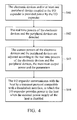
- FIG. 4 illustrates a flowchart of the power management method of the invention suitable for an electronic system 100 having the I/O expander EP and at least one electronic device.
- FIG.1 illustrates an embodiment of an electronic system for performing a power management process.
- the electronic system 100 includes an input/output expander EP (I/O expander), devices M1 ⁇ M5 and a control module CM.
- the control module CM is disposed in the I/O expander EP.
- the control module CM is disposed in one of the electronic devices M1 ⁇ M5, or a host 120 coupled to the electronic system 100, but is not limited thereto.
- the electronic devices M1 ⁇ M5 are overlapped in a direction from the I/O expander EP, and the electronic devices M1 ⁇ M5 and the I/O expander EP have high speed transmission interfaces, e.g., a thunderbolt interface (or light peak interface), such that the electronic devices M1 ⁇ M5 and the I/O expander EP use a transport protocol compatible with a thunderbolt interface to communicate with a host 120.
- the electronic devices M1 ⁇ M5 are coupled in a daisy-chain configuration. Note that amounts and kinds of the electronic devices (e.g., electronic devices M1 ⁇ M5) are not limited thereto.
- the high speed transmission interfaces can be thunderbolt interfaces, but is not limited thereto.
- any electronic device having high speed transmission interfaces can serve as the I/O expander EP or any of the electronic devices M1 ⁇ M5.
- the I/O expander EP is powered by a power supply PS1, and the I/O expander EP outputs power provided by the power supply PS1 to the electronic devices M1 ⁇ M5 or the peripheral devices.
- the host 120 is powered by an external power supply SP2 or a battery disposed in the host 120.
- FIG.2 illustrates an embodiment of an electronic system for performing a power management process.
- the I/O expander EP has an input terminal I1 and output terminals P1 ⁇ P5.
- the input terminal I1 is coupled to the power supply PS1 to receive power from the power supply PS1.
- the I/O expander EP provides power to the peripheral devices through the output terminals P1 ⁇ P4, in which the peripheral devices have no thunderbolt interfaces.
- the output terminals P1 and P2 are universal serial bus (USB) interfaces.
- the output terminal P3 is a high definition multimedia interface (HDMI).
- HDMI high definition multimedia interface
- the output terminal P4 is an internet interface. Note that amounts and kinds of the output terminals are provided for illustration, but are not limited thereto.
- the switching units SW1A and SW1B can selectively enable the host 120 and/or the I/O expander to (or not to) provide power to the output terminal P1.
- Features of the switching units SW2A ⁇ SW4A and SW2B ⁇ SW4B are the same as the features of the switching units SW1A and SW1B, therefore, the details of the switching units SW2A ⁇ SW4A and SW2B ⁇ SW4B are omitted for brevity.
- the I/O expander EP provides power to the electronic devices M1 ⁇ M5 through the output terminal P5.
- Each of the electronic devices M1 ⁇ M5 has the corresponding input terminal for receiving power from the I/O expander EP.
- the power detectors S1 ⁇ S9 detect the real time powers of the peripheral devices and the electronic devices M1 ⁇ M5.
- the switching unit SW5 can selectively provide (or stop providing) power to the I/O expander EP.
- the switching units SW6, SW8 ⁇ SW12 can selectively provide (or stop providing) power to the electronic devices M1 ⁇ M5.
- the control module CM adjusts the current power of the electronic devices and the peripheral devices according to the real time power of the electronic devices (e.g., the electronic devices M1 ⁇ M5) and the peripheral devices, the maximum output power and the parameters, to prevent the power outputted by the I/O expander EP from being larger than the maximum output power.
- the control module CM can detect the maximum power and the minimum power of the electronic device M5 and the kind of the electronic device M5, and adjust the current powers of the electronic devices M1 ⁇ M4 according to the real time power of the electronic devices M1 ⁇ M4 and the peripheral devices and the maximum output power (e.g., 100 Watt) and the parameters, to prevent power outputted by the I/O expander EP from being larger than the maximum output power (e.g., 100 Watt).
- the parameters include the priority order for stopping the provision of power to the electronic devices, utility rates of all of the electronic devices (e.g., electronic devices M1 ⁇ M5) and the maximum powers and the minimum powers of all of the electronic devices (e.g., electronic devices M1 ⁇ M5) and all of peripheral devices.
- the electronic system 100 selectively stops providing power or underclocks the electronic devices M1 ⁇ M5 or the peripheral devices, to prevent power outputted by the I/O expander EP from being larger than the maximum output power.
- the control module CM detects that the minimum power of the electronic device M5 is 10 Watt. Assume that the total current power of the electronic devices M1 ⁇ M4 and the peripheral devices is 95 Watt. If the electronic device M5 joins the electronic system 100, the electronic devices M1 ⁇ M4 or the peripheral devices will operate abnormally.
- the control module CM can stop providing power to the electronic device M1 according to the priority order (e.g., The control module CM has a priority to stop providing power to the electronic device M1), such that the electronic device M5 and other electronic devices operate normally.
- control module CM can selectively turn off any electronic device according to the utility rates of the electronic devices M1 ⁇ M4 and the peripheral device. For example, assume that the electronic device M2 always operates in a stand-by mode. When the electronic device M5 is connected to the electronic device M4, the control module CM stops providing power to the electronic device M2, such that the electronic devices M1, M3-M5 and the peripheral devices can operate normally.
- the control module CM can selectively stop providing power to any device according to the maximum powers or the minimum powers of the electronic devices M1 ⁇ M4 and the peripheral devices. For example, assume that the electronic device M3 has the largest minimum power in the electronic devices M1 ⁇ M4. The electronic system 100 will reduce a lot of power consumption if the control module CM stops providing power to the electronic device M3. Therefore, when the electronic device M5 is connected to the electronic device M4, the control module CM stops providing power to the electronic device M3, such that the electronic devices M1 ⁇ M2 and M4 ⁇ M5 and the peripheral devices can operate normally.
- the control module CM can reduce performance of at least one of the electronic devices M1 ⁇ M4.
- the electronic devices M2, M3 and M4 can respectively be an optical disk drive, a hard disk driver (HDD) and a graphics card, in which the graphics card has a graphics processing unit (GPU) device.
- the control module CM can reduce the read speed of the electronic device M2 and/or the rotational speed of the electronic device M3 and/or the operating frequency of the electronic device M4 to reduce the power consumption of the electronic devices M2, M3 or M4, thereby allowing the electronic device M5 to operate normally.
- control module determines which performances of graphics processing units of the host 120 and the electronic device M4 is the highest and decides to turn off that having the highest performance.
- the graphics processing units of the host 120 and the electronic device M4 can operate at the same time. For example, the graphics processing unit of the host 120 displays the odd frames and the graphics processing unit of the electronic device M4 displays the even frames, but is not limited thereto.
- FIG. 3 illustrates an embodiment of the thunderbolt interface of the invention, in which the thunderbolt interface TB is disposed in the host 120.
- the output terminal P7 of the thunderbolt interface TB is coupled to the output terminal P6 of the I/O expander EP, and the output terminal P9 of the thunderbolt interface TB receives power from the host 120 to provide power to the electronic devices M1 ⁇ M5, the peripheral devices and the I/O expander EP.
- the thunderbolt interface TB stops providing power to the electronic devices M1 ⁇ M5, the peripheral device and the I/O expander EP by the switching unit SW13.
- the thunderbolt interface TB when the power supply PS1 provides power to the I/O expander EP, the thunderbolt interface TB provides power to the electronic devices M1 ⁇ M5 at the same time.
- the power supply PS1 provides power (e.g., 100 Watt) to the I/O expander EP
- the thunderbolt interface TB provides power (e.g., 10 Watt) to the I/O expander EP. Therefore, the I/O expander EP can provide power (e.g., 110 Watt) to the electronic devices M1 ⁇ M5 or the peripheral devices.
- the maximum output power of the I/O expander EP becomes 110 Watt.
- the I/O expander EP when an external power supply PS2 is disabled, provides power (e.g., 10 Watt) to the host 120 by the switching unit SW14 of the thunderbolt interface TB and switching unit SW7, such that the output terminal P8 outputs power to the host 120, thereby allowing the battery of the host 120 to be charged.
- power e.g. 10 Watt
- the host 120 may be other devices, including handheld devices, portable devices, personal digital assistant, multiprocessor-based, microprocessor-based or programmable consumer electronics, network PCs, minicomputers, mainframe computers, and the like, but is not limited thereto.
- the control module CM can be disposed in a single central-processing unit (CPU) or a parallel processing unit associated with a parallel processing environment to perform power management process.
- FIG. 4 illustrates a flowchart of the power management method of the invention suitable for an electronic system 100 having the I/O expander EP and at least one electronic device (e.g., the electronic devices M1 ⁇ M5), in which the electronic devices M1 ⁇ M5 are connected to the I/O expander EP in a daisy-chain configuration.
- the power management method includes the following steps.
- step S41 the electronic devices M1 ⁇ M5 and/or at least one peripheral device coupled to the I/O expander EP is provided power by the I/O expander EP.
- step S42 the real time powers of the electronic devices M1 ⁇ M5 and the peripheral devices are detected, in which the I/O expander EP uses a transport protocol compatible with a thunderbolt interface to communicate with the electronic devices M1 ⁇ M5.
- step S43 the current powers of the electronic devices M1 ⁇ M5 and the peripheral devices are adjusted according to the real time powers of the electronic devices M1 ⁇ M5 and the peripheral devices, the maximum output power and the parameters, to prevent the power outputted by the I/O expander EP from being larger than the maximum output power.
- step S44 the I/O expander EP communicates with the host 120 by a transport protocol compatible with a thunderbolt interface, in which the I/O expander EP provides power to the host 120 when the external power supply PS2 of the host 120 is disabled.
- the maximum output power is the maximum power outputted by the I/O expander EP.
- the maximum output power of the I/O expander EP is 10 Watt.
- the power supply PS1 provides power (e.g., 100 Watt) to the I/O expander EP
- the maximum output power of the I/O expander EP is 100 Watt.
- the host 120 and the power supply PS1 both provide power to the I/O expander EP
- the maximum output power of the I/O expander EP is 110 Watt.
- the magnitudes of powers (10 Watt and 100 Watt) outputted by the host 120 and the power supply PS1 are provided for illustration, but are not limited thereto.
- the electronic system 100 and the power management method of the invention can adjust the current power of the electronic devices and the peripheral devices according to the real time power of the electronic devices and the peripheral devices, the maximum output power and the parameters, thereby preventing the power outputted by the I/O expander EP from being larger than the maximum output power when another electronic device is connected to the electronic system 100, in order to increase the stability of the electronic system.
Landscapes
- Engineering & Computer Science (AREA)
- Theoretical Computer Science (AREA)
- General Engineering & Computer Science (AREA)
- Physics & Mathematics (AREA)
- General Physics & Mathematics (AREA)
- Computer Hardware Design (AREA)
- Power Sources (AREA)
Abstract
Description
- This Application claims priority of Taiwan Patent Application No.
100131879, filed on Sep. 05, 2011 - The present invention relates to electronic systems, and in particular relates to electronic systems having thunderbolt interfaces.
- Recently, computers and networks have made many innovative functions more effective. New peripheral devices, such as internet units and external storage units, can easily be connected to computers or notebooks. However, the management of performance (power) and temperature of the peripheral devices is not effective. Thus, there is a need for an electronic system and a power management method thereof to increase the stability of hosts and peripheral devices and decrease the power consumption of the peripheral devices.
- In light of the previously described problems, the invention provides an electronic device, including an input output expander, at least one electronic device and a control module. The input output expander outputs a power source to a peripheral device by at least one output terminal. The electronic device is coupled to the input output expander in a daisy chain configuration. The control module adjusts current powers of the electronic device and the peripheral device according to real time powers of the electronic device and the peripheral device, a maximum output power and parameters, thereby preventing power outputted by the input output expander from being larger than the maximum output power.
- The invention also provides a power management method suitable for electronic devices connected in a daisy-chain configuration. The power management method includes the steps of: detecting real time powers of the electronic device and the peripheral device; and adjusting current powers of the electronic device and the peripheral device according to the real time powers of the electronic device and the peripheral device, a maximum output power and parameters, thereby preventing power outputted by the input output expander from being larger than the maximum output power.
- A detailed description is given in the following embodiments with reference to the accompanying drawings.
- The present invention can be more fully understood by reading the subsequent detailed description and examples with references made to the accompanying drawings, wherein:
-
FIG.1 illustrates an embodiment of an electronic system for performing a power management process; -
FIG.2 illustrates an embodiment of an electronic system for performing a power management process; -
FIG. 3 illustrates an embodiment of the thunderbolt interface of the invention, in which the thunderbolt interface TB is disposed in thehost 120; and -
FIG. 4 illustrates a flowchart of the power management method of the invention suitable for an electronic system 100 having the I/O expander EP and at least one electronic device. -
FIG.1 illustrates an embodiment of an electronic system for performing a power management process. As shown inFIG. 1 , the electronic system 100 includes an input/output expander EP (I/O expander), devices M1∼M5 and a control module CM. In the embodiment, the control module CM is disposed in the I/O expander EP. In some embodiments, the control module CM is disposed in one of the electronic devices M1∼M5, or ahost 120 coupled to the electronic system 100, but is not limited thereto. The electronic devices M1∼M5 are overlapped in a direction from the I/O expander EP, and the electronic devices M1∼M5 and the I/O expander EP have high speed transmission interfaces, e.g., a thunderbolt interface (or light peak interface), such that the electronic devices M1∼M5 and the I/O expander EP use a transport protocol compatible with a thunderbolt interface to communicate with ahost 120. The electronic devices M1∼M5 are coupled in a daisy-chain configuration. Note that amounts and kinds of the electronic devices (e.g., electronic devices M1∼M5) are not limited thereto. In the embodiments, the high speed transmission interfaces can be thunderbolt interfaces, but is not limited thereto. In other words, any electronic device having high speed transmission interfaces (e.g., more than 5Gbps) can serve as the I/O expander EP or any of the electronic devices M1∼M5. The I/O expander EP is powered by a power supply PS1, and the I/O expander EP outputs power provided by the power supply PS1 to the electronic devices M1∼M5 or the peripheral devices. Thehost 120 is powered by an external power supply SP2 or a battery disposed in thehost 120. -
FIG.2 illustrates an embodiment of an electronic system for performing a power management process. As shown inFIG. 2 , the I/O expander EP has an input terminal I1 and output terminals P1∼P5. In detail, the input terminal I1 is coupled to the power supply PS1 to receive power from the power supply PS1. The I/O expander EP provides power to the peripheral devices through the output terminals P1∼P4, in which the peripheral devices have no thunderbolt interfaces. For example, the output terminals P1 and P2 are universal serial bus (USB) interfaces. The output terminal P3 is a high definition multimedia interface (HDMI). The output terminal P4 is an internet interface. Note that amounts and kinds of the output terminals are provided for illustration, but are not limited thereto. The switching units SW1A and SW1B can selectively enable thehost 120 and/or the I/O expander to (or not to) provide power to the output terminal P1. Features of the switching units SW2A∼SW4A and SW2B∼SW4B are the same as the features of the switching units SW1A and SW1B, therefore, the details of the switching units SW2A∼SW4A and SW2B∼SW4B are omitted for brevity. The I/O expander EP provides power to the electronic devices M1∼M5 through the output terminal P5. Each of the electronic devices M1∼M5 has the corresponding input terminal for receiving power from the I/O expander EP. - The power detectors S1∼S9 detect the real time powers of the peripheral devices and the electronic devices M1∼M5. The switching unit SW5 can selectively provide (or stop providing) power to the I/O expander EP. The switching units SW6, SW8∼SW12 can selectively provide (or stop providing) power to the electronic devices M1∼M5. When a new electronic device is connected to the last sorted electronic device, the control module CM adjusts the current power of the electronic devices and the peripheral devices according to the real time power of the electronic devices (e.g., the electronic devices M1∼M5) and the peripheral devices, the maximum output power and the parameters, to prevent the power outputted by the I/O expander EP from being larger than the maximum output power.
- For example, assume that the maximum power provided to the I/O expander EP by the power supply PS1 is 100 Watt. Therefore, the maximum output power of the I/O expander EP approximates to the 100 Watt (hereinafter the maximum output power is 100 Watt). When the electronic device M5 is connected to the electronic device M4, the control module CM can detect the maximum power and the minimum power of the electronic device M5 and the kind of the electronic device M5, and adjust the current powers of the electronic devices M1∼M4 according to the real time power of the electronic devices M1∼M4 and the peripheral devices and the maximum output power (e.g., 100 Watt) and the parameters, to prevent power outputted by the I/O expander EP from being larger than the maximum output power (e.g., 100 Watt).
- In the embodiment, the parameters include the priority order for stopping the provision of power to the electronic devices, utility rates of all of the electronic devices (e.g., electronic devices M1∼M5) and the maximum powers and the minimum powers of all of the electronic devices (e.g., electronic devices M1∼M5) and all of peripheral devices. The electronic system 100 selectively stops providing power or underclocks the electronic devices M1∼M5 or the peripheral devices, to prevent power outputted by the I/O expander EP from being larger than the maximum output power.
- For example, when the electronic device M5 is connected to the electronic device M4, the control module CM detects that the minimum power of the electronic device M5 is 10 Watt. Assume that the total current power of the electronic devices M1∼M4 and the peripheral devices is 95 Watt. If the electronic device M5 joins the electronic system 100, the electronic devices M1∼M4 or the peripheral devices will operate abnormally. The control module CM can stop providing power to the electronic device M1 according to the priority order (e.g., The control module CM has a priority to stop providing power to the electronic device M1), such that the electronic device M5 and other electronic devices operate normally.
- In the embodiment, the control module CM can selectively turn off any electronic device according to the utility rates of the electronic devices M1∼M4 and the peripheral device. For example, assume that the electronic device M2 always operates in a stand-by mode. When the electronic device M5 is connected to the electronic device M4, the control module CM stops providing power to the electronic device M2, such that the electronic devices M1, M3-M5 and the peripheral devices can operate normally.
- In the embodiment, the control module CM can selectively stop providing power to any device according to the maximum powers or the minimum powers of the electronic devices M1∼M4 and the peripheral devices. For example, assume that the electronic device M3 has the largest minimum power in the electronic devices M1∼M4. The electronic system 100 will reduce a lot of power consumption if the control module CM stops providing power to the electronic device M3. Therefore, when the electronic device M5 is connected to the electronic device M4, the control module CM stops providing power to the electronic device M3, such that the electronic devices M1∼M2 and M4∼M5 and the peripheral devices can operate normally.
- In some embodiments, when the electronic device M5 is connected to the electronic device M4, the control module CM can reduce performance of at least one of the electronic devices M1∼M4. For example, the electronic devices M2, M3 and M4 can respectively be an optical disk drive, a hard disk driver (HDD) and a graphics card, in which the graphics card has a graphics processing unit (GPU) device. The control module CM can reduce the read speed of the electronic device M2 and/or the rotational speed of the electronic device M3 and/or the operating frequency of the electronic device M4 to reduce the power consumption of the electronic devices M2, M3 or M4, thereby allowing the electronic device M5 to operate normally.
- In some embodiments, the control module determines which performances of graphics processing units of the
host 120 and the electronic device M4 is the highest and decides to turn off that having the highest performance. In addition, the graphics processing units of thehost 120 and the electronic device M4 can operate at the same time. For example, the graphics processing unit of thehost 120 displays the odd frames and the graphics processing unit of the electronic device M4 displays the even frames, but is not limited thereto. -
FIG. 3 illustrates an embodiment of the thunderbolt interface of the invention, in which the thunderbolt interface TB is disposed in thehost 120. As shown inFIG. 3 , the output terminal P7 of the thunderbolt interface TB is coupled to the output terminal P6 of the I/O expander EP, and the output terminal P9 of the thunderbolt interface TB receives power from thehost 120 to provide power to the electronic devices M1∼M5, the peripheral devices and the I/O expander EP. In the embodiments, when the power supply PS1 provides power to the I/O expander EP, the thunderbolt interface TB stops providing power to the electronic devices M1∼M5, the peripheral device and the I/O expander EP by the switching unit SW13. In some embodiments, when the power supply PS1 provides power to the I/O expander EP, the thunderbolt interface TB provides power to the electronic devices M1∼M5 at the same time. For example, the power supply PS1 provides power (e.g., 100 Watt) to the I/O expander EP, and the thunderbolt interface TB provides power (e.g., 10 Watt) to the I/O expander EP. Therefore, the I/O expander EP can provide power (e.g., 110 Watt) to the electronic devices M1∼M5 or the peripheral devices. Thus, the maximum output power of the I/O expander EP becomes 110 Watt. In some embodiments, when an external power supply PS2 is disabled, the I/O expander EP provides power (e.g., 10 Watt) to thehost 120 by the switching unit SW14 of the thunderbolt interface TB and switching unit SW7, such that the output terminal P8 outputs power to thehost 120, thereby allowing the battery of thehost 120 to be charged. - In the embodiment, note that the
host 120 may be other devices, including handheld devices, portable devices, personal digital assistant, multiprocessor-based, microprocessor-based or programmable consumer electronics, network PCs, minicomputers, mainframe computers, and the like, but is not limited thereto. The control module CM can be disposed in a single central-processing unit (CPU) or a parallel processing unit associated with a parallel processing environment to perform power management process. -
FIG. 4 illustrates a flowchart of the power management method of the invention suitable for an electronic system 100 having the I/O expander EP and at least one electronic device (e.g., the electronic devices M1∼M5), in which the electronic devices M1∼M5 are connected to the I/O expander EP in a daisy-chain configuration. As shown inFIG. 4 , the power management method includes the following steps. - In step S41, the electronic devices M1∼M5 and/or at least one peripheral device coupled to the I/O expander EP is provided power by the I/O expander EP. In step S42, the real time powers of the electronic devices M1∼M5 and the peripheral devices are detected, in which the I/O expander EP uses a transport protocol compatible with a thunderbolt interface to communicate with the electronic devices M1∼M5. In step S43, the current powers of the electronic devices M1∼M5 and the peripheral devices are adjusted according to the real time powers of the electronic devices M1∼M5 and the peripheral devices, the maximum output power and the parameters, to prevent the power outputted by the I/O expander EP from being larger than the maximum output power. In step S44, the I/O expander EP communicates with the
host 120 by a transport protocol compatible with a thunderbolt interface, in which the I/O expander EP provides power to thehost 120 when the external power supply PS2 of thehost 120 is disabled. - In detail, the maximum output power is the maximum power outputted by the I/O expander EP. For example, when only the
host 120 provides power (e.g., 10 Watt) to the I/O expander EP, the maximum output power of the I/O expander EP is 10 Watt. When only the power supply PS1 provides power (e.g., 100 Watt) to the I/O expander EP, the maximum output power of the I/O expander EP is 100 Watt. When thehost 120 and the power supply PS1 both provide power to the I/O expander EP, the maximum output power of the I/O expander EP is 110 Watt. The magnitudes of powers (10 Watt and 100 Watt) outputted by thehost 120 and the power supply PS1 are provided for illustration, but are not limited thereto. - The electronic system 100 and the power management method of the invention can adjust the current power of the electronic devices and the peripheral devices according to the real time power of the electronic devices and the peripheral devices, the maximum output power and the parameters, thereby preventing the power outputted by the I/O expander EP from being larger than the maximum output power when another electronic device is connected to the electronic system 100, in order to increase the stability of the electronic system.
- The foregoing has outlined features of several embodiments so that those skilled in the art may better understand the detailed description that follows. Those skilled in the art should appreciate that they may readily use the present disclosure as a basis for designing or modifying other processes and structures for carrying out the same purposes and/or achieving the same advantages of the embodiments introduced herein. Those skilled in the art should also realize that such equivalent constructions do not depart from the spirit and scope of the present disclosure, and that they may make various changes, substitutions and alterations herein without departing from the spirit and scope of the present disclosure.
Claims (15)
- An electronic system, comprising:an input output expander, outputting a power source to a peripheral device by at least one output terminal;at least one electronic device, coupled to the input output expander in a daisy chain configuration; anda control module, adjusting current powers of the electronic device and the peripheral device according to real time powers of the electronic device and the peripheral device, a maximum output power and parameters, thereby preventing power outputted by the input output expander from being larger than the maximum output power.
- The electronic system as claimed in claim 1, wherein the parameters comprise a priority order, such that the control module selectively stops providing power to or underclocks the electronic device or the peripheral device according to the priority order, thereby preventing power outputted by the input output expander from being larger than the maximum output power.
- The electronic system as claimed in claim 1, wherein the parameters comprise utility rates of the electronic device and the peripheral device, such that the control module selectively stops providing power to or underclocks the electronic device or the peripheral device according to the utility rates, thereby preventing power outputted by the input output expander from being larger than the maximum output power.
- The electronic system as claimed in claim 1, wherein the parameters comprise maximum powers and minimum powers of the electronic device and the peripheral device, such that the control module selectively stops providing power to or underclocks the electronic device or the peripheral device according to the maximum powers and the minimum powers, thereby preventing power outputted by the input output expander from being larger than the maximum output power.
- The electronic system as claimed in claim 1, wherein the input output expander communicates with a host by a transport protocol compatible with a thunderbolt interface and the input output expander provides power to the host when an external power supply of the host is disabled.
- The electronic system as claimed in claim 1, wherein the control module is disposed in the electronic device, the input output expander or the host.
- The electronic system as claimed in claim 1, wherein each of the input output expander and the electronic device includes at least one power detector to detect the real time powers.
- The electronic system as claimed in claim 1, wherein the electronic device is overlapped in a direction from the input output expander and uses a transport protocol compatible with a thunderbolt interface to communicate with the host.
- A power management method, suitable for an electronic system having at least one electronic device and an input output expander connected in a daisy-chain configuration to the electronic device and coupled to at least one peripheral device, comprising:detecting real time powers of the electronic device and the peripheral device; andadjusting current powers of the electronic device and the peripheral device according to the real time powers of the electronic device and the peripheral device, a maximum output power and parameters, thereby preventing power outputted by the input output expander from being larger than the maximum output power.
- The power management method as claimed in claim 9, further comprising: providing power to the electronic device and/or the peripheral device by the input output expander.
- The power management method as claimed in claim 9, further comprising: communicating between the input output expander and a host by a transport protocol compatible with a thunderbolt interface, wherein the input output expander provides power to the host when an external power supply of the host is disabled.
- The power management method as claimed in claim 9, wherein the parameters comprise a priority order of the electronic devices, such that the control module selectively stops providing power to or underclocks the electronic device or the peripheral device according to the priority order, thereby preventing power outputted by the input output expander from being larger than the maximum output power.
- The power management method as claimed in claim 9, wherein the parameters comprise utility rates of the electronic device and the peripheral device, such that the control module selectively stops providing power to or underclocks the electronic device or the peripheral device according to the utility rates, thereby preventing power outputted by the input output expander from being larger than the maximum output power.
- The power management method as claimed in claim 9, wherein the parameters comprise the maximum powers and the minimum powers of the electronic device and the peripheral device, such that the control module selectively stops providing power to or underclocks the electronic device or the peripheral device according to the maximum powers and the minimum powers, thereby preventing power outputted by the input output expander from being larger than the maximum output power.
- The power management method as claimed in claim 9, wherein the control module is disposed in the electronic device, the input output expander or the host and the electronic device uses a transport protocol compatible with a thunderbolt interface to communicate with the host.
Applications Claiming Priority (1)
| Application Number | Priority Date | Filing Date | Title |
|---|---|---|---|
| TW100131879A TWI590065B (en) | 2011-09-05 | 2011-09-05 | Electronic system and power management method |
Publications (1)
| Publication Number | Publication Date |
|---|---|
| EP2565750A1 true EP2565750A1 (en) | 2013-03-06 |
Family
ID=47008291
Family Applications (1)
| Application Number | Title | Priority Date | Filing Date |
|---|---|---|---|
| EP12182882A Withdrawn EP2565750A1 (en) | 2011-09-05 | 2012-09-04 | Electronic systems and power management methods thereof |
Country Status (3)
| Country | Link |
|---|---|
| US (1) | US9170623B2 (en) |
| EP (1) | EP2565750A1 (en) |
| TW (1) | TWI590065B (en) |
Families Citing this family (6)
| Publication number | Priority date | Publication date | Assignee | Title |
|---|---|---|---|---|
| TW201317791A (en) * | 2011-10-17 | 2013-05-01 | Acer Inc | Electronic devices and electronic systems |
| CN107025195A (en) * | 2016-01-30 | 2017-08-08 | 鸿富锦精密电子(重庆)有限公司 | Power supply system of electronic device |
| CN107025192A (en) * | 2016-01-30 | 2017-08-08 | 鸿富锦精密电子(重庆)有限公司 | Electronic installation connects system |
| CN107025191A (en) * | 2016-01-30 | 2017-08-08 | 鸿富锦精密电子(重庆)有限公司 | Electronic installation connects system |
| CN107024966A (en) * | 2016-01-30 | 2017-08-08 | 鸿富锦精密工业(深圳)有限公司 | Electronic installation connects system |
| CN107025194A (en) * | 2016-01-30 | 2017-08-08 | 鸿富锦精密电子(重庆)有限公司 | Power supply system of electronic device |
Citations (7)
| Publication number | Priority date | Publication date | Assignee | Title |
|---|---|---|---|---|
| US6064554A (en) * | 1997-04-26 | 2000-05-16 | Samsung Electronics Co., Ltd. | Overcurrent protection circuit and method for universal serial bus hub unit |
| US20030070103A1 (en) * | 2001-09-15 | 2003-04-10 | Lg Electronics Inc. | Power supply controlling apparatus of a device connected to a serial bus |
| EP1659478A1 (en) * | 2003-08-28 | 2006-05-24 | Fujitsu Limited | Host apparatus, device, and communication system control method |
| US20060259792A1 (en) * | 2005-05-10 | 2006-11-16 | Dove Daniel J | Rapid load reduction for power-over-LAN system |
| US20080168283A1 (en) * | 2007-01-05 | 2008-07-10 | Avaya Technology Llc | Apparatus and methods for managing Power distribution over Ethernet |
| US20090100275A1 (en) * | 2007-10-15 | 2009-04-16 | Ray Chang | Dynamic port power allocation apparatus and methods |
| GB2460450A (en) * | 2008-05-30 | 2009-12-02 | Cmd Ltd | Power control device having communication with primary device |
Family Cites Families (6)
| Publication number | Priority date | Publication date | Assignee | Title |
|---|---|---|---|---|
| CN101441506B (en) | 2007-11-20 | 2011-05-11 | 中兴通讯股份有限公司 | Blade server system and power consumption management method thereof |
| TWI387180B (en) | 2009-01-09 | 2013-02-21 | Pegatron Corp | Power switch circuit of portable electronic device |
| US8261001B2 (en) * | 2009-04-27 | 2012-09-04 | Cisco Technology, Inc. | Network range extender device |
| TWI405084B (en) | 2009-10-22 | 2013-08-11 | Giga Byte Tech Co Ltd | Multimedia system |
| US20110167176A1 (en) | 2010-01-06 | 2011-07-07 | Apple Inc. | Connecting multiple accessories to a portable computing device |
| US9720469B2 (en) * | 2011-10-04 | 2017-08-01 | Veedims, Llc | System and method for auto-discovery and mapping of networked modules |
-
2011
- 2011-09-05 TW TW100131879A patent/TWI590065B/en not_active IP Right Cessation
-
2012
- 2012-09-04 EP EP12182882A patent/EP2565750A1/en not_active Withdrawn
- 2012-09-04 US US13/603,292 patent/US9170623B2/en active Active
Patent Citations (7)
| Publication number | Priority date | Publication date | Assignee | Title |
|---|---|---|---|---|
| US6064554A (en) * | 1997-04-26 | 2000-05-16 | Samsung Electronics Co., Ltd. | Overcurrent protection circuit and method for universal serial bus hub unit |
| US20030070103A1 (en) * | 2001-09-15 | 2003-04-10 | Lg Electronics Inc. | Power supply controlling apparatus of a device connected to a serial bus |
| EP1659478A1 (en) * | 2003-08-28 | 2006-05-24 | Fujitsu Limited | Host apparatus, device, and communication system control method |
| US20060259792A1 (en) * | 2005-05-10 | 2006-11-16 | Dove Daniel J | Rapid load reduction for power-over-LAN system |
| US20080168283A1 (en) * | 2007-01-05 | 2008-07-10 | Avaya Technology Llc | Apparatus and methods for managing Power distribution over Ethernet |
| US20090100275A1 (en) * | 2007-10-15 | 2009-04-16 | Ray Chang | Dynamic port power allocation apparatus and methods |
| GB2460450A (en) * | 2008-05-30 | 2009-12-02 | Cmd Ltd | Power control device having communication with primary device |
Also Published As
| Publication number | Publication date |
|---|---|
| US9170623B2 (en) | 2015-10-27 |
| TW201312363A (en) | 2013-03-16 |
| US20130061067A1 (en) | 2013-03-07 |
| TWI590065B (en) | 2017-07-01 |
Similar Documents
| Publication | Publication Date | Title |
|---|---|---|
| US10797517B2 (en) | System and method for providing wireless power in a removable wireless charging module | |
| US9218031B2 (en) | System and method for providing wireless power feedback in a wireless power delivery system | |
| CN108062286B (en) | universal serial bus hub | |
| US9170623B2 (en) | Electronic systems and power management methods thereof | |
| US9280193B2 (en) | System and method for extending system uptime while running on backup power | |
| US8937497B1 (en) | Power supply monitor | |
| US9729343B2 (en) | Upstream device overvoltage detection with deactivation of downstream device power | |
| US8941361B2 (en) | Computer system and control method thereof | |
| US8578198B2 (en) | Controlling power received through multiple bus interfaces in a portable computing device | |
| US9590793B2 (en) | Apparatus and method for signal aggregation in an information handling system | |
| US8289002B2 (en) | Mother board adapted to rapidly charge handheld multimedia device | |
| KR20150085642A (en) | Power supply, electronic apparatus including the same and method for power supplying | |
| US9804646B2 (en) | Host controlled IO power management | |
| EP2565748A2 (en) | Electronic systems and performance control methods | |
| CN102096457A (en) | Processing device and operating system | |
| US20060107075A1 (en) | Independent control of output current balance between paralleled power units | |
| TW201443622A (en) | Providing power to integrated electronics within a cable | |
| US10627890B2 (en) | Bridge module and operation method thereof | |
| EP2653976A1 (en) | Electronic system with a Mini-DisplayPort | |
| JP2010055421A (en) | Connection device and connection method | |
| US8607087B2 (en) | Host device of dual power supply | |
| CN102999149A (en) | Electronic system and power management method | |
| CN112421760A (en) | Method and device for controlling exciting current of UPS (uninterrupted Power supply) isolation transformer | |
| US9081559B2 (en) | Electronic systems and power management methods thereof | |
| US9703347B2 (en) | Motherboard with backup power and operation system utilizing the same |
Legal Events
| Date | Code | Title | Description |
|---|---|---|---|
| PUAI | Public reference made under article 153(3) epc to a published international application that has entered the european phase |
Free format text: ORIGINAL CODE: 0009012 |
|
| AK | Designated contracting states |
Kind code of ref document: A1 Designated state(s): AL AT BE BG CH CY CZ DE DK EE ES FI FR GB GR HR HU IE IS IT LI LT LU LV MC MK MT NL NO PL PT RO RS SE SI SK SM TR |
|
| AX | Request for extension of the european patent |
Extension state: BA ME |
|
| 17P | Request for examination filed |
Effective date: 20130904 |
|
| RBV | Designated contracting states (corrected) |
Designated state(s): AL AT BE BG CH CY CZ DE DK EE ES FI FR GB GR HR HU IE IS IT LI LT LU LV MC MK MT NL NO PL PT RO RS SE SI SK SM TR |
|
| STAA | Information on the status of an ep patent application or granted ep patent |
Free format text: STATUS: EXAMINATION IS IN PROGRESS |
|
| 17Q | First examination report despatched |
Effective date: 20170717 |
|
| 18D | Application deemed to be withdrawn |
Effective date: 20180130 |