EP2565617A1 - A smear preparation device - Google Patents
A smear preparation device Download PDFInfo
- Publication number
- EP2565617A1 EP2565617A1 EP11179512A EP11179512A EP2565617A1 EP 2565617 A1 EP2565617 A1 EP 2565617A1 EP 11179512 A EP11179512 A EP 11179512A EP 11179512 A EP11179512 A EP 11179512A EP 2565617 A1 EP2565617 A1 EP 2565617A1
- Authority
- EP
- European Patent Office
- Prior art keywords
- lower unit
- unit
- preparation device
- slide
- disposed
- Prior art date
- Legal status (The legal status is an assumption and is not a legal conclusion. Google has not performed a legal analysis and makes no representation as to the accuracy of the status listed.)
- Granted
Links
Images








Classifications
-
- G—PHYSICS
- G01—MEASURING; TESTING
- G01N—INVESTIGATING OR ANALYSING MATERIALS BY DETERMINING THEIR CHEMICAL OR PHYSICAL PROPERTIES
- G01N1/00—Sampling; Preparing specimens for investigation
- G01N1/28—Preparing specimens for investigation including physical details of (bio-)chemical methods covered elsewhere, e.g. G01N33/50, C12Q
- G01N1/2813—Producing thin layers of samples on a substrate, e.g. smearing, spinning-on
-
- B—PERFORMING OPERATIONS; TRANSPORTING
- B01—PHYSICAL OR CHEMICAL PROCESSES OR APPARATUS IN GENERAL
- B01L—CHEMICAL OR PHYSICAL LABORATORY APPARATUS FOR GENERAL USE
- B01L9/00—Supporting devices; Holding devices
- B01L9/52—Supports specially adapted for flat sample carriers, e.g. for plates, slides, chips
-
- B—PERFORMING OPERATIONS; TRANSPORTING
- B01—PHYSICAL OR CHEMICAL PROCESSES OR APPARATUS IN GENERAL
- B01L—CHEMICAL OR PHYSICAL LABORATORY APPARATUS FOR GENERAL USE
- B01L2300/00—Additional constructional details
- B01L2300/08—Geometry, shape and general structure
- B01L2300/0809—Geometry, shape and general structure rectangular shaped
- B01L2300/0822—Slides
Definitions
- the present invention relates to a smear preparation device.
- the present invention relates to a semiautomatic smear preparation device.
- Smear preparation devices are known.
- smear preparation devices are known in which a spreader blade is moved by an operator, for example, from EP 0 047 189 , US 4,516,522 , NL 8503194 and US 6,083,759 .
- a smear preparation device having a spreader 10 is shown in EP 0 047 189 .
- the spreader 10 has two handles 32 which project upwards on both sides of the spreader 10. An operator of the smear preparation device grips the two handles 32 and moves the spreader 10.
- This invention provides a smear preparation device that addresses, amongst other things, this problem.
- a smear preparation device is sought for relatively low volumes.
- the present invention provides a solution to users having a relatively low smear rate for different bodily fluids in a standardised way.
- the smears are prepared manually or with a conventional device, such as the HemaPrep ® manufactured by J.P. Gilbert Co. Boyertown, PA, USA.
- a conventional device such as the HemaPrep ® manufactured by J.P. Gilbert Co. Boyertown, PA, USA.
- the blood volume is not defined and the process of preparing the smear is highly dependent on the individual user and his experiences to smear preparation.
- the company Alpha-scientific Cop. http://www.alpha-scientific.com/ ) offer a single use article which cap pierces an EDTA tube to obtain a defined volume of a single blood drop out without opening the EDTA tube itself. Whilst this single use article offers the possibility to provide a defined volume of blood for the smear preparation and reduce the infection risk for the user, the problem remains of providing a standardised smear from the blood drop.
- the HemaPrep ® suffers from the disadvantage that the system is not easy to clean and cannot be easily disinfected which is undesirable due to the intended use with human and veterinary samples which can be highly infectious.
- the present invention addresses the problems identified above.
- the smear preparation device provides a device which provides smear quality even for users having a low smear rate per day, as well as for laboratories which offer digital morphology technology to hospital wards but are not able to provide smears with a certain quality, in particular, with a consistent, predictable quality.
- a smear preparation device comprising: a lower unit on which a slide is disposable at a receiving location, the lower unit having a first side and a second side; an upper unit movably connectable to the lower unit, and arranged to receive a spreader blade for smearing a sample on the slide, the upper unit comprising: an upper part; and first and second side parts projecting downwards from the upper part and substantially covering the first and second sides of the lower unit.
- the smear preparation device further comprises a first guide rail 30 disposed on at least one of the lower unit 2 and the upper unit 4 and at least one first engaging means 52 disposed on the other of the at least one of the lower unit 2 and the upper unit 4, wherein the first guide rail 30 is engagable with the first engaging means 52 so that the speed with which the lower unit 2 and the upper unit 4 are movable with respect to one another is controlled.
- a smear preparation device comprising: a lower unit on which a slide is disposable at a receiving location; an upper unit movably connectable to the lower unit, and arranged to receive a spreader blade for smearing a sample on the slide, the device further comprising a first guide rail disposed on at least one of the lower unit and the upper unit and at least one first engaging means disposed on the other of the at least one of the lower unit and the upper unit, wherein the first guide rail is engagable with the first engaging means so that the speed with which the lower unit and the upper unit are movable with respect to one another is controlled.
- the control of the smear preparation device is improved, so that the consistency of the smears prepared using the device is improved.
- the control of the speed with which the upper and lower units move with respect to one another is improved.
- the lower unit 2 has a first side 22 and a second side 24, and the upper unit 4 comprises: an upper part 12; and first and second side parts 14, 16 projecting downwards from the upper part 12 and substantially covering the first and second sides 22, 24 of the lower unit 2.
- the first and second sides 22, 24 extend in a lengthwise direction of the device and extend to the extent of a zone, in the lengthwise direction, in which the sample is smeared.
- the upper unit 4 extends over an upper surface 20 of the lower unit 2 and the first and second sides 22, 24 of the lower unit 2 to substantially form a cover over a zone in which the sample is smeared when the device is in an assembled state.
- the smear preparation device further comprises a second guide rail 32 disposed on at least one of the lower unit 2 and the upper unit 4 and at least one second engaging means 50 disposed on the other of the at least one of the lower unit 2 and the upper unit 4, wherein the second guide rail 32 is engagable with the second engaging means 50 to allow the upper unit 4 to be removably connected to the lower unit 2.
- At least one of the first guide rail 30 and the second guide rail 32 is disposed on the upper unit 4 and at least one of the first engaging means 52 and the second engaging means 50 is disposed on the lower unit (4), respectively.
- the first and second engaging portions 52, 50 comprise one or more spring portions 52, 50 which are arranged to engage with at least one of the first and second guide rail 30, 32, respectively.
- the first and second engaging portions 52, 50 in an engaged state exert a force on the first and second guide rails 30, 32, respectively.
- the first engaging portion 52 is adjustable to adjust the force exerted on the first guide rail 30 to control the speed with which the lower unit 2 and the upper unit 4 are movable with respect to one another.
- the upper unit 4 and the lower unit 2 are pivotable with respect to one another to an open position in which a slide 6 can be disposed and removed from the lower unit 2.
- the upper unit 4 and lower unit 2 are pivotable with respect to one another to a closed position in which the smear can be prepared by moving the spreader blade 18 with respect to the slide disposed on the lower unit 2.
- the lower unit 2 comprises a marked area 62, 64 giving an indication to the user of where the sample is to be disposed 62 and the volume of the sample to be disposed 64, wherein the marked area 62, 64 is visible to the user through the slide 6 when the slide 6 is disposed on the lower unit 2.
- the smear preparation device further comprises a spreader blade 18.
- the spring portions 52, 50 comprise at least one clip pin, the clip pin comprising a spring and a cap.
- the force exerted by the one or more spring portions 52, 50 is adjusted by depressing the spring portion 52, 50 into the lower unit 2 or upper unit 4, respectively.
- the cap in the first engaging portion 52, is arranged to extend and retract with respect to the spring to vary the extent to which the spring portion 52 extends into the first guide rail 30, so that the speed with which the upper unit 4 moves with respect to the lower unit 2 is controlled.
- the second engaging portion 50, the cap is arranged to extend and retract with respect to the spring to vary the extent to which the spring portion 50 extends into the second guide rail 32, so that the force required to interconnect the lower unit 2 with respect to the upper unit 4 is controlled.
- the cap when the cap is extended on the spring, it extends into the first guide rail 30 to cause a decrease in the relative speed with which the upper unit 4 moves with respect to the lower unit 2.
- the spring portion when the cap is retracted on the spring, the spring portion extends to a lesser degree into the first guide rail (30) to increase the relative speed with which the upper unit (4) moves with respect to the lower unit (2).
- the upper unit 4 and lower unit 2 are pivotally mounted with respect to one another.
- the upper unit 4 pivots with respect to lower unit 2 around an axis defined by the locations of the engagement of the at least one second engaging portion 50 with the at least one second guide rail 32.
- the force with which the upper unit 4 is held in its pivotable mounted position with respect to the lower unit 2 is determined by the force exerted by the second engaging portion 50 in the second guide rail 32.
- the at least one of the first and second engaging portions is disposed in the lower unit 2, and wherein the lower unit 2 comprises a body portion into which the at least one of the first and second engaging portions 52, 50 extends and exerts a force outwards from the first and second sides 22, 24 of the lower unit 2.
- the upper unit 4 and the lower unit 2 are substantially perpendicular with respect to one another, in particular, are at an angle of 92° with respect to one another.
- the upper unit 4 in an engaging position in which the upper unit 4 is engagable with the lower unit 2 by virtue of the second engaging means 50 and the second guide rail 32, the upper unit 4 is at an angle with respect to the lower unit 2 of approximately 45°, in particular, 42°.
- the smear preparation device further comprises position maintaining portions 42, 44 disposed on an underside of the lower unit 2, to maintain the position of the lower unit 2 with respect to an object on which it is disposed during a smear preparing process.
- the position maintaining portions 42, 44 comprise rubber points.
- an under side of the lower unit 2 is provided with a recess for storing a reserve spreader blade 18.
- first and second guide rails 30, 32 are disposed in the upper unit 4, and wherein the first and second guide rails 30, 32 define first and second longitudinal channel pairs 34, 36, each extending along the longitudinal direction of the first and second side parts 14, 16 to receive the first and second engaging portions 52, 50, respectively.
- the first longitudinal channel pair 34 is disposed beneath the second longitudinal channel pair 36.
- the spreader blade 18 is made of glass, plastic or an other synthetic material, in particular the spreader blade 18 may be made of glass, plastic and the slide 6 may be made of glass.
- the spreader blade 18 is arranged to form a mono layer of sample on the slide 6 when the spreader blade 18 is moved across the slide 6 to smear the sample.
- the spreader blade 18 is removably mounted on the upper unit 4 with a screw mounting means or a magnetic mounting means.
- the spreader blade 18 is mounted at an angle with respect to the slide 6 of 55 to 65°, in particular, at around 60°.
- the slide 6 comprises a smear portion 6a on which the smear is prepared, and an identification portion 6b on which data is provided regarding the slide, and wherein, when the upper unit 4 and the lower unit 2 are in an assembled state, a window 26 is formed through which data on the identification portion 6b is readable.
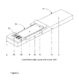
- Figure 1 shows the smear preparation device according to an embodiment of the present invention in its disassembled state.
- the smear preparation device is portable, in particular, it may be pocket sized.
- the smear preparation device is of a semiautomatic type, that is whilst a user is involved in the preparation of the smear, the device is configured such that the result achieved does not depend on the skill or experience of the user. In this way, a compact device is achieved which provides consistent results.
- the smear preparation device provides a smear of a sample.
- the sample is provided in a fluid, in particular liquid form.
- the sample may be a blood sample or other bodily fluids.
- the type of the sample is not limited in this respect and, in principle may be any type of fluid which may be formed into a smear on a slide.
- the device is used to prepare smears of human and veterinary body fluids. It also is possible to prepare smears from cell cultures and antibody titer tests using the device of the present invention.
- the smear preparation device comprises a lower unit 2 on which a slide 6 is disposable at a receiving location.
- the lower unit 2 has a first side 22 and a second side 24.
- the smear preparation device further comprises an upper unit 4 movably connectable to the lower unit 2.
- the upper unit 4 is arranged to receive a spreader blade 18 for smearing a sample on the slide 6.
- the upper unit 4 comprises in the first embodiment an upper part 12. It further comprises first and second side parts 14, 16 projecting downwards from the upper part 12 and substantially covering the first and second sides 22, 24 of the lower unit 2.
- the smear preparation device may also comprise a first guide rail 30 disposed on at least one of the lower unit 2 and the upper unit 4. It may also further comprise at least one first engaging means 52 disposed on the other of the at least one of the lower unit 2 and the upper unit 4, wherein the first guide rail 30 is engagable with the first engaging means 52 so that the speed with which the lower unit 2 and the upper unit 4 are movable with respect to one another is controlled.
- the smear preparation device comprises a lower unit 2 on which a slide 6 is disposable at a receiving location.
- the smear preparation device also comprises an upper unit 4 movably connectable to the lower unit 2.
- the upper unit 4 is arranged to receive a spreader blade 18 for smearing a sample on the slide 6.
- the device further comprises a first guide rail 30 disposed on at least one of the lower unit 2 and the upper unit 4 and at least one first engaging means 52 disposed on the other of the at least one of the lower unit 2 and the upper unit 4, wherein the first guide rail 30 is engagable with the first engaging means 52 so that the speed with which the lower unit 2 and the upper unit 4 are movable with respect to one another is controlled.
- the lower unit 2 may have a first side 22 and a second side 24.
- the upper unit 4 may comprise an upper part 12; and first and second side parts 14, 16 projecting downwards from the upper part 12 and substantially covering the first and second sides 22, 24 of the lower unit 2.
- the lower and upper units 2, 4 extend lengthwise in a longitudinal direction. In an assembled state, the lower and upper units 2, 4 are movable with respect to one another in the longitudinal direction. The smear is prepared by moving the lower and upper units in the longitudinal direction. The speed with which the lower and upper units 2, 4 is controllable. The speed control is described in further detail hereinbelow.
- the lower and upper units 2, 4 are pivotable with respect to one another, which enables them to be connected and disconnected from one another. In an open position, a slide 6 can be disposed in the lower unit 2. In a closed position, the smear can be prepared.
- the interconnection of the lower and upper units 2, 4 is described in further detail hereinbelow.
- the slide 6 is typically a glass slide (also referred to as a slide glass).
- the smear preparation device is arranged to receive one slide at a time.
- the lower unit 2 is arranged to receive one slide at a time.
- the device is may be made from one or more of the following: a high grade or high quality steel or a high grade synthetic material.
- the lower unit 2 has a first side 22 and a second side 24.
- the smear preparation device also comprises an upper unit 4 movably connectable to the lower unit 2.
- the upper unit 4 comprises an upper part 12; and first and second side parts 14, 16.
- the first and second side parts 14, 16 project downwards from the upper part 12 and, in the assembled device, as shown in Figure 2 , cover the first and second sides 22, 24 of the lower unit 2.
- the smear preparation device is arranged to receive a spreader blade 18 for smearing a sample on the slide 6.
- the device includes a spreader blade 18.
- the spreader blade 18 is mountable on the upper unit 4. In particular, it may be removably mounted. It is disposed adjacent to the slide 6 placed on the lower unit 2.
- the spreader blade 18 is arranged with respect to the slide to produce a monolayer of sample on the slide when it is moved across the slide 6 to smear the sample.
- the spreader blade 18 can be made of glass, plastic or other synthetic material.
- the spreader blade may be made e.g. of a material different from that of the slide, in particular, plastic. In this way, it has been found that a particularly controlled quality of smear is produced.
- the slide 6 may comprise a smear portion 6a on which the sample is disposed and subsequently smeared and an identification portion 6b on which data is provided regarding the slide. For example, to identify the slide.
- Figure 2 shows the smear preparation device according to an embodiment of the present invention in its assembled state.
- the first and second side parts 14, 16 of the upper unit 4 are arranged to be gripped by a user.
- the user grips the first and second side parts 14, 16 to move the upper unit 4 with respect to the lower unit 2. This causes the spreader blade 18 to smear the sample on the slide 6.
- the first and second sides 22, 24 extend in a lengthwise direction of the device and extend to the extent of a zone, in the lengthwise direction, in which the sample is smeared.
- the upper unit 4 extends over an upper surface 20 of the lower unit 2 and the first and second sides 22, 24 of the lower unit 2 to substantially form a cover over the zone in which the sample is smeared when in an assembled state.
- the first and second side parts 14, 16 cover the first and second sides 22, 24 of the lower unit 2.
- the user can then grip the first and second side parts 14, 16 to move the upper unit 4 with respect to the lower unit 2. This causes the spreader blade 18 to smear the sample on the slide 6.
- the upper unit 4 extends over an upper surface 20, shown in Figure 1 , of the lower unit 2 and the first and second side parts 14, 16 substantially form a cover over the lower unit 4, at the location where smear portion 6a is located on the lower unit 4.
- the upper and lower units are configured such that in the assembled state the upper unit 4 substantially covers that portion of the lower unit 2 where the smear portion 6a of the slide 6 is located. In this way, the risk that the user touches the sample on the slide is reduced.
- a window 26 is formed through which data on the identification portion 6b is readable.
- the upper and lower units 2, 4 may be configured so that the identification portion of the slide is visible to the user, for example through window 26.
- the window 26 is formed by virtue of the interconnection of the upper and lower units 2, 4.
- the upper and lower units 2, 4 interconnect with each other so as to form the window 26 through which the identification portion 6b of the slide is visible to the user.
- the data on the identification portion 6b is readable by virtue of the window 26.
- the data may be readable by a user or by another means, such as a scanner, for example, a barcode scanner or other automated means.
- the upper unit 4 may be configured so that it only forms a cover on the portion of the lower unit 2 on which the smear portion 6a of the slide 6 is located in use.
- the identification portion 6b of the slide 6 is not covered by the upper unit 4.
- the upper surface 28 of the portion of the lower unit 2 which is arranged to receive the identification portion 6b of the slide is arranged to be flush with the upper surface 20 of the upper unit 4. In this way, a compact device is achieved.
- Figure 3 shows the upper unit of the smear preparation device according to an embodiment of the present invention.
- the upper unit 4 has a first guide rail 30 which, when engaged with first engaging portions 52 (as shown in Figure 4 ) enables the speed with which the upper unit 4 and the lower unit 2 are movable with respect to one another to be controlled.
- the upper unit 4 may also comprise a second guide rail 32, which when engaged with second engaging portions 50 allow the upper unit 4 to be connected to the lower unit 2.
- connection of the upper unit 4 to the lower unit 2 by virtue of the first guide rail 30 provides a controlled relative movement speed between the upper and the lower units 4, 2.
- the manner and mechanism with which the upper unit 4 and lower unit 2 are connected is described in further detail hereinbelow.
- first and second guide rails 30, 32 define first and second longitudinal channel pairs 34, 36, each extending along the longitudinal direction of the first and second side parts 14, 16 of the upper unit 4 to receive at least one first and second engaging portions 52, 50, respectively.
- first and second guide rails 30, 32 are disposed on the upper unit 4 and the first and second engaging means are disposed on the lower unit 2.
- first and second guide rails may be disposed on the lower unit and the first and second engaging portions may be disposed on the upper unit.
- a second guide rail 32 is disposed on the upper unit 4 and at least one second engaging means 50 disposed on the lower unit 2.
- the second guide rail 32 is engagable with the second engaging means 50 to allow the upper unit 4 to be removably connected to the lower unit 2.
- the first and second engaging portions 52, 50 may comprise one or more spring portions 52, 50 which are arranged to engage with at least one of the first and second guide rail 30, 32, respectively.
- the first and second engaging portions 52, 50 exert a force on the first and second guide rails 30, 32, respectively.
- the first engaging portion 52 is adjustable to adjust the force exerted on the first guide rail 30 to control the speed with which the lower unit 2 and the upper unit 4 are movable with respect to one another.
- the spring portions 52, 50 comprise at least one clip pin, the clip pin comprises a spring and a cap.
- the force exerted by the one or more spring portions 52, 50 is adjusted by depressing the spring portion 52, 50 into the lower unit 2 (or upper unit 4, respectively), as shown in and described with reference to Figures 9 and 11 .
- the cap is arranged to extend and retract with respect to the spring to vary the extent to which the spring portion 52 extends into the first guide rail 30. In this way, the speed with which the upper unit 4 moves with respect to the lower unit 2 in the plane in which the slide is disposed in the device can be controlled.
- the cap is arranged to extend and retract with respect to the spring to vary the extent to which the spring portion 50 extends into the second guide rail 32. Similarly, in this way , the force required to interconnect the lower unit 2 with respect to the upper unit 4 can be controlled.
- the first guide rail 30 comprising the first longitudinal channel pair 34 is disposed beneath the second guide rail 32 comprising the second longitudinal channel pair 36.
- Figure 4 shows a side view of the lower unit of the smear preparation device according to an embodiment of the present invention.
- the lower unit 2 has an underside 40.
- the spreader blade 18 is replaceable.
- the underside 40 of the lower unit 2 is provided with a recess 46 for storing a reserve spreader blade. In this way, an efficient use of space is achieved and the user is provided with a spare spreader blade should it be required.
- the lower unit 2 may also comprise a plurality of engaging portions 50, 52, which may typically comprise spring portions 50, 52.
- First and second engaging portions 52, 50 engage with the first and second guide rails 30, 32, respectively.
- the engaging portions 50, 52 are arranged to exert pressure on the upper unit 4 when engaged with the first guide rail 32, and wherein the pressure exerted on the upper unit 4 is adjustable by adjusting the engaging portions, in particular by adjusting the spring portions, to vary the speed with which the upper unit 4 moves with respect to the lower unit 2.
- the underside 40 of the lower unit 2 may further be provided with position maintaining portions 42, 44 for maintaining the position of the device, in particular, the lower unit 2, with respect to the surface on which it is placed.
- the position maintaining portions 42, 44 may comprise, for example, rubber points.
- the position maintaining portions 42, 44 may be disposed towards each corner of the lower unit to provide stability. In this way, the device can be maintained in a stable manner on a working surface.
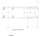
- Figure 5 shows an under side view of the lower unit of the smear preparation device according to an embodiment of the present invention.
- Figure 5 shows in more detail, the underside view shown in Figure 4 .
- the recess 46 in which a reserve spreader blade is disposable is shown.
- the position maintaining means 42, 44 are depicted.
- Two further positioning maintaining means are disposed at the opposite ends of the underside 40 of the lower unit 2. In this way, a stable arrangement is achieved.
- Figure 6a shows the spreader blade of the smear preparation device according to an embodiment of the present invention.
- Figure 6b shows the mounting mechanism for the spreader blade of the smear preparation device according to an embodiment of the present invention.
- the spreader blade is mounted with a screw mounting means.
- the mounting mechanism may also include a magnetic mounting mechanism.
- the spreader blade 18 is mountable on the upper unit 4. In particular, it is disposed adjacent to the slide 6 placed on the lower unit 2.
- the spreader blade 18 is arranged to form a mono layer of sample on the slide 6 when the spreader blade 18 is moved across the slide 6 to smear the sample.
- the spreader blade is mounted at an angle with respect to the slide of 55 to 65°, in particular, at around 60°. In particular, it has been found that the angle at which the spreader blade 18 is mounted with respect to the slide on the lower unit is dependent on the thickness of the blade.
- the spreader blade 18 may be removably mounted on a mounting device.
- the spreader blade is removably mounted on the upper unit 4 with with a mounting means 60, such as screws or a magnetic mounting.
- a mounting means 60 such as screws or a magnetic mounting.
- Figures 7a )-e) show plan views of the lower unit of the smear preparation device according to an embodiment of the present invention.
- Figure 7a shows a plan view of the lower unit 2 without a slide in place.
- the lower unit 2 comprises a receiving section 60 for receiving a slide 6 disposed on the lower unit.
- the receiving section 60 is dimensioned so that when a slide 6 is disposed in the receiving section 60 and the lower unit 2 is engaged with upper unit 4, the slide is received into the second guiding rail 32.
- the receiving section 60 is also known as a frame border.
- the receiving section 60 comprises a recess 60 formed in the lower unit 2.
- the recess 60 is dimensioned to receive the slide 6, wherein when the slide 6 is disposed in the recess 60, an upper surface of the slide 6 is flush with an upper surface 20 of the lower unit 2.
- the lower unit 2 may also be provided with a marked area 62, 64 giving an indication to the user of at least one of where the sample is to be disposed 62 and the volume of the sample to be disposed 64.
- the marked area 62, 64 is visible to the user through the slide 6 when the slide is disposed on the lower unit 2.
- the marked area 62, 64 may also be referred to as an orientation point. The orientation point is indicated to position the sample drop.
- the dimensions of the receiving section 60 are such that they fit for a particular slide, for example but not limited to, a slide from Sysmex.
- the receiving section 60 is dimensioned to accommodate the angle of the particular slide form.
- the orientation point 62, 64 provides information to the user on where to position the sample drop and also an indication of the volume to be provided.
- the orientation point 62 further provides an indication of the maximum extension position from the sample drop to ensure a high quality smear preparation. In this way, a user with even limited experience is able to provide a high quality smear if he follows the indications provided on the device.
- Figure 7b shows a plan view of the lower unit 2 with a slide 6 in place. It is seen that the orientation points 62, 64 are visible to the user through the slide 6.
- Figure 7c shows a plan view of the lower unit 2 with a slide 6 in place wherein a sample drop 70 is disposed on the marked area 64.
- a sample drop 70 is disposed on the marked area 64.
- the user disposes the sample drop as indicated on the marked area a proper smear preparation is achieved.
- Figure 7d shows a plan view of the lower unit 2 if it were visible once the upper unit 4 and the lower unit 2 are connected. The connection of the two units is described in detail below.
- the user grips the first and second side parts 14, 16 of the upper unit 4 and moves the upper unit 4 with respect to the lower unit 2 in the longitudinal direction of the disposition of the slide 6 in the lower unit 2. This causes the spreader blade to move across the slide 6 in the longitudinal direction to prepare the smear.
- Figure 7e shows a plan view of the prepared smear 74.
- Figure 8a shows a side view of the lower part of the smear preparation device according to an embodiment of the present invention. It is seen that the slide 6 disposed in the recess 6 has an upper surface which is flush with an upper surface 20 of the lower unit. Engaging portions 50, 52 are provided in the body of the lower unit 2.
- Figure 8b shows a side view of the upper unit of the smear preparation device according to an embodiment of the present invention.
- Figure 8b shows how the spreader blade 18 is mounted and fixed to the upper unit 4 by using a mounting means 80, such as screws or a magnetic mounting.
- a mounting means 80 such as screws or a magnetic mounting.
- magnetic plug inserts 82 and a magnetic plate 84 which are disposed on an upper portion 18a of the spreader blade 18. In this way, an easy exchange process for the spreader blade is achieved.
- Figure 9 shows an end-on (transverse) cutaway view of the smear preparation device according to an embodiment of the present invention.
- Figure 9 shows the first engaging portion 52.
- the second engaging portion 50 functions in the same manner and is also described herein below.
- Figure 9 shows the upper unit 4 and the lower unit 2 in an assembled state.
- the upper unit 4 and the lower unit 2 are connected by virtue of the engagement of the engaging portions 50, 52 in the guide rails.
- the engaging portions may be spring portions.
- the engaging portion is a clip pin.
- the clip pin 50, 52 comprises a spring 50a, 52b and a cap 50b, 52b.
- the spring 50a, 52a extends into the body of the lower unit 2.
- the cap 50b, 52b extends out of the body and exerts a force on the upper unit 4.
- the cap 50b, 52b is arranged to engage with a guide rail 30, 32 of the upper unit 4.
- the cap 50b, 52b is arranged to extend and retract with respect to the spring 50a, 52a to vary the extent to which the spring portion 50, 52 extends into the guide rails 30, 32, respectively. In this way, the speed with which the upper unit 4 moves with respect to the lower unit 2 is varied. It has been found that the more force the first engaging portion, 52 exerts on the upper unit 4 via, for example, the first guide rail 30, the slower the speed with which the upper unit 4 is moved with respect to the lower unit 2. In particular, when the cap is extended on the spring, it extends into the guide rail to cause a decrease in the relative speed with which the upper unit moves with respect to the lower unit.
- the spring portion 50, 52 is adjusted by depressing the spring portion 50, 52 into the lower unit.
- the clip pin of the second engaging portion 50 By adjusting the clip pin of the second engaging portion 50, the interconnection of the upper and lower units 4, 2 can also be controlled.
- the extension and retraction of the cap is seen and described in further detail in Figures 11a )-d).
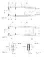
- Figures 10a )-e) show the movement principle of the upper and lower units of the smear preparation device according to an embodiment of the present invention.
- Figure 10a shows the disposition of the lower unit 2 and the upper unit 4 with respect to one another when the slide 6 is disposed on the lower unit 2 and the sample drop is disposed on the slide 6.
- the sample is disposed at marked area 64.
- the user grips the first and second side parts 14, 16 of the upper unit 4 and moves the upper unit 4 in the direction shown by arrow A.
- the upper unit 4 is moved to the location of the sample drop, as shown in Figure 10b ).
- the spreader blade 18 is disposed so that when it reaches the location of the sample drop, the sample drop extends along the length of the blade 18 (see Figure 7d )).
- the sample drop runs along the adjacent edges of the spreader blade 18. This occurs when the upper and lower units are disposed as shown in Figure 10c ).
- the user again by gripping the first and second side walls 14, 16 of the upper unit 4 moves the upper unit 4 in the direction shown by arrow B in Figure 10d ).
- the smear is automatically prepared.
- the user then continues to move the upper unit 4 in the direction shown by arrow C, as shown in Figure 10e ) until it reaches a stop position, which corresponds to the start position shown in Figure 10a ), at which the prepared slide 6 is removed from the lower unit 2.
- the spreading of the sample behind the spreader blade 18 is a visual observation by the user. As soon as the sample is spread over the whole spreader blade the upper unit can slide over the lower unit.
- Figures 11a ) and b) show underside views of the smear preparation device according to an embodiment of the present invention. The features depicted correspond to those described with respect to previously described figures.
- the upper unit 4 and the lower unit 2 are connected by using a guide rail 30.
- the slide 6 also engages with a further guide rail 32 (shown in Figure 3 ).
- the lower unit comprises a body portion into which the engaging portion 50, 52 extends and exerts a force outwards from the first and second sides 22, 24 of the lower unit 2.
- FIG 11a shows engaging portions 52 on either side of the lower unit 2.
- engaging portions 52 engage with the guide rail 30 for, in particular, determining the movement between the lower and upper units 2, 4 in the plane of the slide 6.
- Engaging portions 50 engage with the guide rail for providing a pivotable interconnection between the lower and upper units 2, 4.
- engaging portions 52 extend into the guide rail 30.
- the speed with which the upper unit 4 is moved, in the plane of the slide 6, with respect to the lower unit 2 is controlled.
- the engaging portions 50 do not extend into the guide rail 30 to the extent shown in Figure 11a ).
- the upper unit 4 can be moved faster with respect to the lower unit 2.
- the upper unit 4 will move faster in the guide rail within the upper unit 4 and the speed of the smear preparation is faster, which is for example, desirable when using EDTA blood.
- Figures 11c ) and d) show an engaging portion of the smear preparation device according to an embodiment of the present invention.
- the engaging portion 50, 52 has a spring 52a, 52b and a cap 52b.
- the cap 50b, 52b is disposed on an end of the spring 50a, 50b.
- the cap 50b, 52b is able to move up and down with respect to the spring 50a, 52b, as shown by the arrows D and E in Figures 11c ) and d).
- the cap 50b, 52b is disposed on the spring 50a, 52a and is arranged in use so that it extends into the guide rails.
- the engaging portion 50, 52 is in its extended position.
- the cap 50b, 52b extends on the upper end of the spring 50a, 52a.
- the engaging portion 50, 52 is in its fixed/pressured position, where the cap 50b, 52b is depressed onto the top of the spring 50a, 52b, which allows a higher speed in the guiding rail 30, 32 of the upper unit 4.
- Figures 12a )-c) show the connection principle of the upper unit with respect to the lower unit of the smear preparation device according to an embodiment of the present invention.
- connection of the upper unit 4 to the lower unit 2 is achieved using clip pins based on the principle of a spring support system in the lower unit 2 which are routed by guide rails 30, 32 provided in the upper unit 4 with which they engage.
- These guide rails 30, 32 also allow the upper and lower units 4, 2 to be disconnected from one another.
- the second guide rail 32 allows the upper and lower units 4, 2 to be connected and disconnected with each other, so that they are connectable in a pivotable manner.
- the upper unit 4 and lower unit 2 are pivotally mounted with respect to one another.
- the upper unit 4 pivots with respect to lower unit 2 around an axis defined by two of the spring portions 50.
- the force with which the upper unit 4 is held in its pivotable mounted position with respect to the lower unit 2 is determined by the force exerted by the second engaging portion 50 in the second guide rail 32.
- the upper unit 4 and the lower unit are pivotable with respect to one another to an open position in which a slide can be disposed and removed from the lower unit ( Figure 12b ) and c)).
- the upper unit 4 and lower unit 2 are pivotable with respect to one another to a closed position in which the smear can be prepared by moving the spreader blade with respect to the slide disposed on the lower unit ( Figure 10 ).
- the upper unit 4 and the lower unit 2 are substantially perpendicular with respect to one another, in particular, are at an angle of 92° with respect to one another ( Figure 12b ) and c)).
- the upper unit 4 In an engaging position ( Figure 12a )) in which the upper unit 4 is engagable with the lower unit 2 (by virtue of the second engaging means 50 and the second guide rail 32), the upper unit 4 is at an angle with respect to the lower unit of approximately 45°, in particular, 42°.
- Figure 13 shows a Sysmex slide module for use with the smear preparation device according to an embodiment of the present invention.
- Figure 13 provides the dimensions of the slide.
- the present invention is applicable to other slide types having different dimensions.
- the recess 60 may have different dimensions.
- a major limiting factor determining the size of the compact device of the present invention is the size of the slide itself.
Landscapes
- Chemical & Material Sciences (AREA)
- Health & Medical Sciences (AREA)
- General Health & Medical Sciences (AREA)
- Life Sciences & Earth Sciences (AREA)
- Analytical Chemistry (AREA)
- Biochemistry (AREA)
- Physics & Mathematics (AREA)
- General Physics & Mathematics (AREA)
- Immunology (AREA)
- Pathology (AREA)
- Clinical Laboratory Science (AREA)
- Chemical Kinetics & Catalysis (AREA)
- Sampling And Sample Adjustment (AREA)
Abstract
Description
- The present invention relates to a smear preparation device. In particular, the present invention relates to a semiautomatic smear preparation device.
- Smear preparation devices are known. In particular, smear preparation devices are known in which a spreader blade is moved by an operator, for example, from
EP 0 047 189US 4,516,522 ,NL 8503194 US 6,083,759 . - A smear preparation device having a spreader 10 is shown in
EP 0 047 189handles 32 which project upwards on both sides of the spreader 10. An operator of the smear preparation device grips the twohandles 32 and moves the spreader 10. - However, when the operator moves the spreader 10, there is a risk that operator's fingers may slip from the
handles 32 and touch blood on a slide glass. Similarly, in the devices described inUS 4,516,522 ,NL 8503194 US 6,083,759 , the same risk exists as the device shown inEP 0 047 189 - This invention provides a smear preparation device that addresses, amongst other things, this problem.
- Further, small laboratories do have a certain volume of smears per day, but not a high enough volume to warrant investment into a large smear maker stainer. Therefore, a smear preparation device is sought for relatively low volumes.
- The present invention provides a solution to users having a relatively low smear rate for different bodily fluids in a standardised way.
- Currently, the smears are prepared manually or with a conventional device, such as the HemaPrep® manufactured by J.P. Gilbert Co. Boyertown, PA, USA. With such devices, the blood volume is not defined and the process of preparing the smear is highly dependent on the individual user and his experiences to smear preparation. Thus, it is difficult to prepare smears in a standardised way.
- For blood smears, the company Alpha-scientific Cop. (http://www.alpha-scientific.com/) offer a single use article which cap pierces an EDTA tube to obtain a defined volume of a single blood drop out without opening the EDTA tube itself. Whilst this single use article offers the possibility to provide a defined volume of blood for the smear preparation and reduce the infection risk for the user, the problem remains of providing a standardised smear from the blood drop.
- The HemaPrep® suffers from the disadvantage that the system is not easy to clean and cannot be easily disinfected which is undesirable due to the intended use with human and veterinary samples which can be highly infectious.
- The present invention addresses the problems identified above. The smear preparation device according to the present invention provides a device which provides smear quality even for users having a low smear rate per day, as well as for laboratories which offer digital morphology technology to hospital wards but are not able to provide smears with a certain quality, in particular, with a consistent, predictable quality.
- According to a first aspect of the present invention, there is provided a smear preparation device, comprising: a lower unit on which a slide is disposable at a receiving location, the lower unit having a first side and a second side; an upper unit movably connectable to the lower unit, and arranged to receive a spreader blade for smearing a sample on the slide, the upper unit comprising: an upper part; and first and second side parts projecting downwards from the upper part and substantially covering the first and second sides of the lower unit.
- In this way, the handling is improved and the risk that a user touches the sample is reduced, which thus also improves the overall consistency of smear prepared using the smear preparation device.
- In a second aspect according to the first aspect, the smear preparation device, further comprises a
first guide rail 30 disposed on at least one of thelower unit 2 and theupper unit 4 and at least one first engagingmeans 52 disposed on the other of the at least one of thelower unit 2 and theupper unit 4, wherein thefirst guide rail 30 is engagable with the firstengaging means 52 so that the speed with which thelower unit 2 and theupper unit 4 are movable with respect to one another is controlled. - According to a third aspect of the present invention, there is provided a smear preparation device, comprising: a lower unit on which a slide is disposable at a receiving location; an upper unit movably connectable to the lower unit, and arranged to receive a spreader blade for smearing a sample on the slide, the device further comprising a first guide rail disposed on at least one of the lower unit and the upper unit and at least one first engaging means disposed on the other of the at least one of the lower unit and the upper unit, wherein the first guide rail is engagable with the first engaging means so that the speed with which the lower unit and the upper unit are movable with respect to one another is controlled.
- In this way, the control of the smear preparation device is improved, so that the consistency of the smears prepared using the device is improved. In particular, the control of the speed with which the upper and lower units move with respect to one another is improved.
- In a fourth aspect according to the third aspect, the
lower unit 2 has afirst side 22 and asecond side 24, and theupper unit 4 comprises: anupper part 12; and first andsecond side parts upper part 12 and substantially covering the first andsecond sides lower unit 2. - In a fifth aspect to according to any of the first, second or fourth aspects, the first and
second sides - In a sixth aspect according to any of the first, second, fourth or fifth aspects, the
upper unit 4 extends over anupper surface 20 of thelower unit 2 and the first andsecond sides lower unit 2 to substantially form a cover over a zone in which the sample is smeared when the device is in an assembled state. - In a sixth aspect according to any of the 2nd to 6th aspects, the smear preparation device further comprises a
second guide rail 32 disposed on at least one of thelower unit 2 and theupper unit 4 and at least one second engagingmeans 50 disposed on the other of the at least one of thelower unit 2 and theupper unit 4, wherein thesecond guide rail 32 is engagable with the secondengaging means 50 to allow theupper unit 4 to be removably connected to thelower unit 2. - In an eighth aspect according to any of the 2nd to 7th aspects, at least one of the
first guide rail 30 and thesecond guide rail 32 is disposed on theupper unit 4 and at least one of the firstengaging means 52 and the secondengaging means 50 is disposed on the lower unit (4), respectively. - In a ninth aspect according to any of the 2nd to 8th aspects, the first and second
engaging portions more spring portions second guide rail - In a tenth aspect according to any of the 2nd to 9th aspects, the first and second
engaging portions second guide rails - In an eleventh aspect according to the 10th aspect, the first
engaging portion 52 is adjustable to adjust the force exerted on thefirst guide rail 30 to control the speed with which thelower unit 2 and theupper unit 4 are movable with respect to one another. - In a twelfth aspect according to any of the 1st to 11th aspects, the
upper unit 4 and thelower unit 2 are pivotable with respect to one another to an open position in which aslide 6 can be disposed and removed from thelower unit 2. - In a thirteenth aspect according to any of the 1st to 1th aspects, the
upper unit 4 andlower unit 2 are pivotable with respect to one another to a closed position in which the smear can be prepared by moving thespreader blade 18 with respect to the slide disposed on thelower unit 2. - In a fourteenth aspect according to any of the 1st to 13th aspects, the
lower unit 2 comprises amarked area marked area slide 6 when theslide 6 is disposed on thelower unit 2. - In a fifteenth aspect according to any of the 1st to 14th aspects, the smear preparation device further comprises a
spreader blade 18. - In a sixteenth aspect according to the 9th aspect, the
spring portions - In a seventeenth aspect according to the ninth or 16th aspect, the force exerted by the one or
more spring portions spring portion lower unit 2 orupper unit 4, respectively. - In an eighteenth aspect according to the 16th or 17th aspect, in the first
engaging portion 52, the cap is arranged to extend and retract with respect to the spring to vary the extent to which thespring portion 52 extends into thefirst guide rail 30, so that the speed with which theupper unit 4 moves with respect to thelower unit 2 is controlled. - In a nineteenth aspect according to any of the 6th to 18th aspects, the second
engaging portion 50, the cap is arranged to extend and retract with respect to the spring to vary the extent to which thespring portion 50 extends into thesecond guide rail 32, so that the force required to interconnect thelower unit 2 with respect to theupper unit 4 is controlled. - In a twentieth aspect according to any of the 16th to 18th aspects, when the cap is extended on the spring, it extends into the
first guide rail 30 to cause a decrease in the relative speed with which theupper unit 4 moves with respect to thelower unit 2. - In a 215t aspect according to any of the 16th to 18th or 20th aspects, when the cap is retracted on the spring, the spring portion extends to a lesser degree into the first guide rail (30) to increase the relative speed with which the upper unit (4) moves with respect to the lower unit (2).
- In a 22nd aspect according to any of the preceding aspects, the
upper unit 4 andlower unit 2 are pivotally mounted with respect to one another. - In a 23rd aspect according to the 22nd aspect, the
upper unit 4 pivots with respect tolower unit 2 around an axis defined by the locations of the engagement of the at least onesecond engaging portion 50 with the at least onesecond guide rail 32. - In a 24th aspect according to the 22nd or 23rd aspect, the force with which the
upper unit 4 is held in its pivotable mounted position with respect to thelower unit 2 is determined by the force exerted by the secondengaging portion 50 in thesecond guide rail 32. - In a 25th aspect according to any of the 2nd to 24th aspects, the at least one of the first and second engaging portions is disposed in the
lower unit 2, and wherein thelower unit 2 comprises a body portion into which the at least one of the first and secondengaging portions second sides lower unit 2. - In a 26th aspect according to the 12th or 13th aspect, in the open position, the
upper unit 4 and thelower unit 2 are substantially perpendicular with respect to one another, in particular, are at an angle of 92° with respect to one another. - In a 27th aspect according to any of the preceding aspects, in an engaging position in which the
upper unit 4 is engagable with thelower unit 2 by virtue of the secondengaging means 50 and thesecond guide rail 32, theupper unit 4 is at an angle with respect to thelower unit 2 of approximately 45°, in particular, 42°. - In a 28th aspect according to any of the preceding aspects, the smear preparation device further comprises
position maintaining portions lower unit 2, to maintain the position of thelower unit 2 with respect to an object on which it is disposed during a smear preparing process. - In a 29th aspect according to the 28th aspect, the
position maintaining portions - In a 30th aspect according to the 29th aspect, an under side of the
lower unit 2 is provided with a recess for storing areserve spreader blade 18. - In a 31st aspect according to any of the 2nd to 30th aspect, the first and
second guide rails upper unit 4, and wherein the first andsecond guide rails longitudinal channel pairs second side parts engaging portions - In a 32nd aspect according to the 31st aspect, the first
longitudinal channel pair 34 is disposed beneath the secondlongitudinal channel pair 36. - In a 33rd aspect according to any preceding aspect, the
spreader blade 18 is made of glass, plastic or an other synthetic material, in particular thespreader blade 18 may be made of glass, plastic and theslide 6 may be made of glass. - In a 34th aspect according to any preceding aspect, the
spreader blade 18 is arranged to form a mono layer of sample on theslide 6 when thespreader blade 18 is moved across theslide 6 to smear the sample. - In a 35th aspect according to any preceding aspect, the
spreader blade 18 is removably mounted on theupper unit 4 with a screw mounting means or a magnetic mounting means. - In a 36th aspect according to any preceding aspect, the
spreader blade 18 is mounted at an angle with respect to theslide 6 of 55 to 65°, in particular, at around 60°. - In a 37th aspect according to any preceding aspect, the
slide 6 comprises a smear portion 6a on which the smear is prepared, and an identification portion 6b on which data is provided regarding the slide, and wherein, when theupper unit 4 and thelower unit 2 are in an assembled state, awindow 26 is formed through which data on the identification portion 6b is readable. -
-
Figure 1 shows the smear preparation device according to an embodiment of the present invention in its disassembled state; -
Figure 2 shows the smear preparation device according to an embodiment of the present invention in its assembled state; -
Figure 3 shows the upper unit of the smear preparation device according to an embodiment of the present invention; -
Figure 4 shows a side view of the lower unit of the smear preparation device according to an embodiment of the present invention; -
Figure 5 shows an under side view of the lower unit of the smear preparation device according to an embodiment of the present invention; -
Figure 6a shows the spreader blade of the smear preparation device according to an embodiment of the present invention; -
Figure 6b shows the magnetic mounting for the spreader blade of the smear preparation device according to an embodiment of the present invention; -
Figures 7a )-e) show plan views of the lower part of the smear preparation device according to an embodiment of the present invention; -
Figure 8a shows a side view of the lower part of the smear preparation device according to an embodiment of the present invention; -
Figure 8b shows a side view of the upper part of the smear preparation device according to an embodiment of the present invention; -
Figure 9 shows an end-on view of the smear preparation device according to an embodiment of the present invention; -
Figures 10a )-e) show the movement principle of the upper and lower units of the smear preparation device according to an embodiment of the present invention; -
Figures 11a ) and b) show underneath views of the smear preparation device according to an embodiment of the present invention; -
Figures 11c ) and d) show an engaging portion of the smear preparation device according to an embodiment of the present invention; -
Figures 12a )-c) show the connection principle of the upper unit with respect to the lower unit of the smear preparation device according to an embodiment of the present invention; and -
Figure 13 shows a Sysmex slide module for use with the smear preparation device according to an embodiment of the present invention. - In the detailed description hereinbelow, like reference signs denote like features. The invention is exemplified in the embodiments described below. The invention is not limited to these embodiments, which are schematically shown.
-
Figure 1 shows the smear preparation device according to an embodiment of the present invention in its disassembled state. - According to an embodiment of the present invention, the smear preparation device is portable, in particular, it may be pocket sized. The smear preparation device is of a semiautomatic type, that is whilst a user is involved in the preparation of the smear, the device is configured such that the result achieved does not depend on the skill or experience of the user. In this way, a compact device is achieved which provides consistent results. The smear preparation device provides a smear of a sample. The sample is provided in a fluid, in particular liquid form. The sample may be a blood sample or other bodily fluids. The type of the sample is not limited in this respect and, in principle may be any type of fluid which may be formed into a smear on a slide. Primarily, the device is used to prepare smears of human and veterinary body fluids. It also is possible to prepare smears from cell cultures and antibody titer tests using the device of the present invention.
- According to the first aspect of the present invention, the smear preparation device comprises a
lower unit 2 on which aslide 6 is disposable at a receiving location. Thelower unit 2 has afirst side 22 and asecond side 24. The smear preparation device further comprises anupper unit 4 movably connectable to thelower unit 2. Theupper unit 4 is arranged to receive aspreader blade 18 for smearing a sample on theslide 6. Theupper unit 4 comprises in the first embodiment anupper part 12. It further comprises first andsecond side parts upper part 12 and substantially covering the first andsecond sides lower unit 2. - According to an embodiment of the first aspect of the invention, the smear preparation device may also comprise a
first guide rail 30 disposed on at least one of thelower unit 2 and theupper unit 4. It may also further comprise at least one first engaging means 52 disposed on the other of the at least one of thelower unit 2 and theupper unit 4, wherein thefirst guide rail 30 is engagable with the first engaging means 52 so that the speed with which thelower unit 2 and theupper unit 4 are movable with respect to one another is controlled. These features are optional with respect to the first aspect of the invention. - According to the third aspect of the present invention, the smear preparation device comprises a
lower unit 2 on which aslide 6 is disposable at a receiving location. The smear preparation device also comprises anupper unit 4 movably connectable to thelower unit 2. Theupper unit 4 is arranged to receive aspreader blade 18 for smearing a sample on theslide 6. The device further comprises afirst guide rail 30 disposed on at least one of thelower unit 2 and theupper unit 4 and at least one first engaging means 52 disposed on the other of the at least one of thelower unit 2 and theupper unit 4, wherein thefirst guide rail 30 is engagable with the first engaging means 52 so that the speed with which thelower unit 2 and theupper unit 4 are movable with respect to one another is controlled. - According to an embodiment of the third aspect of the present invention, the
lower unit 2 may have afirst side 22 and asecond side 24. Further, theupper unit 4 may comprise anupper part 12; and first andsecond side parts upper part 12 and substantially covering the first andsecond sides lower unit 2. These features are optional with respect to the first aspect of the invention. - The first and third aspects of the present invention together with various embodiments and further aspects of both the first and third aspects are described hereinbelow in further detail.
- The lower and
upper units upper units upper units - The lower and
upper units slide 6 can be disposed in thelower unit 2. In a closed position, the smear can be prepared. The interconnection of the lower andupper units - The
slide 6 is typically a glass slide (also referred to as a slide glass). In the embodiment shown inFigure 1 , the smear preparation device is arranged to receive one slide at a time. In particular, thelower unit 2 is arranged to receive one slide at a time. - The device is may be made from one or more of the following: a high grade or high quality steel or a high grade synthetic material.
- The
lower unit 2 has afirst side 22 and asecond side 24. The smear preparation device also comprises anupper unit 4 movably connectable to thelower unit 2. Theupper unit 4 comprises anupper part 12; and first andsecond side parts second side parts upper part 12 and, in the assembled device, as shown inFigure 2 , cover the first andsecond sides lower unit 2. - The smear preparation device is arranged to receive a
spreader blade 18 for smearing a sample on theslide 6. In one embodiment, the device includes aspreader blade 18. Thespreader blade 18 is mountable on theupper unit 4. In particular, it may be removably mounted. It is disposed adjacent to theslide 6 placed on thelower unit 2. Thespreader blade 18 is arranged with respect to the slide to produce a monolayer of sample on the slide when it is moved across theslide 6 to smear the sample. Thespreader blade 18 can be made of glass, plastic or other synthetic material. - In one embodiment, where the slide is made of a glass material, the spreader blade may be made e.g. of a material different from that of the slide, in particular, plastic. In this way, it has been found that a particularly controlled quality of smear is produced.
- The
slide 6 may comprise a smear portion 6a on which the sample is disposed and subsequently smeared and an identification portion 6b on which data is provided regarding the slide. For example, to identify the slide. -
Figure 2 shows the smear preparation device according to an embodiment of the present invention in its assembled state. - According to an embodiment, the first and
second side parts upper unit 4 are arranged to be gripped by a user. The user grips the first andsecond side parts upper unit 4 with respect to thelower unit 2. This causes thespreader blade 18 to smear the sample on theslide 6. - The first and
second sides - Further, in one embodiment, the
upper unit 4 extends over anupper surface 20 of thelower unit 2 and the first andsecond sides lower unit 2 to substantially form a cover over the zone in which the sample is smeared when in an assembled state. - In the assembled state, the first and
second side parts second sides lower unit 2. The user can then grip the first andsecond side parts upper unit 4 with respect to thelower unit 2. This causes thespreader blade 18 to smear the sample on theslide 6. - In the assembled state, the
upper unit 4 extends over anupper surface 20, shown inFigure 1 , of thelower unit 2 and the first andsecond side parts lower unit 4, at the location where smear portion 6a is located on thelower unit 4. - The upper and lower units are configured such that in the assembled state the
upper unit 4 substantially covers that portion of thelower unit 2 where the smear portion 6a of theslide 6 is located. In this way, the risk that the user touches the sample on the slide is reduced. - When the
upper unit 4 and thelower unit 2 are in the assembled state, awindow 26 is formed through which data on the identification portion 6b is readable. For example, the upper andlower units window 26. Thewindow 26 is formed by virtue of the interconnection of the upper andlower units lower units window 26 through which the identification portion 6b of the slide is visible to the user. The data on the identification portion 6b is readable by virtue of thewindow 26. The data may be readable by a user or by another means, such as a scanner, for example, a barcode scanner or other automated means. - Indeed the
upper unit 4 may be configured so that it only forms a cover on the portion of thelower unit 2 on which the smear portion 6a of theslide 6 is located in use. As mentioned, the identification portion 6b of theslide 6 is not covered by theupper unit 4. In this way, in the assembled state theupper surface 28 of the portion of thelower unit 2 which is arranged to receive the identification portion 6b of the slide, is arranged to be flush with theupper surface 20 of theupper unit 4. In this way, a compact device is achieved. -
Figure 3 shows the upper unit of the smear preparation device according to an embodiment of the present invention. - In the embodiment shown, the
upper unit 4 has afirst guide rail 30 which, when engaged with first engaging portions 52 (as shown inFigure 4 ) enables the speed with which theupper unit 4 and thelower unit 2 are movable with respect to one another to be controlled. - The
upper unit 4 may also comprise asecond guide rail 32, which when engaged with secondengaging portions 50 allow theupper unit 4 to be connected to thelower unit 2. - The connection of the
upper unit 4 to thelower unit 2 by virtue of thefirst guide rail 30 provides a controlled relative movement speed between the upper and thelower units upper unit 4 andlower unit 2 are connected is described in further detail hereinbelow. - In particular, in one embodiment, the first and
second guide rails second side parts upper unit 4 to receive at least one first and second engagingportions - In the embodiment shown, the first and
second guide rails upper unit 4 and the first and second engaging means are disposed on thelower unit 2. In an alternative embodiment, the first and second guide rails may be disposed on the lower unit and the first and second engaging portions may be disposed on the upper unit. - With reference to
Figures 3 and4 , asecond guide rail 32 is disposed on theupper unit 4 and at least one second engaging means 50 disposed on thelower unit 2. Thesecond guide rail 32 is engagable with the second engaging means 50 to allow theupper unit 4 to be removably connected to thelower unit 2. - with reference to
Figures 4 ,8 ,9 and11 , the first and second engagingportions more spring portions second guide rail portions second guide rails portion 52 is adjustable to adjust the force exerted on thefirst guide rail 30 to control the speed with which thelower unit 2 and theupper unit 4 are movable with respect to one another. As shown inFigures 11c and d , thespring portions - The force exerted by the one or
more spring portions spring portion upper unit 4, respectively), as shown in and described with reference toFigures 9 and11 . - In particular, in the first engaging
portion 52, the cap is arranged to extend and retract with respect to the spring to vary the extent to which thespring portion 52 extends into thefirst guide rail 30. In this way, the speed with which theupper unit 4 moves with respect to thelower unit 2 in the plane in which the slide is disposed in the device can be controlled. - Similarly, in the second engaging
portion 50, the cap is arranged to extend and retract with respect to the spring to vary the extent to which thespring portion 50 extends into thesecond guide rail 32. Similarly, in this way ,the force required to interconnect thelower unit 2 with respect to theupper unit 4 can be controlled. - With reference to
Figures 3 ,9 and11 , when the cap is extended on the spring (refer toFigure 11c ), it extends into the first guide rail 30 (refer toFigure 3 ) to cause a decrease in the relative speed with which theupper unit 4 moves with respect to thelower unit 2. When the cap is retracted on the spring (refer toFigure 11d ), the spring portion extends to a lesser degree into thefirst guide rail 30 to increase the relative speed with which theupper unit 4 moves with respect to thelower unit 2. - In one embodiment, the
first guide rail 30 comprising the firstlongitudinal channel pair 34 is disposed beneath thesecond guide rail 32 comprising the secondlongitudinal channel pair 36. -
Figure 4 shows a side view of the lower unit of the smear preparation device according to an embodiment of the present invention. - The
lower unit 2 has anunderside 40. According to an embodiment of the invention, thespreader blade 18 is replaceable. Theunderside 40 of thelower unit 2 is provided with arecess 46 for storing a reserve spreader blade. In this way, an efficient use of space is achieved and the user is provided with a spare spreader blade should it be required. - The
lower unit 2 may also comprise a plurality of engagingportions spring portions portions second guide rails portions upper unit 4 when engaged with thefirst guide rail 32, and wherein the pressure exerted on theupper unit 4 is adjustable by adjusting the engaging portions, in particular by adjusting the spring portions, to vary the speed with which theupper unit 4 moves with respect to thelower unit 2. - The mechanism of the connection of the upper and
lower units - The
underside 40 of thelower unit 2 may further be provided withposition maintaining portions lower unit 2, with respect to the surface on which it is placed. Theposition maintaining portions position maintaining portions -
Figure 5 shows an under side view of the lower unit of the smear preparation device according to an embodiment of the present invention. In particular,Figure 5 shows in more detail, the underside view shown inFigure 4 . Therecess 46 in which a reserve spreader blade is disposable is shown. Also, the position maintaining means 42, 44 are depicted. Two further positioning maintaining means (not shown) are disposed at the opposite ends of theunderside 40 of thelower unit 2. In this way, a stable arrangement is achieved. -
Figure 6a shows the spreader blade of the smear preparation device according to an embodiment of the present invention.Figure 6b shows the mounting mechanism for the spreader blade of the smear preparation device according to an embodiment of the present invention. InFigure 6b , the spreader blade is mounted with a screw mounting means. The mounting mechanism may also include a magnetic mounting mechanism. - The
spreader blade 18 is mountable on theupper unit 4. In particular, it is disposed adjacent to theslide 6 placed on thelower unit 2. Thespreader blade 18 is arranged to form a mono layer of sample on theslide 6 when thespreader blade 18 is moved across theslide 6 to smear the sample. For example, the spreader blade is mounted at an angle with respect to the slide of 55 to 65°, in particular, at around 60°. In particular, it has been found that the angle at which thespreader blade 18 is mounted with respect to the slide on the lower unit is dependent on the thickness of the blade. - As shown in
Figures 6a and 6b , thespreader blade 18 may be removably mounted on a mounting device. In particular, the spreader blade is removably mounted on theupper unit 4 with with a mounting means 60, such as screws or a magnetic mounting. In this way, a versatile device is provided, in which the blade can be readily replaced if necessary, without requiring any additional tools. - Hereinbelow with respect to the following Figures, it is now described how the smear preparation is carried out and how the
upper unit 4 is connected to thelower unit 2. -
Figures 7a )-e) show plan views of the lower unit of the smear preparation device according to an embodiment of the present invention. -
Figure 7a shows a plan view of thelower unit 2 without a slide in place. Thelower unit 2 comprises a receivingsection 60 for receiving aslide 6 disposed on the lower unit. The receivingsection 60 is dimensioned so that when aslide 6 is disposed in the receivingsection 60 and thelower unit 2 is engaged withupper unit 4, the slide is received into the second guidingrail 32. The receivingsection 60 is also known as a frame border. In particular, the receivingsection 60 comprises arecess 60 formed in thelower unit 2. Therecess 60 is dimensioned to receive theslide 6, wherein when theslide 6 is disposed in therecess 60, an upper surface of theslide 6 is flush with anupper surface 20 of thelower unit 2. Thelower unit 2 may also be provided with amarked area area slide 6 when the slide is disposed on thelower unit 2. The markedarea - The dimensions of the receiving
section 60 are such that they fit for a particular slide, for example but not limited to, a slide from Sysmex. In particular, the receivingsection 60 is dimensioned to accommodate the angle of the particular slide form. Theorientation point orientation point 62 further provides an indication of the maximum extension position from the sample drop to ensure a high quality smear preparation. In this way, a user with even limited experience is able to provide a high quality smear if he follows the indications provided on the device. -
Figure 7b shows a plan view of thelower unit 2 with aslide 6 in place. It is seen that the orientation points 62, 64 are visible to the user through theslide 6. -
Figure 7c shows a plan view of thelower unit 2 with aslide 6 in place wherein asample drop 70 is disposed on the markedarea 64. Preferably, if the user disposes the sample drop as indicated on the marked area a proper smear preparation is achieved. -
Figure 7d shows a plan view of thelower unit 2 if it were visible once theupper unit 4 and thelower unit 2 are connected. The connection of the two units is described in detail below. When theupper unit 4 is connected with thelower unit 2, the spreader blade is brought into close proximity with the sample, so that the sample drop runs along the adjacent edge of the spreader blade to form a pre-smear distribution ofsample 72. The sample drop runs across the whole length of the spreader blade. - Once the upper and
lower units second side parts upper unit 4 and moves theupper unit 4 with respect to thelower unit 2 in the longitudinal direction of the disposition of theslide 6 in thelower unit 2. This causes the spreader blade to move across theslide 6 in the longitudinal direction to prepare the smear. -
Figure 7e shows a plan view of theprepared smear 74. -
Figure 8a shows a side view of the lower part of the smear preparation device according to an embodiment of the present invention. It is seen that theslide 6 disposed in therecess 6 has an upper surface which is flush with anupper surface 20 of the lower unit. Engagingportions lower unit 2. -
Figure 8b shows a side view of the upper unit of the smear preparation device according to an embodiment of the present invention.Figure 8b shows how thespreader blade 18 is mounted and fixed to theupper unit 4 by using a mounting means 80, such as screws or a magnetic mounting. For example, by using magnetic plug inserts 82 and amagnetic plate 84, which are disposed on an upper portion 18a of thespreader blade 18. In this way, an easy exchange process for the spreader blade is achieved. -
Figure 9 shows an end-on (transverse) cutaway view of the smear preparation device according to an embodiment of the present invention.Figure 9 shows the first engagingportion 52. The second engagingportion 50 functions in the same manner and is also described herein below.Figure 9 shows theupper unit 4 and thelower unit 2 in an assembled state. Theupper unit 4 and thelower unit 2 are connected by virtue of the engagement of the engagingportions clip pin spring cap spring lower unit 2. Thecap upper unit 4. Thecap guide rail upper unit 4. Thecap spring spring portion upper unit 4 moves with respect to thelower unit 2 is varied. It has been found that the more force the first engaging portion, 52 exerts on theupper unit 4 via, for example, thefirst guide rail 30, the slower the speed with which theupper unit 4 is moved with respect to thelower unit 2. In particular, when the cap is extended on the spring, it extends into the guide rail to cause a decrease in the relative speed with which the upper unit moves with respect to the lower unit. Further, when the cap is retracted on the spring, the spring portion extends to a lesser degree into the first guide rail to increase the relative speed with which the upper unit moves with respect to the lower unit. Thespring portion spring portion portion 50, the interconnection of the upper andlower units Figures 11a )-d). -
Figures 10a )-e) show the movement principle of the upper and lower units of the smear preparation device according to an embodiment of the present invention. -
Figure 10a ) shows the disposition of thelower unit 2 and theupper unit 4 with respect to one another when theslide 6 is disposed on thelower unit 2 and the sample drop is disposed on theslide 6. The sample is disposed atmarked area 64. Once the sample is disposed, the user grips the first andsecond side parts upper unit 4 and moves theupper unit 4 in the direction shown by arrow A. In this way, theupper unit 4 is moved to the location of the sample drop, as shown inFigure 10b ). As described above, thespreader blade 18 is disposed so that when it reaches the location of the sample drop, the sample drop extends along the length of the blade 18 (seeFigure 7d )). In particular, the sample drop runs along the adjacent edges of thespreader blade 18. This occurs when the upper and lower units are disposed as shown inFigure 10c ). - Once the sample drop has extended along the
spreader blade 18, the user, again by gripping the first andsecond side walls upper unit 4 moves theupper unit 4 in the direction shown by arrow B inFigure 10d ). By drawing thespreader blade 18 across theslide 6 in this process, the smear is automatically prepared. The user then continues to move theupper unit 4 in the direction shown by arrow C, as shown inFigure 10e ) until it reaches a stop position, which corresponds to the start position shown inFigure 10a ), at which theprepared slide 6 is removed from thelower unit 2. - The spreading of the sample behind the
spreader blade 18 is a visual observation by the user. As soon as the sample is spread over the whole spreader blade the upper unit can slide over the lower unit. -
Figures 11a ) and b) show underside views of the smear preparation device according to an embodiment of the present invention. The features depicted correspond to those described with respect to previously described figures.Figures 11a ) and b), in particular, show how the engagingportions Figure 3 ) to connect theupper unit 4 with thelower unit 2. As mentioned, theupper unit 4 and thelower unit 2 are connected by using aguide rail 30. Further once connected, and once aslide 6 is inserted in thelower unit 2, theslide 6 also engages with a further guide rail 32 (shown inFigure 3 ). - As shown in
Figures 11a ) and b), the lower unit comprises a body portion into which the engagingportion second sides lower unit 2. - Once the upper and
lower units upper unit 4 andlower unit 2 are moved with respect to one another is controlled by using twoengaging portions 50 on either side of the lower unit.Figure 11a ) shows engagingportions 52 on either side of thelower unit 2. InFigure 11a ) engagingportions 52 engage with theguide rail 30 for, in particular, determining the movement between the lower andupper units slide 6. Engagingportions 50 engage with the guide rail for providing a pivotable interconnection between the lower andupper units - As seen in
Figure 11a ), engagingportions 52 extend into theguide rail 30. In this way, the speed with which theupper unit 4 is moved, in the plane of theslide 6, with respect to thelower unit 2 is controlled. InFigure 11b ), it is seen that the engagingportions 50 do not extend into theguide rail 30 to the extent shown inFigure 11a ). As a result, in the arrangement shown inFigure 11b ), theupper unit 4 can be moved faster with respect to thelower unit 2. With respect toFigure 11b ), in particular, by pressing the engagingportion 50 deep into thelower unit 2, theupper unit 4 will move faster in the guide rail within theupper unit 4 and the speed of the smear preparation is faster, which is for example, desirable when using EDTA blood. With respect toFigure 11a ), in particular, by pushing the engagingportion 50 out of thelower unit 2, theupper unit 4 moves slower in the guide rail in theupper unit 4 and the speed of the smear preparation is consequently slower. This for example, is sufficient for preparation of body fluid smears. Therefore, by adjusting the spring portions, the speed can be readily adjusted depending on the type of smear to be prepared. In this way, the device according to this embodiment of the invention, is versatile in its application range. -
Figures 11c ) and d) show an engaging portion of the smear preparation device according to an embodiment of the present invention. - The engaging
portion spring cap 52b. Thecap spring cap spring Figures 11c ) and d). This results in a relative change in length of the engagingportion portion cap spring - For example, in the engaging
portion Figure 11c ), the engagingportion cap spring portion Figure 11d ), by contrast, the engagingportion cap spring rail upper unit 4. -
Figures 12a )-c) show the connection principle of the upper unit with respect to the lower unit of the smear preparation device according to an embodiment of the present invention. - As mentioned, the connection of the
upper unit 4 to thelower unit 2 is achieved using clip pins based on the principle of a spring support system in thelower unit 2 which are routed byguide rails upper unit 4 with which they engage. These guide rails 30, 32 also allow the upper andlower units second guide rail 32 allows the upper andlower units - In particular, as shown in
Figures 12a )-c), theupper unit 4 andlower unit 2 are pivotally mounted with respect to one another. In particular, theupper unit 4 pivots with respect tolower unit 2 around an axis defined by two of thespring portions 50. In particular, an axis defined by the locations of the engagement of the at least one engagingportion 50 with the at least onesecond guide rail 32. Further, the force with which theupper unit 4 is held in its pivotable mounted position with respect to thelower unit 2 is determined by the force exerted by the second engagingportion 50 in thesecond guide rail 32. Theupper unit 4 and the lower unit are pivotable with respect to one another to an open position in which a slide can be disposed and removed from the lower unit (Figure 12b ) and c)). Further, theupper unit 4 andlower unit 2 are pivotable with respect to one another to a closed position in which the smear can be prepared by moving the spreader blade with respect to the slide disposed on the lower unit (Figure 10 ). - In the open position, the
upper unit 4 and thelower unit 2 are substantially perpendicular with respect to one another, in particular, are at an angle of 92° with respect to one another (Figure 12b ) and c)). - In an engaging position (
Figure 12a )) in which theupper unit 4 is engagable with the lower unit 2 (by virtue of the second engaging means 50 and the second guide rail 32), theupper unit 4 is at an angle with respect to the lower unit of approximately 45°, in particular, 42°. -
Figure 13 shows a Sysmex slide module for use with the smear preparation device according to an embodiment of the present invention.Figure 13 provides the dimensions of the slide. Of course, the present invention is applicable to other slide types having different dimensions. In which case, therecess 60 may have different dimensions. In any case, as is seen in the foregoing, a major limiting factor determining the size of the compact device of the present invention is the size of the slide itself. - The embodiments described above are not intended to limit the invention.
Claims (15)
- A smear preparation device, comprising:a lower unit (2) on which a slide (6) is disposable at a receiving location, the lower unit (2) having a first side (22) and a second side (24);an upper unit (4) movably connectable to the lower unit (2), and arranged to receive a spreader blade (18) for smearing a sample on the slide (6), the upper unit (4) comprising:an upper part (12); andfirst and second side parts (14, 16) projecting downwards from the upper part (12) and substantially covering the first and second sides (22, 24) of the lower unit (2).
- The smear preparation device according to claim 1, further comprising a first guide rail (30)disposed on at least one of the lower unit (2) and the upper unit (4) and at least one first engaging means (52)disposed on the other of the at least one of the lower unit (2)and the upper unit (4), wherein the first guide rail (30) is engagable with the first engaging means (52) so that the speed with which the lower unit (2) and the upper unit (4) are movable with respect to one another is controlled.
- A smear preparation device, comprising:a lower unit (2) on which a slide (6) is disposable at a receiving location;an upper unit (4) movably connectable to the lower unit (2), and arranged to receive a spreader blade (18) for smearing a sample on the slide (6), the device further comprising a first guide rail (30) disposed on at least one of the lower unit (2) and the upper unit (4) and at least one first engaging means (52) disposed on the other of the at least one of the lower unit (2) and the upper unit (4), wherein the first guide rail (30) is engagable with the first engaging means (52) so that the speed with which the lower unit (2) and the upper unit (4) are movable with respect to one another is controlled.
- The smear preparation device according to claim 3, wherein the lower unit (2) has a first side (22) and a second side (24), and wherein the upper unit (4) comprises:an upper part (12); andfirst and second side parts (14, 16) projecting downwards from the upper part (12) and substantially covering the first and second sides (22, 24) of the lower unit (2).
- The smear preparation device according to any of claims 1, 2, or 4, wherein the first and second sides (22, 24) extend in a lengthwise direction of the device and extend to the extent of a zone, in the lengthwise direction, in which the sample is smeared.
- The smear preparation device according to any of claims 1, 2, 4 or 5, wherein the upper unit (4) extends over an upper surface (20) of the lower unit (2) and the first and second sides (22, 24) of the lower unit (2) to substantially form a cover over a zone in which the sample is smeared when the device is in an assembled state.
- The smear preparation device according to any of claims 2-6, further comprising a second guide rail (32) disposed on at least one of the lower unit (2) and the upper unit (4) and at least one second engaging means (50) disposed on the other of the at least one of the lower unit (2) and the upper unit (4), wherein the second guide rail (32) is engagable with the second engaging means (50) to allow the upper unit (4) to be removably connected to the lower unit (2).
- The smear preparation device according to any of claims 2-7, wherein at least one of the first guide rail (30) and the second guide rail (32) is disposed on the upper unit (4) and at least one of the first engaging means (52) and the second engaging means (50) is disposed on the lower unit (4), respectively.
- The smear preparation device according to any of claims 2-8, wherein the first and second engaging portions (52, 50) comprise one or more spring portions (52, 50) which are arranged to engage with at least one of the first and second guide rail (30, 32), respectively.
- The smear preparation device according to any of claims 2-9, wherein the first and second engaging portions (52, 50), in an engaged state exert a force on the first and second guide rails (30, 32), respectively.
- The smear preparation device according to claim 10, wherein the first engaging portion (52) is adjustable to adjust the force exerted on the first guide rail (30) to control the speed with which the lower unit (2) and the upper unit (4) are movable with respect to one another.
- The smear preparation device of any of claims 1-11, wherein the upper unit (4) and the lower unit (2) are pivotable with respect to one another to an open position in which a slide (6) can be disposed and removed from the lower unit (2).
- The smear preparation device of any of claims 1-12, wherein the upper unit (4) and lower unit (2) are pivotable with respect to one another to a closed position in which the smear can be prepared by moving the spreader blade (18) with respect to the slide disposed on the lower unit (2).
- The smear preparation device according to any of claims 1-13, wherein the lower unit (2) comprises a marked area (62, 64) giving an indication to the user of where the sample is to be disposed (62) and the volume of the sample to be disposed (64), wherein the marked area (62, 64) is visible to the user through the slide (6) when the slide (6) is disposed on the lower unit (2).
- The smear preparation device according to any of claims 1-14, further comprising a spreader blade (18).
Priority Applications (1)
| Application Number | Priority Date | Filing Date | Title |
|---|---|---|---|
| EP11179512.6A EP2565617B1 (en) | 2011-08-31 | 2011-08-31 | A smear preparation device |
Applications Claiming Priority (1)
| Application Number | Priority Date | Filing Date | Title |
|---|---|---|---|
| EP11179512.6A EP2565617B1 (en) | 2011-08-31 | 2011-08-31 | A smear preparation device |
Publications (2)
| Publication Number | Publication Date |
|---|---|
| EP2565617A1 true EP2565617A1 (en) | 2013-03-06 |
| EP2565617B1 EP2565617B1 (en) | 2018-11-28 |
Family
ID=44582512
Family Applications (1)
| Application Number | Title | Priority Date | Filing Date |
|---|---|---|---|
| EP11179512.6A Not-in-force EP2565617B1 (en) | 2011-08-31 | 2011-08-31 | A smear preparation device |
Country Status (1)
| Country | Link |
|---|---|
| EP (1) | EP2565617B1 (en) |
Cited By (7)
| Publication number | Priority date | Publication date | Assignee | Title |
|---|---|---|---|---|
| WO2015031158A1 (en) | 2013-08-26 | 2015-03-05 | Rarecyte Inc | Apparatus for spreading a fluid across a substrate and method of using the same |
| US9121798B2 (en) | 2013-08-26 | 2015-09-01 | Rarecyte, Inc. | Apparatus for spreading a fluid across a substrate and method of using the same |
| WO2019162736A1 (en) * | 2018-02-26 | 2019-08-29 | Sigtuple Technologies Private Limited | A smearing device |
| WO2021102984A1 (en) * | 2019-11-29 | 2021-06-03 | 深圳迈瑞生物医疗电子股份有限公司 | Smear preparation device, and sample analysis system and method |
| WO2021114284A1 (en) * | 2019-12-13 | 2021-06-17 | 深圳迈瑞生物医疗电子股份有限公司 | Method for printing sample information on glass slide, blood analysis pipeline and slide pusher |
| EP4356100A4 (en) * | 2021-06-15 | 2025-08-27 | Ruby Robotics Inc | SAMPLE PROCESSING SYSTEMS, METHODS AND DEVICES |
| US12613166B1 (en) | 2021-03-31 | 2026-04-28 | Adrian P. Palmer | Apparatus and method for producing consistent blood and bone marrow smears |
Citations (9)
| Publication number | Priority date | Publication date | Assignee | Title |
|---|---|---|---|---|
| DE439124C (en) * | 1925-05-20 | 1927-01-04 | Norbert Mosczytz Dr | Device for making smears for blood tests |
| US2746075A (en) * | 1954-08-31 | 1956-05-22 | Paul N Gardner | Film applicator for liquid or semi-liquid material |
| EP0047189A1 (en) | 1980-09-08 | 1982-03-10 | Donald L. Prevo | Device for spreading monolayered films |
| US4392450A (en) * | 1981-02-12 | 1983-07-12 | Prevo Donald L | Device for spreading monolayered films |
| EP0107372A2 (en) * | 1982-10-14 | 1984-05-02 | Coulter Electronics Inc. | Slide preparation apparatus |
| US4516522A (en) | 1982-10-14 | 1985-05-14 | Coulter Electronics, Inc. | Slide preparation apparatus |
| NL8503194A (en) | 1985-11-20 | 1987-06-16 | Ropharma S A | Liq. sample disperser e.g. blood, for microscope slides - has base with slide-locating projections and linearly-guided slidable spreader with transverse rib on underside |
| US6083759A (en) | 1997-12-30 | 2000-07-04 | University Of Hawaii | Blood smearing cassette |
| US20020132222A1 (en) * | 1999-04-29 | 2002-09-19 | Lossing Ann Bennett | Processing technology for lcm samples |
-
2011
- 2011-08-31 EP EP11179512.6A patent/EP2565617B1/en not_active Not-in-force
Patent Citations (9)
| Publication number | Priority date | Publication date | Assignee | Title |
|---|---|---|---|---|
| DE439124C (en) * | 1925-05-20 | 1927-01-04 | Norbert Mosczytz Dr | Device for making smears for blood tests |
| US2746075A (en) * | 1954-08-31 | 1956-05-22 | Paul N Gardner | Film applicator for liquid or semi-liquid material |
| EP0047189A1 (en) | 1980-09-08 | 1982-03-10 | Donald L. Prevo | Device for spreading monolayered films |
| US4392450A (en) * | 1981-02-12 | 1983-07-12 | Prevo Donald L | Device for spreading monolayered films |
| EP0107372A2 (en) * | 1982-10-14 | 1984-05-02 | Coulter Electronics Inc. | Slide preparation apparatus |
| US4516522A (en) | 1982-10-14 | 1985-05-14 | Coulter Electronics, Inc. | Slide preparation apparatus |
| NL8503194A (en) | 1985-11-20 | 1987-06-16 | Ropharma S A | Liq. sample disperser e.g. blood, for microscope slides - has base with slide-locating projections and linearly-guided slidable spreader with transverse rib on underside |
| US6083759A (en) | 1997-12-30 | 2000-07-04 | University Of Hawaii | Blood smearing cassette |
| US20020132222A1 (en) * | 1999-04-29 | 2002-09-19 | Lossing Ann Bennett | Processing technology for lcm samples |
Cited By (9)
| Publication number | Priority date | Publication date | Assignee | Title |
|---|---|---|---|---|
| WO2015031158A1 (en) | 2013-08-26 | 2015-03-05 | Rarecyte Inc | Apparatus for spreading a fluid across a substrate and method of using the same |
| US9121798B2 (en) | 2013-08-26 | 2015-09-01 | Rarecyte, Inc. | Apparatus for spreading a fluid across a substrate and method of using the same |
| JP2016536601A (en) * | 2013-08-26 | 2016-11-24 | レアサイト インコーポレイテッドRareCyte,Inc. | Apparatus for spreading fluid over the entire width of a substrate and method of use thereof |
| EP3039117A4 (en) * | 2013-08-26 | 2017-04-05 | Rarecyte, Inc. | Apparatus for spreading a fluid across a substrate and method of using the same |
| WO2019162736A1 (en) * | 2018-02-26 | 2019-08-29 | Sigtuple Technologies Private Limited | A smearing device |
| WO2021102984A1 (en) * | 2019-11-29 | 2021-06-03 | 深圳迈瑞生物医疗电子股份有限公司 | Smear preparation device, and sample analysis system and method |
| WO2021114284A1 (en) * | 2019-12-13 | 2021-06-17 | 深圳迈瑞生物医疗电子股份有限公司 | Method for printing sample information on glass slide, blood analysis pipeline and slide pusher |
| US12613166B1 (en) | 2021-03-31 | 2026-04-28 | Adrian P. Palmer | Apparatus and method for producing consistent blood and bone marrow smears |
| EP4356100A4 (en) * | 2021-06-15 | 2025-08-27 | Ruby Robotics Inc | SAMPLE PROCESSING SYSTEMS, METHODS AND DEVICES |
Also Published As
| Publication number | Publication date |
|---|---|
| EP2565617B1 (en) | 2018-11-28 |
Similar Documents
| Publication | Publication Date | Title |
|---|---|---|
| EP2565617B1 (en) | A smear preparation device | |
| US6083759A (en) | Blood smearing cassette | |
| CA2912210A1 (en) | Device and method for handling biological tissues | |
| CN204150302U (en) | A kind of removable multistation heat seal device | |
| US10018538B2 (en) | Apparatus for spreading a fluid across a substrate and method of using the same | |
| EP3815620B1 (en) | Sampling device for a liquid sample | |
| CN214357511U (en) | Specimen box with adjustable space | |
| CN211155921U (en) | Gynecological tumor sampling device | |
| CN217211808U (en) | Angle-adjustable manual push sheet | |
| CN220491114U (en) | Novel glass slide of warehouse-free liquid-based thin-layer sheet making equipment | |
| US20240139744A1 (en) | Slide preparation methods and apparatus | |
| CN114798030A (en) | Conveniently adjust pipettor for inspection of ration liquid | |
| EP4088667A1 (en) | Kit for collecting bio-samples using a collection rod | |
| CN201163310Y (en) | Cytology glass carrier | |
| CN205597979U (en) | Multifunctional scalpel | |
| CN210835319U (en) | Optical fiber cutter | |
| CN211159847U (en) | Multifunctional combined sample weighing spoon | |
| US20150314295A1 (en) | Sterile fluid handling device | |
| CN212780116U (en) | Liquid transfer device for medicine detection | |
| CN209152562U (en) | Map board holder is used in a kind of design of power planning | |
| CA2918356C (en) | Apparatus for spreading a fluid across a substrate and method of using the same | |
| CN216021146U (en) | Tear safety collection device | |
| CN223096816U (en) | A sampling toolbox | |
| CN223249348U (en) | Auxiliary 96-hole plate sample adding base with adjustable gradient | |
| CN221038282U (en) | A blood smear device for laboratory |
Legal Events
| Date | Code | Title | Description |
|---|---|---|---|
| PUAI | Public reference made under article 153(3) epc to a published international application that has entered the european phase |
Free format text: ORIGINAL CODE: 0009012 |
|
| AK | Designated contracting states |
Kind code of ref document: A1 Designated state(s): AL AT BE BG CH CY CZ DE DK EE ES FI FR GB GR HR HU IE IS IT LI LT LU LV MC MK MT NL NO PL PT RO RS SE SI SK SM TR |
|
| AX | Request for extension of the european patent |
Extension state: BA ME |
|
| 17P | Request for examination filed |
Effective date: 20130902 |
|
| RBV | Designated contracting states (corrected) |
Designated state(s): AL AT BE BG CH CY CZ DE DK EE ES FI FR GB GR HR HU IE IS IT LI LT LU LV MC MK MT NL NO PL PT RO RS SE SI SK SM TR |
|
| STAA | Information on the status of an ep patent application or granted ep patent |
Free format text: STATUS: EXAMINATION IS IN PROGRESS |
|
| 17Q | First examination report despatched |
Effective date: 20180125 |
|
| REG | Reference to a national code |
Ref country code: DE Ref legal event code: R079 Ref document number: 602011054257 Country of ref document: DE Free format text: PREVIOUS MAIN CLASS: G01N0001280000 Ipc: B01L0009000000 |
|
| GRAP | Despatch of communication of intention to grant a patent |
Free format text: ORIGINAL CODE: EPIDOSNIGR1 |
|
| STAA | Information on the status of an ep patent application or granted ep patent |
Free format text: STATUS: GRANT OF PATENT IS INTENDED |
|
| RIC1 | Information provided on ipc code assigned before grant |
Ipc: B01L 9/00 20060101AFI20180417BHEP Ipc: G01N 1/28 20060101ALI20180417BHEP |
|
| INTG | Intention to grant announced |
Effective date: 20180516 |
|
| GRAS | Grant fee paid |
Free format text: ORIGINAL CODE: EPIDOSNIGR3 |
|
| GRAJ | Information related to disapproval of communication of intention to grant by the applicant or resumption of examination proceedings by the epo deleted |
Free format text: ORIGINAL CODE: EPIDOSDIGR1 |
|
| GRAL | Information related to payment of fee for publishing/printing deleted |
Free format text: ORIGINAL CODE: EPIDOSDIGR3 |
|
| STAA | Information on the status of an ep patent application or granted ep patent |
Free format text: STATUS: EXAMINATION IS IN PROGRESS |
|
| INTC | Intention to grant announced (deleted) | ||
| GRAR | Information related to intention to grant a patent recorded |
Free format text: ORIGINAL CODE: EPIDOSNIGR71 |
|
| STAA | Information on the status of an ep patent application or granted ep patent |
Free format text: STATUS: GRANT OF PATENT IS INTENDED |
|
| GRAA | (expected) grant |
Free format text: ORIGINAL CODE: 0009210 |
|
| STAA | Information on the status of an ep patent application or granted ep patent |
Free format text: STATUS: THE PATENT HAS BEEN GRANTED |
|
| AK | Designated contracting states |
Kind code of ref document: B1 Designated state(s): AL AT BE BG CH CY CZ DE DK EE ES FI FR GB GR HR HU IE IS IT LI LT LU LV MC MK MT NL NO PL PT RO RS SE SI SK SM TR |
|
| INTG | Intention to grant announced |
Effective date: 20181023 |
|
| REG | Reference to a national code |
Ref country code: GB Ref legal event code: FG4D |
|
| REG | Reference to a national code |
Ref country code: CH Ref legal event code: EP |
|
| REG | Reference to a national code |
Ref country code: AT Ref legal event code: REF Ref document number: 1069601 Country of ref document: AT Kind code of ref document: T Effective date: 20181215 |
|
| REG | Reference to a national code |
Ref country code: DE Ref legal event code: R096 Ref document number: 602011054257 Country of ref document: DE |
|
| REG | Reference to a national code |
Ref country code: IE Ref legal event code: FG4D |
|
| REG | Reference to a national code |
Ref country code: NL Ref legal event code: MP Effective date: 20181128 |
|
| REG | Reference to a national code |
Ref country code: LT Ref legal event code: MG4D |
|
| REG | Reference to a national code |
Ref country code: AT Ref legal event code: MK05 Ref document number: 1069601 Country of ref document: AT Kind code of ref document: T Effective date: 20181128 |
|
| PG25 | Lapsed in a contracting state [announced via postgrant information from national office to epo] |
Ref country code: ES Free format text: LAPSE BECAUSE OF FAILURE TO SUBMIT A TRANSLATION OF THE DESCRIPTION OR TO PAY THE FEE WITHIN THE PRESCRIBED TIME-LIMIT Effective date: 20181128 Ref country code: LV Free format text: LAPSE BECAUSE OF FAILURE TO SUBMIT A TRANSLATION OF THE DESCRIPTION OR TO PAY THE FEE WITHIN THE PRESCRIBED TIME-LIMIT Effective date: 20181128 Ref country code: FI Free format text: LAPSE BECAUSE OF FAILURE TO SUBMIT A TRANSLATION OF THE DESCRIPTION OR TO PAY THE FEE WITHIN THE PRESCRIBED TIME-LIMIT Effective date: 20181128 Ref country code: NO Free format text: LAPSE BECAUSE OF FAILURE TO SUBMIT A TRANSLATION OF THE DESCRIPTION OR TO PAY THE FEE WITHIN THE PRESCRIBED TIME-LIMIT Effective date: 20190228 Ref country code: LT Free format text: LAPSE BECAUSE OF FAILURE TO SUBMIT A TRANSLATION OF THE DESCRIPTION OR TO PAY THE FEE WITHIN THE PRESCRIBED TIME-LIMIT Effective date: 20181128 Ref country code: HR Free format text: LAPSE BECAUSE OF FAILURE TO SUBMIT A TRANSLATION OF THE DESCRIPTION OR TO PAY THE FEE WITHIN THE PRESCRIBED TIME-LIMIT Effective date: 20181128 Ref country code: BG Free format text: LAPSE BECAUSE OF FAILURE TO SUBMIT A TRANSLATION OF THE DESCRIPTION OR TO PAY THE FEE WITHIN THE PRESCRIBED TIME-LIMIT Effective date: 20190228 Ref country code: AT Free format text: LAPSE BECAUSE OF FAILURE TO SUBMIT A TRANSLATION OF THE DESCRIPTION OR TO PAY THE FEE WITHIN THE PRESCRIBED TIME-LIMIT Effective date: 20181128 Ref country code: IS Free format text: LAPSE BECAUSE OF FAILURE TO SUBMIT A TRANSLATION OF THE DESCRIPTION OR TO PAY THE FEE WITHIN THE PRESCRIBED TIME-LIMIT Effective date: 20190328 |
|
| PG25 | Lapsed in a contracting state [announced via postgrant information from national office to epo] |
Ref country code: RS Free format text: LAPSE BECAUSE OF FAILURE TO SUBMIT A TRANSLATION OF THE DESCRIPTION OR TO PAY THE FEE WITHIN THE PRESCRIBED TIME-LIMIT Effective date: 20181128 Ref country code: PT Free format text: LAPSE BECAUSE OF FAILURE TO SUBMIT A TRANSLATION OF THE DESCRIPTION OR TO PAY THE FEE WITHIN THE PRESCRIBED TIME-LIMIT Effective date: 20190328 Ref country code: GR Free format text: LAPSE BECAUSE OF FAILURE TO SUBMIT A TRANSLATION OF THE DESCRIPTION OR TO PAY THE FEE WITHIN THE PRESCRIBED TIME-LIMIT Effective date: 20190301 Ref country code: AL Free format text: LAPSE BECAUSE OF FAILURE TO SUBMIT A TRANSLATION OF THE DESCRIPTION OR TO PAY THE FEE WITHIN THE PRESCRIBED TIME-LIMIT Effective date: 20181128 Ref country code: SE Free format text: LAPSE BECAUSE OF FAILURE TO SUBMIT A TRANSLATION OF THE DESCRIPTION OR TO PAY THE FEE WITHIN THE PRESCRIBED TIME-LIMIT Effective date: 20181128 |
|
| PG25 | Lapsed in a contracting state [announced via postgrant information from national office to epo] |
Ref country code: NL Free format text: LAPSE BECAUSE OF FAILURE TO SUBMIT A TRANSLATION OF THE DESCRIPTION OR TO PAY THE FEE WITHIN THE PRESCRIBED TIME-LIMIT Effective date: 20181128 |
|
| PG25 | Lapsed in a contracting state [announced via postgrant information from national office to epo] |
Ref country code: IT Free format text: LAPSE BECAUSE OF FAILURE TO SUBMIT A TRANSLATION OF THE DESCRIPTION OR TO PAY THE FEE WITHIN THE PRESCRIBED TIME-LIMIT Effective date: 20181128 Ref country code: CZ Free format text: LAPSE BECAUSE OF FAILURE TO SUBMIT A TRANSLATION OF THE DESCRIPTION OR TO PAY THE FEE WITHIN THE PRESCRIBED TIME-LIMIT Effective date: 20181128 Ref country code: PL Free format text: LAPSE BECAUSE OF FAILURE TO SUBMIT A TRANSLATION OF THE DESCRIPTION OR TO PAY THE FEE WITHIN THE PRESCRIBED TIME-LIMIT Effective date: 20181128 Ref country code: DK Free format text: LAPSE BECAUSE OF FAILURE TO SUBMIT A TRANSLATION OF THE DESCRIPTION OR TO PAY THE FEE WITHIN THE PRESCRIBED TIME-LIMIT Effective date: 20181128 |
|
| REG | Reference to a national code |
Ref country code: DE Ref legal event code: R097 Ref document number: 602011054257 Country of ref document: DE |
|
| PG25 | Lapsed in a contracting state [announced via postgrant information from national office to epo] |
Ref country code: EE Free format text: LAPSE BECAUSE OF FAILURE TO SUBMIT A TRANSLATION OF THE DESCRIPTION OR TO PAY THE FEE WITHIN THE PRESCRIBED TIME-LIMIT Effective date: 20181128 Ref country code: SM Free format text: LAPSE BECAUSE OF FAILURE TO SUBMIT A TRANSLATION OF THE DESCRIPTION OR TO PAY THE FEE WITHIN THE PRESCRIBED TIME-LIMIT Effective date: 20181128 Ref country code: SK Free format text: LAPSE BECAUSE OF FAILURE TO SUBMIT A TRANSLATION OF THE DESCRIPTION OR TO PAY THE FEE WITHIN THE PRESCRIBED TIME-LIMIT Effective date: 20181128 Ref country code: RO Free format text: LAPSE BECAUSE OF FAILURE TO SUBMIT A TRANSLATION OF THE DESCRIPTION OR TO PAY THE FEE WITHIN THE PRESCRIBED TIME-LIMIT Effective date: 20181128 |
|
| PLBE | No opposition filed within time limit |
Free format text: ORIGINAL CODE: 0009261 |
|
| STAA | Information on the status of an ep patent application or granted ep patent |
Free format text: STATUS: NO OPPOSITION FILED WITHIN TIME LIMIT |
|
| PG25 | Lapsed in a contracting state [announced via postgrant information from national office to epo] |
Ref country code: SI Free format text: LAPSE BECAUSE OF FAILURE TO SUBMIT A TRANSLATION OF THE DESCRIPTION OR TO PAY THE FEE WITHIN THE PRESCRIBED TIME-LIMIT Effective date: 20181128 |
|
| 26N | No opposition filed |
Effective date: 20190829 |
|
| PG25 | Lapsed in a contracting state [announced via postgrant information from national office to epo] |
Ref country code: TR Free format text: LAPSE BECAUSE OF FAILURE TO SUBMIT A TRANSLATION OF THE DESCRIPTION OR TO PAY THE FEE WITHIN THE PRESCRIBED TIME-LIMIT Effective date: 20181128 |
|
| GBPC | Gb: european patent ceased through non-payment of renewal fee |
Effective date: 20190831 |
|
| PG25 | Lapsed in a contracting state [announced via postgrant information from national office to epo] |
Ref country code: LI Free format text: LAPSE BECAUSE OF NON-PAYMENT OF DUE FEES Effective date: 20190831 Ref country code: LU Free format text: LAPSE BECAUSE OF NON-PAYMENT OF DUE FEES Effective date: 20190831 Ref country code: CH Free format text: LAPSE BECAUSE OF NON-PAYMENT OF DUE FEES Effective date: 20190831 Ref country code: MC Free format text: LAPSE BECAUSE OF FAILURE TO SUBMIT A TRANSLATION OF THE DESCRIPTION OR TO PAY THE FEE WITHIN THE PRESCRIBED TIME-LIMIT Effective date: 20181128 |
|
| REG | Reference to a national code |
Ref country code: BE Ref legal event code: MM Effective date: 20190831 |
|
| PG25 | Lapsed in a contracting state [announced via postgrant information from national office to epo] |
Ref country code: FR Free format text: LAPSE BECAUSE OF NON-PAYMENT OF DUE FEES Effective date: 20190831 Ref country code: IE Free format text: LAPSE BECAUSE OF NON-PAYMENT OF DUE FEES Effective date: 20190831 |
|
| PG25 | Lapsed in a contracting state [announced via postgrant information from national office to epo] |
Ref country code: BE Free format text: LAPSE BECAUSE OF NON-PAYMENT OF DUE FEES Effective date: 20190831 Ref country code: GB Free format text: LAPSE BECAUSE OF NON-PAYMENT OF DUE FEES Effective date: 20190831 |
|
| PG25 | Lapsed in a contracting state [announced via postgrant information from national office to epo] |
Ref country code: CY Free format text: LAPSE BECAUSE OF FAILURE TO SUBMIT A TRANSLATION OF THE DESCRIPTION OR TO PAY THE FEE WITHIN THE PRESCRIBED TIME-LIMIT Effective date: 20181128 |
|
| PG25 | Lapsed in a contracting state [announced via postgrant information from national office to epo] |
Ref country code: MT Free format text: LAPSE BECAUSE OF FAILURE TO SUBMIT A TRANSLATION OF THE DESCRIPTION OR TO PAY THE FEE WITHIN THE PRESCRIBED TIME-LIMIT Effective date: 20181128 Ref country code: HU Free format text: LAPSE BECAUSE OF FAILURE TO SUBMIT A TRANSLATION OF THE DESCRIPTION OR TO PAY THE FEE WITHIN THE PRESCRIBED TIME-LIMIT; INVALID AB INITIO Effective date: 20110831 |
|
| PG25 | Lapsed in a contracting state [announced via postgrant information from national office to epo] |
Ref country code: MK Free format text: LAPSE BECAUSE OF FAILURE TO SUBMIT A TRANSLATION OF THE DESCRIPTION OR TO PAY THE FEE WITHIN THE PRESCRIBED TIME-LIMIT Effective date: 20181128 |
|
| PGFP | Annual fee paid to national office [announced via postgrant information from national office to epo] |
Ref country code: DE Payment date: 20240702 Year of fee payment: 14 |
|
| REG | Reference to a national code |
Ref country code: DE Ref legal event code: R119 Ref document number: 602011054257 Country of ref document: DE |