EP2565471A1 - Member fastening structure and member fastening clip - Google Patents
Member fastening structure and member fastening clip Download PDFInfo
- Publication number
- EP2565471A1 EP2565471A1 EP11774888A EP11774888A EP2565471A1 EP 2565471 A1 EP2565471 A1 EP 2565471A1 EP 11774888 A EP11774888 A EP 11774888A EP 11774888 A EP11774888 A EP 11774888A EP 2565471 A1 EP2565471 A1 EP 2565471A1
- Authority
- EP
- European Patent Office
- Prior art keywords
- leg
- hole
- collar
- projecting
- flange
- Prior art date
- Legal status (The legal status is an assumption and is not a legal conclusion. Google has not performed a legal analysis and makes no representation as to the accuracy of the status listed.)
- Granted
Links
Images









Classifications
-
- F—MECHANICAL ENGINEERING; LIGHTING; HEATING; WEAPONS; BLASTING
- F16—ENGINEERING ELEMENTS AND UNITS; GENERAL MEASURES FOR PRODUCING AND MAINTAINING EFFECTIVE FUNCTIONING OF MACHINES OR INSTALLATIONS; THERMAL INSULATION IN GENERAL
- F16B—DEVICES FOR FASTENING OR SECURING CONSTRUCTIONAL ELEMENTS OR MACHINE PARTS TOGETHER, e.g. NAILS, BOLTS, CIRCLIPS, CLAMPS, CLIPS OR WEDGES; JOINTS OR JOINTING
- F16B19/00—Bolts without screw-thread; Pins, including deformable elements; Rivets
- F16B19/04—Rivets; Spigots or the like fastened by riveting
- F16B19/08—Hollow rivets; Multi-part rivets
- F16B19/10—Hollow rivets; Multi-part rivets fastened by expanding mechanically
-
- F—MECHANICAL ENGINEERING; LIGHTING; HEATING; WEAPONS; BLASTING
- F16—ENGINEERING ELEMENTS AND UNITS; GENERAL MEASURES FOR PRODUCING AND MAINTAINING EFFECTIVE FUNCTIONING OF MACHINES OR INSTALLATIONS; THERMAL INSULATION IN GENERAL
- F16B—DEVICES FOR FASTENING OR SECURING CONSTRUCTIONAL ELEMENTS OR MACHINE PARTS TOGETHER, e.g. NAILS, BOLTS, CIRCLIPS, CLAMPS, CLIPS OR WEDGES; JOINTS OR JOINTING
- F16B19/00—Bolts without screw-thread; Pins, including deformable elements; Rivets
-
- F—MECHANICAL ENGINEERING; LIGHTING; HEATING; WEAPONS; BLASTING
- F16—ENGINEERING ELEMENTS AND UNITS; GENERAL MEASURES FOR PRODUCING AND MAINTAINING EFFECTIVE FUNCTIONING OF MACHINES OR INSTALLATIONS; THERMAL INSULATION IN GENERAL
- F16B—DEVICES FOR FASTENING OR SECURING CONSTRUCTIONAL ELEMENTS OR MACHINE PARTS TOGETHER, e.g. NAILS, BOLTS, CIRCLIPS, CLAMPS, CLIPS OR WEDGES; JOINTS OR JOINTING
- F16B19/00—Bolts without screw-thread; Pins, including deformable elements; Rivets
- F16B19/04—Rivets; Spigots or the like fastened by riveting
- F16B19/08—Hollow rivets; Multi-part rivets
- F16B19/10—Hollow rivets; Multi-part rivets fastened by expanding mechanically
- F16B19/1027—Multi-part rivets
- F16B19/1036—Blind rivets
- F16B19/1081—Blind rivets fastened by a drive-pin
-
- B—PERFORMING OPERATIONS; TRANSPORTING
- B60—VEHICLES IN GENERAL
- B60R—VEHICLES, VEHICLE FITTINGS, OR VEHICLE PARTS, NOT OTHERWISE PROVIDED FOR
- B60R19/00—Wheel guards; Radiator guards, e.g. grilles; Obstruction removers; Fittings damping bouncing force in collisions
- B60R19/02—Bumpers, i.e. impact receiving or absorbing members for protecting vehicles or fending off blows from other vehicles or objects
- B60R19/18—Bumpers, i.e. impact receiving or absorbing members for protecting vehicles or fending off blows from other vehicles or objects characterised by the cross-section; Means within the bumper to absorb impact
- B60R2019/1886—Bumper fascias and fastening means therefor
-
- F—MECHANICAL ENGINEERING; LIGHTING; HEATING; WEAPONS; BLASTING
- F16—ENGINEERING ELEMENTS AND UNITS; GENERAL MEASURES FOR PRODUCING AND MAINTAINING EFFECTIVE FUNCTIONING OF MACHINES OR INSTALLATIONS; THERMAL INSULATION IN GENERAL
- F16B—DEVICES FOR FASTENING OR SECURING CONSTRUCTIONAL ELEMENTS OR MACHINE PARTS TOGETHER, e.g. NAILS, BOLTS, CIRCLIPS, CLAMPS, CLIPS OR WEDGES; JOINTS OR JOINTING
- F16B21/00—Means for preventing relative axial movement of a pin, spigot, shaft or the like and a member surrounding it; Stud-and-socket releasable fastenings
- F16B21/02—Releasable fastening devices locking by rotation
-
- Y—GENERAL TAGGING OF NEW TECHNOLOGICAL DEVELOPMENTS; GENERAL TAGGING OF CROSS-SECTIONAL TECHNOLOGIES SPANNING OVER SEVERAL SECTIONS OF THE IPC; TECHNICAL SUBJECTS COVERED BY FORMER USPC CROSS-REFERENCE ART COLLECTIONS [XRACs] AND DIGESTS
- Y10—TECHNICAL SUBJECTS COVERED BY FORMER USPC
- Y10T—TECHNICAL SUBJECTS COVERED BY FORMER US CLASSIFICATION
- Y10T24/00—Buckles, buttons, clasps, etc.
- Y10T24/45—Separable-fastener or required component thereof [e.g., projection and cavity to complete interlock]
- Y10T24/45225—Separable-fastener or required component thereof [e.g., projection and cavity to complete interlock] including member having distinct formations and mating member selectively interlocking therewith
- Y10T24/45262—Pin, post and receiver
Definitions
- the collar-form part has a through-hole in the thickness direction.
- the leg part is provided hanging down from the collar-form part.
- the above grommet has the following configuration.
- the shaft part is capable of increasing the leg part in diameter by being inserted into the through-hole.
- the grommet 40 is configured as a portion of the bumper retainer, but the present invention is not limited to this, and the grommet may be configured separately from the bumper retainer. Also, the grommet 40 is illustrated as an example of the installation member, but the present invention is not limited to this. Specifically, the grommet 40 has the following parts, as illustrated in FIGS. 7 to 14 . The following (1) and (2) are to be described.
- the projecting wall 73 contacts with the projecting part 103 projecting from a lower face of the flange 100 of the pin 50 to be described. That is, when the shaft part 90 of the pin 50 is inserted deeply in the through-hole 71 of the grommet 40, the projecting part 103 projecting from the lower face of the flange 100 is positioned on the upper face of the collar-form part 70. When the pin 50 is rotated in this state, the projecting part 103 and the projecting wall 73 projecting from the upper face of the collar-form part 70 contact with each other.
- the slip-out-preventing part 95 contacts with the claw-form second raised parts 121 of the second elastic leg pieces 120, and passes through the interval of the second raised parts 121 in a manner so as to push open the second elastic leg pieces 120.
- the slip-out-preventing part 95 passes through the interval of the second raised parts 121, the second elastic leg pieces 120 return by the return force of the resin, whereby the shaft part 90 is prevented from slipping out.
- the elastic body 101 extends in an annular form from the lower side of the flange 100.
- the thickness of the elastic body 101 is set to 2 mm, for example, the thickness of the elastic body 101 is set to one eighth, being 0.25 mm.
- the elastic body 101 contacts with the projecting wall 73 projecting from the upper face of the collar-form part 70 of the grommet 40. That is, when the shaft part 90 of the pin 50 is inserted into the through-hole 71 of the grommet 40, the lower face of the elastic body 101 contacts with the top face 75 being the upper wall of the wall part 72 projecting from the upper face of the collar-form part 70.
- the projecting part 103 is positioned on the lower side of the flange 100, projects outward in the radial direction from the outer perimeter of the shaft part 90, and has at least one inclined surface 104, as illustrated in FIGS. 15 , 17 , and 20 .
- the projecting part 103 is formed in a triangular-columnar shape, and the inclined surface 104 is oriented in the outer perimeter direction of the shaft part 90.
- a pair of projecting parts 103 is formed in the diameter direction of the shaft part 90.
- the wall part 400 is configured with an inclined surface 401 being inclined diagonally upward in the outer perimeter direction from the upper face of the collar-form part 70, a top face 402 being an upper face of the wall part 400, and a connecting part 403 being positioned in a corner part between the inclined surface 401 and the top face 402. Also, in the description of the present embodiment, the same symbols are used for the same portions of the configuration as in the first embodiment, and the descriptions are omitted.
Landscapes
- Engineering & Computer Science (AREA)
- General Engineering & Computer Science (AREA)
- Mechanical Engineering (AREA)
- Insertion Pins And Rivets (AREA)
- Mounting Components In General For Electric Apparatus (AREA)
Abstract
Description
- The present invention relates to a member fastening structure and a clip for fastening a member, wherein a projecting part having at least one inclined surface and a projecting wall for contacting with the inclined surface of the projecting part are provided between an installation member and a leg member, whereby the structure of at least the projecting wall can be made simple and convenient.
- There is previously known a fastener, in which cam parts to contact with each other are provided respectively on a female fastener and a male fastener (see: Patent Document 1, page 4, left column, lines 4 to 8; same page, left column, last line to same page, right column line 3; and
FIG. 1 ).
The cam part of the above female fastener of the past is provided rising in an inclined form (see: Patent Document 1, page 4, left column, lines 7 to 8; andFIG. 1 ). - Patent Document 1: Utility Model Registration Publication No. 2512362
- However, because the cam part of the above female fastener of the past is provided rising in an inclined form in a circumferential direction of an annular recessed step part, the structure becomes asymmetrical with respect to front to back in the circumferential direction, and there is a problem that production of the female fastener is difficult.
That is, for example, in the case when the female fastener of the past is injection-molded using a mold, the structure of the mold is made complex, and therefore the work factor of mold-drawing and the work factor of design are increased as a result. Also, with the female fastener of the past, because the structure of the mold is complex, there is a drawback that it is difficult for the designer to notice poor conditions in the mold and in molding, and there is a high probability that the same kinds of poor conditions will arise. - Particularly in the case of a product that is symmetrical on the left and right of a vehicle, such as a bumper retainer, the cam part of the above female fastener of the past must be drawn asymmetrically left to right, the work factor of drawing is increased, and design errors and mold production errors are brought about.
Therefore, the present invention was created in consideration of the problems of the abovementioned prior art, and an object thereof is to be able to simplify the structure of at least the projecting wall. - The present invention was created in order to achieve the abovementioned object, and the member fastening structure according to the present invention firstly is configured with the following.
- (1) Installation member (for example, grommet)
- (2) Leg member (for example, pin)
The installation member (for example, grommet) is provided with the following configuration. - The collar-form part has a through-hole in the thickness direction.
- The elastic leg pieces are placed in a series in a cylindrical form on another side than that of the collar-form part to form a cylindrical part connecting through to the through-hole of the collar-form part, and have raised parts facing inner faces.
- The above leg member (for example, pin) is provided with the following configuration.
- The wide-diameter part and the narrow-diameter part are integrally placed projecting from the flange and are provided continuing at least toward a leading-end side.
- Secondly, a cam part is placed rising in a circumferential direction of the wide-diameter part from the narrow-diameter part of the leg member (for example, pin).
Thirdly, the member fastening structure is such that the raised parts of the elastic leg pieces ride up on the cam part by insertion of the leg member (for example, pin) into the installation member (for example, grommet) so that the elastic leg pieces are spread open. - Fourthly, the following configuration is provided between the installation member (for example, grommet) and the leg member (for example, pin).
- The projecting wall has at least one inclined surface.
- The projecting wall is for contacting with the inclined surface of the projecting part and guiding in a direction of removing the leg member (for example, pin) from the installation member (for example, grommet) in a case when the leg member (for example, pin) is rotated in a state in which the elastic leg pieces are spread open.
The member fastening structure according to the present invention may be characterized by the following points. - Firstly, the projecting wall is provided on the installation member (for example, grommet).
Secondly, the projecting wall is formed in a symmetrical form with respect to front to back in a circumferential direction centered on the through-hole.
In this case, by providing the projecting wall on the installation member, the structure of the installation member, as well as the production, can be made simple and convenient. In addition to this, by forming the projecting wall provided on the installation member in a symmetrical form with respect to front to back centered on the through-hole, the structure of the installation member, as well as the production, can be made one level more simple and convenient.
The member fastening structure according to the present invention may be characterized by the following points. - Firstly, the projecting part is formed on a lower side of the flange of the leg member (for example, pin).
Secondly, the projecting wall is formed on the collar-form part of the installation member (for example, grommet).
In this case, by forming the projecting part on the lower side of the flange of the leg member, the projecting wall can be formed on the collar-form part of the installation member.
The member fastening structure according to the present invention may be characterized by the following points. - Firstly, the projecting part (for example, lock-releasing part) is formed between the wide-diameter part and the narrow-diameter part of the leg member (for example, pin).
Secondly, the projecting wall (for example, second raised part) is formed on the elastic leg piece (for example, second elastic leg piece) of the installation member (for example, grommet).
In this case, by forming the projecting part between the wide-diameter part and the narrow-diameter part of the leg member, the projecting wall can be formed on the elastic leg piece of the installation member.
Also, the first clip according to the present invention firstly has the following configuration. - The above grommet has the following configuration.
- The leg part is provided hanging down from the collar-form part.
- The through-hole runs through the leg part from the collar-form part.
- The above pin has the following configuration.
- The shaft part is capable of increasing the leg part in diameter by being inserted into the through-hole.
- The flange extends from the shaft part and has a larger diameter than the through-hole.
- Secondly, a recessed part and a raised part (for example, second raised part), for preventing movement in an axial direction of the shaft part in the through-hole by fitting together elastically in a state in which the leg part is made capable of being increased in diameter, are provided, either one on either part, between the leg part and the shaft part.
Thirdly, a lock-releasing part, for being elastically contacted by the raised part (for example, second raised part) having come out from the recessed part and for allowing movement in the axial direction of the shaft part in the through-hole in a case when the flange is rotated in a state in which the recessed part and the raised part (for example, second raised part) are fitted together, is provided in a circumferential direction of the recessed part. - Fourthly, an inclined surface, for urging in a direction that the shaft part comes out from the through-hole using an elastic return force of the raised part (for example, second raised part) elastically contacting with the lock-releasing part, is provided on the lock-releasing part.
Furthermore, the second clip according to the present invention firstly has the following configuration. - The above grommet has the following configuration.
- The leg part is provided hanging down from the collar-form part.
- The through-hole runs through the leg part from the collar-form part.
- The above pin has the following configuration.
- The shaft part is capable of increasing the leg part in diameter by being inserted into the through-hole.
- The flange extends from the shaft part and has a larger diameter than the through-hole.
- Secondly, a recessed part and a raised part (for example, second raised part), for preventing movement in an axial direction of the shaft part in the through-hole by fitting together elastically in a state in which the leg part is made capable of being increased in diameter, are provided, either one on either part, between the leg part and the shaft part.
Thirdly, a lock-releasing part, for being elastically contacted by the raised part (for example, second raised part) having come out from the recessed part and for allowing movement in the axial direction of the shaft part in the through-hole in a case when the flange is rotated in a state in which the recessed part and the raised part (for example, second raised part) are fitted together, is provided in a circumferential direction of the recessed part. - Fourthly, an elastic body endowed with elasticity is provided on a perimeter edge of the flange.
Fifthly, a wall part, for elastically contacting with the elastic body in a state in which the leg part is made capable of being increased in diameter, is provided on the collar-form part.
Sixthly, urging is carried out in a direction that the shaft part comes out from the through-hole by an elastic return force having been accumulated in the elastic body in a case when the flange is rotated in the state in which the leg part is made capable of being enlarged in diameter. - According to the member fastening structure according to the present invention, effects such as the following are exhibited.
By providing a projecting part having at least one inclined surface and a projecting wall for contacting with the inclined surface of the projecting part between the installation member and the leg member, the structure of at least the projecting wall can be made simple and convenient.
The first clip for fastening a member according to the present invention can provide an optimal clip for the member fastening structure according to the present invention. In addition to this, in the case when the flange is rotated in a state in which the pin is locked to the grommet, urging can be carried out in the direction of removing the shaft part of the pin from the through-hole of the grommet using the elastic return force of the projecting part elastically contacting with the inclined surface of the lock-releasing part.
The second clip for fastening a member according to the present invention also can provide an optimal clip for the member fastening structure according to the present invention. In addition to this, in the case when the flange is rotated in a state in which the pin is locked to the grommet, urging can be carried out in the direction of removing the shaft part of the pin from the through-hole of the grommet by the elastic return force accumulated in the elastic body of the flange. -
-
FIG. 1 is an exploded perspective view of the member fastening structure according to a first embodiment of the present invention. -
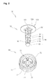
FIG. 2 is a exploded perspective view of the clip.FIG. 3 is a cross-sectional view of the installed state of the clip. -
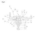
FIG. 4 is another cross-sectional view of the installed state of the clip. -
FIG. 5 is a cross-sectional view of the provisionally fastened state of the pin. -
FIG. 6 is a cross-sectional view of the provisionally fastened state of the pin. -
FIG. 7 is a perspective view of the grommet. -
FIG. 8 is another perspective view of the grommet. -
FIG. 9 is a front view of the grommet. -
FIG. 10 is a side view of the grommet. -
FIG. 11 is a plan view of the grommet. -
FIG. 12 is a bottom view of the grommet. -
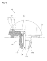
FIG. 13 is a front view in which half of the grommet is a cross-sectional view. -
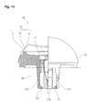
FIG. 14 is a side view in which half of the grommet is a cross-sectional view. -
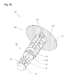
FIG. 15 is a perspective view of the pin. -
FIG. 16 is another perspective view of the pin. -
FIG. 17 is a front view of the pin. -
FIG. 18 is a side view in which half of the pin is a cross-sectional view. -
FIG. 19 is a plan view of the pin. -
FIG. 20 is a partially enlarged view of the pin. -
FIG. 21 is a cross-sectional view along the line A-A inFIG. 18 . -
FIG. 22 is a diagram for describing the coupled state between the projecting wall of the grommet and the projecting part of the pin. -
FIG. 23 is a partial plan view of the grommet for describing a second embodiment of the present invention. -
FIG. 24 is a partial plan view of the grommet for describing a third embodiment of the present invention. -
FIG. 25 is a cross-sectional view of the installed state of the clip, illustrating a fourth embodiment of the present invention. -
FIG. 26 is another cross-sectional view of the installed state of the clip, illustrating a fourth embodiment of the present invention. -
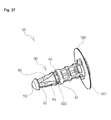
FIG. 27 is a perspective view of the pin, illustrating a fifth embodiment of the present invention. -
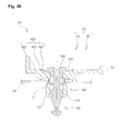
FIG. 28 is a cross-sectional view of the installed state of the clip, illustrating a fifth embodiment of the present invention. -
FIG. 29 is a cross-sectional view illustrating a state in which the pin inFIG. 28 is rotated. -
FIG. 30 is an enlarged view of the A portion surrounded by the circle inFIG. 29 . -
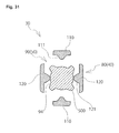
FIG. 31 is a cross-sectional view along the line X-X inFIG. 28 . -
FIG. 32 is a cross-sectional view along the line Y-Y inFIG. 29 . - In
FIG. 1 , numeral 10 indicates a member fastening structure, and themember fastening structure 10 is for fastening a bumper (not illustrated), being one example of a part, to abase 20, for example being an automobile body, although not illustrated, by way of aclip 30 configuring a portion of a bumper retainer (not illustrated).
Aninstallation hole 21 for installing theclip 30 is provided on the base 20 as illustrated inFIG. 1 . Theinstallation hole 21 runs through the base 20 top to bottom, and is formed in a noncircular, for example square shape. - The
installation hole 21 is formed in a square shape, but the present invention is not limited to this, and theinstallation hole 21 may be in a noncircular shape in which theclip 30 does not rotate.
Meanwhile, an automobile body is illustrated as an example of thebase 20, but the present invention is not limited to this, and is not limited to use for automobiles, and may be used for other vehicles, or buildings, furniture, office equipment, or the like.
Also, a bumper is illustrated as an example of the part, but the present invention is not limited to this. Also, the bumper retainer (not illustrated) and theclip 30 are considered as a portion of the part, but this point is to be discussed as "modes of parts." - Furthermore, the
clip 30 is configured as a portion of the bumper retainer, but the present invention is not limited to this, and theclip 30 may be configured separately from the bumper retainer. - The
clip 30, broadly divided, has the following configuration, as illustrated inFIGS. 1 and2 .
The following (1) to (3) are to be described. - The configuration of the
clip 30 is not limited to the above (1) to (3). - The
grommet 40 configures a portion of the bumper retainer (not illustrated), is bound to thebase 20 by being installed in theinstallation hole 21 of thebase 20 and inserting apin 50 to be described, as illustrated inFIGS. 1 to 4 , and constitutes the installation member. The bumper retainer is bound to thebase 20 by way of thegrommet 40. Thegrommet 40 is integrally molded with a synthetic resin having a suitable degree of elasticity and rigidity. - The
grommet 40 is configured as a portion of the bumper retainer, but the present invention is not limited to this, and the grommet may be configured separately from the bumper retainer. Also, thegrommet 40 is illustrated as an example of the installation member, but the present invention is not limited to this.
Specifically, thegrommet 40 has the following parts, as illustrated inFIGS. 7 to 14 .
The following (1) and (2) are to be described. - The parts of the
grommet 40 are not limited to the above (1) and (2). - The
pin 50 is for fastening thegrommet 40 to thebase 20 by being inserted in to thegrommet 40, as illustrated inFIGS. 1 to 4 , and constitutes the leg member. Thepin 50 is integrally molded with a synthetic resin having a suitable degree of elasticity and rigidity. - A pin is illustrated as the leg member, but the leg member is not limited to this.
Specifically, thepin 50 has the following parts, as illustrated inFIGS. 15 to 21 .
The following (1) and (2) are to be described. - The parts of the
grommet 40 are not limited to the above (1) and (2). - The packing 60 is positioned between the base 20 and the
grommet 40 as illustrated inFIG. 1 , and is for preventing intrusion of water from theinstallation hole 21 of thebase 20. The packing 60 is formed with a material endowed with elasticity, and for example, is formed in a square plate form. Asquare center hole 61, conforming to the external shape of theleg part 80 of thegrommet 40 to be described, is formed in the center of the packing 60, running through from top to bottom. - The collar-
form part 70 configures a portion of the bumper retainer (not illustrated), and contacts with thebase 20, as illustrated inFIGS. 1 to 4 . - Specifically, the collar-
form part 70 is formed in an oblong disk shape in planar section, and the outer diameter is set larger than the inner diameter of theinstallation hole 21 of thebase 20.
The collar-form part 70 is configured as a portion of the bumper retainer, but the present invention is not limited to this, and the collar-form part 70 may be formed separately from the bumper retainer. Also, the collar-form part 70 is placed directly in contact with the base, but the present invention is not limited to this, and the collar-form part 70 may be placed indirectly in contact with the base 20 by way of the bumper retainer in the case when being configured separately from the bumper retainer. - The collar-
form part 70 has the following parts, as illustrated inFIGS. 7 to 14 . - The following (1) to (3) are to be described.
- The parts of the collar-
form part 70 are not limited to the above (1) to (3). - The through-
hole 71 is for theshaft part 90 of thepin 50 to be inserted through, as illustrated inFIGS. 1 to 4 . - Specifically, the through-
hole 71 is formed in a circular shape in the center of the collar-form part 70, and runs through from top to bottom, that is, in the vertical direction inFIG. 1 . - The
wall part 72 extends toward the direction of insertion of thepin 50, as illustrated inFIGS. 1 to 4 .
Specifically, thewall part 72 is centered on the through-hole 71, is shaped in an annular rib form being one size larger, and projects from an upper face of the collar-form part 70. Thewall part 72 is formed in a trapezoidal shape in section with aninclined surface 74 being oriented toward the center of the through-hole 71. Theinclined surface 74 is positioned on an inner wall, more specifically an inner side face, of thewall part 72, and is inclined downward toward the direction of the through-hole 71. Also, atop face 75, being an upper face of thewall part 72, is formed in parallel with an upper face of thewall part 72, and a connectingpart 76 is formed on a corner part between thetop face 75 and theinclined surface 74. - The projecting
wall 73 is positioned between the through-hole 71 and thewall part 72 as illustrated inFIGS. 2 and22 , and contacts with a projectingpart 103 formed on a lower side of theflange 100 of the pin when thepin 50 to be described is rotated, to guide in the direction that theshaft part 90 of thepin 50 comes out from the through-hole 71. - Specifically, four projecting
walls 73 are formed radially centered on the through-hole 71, projecting from the upper face of the collar-form part 70 and being formed in symmetrical shapes with respect to front to back in the circumferential direction of the collar-form part 70. Each projectingwall 73 is formed in an "arrowhead" or "arrow mark" shape in planar section, and a triangularly shaped pointed tip of the tip part of the "arrowhead" or "arrow mark" is oriented toward the through-hole 71.Inclined surfaces wall 73. - The projecting
wall 73 contacts with the projectingpart 103 projecting from a lower face of theflange 100 of thepin 50 to be described. That is, when theshaft part 90 of thepin 50 is inserted deeply in the through-hole 71 of thegrommet 40, the projectingpart 103 projecting from the lower face of theflange 100 is positioned on the upper face of the collar-form part 70. When thepin 50 is rotated in this state, the projectingpart 103 and the projectingwall 73 projecting from the upper face of the collar-form part 70 contact with each other. When thepin 50 is rotated further, theflange 100 of thepin 50 is guided in the direction of floating up from the upper face of the collar-form part 70 of thegrommet 40 by the contact between aninclined surface 104, to be described, of the projectingpart 103 and eitherinclined surface 77 of theinclined surfaces wall 73. - The
leg part 80 hangs down from the periphery of the through-hole 71, and has a plurality, for example a total of four, first and secondelastic leg pieces installation hole 21 provided on thebase 20 by insertion of thepin 50, as illustrated inFIGS. 3 ,4 , and8 . Theleg part 80 is formed with the total of four first and secondelastic leg pieces hole 71, as illustrated inFIGS. 8 and12 . - A total of four
elastic leg pieces
Also, the external shape of theleg part 80, being configured with the total of four first and secondelastic leg pieces installation hole 21 of thebase 20.
Two firstelastic leg pieces 110 of the total of four first and secondelastic leg pieces part 111 is provided on each of the mutually opposite inner faces, as illustrated inFIGS. 8 ,12 , and13 . - The first
elastic leg pieces 110 are inserted into theinstallation hole 21 of thebase 20, and in that state, theshaft part 90 of thepin 50 to be described is inserted by way of the through-hole 71, whereby the rib-form first raisedpart 111 is pushed by the outer perimeter of theshaft part 90, whereby the firstelastic leg pieces 110 are spread open in the direction of being moved apart from each other, as illustrated inFIG. 4 . Therefore, thegrommet 40 is fastened to theinstallation hole 21 of the base 20 by holding the base 20 from top to bottom between the lower face of the collar-form part 70 and the spread-open pair of firstelastic leg pieces 110. That is, the bumper retainer is fastened to the base 20 because thegrommet 40 is configured as a portion of the bumper retainer (not illustrated). - Meanwhile, two second
elastic leg pieces 120 of the total of four first and secondelastic leg pieces part 121, being bent in an L-shape in cross-section, is provided on each of the mutually opposite inner faces of the leading-end parts, as illustrated inFIGS. 8 ,12 , and14 .
The secondelastic leg pieces 120 are inserted into theinstallation hole 21 of thebase 20, and in that state, theshaft part 90 of thepin 50 to be described is inserted by way of the through-hole 71, whereby the claw-form second raisedpart 121 is fitted into a recessedpart 94, to be described, of theshaft part 90, whereby movement in the direction of insertion of theshaft part 90 of thepin 50 is prevented, as illustrated inFIG. 3 . - The
shaft part 90 hangs down from theflange 100 to be described, as illustrated inFIGS. 15 to 18 . - Specifically, the
shaft part 90 hangs down from the lower face of theflange 100, the entire body is formed in a roughly square-columnar shape, and a leading-end part is pointed in a tapered form.
Theshaft part 90 has the following parts, as illustrated inFIGS. 15 to 18 .
The parts of theshaft part 90 are not limited to the following (1) to (6). - The wide-
diameter part 91 is positioned at midcourse of the length of theshaft part 90, and is set to a comparatively wide diameter, as illustrated inFIGS. 15 to 18 . - The wide-
diameter part 91 spreads open the firstelastic leg pieces 110 by coming into the interval of the firstelastic leg pieces 110 when theshaft part 90 of thepin 50 is inserted into the hollow inner part of theleg part 80 by way of the through-hole 71, as illustrated inFIG. 4 . - The narrow-
diameter part 92 is positioned on the leading-end part of theshaft part 90, and is set to a narrower diameter compared with the wide-diameter part 91, as illustrated inFIGS. 15 to 18 . - The first
elastic leg pieces 110 are not spread open at a position where narrow-diameter part 92 comes into the interval of thefirst leg pieces 110, as illustrated inFIG. 6 . - The
cam part 93 is positioned between the wide-diameter part 91 and the narrow-diameter part 92, and becomes gradually thicker going toward the wide-diameter part 91 from the narrow-diameter part 92, as illustrated inFIGS. 15 to 18 . - As illustrated in
FIG. 6 , when theshaft part 90 is pushed into the through-hole 71 from a position where the narrow-diameter part 92 has come into the interval of the firstelastic leg pieces 110, the rib-form first raisedparts 111 of the firstelastic leg pieces 110 contact with thecam part 93. When theshaft part 90 is pushed in further, the rib-form first raisedparts 111 of the firstelastic leg pieces 110 are pushed by the outer perimeter of thecam part 93 because thecam part 93 becomes gradually thicker going toward the wide-diameter part 91, and the firstelastic leg pieces 110 accordingly increase in diameter and reach the wide-diameter part 91 as illustrated inFIG. 4 . - The recessed
part 94 is formed on the wide-diameter part 91 and sinks in a recessed form as illustrated inFIGS. 15 to 18 .
The claw-form second raisedpart 121 of the secondelastic leg piece 120 is fitted into the recessedpart 94, whereby movement in the axial direction of theshaft part 90 of thepin 50 against thegrommet 40 is prevented, as illustrated inFIG. 3 . - The slip-out-preventing
part 95 is positioned on the leading-end part of theshaft part 90 adjacent to the narrow-diameter part 92, is thicker than the narrow-diameter part 92, and extends in a tapered umbrella shape or conical shape, as illustrated inFIGS. 15 to 18 . - The slip-out-preventing
part 95 contacts with the rib-form first raisedparts 111 of the firstelastic leg pieces 110 when theshaft part 90 of thepin 50 is inserted into the hollow inner part of theleg part 80 by way of the through-hole 71, and passes through the interval of the first raisedparts 111 in a manner so as to push open the firstelastic leg pieces 110. When the slip-out-preventingpart 95 passes through the interval of the first raisedparts 111, the firstelastic leg pieces 110 return by the return force of the resin, whereby theshaft part 90 is prevented from slipping out.
At the same time, the slip-out-preventingpart 95 contacts with the claw-form second raisedparts 121 of the secondelastic leg pieces 120, and passes through the interval of the second raisedparts 121 in a manner so as to push open the secondelastic leg pieces 120. When the slip-out-preventingpart 95 passes through the interval of the second raisedparts 121, the secondelastic leg pieces 120 return by the return force of the resin, whereby theshaft part 90 is prevented from slipping out. - A total of four
guide ribs 96 are formed following the axial direction of theshaft part 90, extending radially from the center of theshaft part 90, as illustrated inFIGS. 15 to 18 .
Theguide ribs 96 are fitted inside the gaps between adjacent firstelastic leg pieces 110 and secondelastic leg pieces 120 when theshaft part 90 of thepin 50 is inserted into the hollow inner part of theleg part 80 by way of the through-hole 71, so that theshaft part 90 of thepin 50 inside the hollow inner part of theleg part 80 does not rotate inadvertently. - The
flange 100 extends in a disk form from the upper-end part of theshaft part 90, and its outer diameter is set larger than the inner diameter of the through-hole 71. - Specifically, the
flange 100 has the following parts, as illustrated inFIGS. 15 to 19 . - The parts of the
flange 100 are not limited to the following (1) to (3). - The
elastic body 101 is thinly formed, extending in a straight shape from the outer perimeter of theflange 100, as illustrated inFIGS. 17 and18 . - Specifically, the
elastic body 101 extends in an annular form from the lower side of theflange 100. In the case when the thickness of theflange 100 is set to 2 mm, for example, the thickness of theelastic body 101 is set to one eighth, being 0.25 mm.
Theelastic body 101 contacts with the projectingwall 73 projecting from the upper face of the collar-form part 70 of thegrommet 40. That is, when theshaft part 90 of thepin 50 is inserted into the through-hole 71 of thegrommet 40, the lower face of theelastic body 101 contacts with thetop face 75 being the upper wall of thewall part 72 projecting from the upper face of the collar-form part 70. When theshaft 90 is inserted more deeply, the lower face of theelastic body 101 is pushed by the angular connectingpart 76 between thetop face 75 and theinclined surface 74 being positioned on the inner side face of thewall part 72, and becomes in a bent-back state as illustrated inFIGS. 3 and4 . In this position where theflange 101 is in the bent-back state, as illustrated inFIG. 3 , the claw-form second raisedparts 121 of the secondelastic leg pieces 120 of thegrommet 40 are fitted into the recessedparts 94 of theshaft part 90 of thepin 50, whereby movement in the axial direction of theshaft part 90 of thepin 50 against thegrommet 40 is prevented. Therefore, the state in which theelastic body 101 is pressed against the angular connectingpart 76 in the bent-back state is maintained. - The jig-
coupling part 102, although not illustrated, is for coupling with, for example, a "+" (plus) screwdriver or other jig, and has, for example, a + (plus) slot.
A screwdriver is illustrated as an example of a jig, but [the present invention] is not limited to this. Also, the jig-coupling part 102 is not limited to a + slot. - The projecting
part 103 is positioned on the lower side of theflange 100, projects outward in the radial direction from the outer perimeter of theshaft part 90, and has at least oneinclined surface 104, as illustrated inFIGS. 15 ,17 , and20 .
Specifically, the projectingpart 103 is formed in a triangular-columnar shape, and theinclined surface 104 is oriented in the outer perimeter direction of theshaft part 90. A pair of projectingparts 103 is formed in the diameter direction of theshaft part 90. - A pair of projecting
parts 103 is formed, but the present invention is not limited to this, and one or three or more may be formed. Also, oneinclined surface 104 is formed on one side in the circumferential direction of theflange 100, but the present invention is not limited to this, and although not illustrated, two inclined surfaces may be formed on both sides in the circumferential direction of theflange 100, and the projectingparts 103 may be formed in symmetrical shapes with respect to front to back in the circumferential direction of theflange 100. Thus, by forming the projecting parts in symmetrical shapes with respect to front to back in the circumferential direction, the production of thepin 50 is made simple and convenient, and directionality in the method of rotation of thepin 50 is eliminated, whereby the operability can be improved. - The projecting
part 103 contacts with the projectingwall 73 projecting from the upper face of the collar-form part 70 of thegrommet 40, as illustrated inFIG. 22 . That is, when theshaft part 90 of thepin 50 is inserted deeply into the through-hole 71 of thegrommet 40, the projectingpart 103 projecting from the lower face of theflange 100 is positioned on the upper face of the collar-form part 70. When thepin 50 is rotated in this state, the projectingpart 103 and the projectingwall 73 projecting from the upper face of the collar-form part 70 come into contact with each other. When thepin 50 is rotated further, theflange 100 of thepin 50 is guided in the direction of floating up from the upper face of the collar-form part 70 of thegrommet 40 by the contact between theinclined surface 104 of the projectingpart 103 and eitherinclined surface 77 of theinclined surfaces wall 73. - The method of installation of the
clip 30 including thegrommet 40 and thepin 50 having the above configuration is next described. - First, the
pin 50 and the packing 60 are assembled in advance on thegrommet 40.
Thegrommet 40 may be installed with thepin 50 and the packing 60 when installing on thebase 20.
First, theleg part 80 of thegrommet 40 is inserted correctly in thecenter hole 61 of the packing 60, and the packing 60 is positioned beneath the lower face of the collar-form part 70. - Next, the
shaft part 90 of thepin 50 is inserted correctly in the through-hole 71 of thegrommet 40 as illustrated inFIGS. 5 and6 .
When theshaft part 90 of thepin 50 is inserted, theshaft part 90 of thepin 50 is inserted into the hollow inner part of theleg part 80 by way of the through-hole 71. After that, the slip-out-preventingpart 95 on the leading-end part of theshaft part 90 contacts with the first raisedparts 111 of the firstelastic leg pieces 110 and the second raisedparts 121 of the secondelastic leg pieces 120, and passes through the interval of the first raisedparts 111 and the interval of the second raisedparts 121 in a manner so as to push open the firstelastic leg pieces 110 and the second raisedparts 121, and the first raisedparts 111 and the second raisedparts 121 are positioned on the narrow-diameter part 92 of theshaft part 90. Therefore, theshaft part 90 does not slip out from the hollow inner part of theleg part 80, and thepin 50 is provisionally fastened to thegrommet 40. - Next, the
leg part 80 of thegrommet 40 is inserted correctly in theinstallation hole 21 of the base 20 as illustrated inFIGS. 3 and4 .
When theleg part 80 of thegrommet 40 is inserted, the lower face of the collar-form part 70 contacts with the upper surface of the base 20 by way of the packing 60.
After that, theflange 100 of thepin 50 is pushed into thegrommet 40 as illustrated inFIGS. 3 and4 . - When the
pin 50 is pushed in, theshaft part 90 advances through the hollow inner part of theleg part 80, and the firstelastic leg pieces 110 of thegrommet 40 are pushed open by the wide-diameter part 91, whereby outer diameter of theleg part 80 of thegrommet 40 is spread open as illustrated inFIG. 4 . Therefore, thegrommet 40 is fastened to theinstallation hole 21 of the base 20 by holding the base 20 from top to bottom between the lower face of the collar-form part 70 and the spread-open pair of firstelastic leg pieces 110. That is, the bumper retainer is fastened to the base 20 because thegrommet 40 is configured as a portion of the bumper retainer (not illustrated). - At the same time, the claw-form second raised
parts 121 of the secondelastic leg pieces 120 of thegrommet 40 are fitted inside the recessedparts 94 of thepin 50 as illustrated inFIG. 3 , whereby movement in the direction of insertion of theshaft part 90 of thepin 50 is prevented.
Meanwhile, theelastic body 101 of thepin 50 contacts with the projectingwall 73 projecting from the upper face of the collar-form part 70 of thegrommet 40 as illustrated inFIGS. 3 and4 . That is, when theshaft part 90 of thepin 50 is inserted into the through-hole 71 of thegrommet 40, the lower face of theelastic body 101 contacts with thetop face 75 being the upper face of thewall part 72 projecting from the upper face of the collar-form part 70. When theshaft part 90 is inserted more deeply, the lower face of theelastic body 101 is pushed by the angular connectingpart 76 between thetop face 75 and theinclined surface 74 being positioned on the inner side face of thewall part 72, and becomes in a bent-back state. In this position where theelastic body 101 is in the bent-back state, as illustrated inFIG. 3 , the claw-form second raisedparts 121 of the secondelastic leg pieces 120 of thegrommet 40 are fitted into the recessedparts 94 of theshaft part 90 of thepin 50, whereby movement in the axial direction of theshaft part 90 of thepin 50 against thegrommet 40 is prevented. Therefore, the state in which theelastic body 101 is pressed against the angular connectingpart 76 in the bent-back state is maintained. - The method of removal of the installed
clip 30, on the other hand, is described. - Although not illustrated, a "+" (plus) screwdriver or other jig is coupled in the jig-
coupling part 102, being a + (plus) slot, of thepin 50, and theflange 100 of thepin 50 is rotated in one direction, for example, counterclockwise.
When theflange 100 of thepin 50 is rotated, the projectingpart 103 projecting from the lower face of theflange 100 contacts with the projectingwall 73 projecting from the upper face of the collar-form part 70. - When the
flange 100 of thepin 50 is rotated further, as illustrated inFIG. 22 , theflange 100 of thepin 50 is guided in the direction of floating up from the upper face of the collar-form part 70 of thegrommet 40 by the contact between theinclined surface 104 of the projectingpart 103 and eitherinclined surface 77 of theinclined surfaces wall 73.
When theflange 100 of thepin 50 ascends, theshaft part 90 moves in the direction of coming out from the hollow inner part of theleg part 80, that is, upward, whereby the claw-form second raisedparts 121 of the secondelastic leg pieces 120 of thegrommet 40, having been fitted in the recessedparts 94 of theshaft 90, are decoupled. Therefore, the firstelastic leg pieces 110 of thegrommet 40 move from the wide-diameter part 91 to the narrow-diameter part 92 of theshaft part 90, whereby the outer diameter of theleg part 80 of thegrommet 40 contracts. - Therefore, the
leg part 80 of thegrommet 40 can be pulled out from theinstallation hole 21 of thebase 20.
At this time, thepin 50 maintains the state of being provisionally fastened to thegrommet 40. - A second embodiment of the present invention is next described using
FIG. 23 .
A characteristic of the present embodiment is that a projectingwall 200 projecting from the upper face of the collar-form part 70 of thegrommet 40 is formed as an oblong in planar section, as illustrated inFIG. 23 . - The
oblong projecting wall 200 has a symmetrical shape with respect to front to back in the circumferential direction of the collar-form part 70.
Also, in the description of the present embodiment, the same symbols are used for the same portions of the configuration as in the first embodiment previously described usingFIGS. 1 to 22 , and the descriptions are omitted. - A third embodiment of the present invention is next described using
FIG. 24 . - A characteristic of the present embodiment is in that a projecting
wall 210 projecting from the upper face of the collar-form part 70 of thegrommet 40 is formed as a rectangle in planar section, as illustrated inFIG. 24 .
The rectangular projectingwall 210 has a symmetrical shape with respect to front to back in the circumferential direction of the collar-form part 70.
The projectingwall 73 is formed in an "arrowhead" or "arrow mark" shape in planar section in the first embodiment previously described usingFIGS. 1 to 22 , the projectingwall 200 is formed as an oblong in planar section in the second embodiment described usingFIG. 23 , and the projectingwall 210 is formed as a rectangle in planar section in the present embodiment, but [the present invention] is not limited to these shapes, as it is sufficient that the projectingwalls form part 70. - Also, in the description of the present embodiment, the same symbols are used for the same portions of the configuration as in the first embodiment, and the descriptions are omitted.
- A fourth embodiment of the present invention is next described using
FIGS. 25 and26 .
A characteristic of the present embodiment is that awall part 400 projecting from the upper face of the collar-form part 70 of thegrommet 40 is formed in a step form as illustrated inFIGS. 25 and26 , rather than being in a rib form as is thewall part 72 in the first embodiment previously described usingFIGS. 1 to 22 . - That is, the
wall part 400 is configured with aninclined surface 401 being inclined diagonally upward in the outer perimeter direction from the upper face of the collar-form part 70, atop face 402 being an upper face of thewall part 400, and a connectingpart 403 being positioned in a corner part between theinclined surface 401 and thetop face 402.
Also, in the description of the present embodiment, the same symbols are used for the same portions of the configuration as in the first embodiment, and the descriptions are omitted. - A fifth embodiment of the present invention is next described using
FIGS. 27 to 32 . - A characteristic of the present embodiment is firstly that the "projecting
part 103" and the "inclined surface 104" of the pin 50 (leg member) of the first embodiment previously described usingFIGS. 1 to 22 are omitted, and in place of these, a "lock-releasingpart 500" is formed in the circumferential direction of the recessedpart 94 of the pin 50 (leg member), and the lock-releasingpart 500 is made as a "projecting part," as illustrated inFIGS. 27 and29 to32 .
Secondly, a characteristic of the present embodiment is that the "projectingwall 73" and the "inclined surface 77" of the grommet 40 (installation member) of the first embodiment previously described are omitted, and in place of these, the "second raisedpart 121" of the secondelastic leg piece 120 of the grommet 40 (installation member) is used also as a "projecting wall," as illustrated inFIGS. 27 to 32 . - A plurality of lock-releasing
parts 500 is provided radially, for example a total of four at 90-degree intervals, in the circumferential direction of theshaft part 90 of thepin 50, as illustrated inFIGS. 31 and32 . Also, the lock-releasingparts 500 are positioned between the wide-diameter part 91 and the narrow-diameter part 92 of theshaft part 90, and extend in the axial direction of theshaft part 90, as illustrated inFIGS. 27 ,29 , and30 .
Aninclined surface 501, contracting in diameter toward the direction of the narrow-diameter part 92, that is, being inclined downward, is formed on the outer side face of the lock-releasingpart 500, as illustrated inFIG. 30 . - Four lock-releasing
parts 500 are provided, but [the present invention] is not limited to this, and one, two, three, or five or more may be provided.
Also, in the description of the present embodiment, the same symbols are used for the same portions of the configuration as in the first embodiment, and the descriptions are omitted. - The method of installation of the
clip 30 including thegrommet 40 and thepin 50 having the above configuration is first described. - When the
shaft part 90 of thepin 50 is inserted into the through-hole 71 of thegrommet 40, the claw-form second raisedparts 121 of the secondelastic leg pieces 120 are fitted into the recessed parts 84 of theshaft part 90 and are thereby locked, as illustrated inFIGS. 29 and31 , and movement in the direction of insertion of theshaft part 90 of thepin 50 is prevented.
At this time, the lower face of theelastic body 101 of thepin 50 is pushed by thewall part 72 projecting from the upper face of the collar-form part 70 of thegrommet 40 and becomes in a bent-back state, as illustrated inFIG. 29 . - Also, in the present embodiment, although not illustrated, the first
elastic leg pieces 110 of thegrommet 40 are spread open whereby thegrommet 40 is fastened to thebase 20, as illustrated inFIG. 4 previously described in the first embodiment. - The method of removal of the installed
clip 30 is next described. - When the
flange 100 of thepin 50 is rotated 45 degrees, the claw-form second raisedparts 121 having been fitted into the recessedparts 94 of theshaft part 90 move from the recessedparts 94 to the lock-releasingparts 500, and ride up on the lock-releasingparts 500, as illustrated inFIGS. 29 ,30 , and32 .
At this time, as illustrated inFIG. 29 , a first force F1 lifting up thepin 50 arises due to a repulsion Fx of theelastic body 101 in the bent-back state, and the locked state is released. - Therefore, movement in the axial direction of the
shaft part 90 of thepin 50 becomes possible, and theshaft part 90 moves in the direction of coming out from the hollow inner part of theleg part 80, that is, upward. At this time, the claw-form second raisedparts 121 move toward the narrow-diameter part 92 of theshaft part 90, and can no longer return to the recessedparts 94.
At the same time, the claw-form second raisedparts 121 contact with theinclined surfaces 501 of the lock-releasingparts 500 when riding up on the lock-releasingparts 500, as illustrated inFIG. 30 . - At this time, as illustrated in
FIG. 30 , a second force F2 lifting up thepin 50 arises on theinclined surfaces 501 due to a repulsion Fy of the claws, and the locked state is released.
In the present embodiment, because the angle of inclination of theinclined surfaces 501 is set gently, the locked state cannot be released by the second force F2 alone, but the locked state is released by a combined force with the first force F1 (F1 + F2). It is also possible to make the angle of inclination of theinclined surfaces 501 as a steep gradient, whereby the locked state can be released by the second force F2 alone. - The entire contents of the specification, claims, drawings, and abstract of Japanese Patent Application No.
2010-102506 filed on April 27, 2010
Claims (6)
- A member fastening structure, comprising:an installation member including a collar-form part having a through-hole in a thickness direction, and elastic leg pieces arranged parallel to each other in a cylindrical form on one side of said collar-form part to form a cylindrical part communicating with said through-hole of the collar-form part and having raised parts formed at inner faces facing each other;a leg member including a flange, and a wide-diameter part and a narrow-diameter part integrally formed with the flange and projecting from said flange continuously at least toward a leading-end side; anda cam part placed rising in a circumferential direction of the wide-diameter part from the narrow-diameter part of said leg member, the raised parts of the elastic leg pieces riding up on the cam part by insertion of said leg member into said installation member to thereby expand said elastic leg pieces,
wherein the structure further comprises, between the installation member and the leg member, a projecting part having at least one inclined surface, and a projecting wall for contacting with the inclined surface of said projecting part and guiding the leg member in a removing direction away from said installation member when said leg member is rotated in a state where said elastic leg pieces are spread open. - A member fastening structure according to claim 1, wherein said projecting wall is provided on said installation member, and is formed in a symmetrical form with respect to front to back in a circumferential direction centered on said through-hole.
- A member fastening structure according to claim 1 or 2, wherein said projecting part is formed on a lower side of said flange of said leg member; and
said projecting wall is formed on said collar-form part of said installation member. - A member fastening structure according to claim 1 or 2, wherein said projecting part is formed between said wide-diameter part and said narrow-diameter part of said leg member; and
said projecting wall is formed on said elastic leg piece of said installation member. - A clip adapted to fasten a member, comprising:a grommet having a collar-form part, a leg part hanging down from said collar-form part, and a through-hole running through from the collar-form part to the leg part; anda pin having a shaft part capable of expanding outwardly said leg part by being inserted into said through-hole, and a flange part extending from said shaft part and having a larger diameter than said through-hole;
wherein between said leg part and said shaft part, a recessed part and a raised part are provided either one on either part, the recessed part and raised part fitting together elastically in a state where said leg part is capable of expanding outwardly, to prevent movement in an axial direction of said shaft part in said through-hole,in a circumferential direction of said recessed part, a lock-releasing part is provided to elastically contact with said raised part released from said recessed part and allowing movement in the axial direction of said shaft part in said through-hole when said flange is rotated in a state where the recessed part and the raised part are fitted together; andsaid lock-releasing part is provided with an inclined surface urging in a direction of releasing said shaft part from said through-hole using an elastic return force of said raised part elastically contacting with the lock-releasing part. - A clip adapted to fasten a member, comprising:a grommet having a collar-form part, a leg part hanging down from said collar-form part, and a through-hole running through from the collar-form part to the leg part; anda pin having a shaft part capable of expanding outwardly said leg part by being inserted into said through-hole, and a flange part extending from said shaft part and having a larger diameter than said through-hole;
wherein between said leg part and said shaft part, a recessed part and a raised part are provided either one on either part, the recessed part and raised part fitting together elastically in a state where said leg part is capable of expanding outwardly, to prevent movement in an axial direction of said shaft part in said through-hole,
a lock-releasing part is provided in a circumferential direction of said recessed part for allowing movement in the axial direction of said shaft part in said through-hole when said flange is rotated in a state where the recessed part and the raised part are fitted together,an elastic body having elasticity is provided on a perimeter edge of said flange,said collar-form part is provided with a wall part to elastically contact with said elastic body in a state where said leg part expands outwardly, andwhen said flange is rotated in the state where said leg part is capable of expanding outwardly, by an elastic return force accumulated in said elastic body, said shaft part is urged in a direction to be released from said through-hole.
Priority Applications (1)
| Application Number | Priority Date | Filing Date | Title |
|---|---|---|---|
| PL11774888T PL2565471T3 (en) | 2010-04-27 | 2011-04-20 | Member fastening structure and member fastening clip |
Applications Claiming Priority (2)
| Application Number | Priority Date | Filing Date | Title |
|---|---|---|---|
| JP2010102506A JP5379068B2 (en) | 2010-04-27 | 2010-04-27 | Member fastening structure |
| PCT/JP2011/059734 WO2011136105A1 (en) | 2010-04-27 | 2011-04-20 | Member fastening structure and member fastening clip |
Publications (3)
| Publication Number | Publication Date |
|---|---|
| EP2565471A1 true EP2565471A1 (en) | 2013-03-06 |
| EP2565471A4 EP2565471A4 (en) | 2016-03-30 |
| EP2565471B1 EP2565471B1 (en) | 2018-07-11 |
Family
ID=44861411
Family Applications (1)
| Application Number | Title | Priority Date | Filing Date |
|---|---|---|---|
| EP11774888.9A Active EP2565471B1 (en) | 2010-04-27 | 2011-04-20 | Member fastening structure and member fastening clip |
Country Status (8)
| Country | Link |
|---|---|
| US (1) | US8926244B2 (en) |
| EP (1) | EP2565471B1 (en) |
| JP (1) | JP5379068B2 (en) |
| KR (1) | KR101439720B1 (en) |
| CN (1) | CN102869891B (en) |
| BR (1) | BR112012027652B1 (en) |
| PL (1) | PL2565471T3 (en) |
| WO (1) | WO2011136105A1 (en) |
Cited By (1)
| Publication number | Priority date | Publication date | Assignee | Title |
|---|---|---|---|---|
| WO2025155557A1 (en) * | 2024-01-16 | 2025-07-24 | Tesla, Inc. | Pin and mold-in grommet for mounting parts on vehicles |
Families Citing this family (45)
| Publication number | Priority date | Publication date | Assignee | Title |
|---|---|---|---|---|
| US9812684B2 (en) | 2010-11-09 | 2017-11-07 | GM Global Technology Operations LLC | Using elastic averaging for alignment of battery stack, fuel cell stack, or other vehicle assembly |
| US9618026B2 (en) | 2012-08-06 | 2017-04-11 | GM Global Technology Operations LLC | Semi-circular alignment features of an elastic averaging alignment system |
| US9463538B2 (en) | 2012-08-13 | 2016-10-11 | GM Global Technology Operations LLC | Alignment system and method thereof |
| DE102012016362B4 (en) * | 2012-08-17 | 2018-09-20 | Bayerische Motoren Werke Aktiengesellschaft | mounting clip |
| US9556890B2 (en) | 2013-01-31 | 2017-01-31 | GM Global Technology Operations LLC | Elastic alignment assembly for aligning mated components and method of reducing positional variation |
| US9388838B2 (en) | 2013-04-04 | 2016-07-12 | GM Global Technology Operations LLC | Elastic retaining assembly for matable components and method of assembling |
| US9278642B2 (en) | 2013-04-04 | 2016-03-08 | GM Global Technology Operations LLC | Elastically deformable flange locator arrangement and method of reducing positional variation |
| US9447840B2 (en) | 2013-06-11 | 2016-09-20 | GM Global Technology Operations LLC | Elastically deformable energy management assembly and method of managing energy absorption |
| US9488205B2 (en) | 2013-07-12 | 2016-11-08 | GM Global Technology Operations LLC | Alignment arrangement for mated components and method |
| US9303667B2 (en) | 2013-07-18 | 2016-04-05 | Gm Global Technology Operations, Llc | Lobular elastic tube alignment system for providing precise four-way alignment of components |
| US9458876B2 (en) | 2013-08-28 | 2016-10-04 | GM Global Technology Operations LLC | Elastically deformable alignment fastener and system |
| US9463831B2 (en) | 2013-09-09 | 2016-10-11 | GM Global Technology Operations LLC | Elastic tube alignment and fastening system for providing precise alignment and fastening of components |
| US9457845B2 (en) | 2013-10-02 | 2016-10-04 | GM Global Technology Operations LLC | Lobular elastic tube alignment and retention system for providing precise alignment of components |
| US9511802B2 (en) | 2013-10-03 | 2016-12-06 | GM Global Technology Operations LLC | Elastically averaged alignment systems and methods |
| US9669774B2 (en) | 2013-10-11 | 2017-06-06 | GM Global Technology Operations LLC | Reconfigurable vehicle interior assembly |
| US9481317B2 (en) | 2013-11-15 | 2016-11-01 | GM Global Technology Operations LLC | Elastically deformable clip and method |
| AU2014359722B2 (en) * | 2013-12-02 | 2016-08-11 | Aesculap Ag | Security seal for medical sterile container |
| US9447806B2 (en) | 2013-12-12 | 2016-09-20 | GM Global Technology Operations LLC | Self-retaining alignment system for providing precise alignment and retention of components |
| US9428123B2 (en) | 2013-12-12 | 2016-08-30 | GM Global Technology Operations LLC | Alignment and retention system for a flexible assembly |
| US9446722B2 (en) | 2013-12-19 | 2016-09-20 | GM Global Technology Operations LLC | Elastic averaging alignment member |
| US9599279B2 (en) | 2013-12-19 | 2017-03-21 | GM Global Technology Operations LLC | Elastically deformable module installation assembly |
| US9541113B2 (en) | 2014-01-09 | 2017-01-10 | GM Global Technology Operations LLC | Elastically averaged alignment systems and methods |
| US9428046B2 (en) | 2014-04-02 | 2016-08-30 | GM Global Technology Operations LLC | Alignment and retention system for laterally slideably engageable mating components |
| FR3020099B1 (en) * | 2014-04-16 | 2017-08-18 | Illinois Tool Works | CLAMP FOR ATTACHING A PANEL TO A SUPPORT, METHOD FOR CARRYING OUT THE SAME, AND AUTOMOTIVE EQUIPMENT |
| US9657807B2 (en) | 2014-04-23 | 2017-05-23 | GM Global Technology Operations LLC | System for elastically averaging assembly of components |
| JP5717221B1 (en) * | 2014-05-14 | 2015-05-13 | 株式会社アイ・ディ・エス | Connector |
| US9429176B2 (en) | 2014-06-30 | 2016-08-30 | GM Global Technology Operations LLC | Elastically averaged alignment systems and methods |
| US9528540B2 (en) | 2014-08-12 | 2016-12-27 | Newfrey Llc | Insertion-locking pin and grommet and related methods |
| US10337530B2 (en) | 2014-08-27 | 2019-07-02 | Robert Bosch Gmbh | Press on heat/splash and engine cooling fan assembly having same |
| US9758110B2 (en) | 2015-01-12 | 2017-09-12 | GM Global Technology Operations LLC | Coupling system |
| US10107319B2 (en) | 2015-03-02 | 2018-10-23 | GM Global Technology Operations LLC | Elastically averaged alignment systems and methods |
| JP6446741B2 (en) * | 2015-03-10 | 2019-01-09 | ポップリベット・ファスナー株式会社 | Fastening and fastening structure |
| JP6552376B2 (en) * | 2015-10-16 | 2019-07-31 | パラマウントベッド株式会社 | Fixing member of bed side fence |
| US10215213B2 (en) | 2016-10-04 | 2019-02-26 | Liberty Hardware Mfg. Corp. | Quick-disconnect fastening system |
| DE102017010602A1 (en) * | 2017-11-16 | 2019-05-16 | A. Raymond Et Cie | fasteners |
| US10900513B2 (en) | 2019-04-02 | 2021-01-26 | Newfrey Llc | Re-usable one-push pin and grommet fastener |
| KR102022993B1 (en) * | 2019-05-02 | 2019-09-19 | 최광수 | Ultrasonic welding machine |
| CN110240224A (en) * | 2019-07-15 | 2019-09-17 | 珠海格力电器股份有限公司 | Mounting structure of light-emitting element and light-emitting device |
| CN110641247A (en) * | 2019-10-25 | 2020-01-03 | 博耐尔汽车电气系统有限公司 | Automobile air conditioner connecting rod installation structure |
| US11788571B2 (en) * | 2020-08-07 | 2023-10-17 | Peri Se | Multi-head bolt and fastener system |
| WO2022114297A1 (en) * | 2020-11-27 | 2022-06-02 | 유한회사 지에스코리아 농업회사법인 | Flowerpot to which fastening members are fastened |
| CN113497370B (en) * | 2021-09-06 | 2021-11-19 | 常州协和光电器件有限公司 | Well-fixed circuit board assembly |
| JP7777423B2 (en) | 2021-10-25 | 2025-11-28 | ポップリベット・ファスナー株式会社 | fastener |
| US12326163B2 (en) | 2022-09-07 | 2025-06-10 | Newfrey Llc | Pin and grommet fastener including pin and grommet having panel retention fingers and pin retention fingers that cooperate with one another to define pin receptacle for receiving the pin |
| JP2025081993A (en) * | 2023-11-16 | 2025-05-28 | 株式会社ニフコ | clip |
Family Cites Families (14)
| Publication number | Priority date | Publication date | Assignee | Title |
|---|---|---|---|---|
| US4674930A (en) * | 1981-12-14 | 1987-06-23 | Hartwell Corporation | Stand-off fastener |
| JPS5991413U (en) * | 1982-12-13 | 1984-06-21 | トヨタ自動車株式会社 | Diesel engine exhaust particulate purification device |
| JPH0645048Y2 (en) * | 1988-05-13 | 1994-11-16 | 日産自動車株式会社 | Plastic rivets |
| JP2512362Y2 (en) | 1990-09-06 | 1996-10-02 | 株式会社ニフコ | Fastener |
| JP2578069Y2 (en) * | 1991-03-11 | 1998-08-06 | 株式会社 ニフコ | Grommet |
| JP3251775B2 (en) * | 1994-06-15 | 2002-01-28 | 株式会社ニフコ | clip |
| JP3297972B2 (en) * | 1995-04-17 | 2002-07-02 | 株式会社パイオラックス | Securing clip |
| CN2285846Y (en) * | 1995-12-10 | 1998-07-08 | 许越男 | Expansion nail |
| US6182482B1 (en) * | 1997-11-18 | 2001-02-06 | Aegis Research | Tamper proof lock assembly and key |
| JP4460192B2 (en) | 2001-05-17 | 2010-05-12 | 株式会社ニフコ | clip |
| FR2882797B1 (en) * | 2005-03-02 | 2007-05-25 | Itw De France Soc Par Actions | ATTACHMENT ADAPTED TO BE FIXED IN A PREDETERMINE CONTOUR CAVITY |
| JP5243749B2 (en) * | 2007-08-09 | 2013-07-24 | 株式会社ニフコ | Clip and support member |
| JP5145129B2 (en) * | 2008-06-24 | 2013-02-13 | 株式会社ニフコ | clip |
| JP5319586B2 (en) * | 2010-03-24 | 2013-10-16 | 株式会社ニフコ | Fastening structure for parts and clip used therefor |
-
2010
- 2010-04-27 JP JP2010102506A patent/JP5379068B2/en active Active
-
2011
- 2011-04-20 EP EP11774888.9A patent/EP2565471B1/en active Active
- 2011-04-20 BR BR112012027652-2A patent/BR112012027652B1/en active IP Right Grant
- 2011-04-20 WO PCT/JP2011/059734 patent/WO2011136105A1/en not_active Ceased
- 2011-04-20 CN CN201180021227.9A patent/CN102869891B/en active Active
- 2011-04-20 US US13/642,982 patent/US8926244B2/en active Active
- 2011-04-20 KR KR1020127026622A patent/KR101439720B1/en active Active
- 2011-04-20 PL PL11774888T patent/PL2565471T3/en unknown
Cited By (1)
| Publication number | Priority date | Publication date | Assignee | Title |
|---|---|---|---|---|
| WO2025155557A1 (en) * | 2024-01-16 | 2025-07-24 | Tesla, Inc. | Pin and mold-in grommet for mounting parts on vehicles |
Also Published As
| Publication number | Publication date |
|---|---|
| CN102869891B (en) | 2014-12-03 |
| BR112012027652B1 (en) | 2019-08-06 |
| US8926244B2 (en) | 2015-01-06 |
| KR20130004333A (en) | 2013-01-09 |
| PL2565471T3 (en) | 2018-12-31 |
| BR112012027652A2 (en) | 2016-08-16 |
| KR101439720B1 (en) | 2014-09-12 |
| JP5379068B2 (en) | 2013-12-25 |
| EP2565471A4 (en) | 2016-03-30 |
| US20130091669A1 (en) | 2013-04-18 |
| EP2565471B1 (en) | 2018-07-11 |
| WO2011136105A1 (en) | 2011-11-03 |
| CN102869891A (en) | 2013-01-09 |
| JP2011231850A (en) | 2011-11-17 |
Similar Documents
| Publication | Publication Date | Title |
|---|---|---|
| US8926244B2 (en) | Member fastening structure and clip for fastening member | |
| US8882421B2 (en) | Fastening structure for part and clip used therein | |
| US10060463B2 (en) | Clip and fastening structure | |
| US9631653B2 (en) | Push-in fastener | |
| EP2496847B1 (en) | Push-in fastener assembly | |
| US8956095B2 (en) | Two-piece clip | |
| CN106979201B (en) | Fastener clip assembly with funnel guide | |
| US8662807B2 (en) | Fastener and structure for fastening a member to be fastened | |
| US6796760B1 (en) | Retention structure for a fastener | |
| US5568675A (en) | Two-piece clip | |
| US20050244250A1 (en) | Clip | |
| US11592050B2 (en) | Apparatus for a captured fastener assembly with expanding grommet | |
| US20110219588A1 (en) | Attachment structure of clip and mounting-subject member | |
| KR20130028949A (en) | Clip | |
| JP2014535028A (en) | Rivet mechanism for fastening panels | |
| US20190078602A1 (en) | Clip | |
| US11933347B2 (en) | Rivet-type fastener | |
| JP4614287B2 (en) | Mounting structure using clips | |
| JP2019015385A (en) | clip | |
| JP2020034024A (en) | Fastener | |
| JP7777423B2 (en) | fastener |
Legal Events
| Date | Code | Title | Description |
|---|---|---|---|
| PUAI | Public reference made under article 153(3) epc to a published international application that has entered the european phase |
Free format text: ORIGINAL CODE: 0009012 |
|
| 17P | Request for examination filed |
Effective date: 20121024 |
|
| AK | Designated contracting states |
Kind code of ref document: A1 Designated state(s): AL AT BE BG CH CY CZ DE DK EE ES FI FR GB GR HR HU IE IS IT LI LT LU LV MC MK MT NL NO PL PT RO RS SE SI SK SM TR |
|
| DAX | Request for extension of the european patent (deleted) | ||
| RA4 | Supplementary search report drawn up and despatched (corrected) |
Effective date: 20160225 |
|
| RIC1 | Information provided on ipc code assigned before grant |
Ipc: F16B 19/10 20060101AFI20160219BHEP |
|
| STAA | Information on the status of an ep patent application or granted ep patent |
Free format text: STATUS: EXAMINATION IS IN PROGRESS |
|
| 17Q | First examination report despatched |
Effective date: 20170324 |
|
| GRAP | Despatch of communication of intention to grant a patent |
Free format text: ORIGINAL CODE: EPIDOSNIGR1 |
|
| STAA | Information on the status of an ep patent application or granted ep patent |
Free format text: STATUS: GRANT OF PATENT IS INTENDED |
|
| INTG | Intention to grant announced |
Effective date: 20180320 |
|
| GRAS | Grant fee paid |
Free format text: ORIGINAL CODE: EPIDOSNIGR3 |
|
| GRAA | (expected) grant |
Free format text: ORIGINAL CODE: 0009210 |
|
| STAA | Information on the status of an ep patent application or granted ep patent |
Free format text: STATUS: THE PATENT HAS BEEN GRANTED |
|
| RIN1 | Information on inventor provided before grant (corrected) |
Inventor name: SASAKI, YUJI |
|
| RAP1 | Party data changed (applicant data changed or rights of an application transferred) |
Owner name: NIFCO INC. |
|
| AK | Designated contracting states |
Kind code of ref document: B1 Designated state(s): AL AT BE BG CH CY CZ DE DK EE ES FI FR GB GR HR HU IE IS IT LI LT LU LV MC MK MT NL NO PL PT RO RS SE SI SK SM TR |
|
| REG | Reference to a national code |
Ref country code: GB Ref legal event code: FG4D |
|
| REG | Reference to a national code |
Ref country code: CH Ref legal event code: EP |
|
| REG | Reference to a national code |
Ref country code: AT Ref legal event code: REF Ref document number: 1017178 Country of ref document: AT Kind code of ref document: T Effective date: 20180715 |
|
| REG | Reference to a national code |
Ref country code: IE Ref legal event code: FG4D |
|
| REG | Reference to a national code |
Ref country code: DE Ref legal event code: R096 Ref document number: 602011049983 Country of ref document: DE |
|
| REG | Reference to a national code |
Ref country code: NL Ref legal event code: MP Effective date: 20180711 |
|
| REG | Reference to a national code |
Ref country code: LT Ref legal event code: MG4D |
|
| REG | Reference to a national code |
Ref country code: AT Ref legal event code: MK05 Ref document number: 1017178 Country of ref document: AT Kind code of ref document: T Effective date: 20180711 |
|
| PG25 | Lapsed in a contracting state [announced via postgrant information from national office to epo] |
Ref country code: NL Free format text: LAPSE BECAUSE OF FAILURE TO SUBMIT A TRANSLATION OF THE DESCRIPTION OR TO PAY THE FEE WITHIN THE PRESCRIBED TIME-LIMIT Effective date: 20180711 |
|
| PG25 | Lapsed in a contracting state [announced via postgrant information from national office to epo] |
Ref country code: LT Free format text: LAPSE BECAUSE OF FAILURE TO SUBMIT A TRANSLATION OF THE DESCRIPTION OR TO PAY THE FEE WITHIN THE PRESCRIBED TIME-LIMIT Effective date: 20180711 Ref country code: FI Free format text: LAPSE BECAUSE OF FAILURE TO SUBMIT A TRANSLATION OF THE DESCRIPTION OR TO PAY THE FEE WITHIN THE PRESCRIBED TIME-LIMIT Effective date: 20180711 Ref country code: AT Free format text: LAPSE BECAUSE OF FAILURE TO SUBMIT A TRANSLATION OF THE DESCRIPTION OR TO PAY THE FEE WITHIN THE PRESCRIBED TIME-LIMIT Effective date: 20180711 Ref country code: RS Free format text: LAPSE BECAUSE OF FAILURE TO SUBMIT A TRANSLATION OF THE DESCRIPTION OR TO PAY THE FEE WITHIN THE PRESCRIBED TIME-LIMIT Effective date: 20180711 Ref country code: GR Free format text: LAPSE BECAUSE OF FAILURE TO SUBMIT A TRANSLATION OF THE DESCRIPTION OR TO PAY THE FEE WITHIN THE PRESCRIBED TIME-LIMIT Effective date: 20181012 Ref country code: NO Free format text: LAPSE BECAUSE OF FAILURE TO SUBMIT A TRANSLATION OF THE DESCRIPTION OR TO PAY THE FEE WITHIN THE PRESCRIBED TIME-LIMIT Effective date: 20181011 Ref country code: IS Free format text: LAPSE BECAUSE OF FAILURE TO SUBMIT A TRANSLATION OF THE DESCRIPTION OR TO PAY THE FEE WITHIN THE PRESCRIBED TIME-LIMIT Effective date: 20181111 Ref country code: BG Free format text: LAPSE BECAUSE OF FAILURE TO SUBMIT A TRANSLATION OF THE DESCRIPTION OR TO PAY THE FEE WITHIN THE PRESCRIBED TIME-LIMIT Effective date: 20181011 Ref country code: SE Free format text: LAPSE BECAUSE OF FAILURE TO SUBMIT A TRANSLATION OF THE DESCRIPTION OR TO PAY THE FEE WITHIN THE PRESCRIBED TIME-LIMIT Effective date: 20180711 |
|
| PG25 | Lapsed in a contracting state [announced via postgrant information from national office to epo] |
Ref country code: HR Free format text: LAPSE BECAUSE OF FAILURE TO SUBMIT A TRANSLATION OF THE DESCRIPTION OR TO PAY THE FEE WITHIN THE PRESCRIBED TIME-LIMIT Effective date: 20180711 Ref country code: LV Free format text: LAPSE BECAUSE OF FAILURE TO SUBMIT A TRANSLATION OF THE DESCRIPTION OR TO PAY THE FEE WITHIN THE PRESCRIBED TIME-LIMIT Effective date: 20180711 Ref country code: AL Free format text: LAPSE BECAUSE OF FAILURE TO SUBMIT A TRANSLATION OF THE DESCRIPTION OR TO PAY THE FEE WITHIN THE PRESCRIBED TIME-LIMIT Effective date: 20180711 Ref country code: ES Free format text: LAPSE BECAUSE OF FAILURE TO SUBMIT A TRANSLATION OF THE DESCRIPTION OR TO PAY THE FEE WITHIN THE PRESCRIBED TIME-LIMIT Effective date: 20180711 |
|
| REG | Reference to a national code |
Ref country code: DE Ref legal event code: R097 Ref document number: 602011049983 Country of ref document: DE |
|
| PG25 | Lapsed in a contracting state [announced via postgrant information from national office to epo] |
Ref country code: EE Free format text: LAPSE BECAUSE OF FAILURE TO SUBMIT A TRANSLATION OF THE DESCRIPTION OR TO PAY THE FEE WITHIN THE PRESCRIBED TIME-LIMIT Effective date: 20180711 Ref country code: RO Free format text: LAPSE BECAUSE OF FAILURE TO SUBMIT A TRANSLATION OF THE DESCRIPTION OR TO PAY THE FEE WITHIN THE PRESCRIBED TIME-LIMIT Effective date: 20180711 Ref country code: IT Free format text: LAPSE BECAUSE OF FAILURE TO SUBMIT A TRANSLATION OF THE DESCRIPTION OR TO PAY THE FEE WITHIN THE PRESCRIBED TIME-LIMIT Effective date: 20180711 |
|
| PLBE | No opposition filed within time limit |
Free format text: ORIGINAL CODE: 0009261 |
|
| STAA | Information on the status of an ep patent application or granted ep patent |
Free format text: STATUS: NO OPPOSITION FILED WITHIN TIME LIMIT |
|
| PG25 | Lapsed in a contracting state [announced via postgrant information from national office to epo] |
Ref country code: DK Free format text: LAPSE BECAUSE OF FAILURE TO SUBMIT A TRANSLATION OF THE DESCRIPTION OR TO PAY THE FEE WITHIN THE PRESCRIBED TIME-LIMIT Effective date: 20180711 Ref country code: SM Free format text: LAPSE BECAUSE OF FAILURE TO SUBMIT A TRANSLATION OF THE DESCRIPTION OR TO PAY THE FEE WITHIN THE PRESCRIBED TIME-LIMIT Effective date: 20180711 Ref country code: SK Free format text: LAPSE BECAUSE OF FAILURE TO SUBMIT A TRANSLATION OF THE DESCRIPTION OR TO PAY THE FEE WITHIN THE PRESCRIBED TIME-LIMIT Effective date: 20180711 |
|
| 26N | No opposition filed |
Effective date: 20190412 |
|
| PG25 | Lapsed in a contracting state [announced via postgrant information from national office to epo] |
Ref country code: SI Free format text: LAPSE BECAUSE OF FAILURE TO SUBMIT A TRANSLATION OF THE DESCRIPTION OR TO PAY THE FEE WITHIN THE PRESCRIBED TIME-LIMIT Effective date: 20180711 |
|
| REG | Reference to a national code |
Ref country code: CH Ref legal event code: PL |
|
| REG | Reference to a national code |
Ref country code: BE Ref legal event code: MM Effective date: 20190430 |
|
| PG25 | Lapsed in a contracting state [announced via postgrant information from national office to epo] |
Ref country code: LU Free format text: LAPSE BECAUSE OF NON-PAYMENT OF DUE FEES Effective date: 20190420 Ref country code: MC Free format text: LAPSE BECAUSE OF FAILURE TO SUBMIT A TRANSLATION OF THE DESCRIPTION OR TO PAY THE FEE WITHIN THE PRESCRIBED TIME-LIMIT Effective date: 20180711 |
|
| PG25 | Lapsed in a contracting state [announced via postgrant information from national office to epo] |
Ref country code: CH Free format text: LAPSE BECAUSE OF NON-PAYMENT OF DUE FEES Effective date: 20190430 Ref country code: LI Free format text: LAPSE BECAUSE OF NON-PAYMENT OF DUE FEES Effective date: 20190430 |
|
| PG25 | Lapsed in a contracting state [announced via postgrant information from national office to epo] |
Ref country code: BE Free format text: LAPSE BECAUSE OF NON-PAYMENT OF DUE FEES Effective date: 20190430 |
|
| PG25 | Lapsed in a contracting state [announced via postgrant information from national office to epo] |
Ref country code: IE Free format text: LAPSE BECAUSE OF NON-PAYMENT OF DUE FEES Effective date: 20190420 |
|
| PG25 | Lapsed in a contracting state [announced via postgrant information from national office to epo] |
Ref country code: PT Free format text: LAPSE BECAUSE OF FAILURE TO SUBMIT A TRANSLATION OF THE DESCRIPTION OR TO PAY THE FEE WITHIN THE PRESCRIBED TIME-LIMIT Effective date: 20181111 |
|
| PG25 | Lapsed in a contracting state [announced via postgrant information from national office to epo] |
Ref country code: CY Free format text: LAPSE BECAUSE OF FAILURE TO SUBMIT A TRANSLATION OF THE DESCRIPTION OR TO PAY THE FEE WITHIN THE PRESCRIBED TIME-LIMIT Effective date: 20180711 |
|
| PG25 | Lapsed in a contracting state [announced via postgrant information from national office to epo] |
Ref country code: MT Free format text: LAPSE BECAUSE OF FAILURE TO SUBMIT A TRANSLATION OF THE DESCRIPTION OR TO PAY THE FEE WITHIN THE PRESCRIBED TIME-LIMIT Effective date: 20180711 Ref country code: HU Free format text: LAPSE BECAUSE OF FAILURE TO SUBMIT A TRANSLATION OF THE DESCRIPTION OR TO PAY THE FEE WITHIN THE PRESCRIBED TIME-LIMIT; INVALID AB INITIO Effective date: 20110420 |
|
| PGFP | Annual fee paid to national office [announced via postgrant information from national office to epo] |
Ref country code: CZ Payment date: 20220325 Year of fee payment: 12 |
|
| PG25 | Lapsed in a contracting state [announced via postgrant information from national office to epo] |
Ref country code: MK Free format text: LAPSE BECAUSE OF FAILURE TO SUBMIT A TRANSLATION OF THE DESCRIPTION OR TO PAY THE FEE WITHIN THE PRESCRIBED TIME-LIMIT Effective date: 20180711 |
|
| PGFP | Annual fee paid to national office [announced via postgrant information from national office to epo] |
Ref country code: TR Payment date: 20220419 Year of fee payment: 12 |
|
| PG25 | Lapsed in a contracting state [announced via postgrant information from national office to epo] |
Ref country code: CZ Free format text: LAPSE BECAUSE OF NON-PAYMENT OF DUE FEES Effective date: 20230420 |
|
| PGFP | Annual fee paid to national office [announced via postgrant information from national office to epo] |
Ref country code: DE Payment date: 20250305 Year of fee payment: 15 |
|
| PGFP | Annual fee paid to national office [announced via postgrant information from national office to epo] |
Ref country code: GB Payment date: 20260313 Year of fee payment: 16 |
|
| PGFP | Annual fee paid to national office [announced via postgrant information from national office to epo] |
Ref country code: FR Payment date: 20260309 Year of fee payment: 16 |
|
| PGFP | Annual fee paid to national office [announced via postgrant information from national office to epo] |
Ref country code: PL Payment date: 20260303 Year of fee payment: 16 |