EP2565426A1 - Cooling flow control module for a turbomachine - Google Patents
Cooling flow control module for a turbomachine Download PDFInfo
- Publication number
- EP2565426A1 EP2565426A1 EP12180668A EP12180668A EP2565426A1 EP 2565426 A1 EP2565426 A1 EP 2565426A1 EP 12180668 A EP12180668 A EP 12180668A EP 12180668 A EP12180668 A EP 12180668A EP 2565426 A1 EP2565426 A1 EP 2565426A1
- Authority
- EP
- European Patent Office
- Prior art keywords
- flow control
- control module
- flow
- side wall
- control member
- Prior art date
- Legal status (The legal status is an assumption and is not a legal conclusion. Google has not performed a legal analysis and makes no representation as to the accuracy of the status listed.)
- Withdrawn
Links
- 238000001816 cooling Methods 0.000 title claims description 16
- 239000012809 cooling fluid Substances 0.000 claims abstract description 4
- 229910052751 metal Inorganic materials 0.000 claims description 6
- 238000000034 method Methods 0.000 claims description 6
- 238000011144 upstream manufacturing Methods 0.000 claims description 4
- 230000001939 inductive effect Effects 0.000 claims 1
- 239000003570 air Substances 0.000 description 33
- 239000007789 gas Substances 0.000 description 4
- 238000002347 injection Methods 0.000 description 3
- 239000007924 injection Substances 0.000 description 3
- 238000002485 combustion reaction Methods 0.000 description 2
- 230000007704 transition Effects 0.000 description 2
- 230000004075 alteration Effects 0.000 description 1
- 239000012080 ambient air Substances 0.000 description 1
- 230000000712 assembly Effects 0.000 description 1
- 238000000429 assembly Methods 0.000 description 1
- 230000008859 change Effects 0.000 description 1
- 230000008602 contraction Effects 0.000 description 1
- 230000001627 detrimental effect Effects 0.000 description 1
- 239000012530 fluid Substances 0.000 description 1
- 239000000446 fuel Substances 0.000 description 1
- 230000003116 impacting effect Effects 0.000 description 1
- 230000005012 migration Effects 0.000 description 1
- 238000013508 migration Methods 0.000 description 1
- 239000000203 mixture Substances 0.000 description 1
- 230000009467 reduction Effects 0.000 description 1
- 238000006467 substitution reaction Methods 0.000 description 1
Images

Classifications
-
- F—MECHANICAL ENGINEERING; LIGHTING; HEATING; WEAPONS; BLASTING
- F01—MACHINES OR ENGINES IN GENERAL; ENGINE PLANTS IN GENERAL; STEAM ENGINES
- F01D—NON-POSITIVE DISPLACEMENT MACHINES OR ENGINES, e.g. STEAM TURBINES
- F01D17/00—Regulating or controlling by varying flow
- F01D17/10—Final actuators
- F01D17/12—Final actuators arranged in stator parts
- F01D17/14—Final actuators arranged in stator parts varying effective cross-sectional area of nozzles or guide conduits
-
- F—MECHANICAL ENGINEERING; LIGHTING; HEATING; WEAPONS; BLASTING
- F02—COMBUSTION ENGINES; HOT-GAS OR COMBUSTION-PRODUCT ENGINE PLANTS
- F02C—GAS-TURBINE PLANTS; AIR INTAKES FOR JET-PROPULSION PLANTS; CONTROLLING FUEL SUPPLY IN AIR-BREATHING JET-PROPULSION PLANTS
- F02C9/00—Controlling gas-turbine plants; Controlling fuel supply in air- breathing jet-propulsion plants
- F02C9/16—Control of working fluid flow
-
- F—MECHANICAL ENGINEERING; LIGHTING; HEATING; WEAPONS; BLASTING
- F02—COMBUSTION ENGINES; HOT-GAS OR COMBUSTION-PRODUCT ENGINE PLANTS
- F02C—GAS-TURBINE PLANTS; AIR INTAKES FOR JET-PROPULSION PLANTS; CONTROLLING FUEL SUPPLY IN AIR-BREATHING JET-PROPULSION PLANTS
- F02C9/00—Controlling gas-turbine plants; Controlling fuel supply in air- breathing jet-propulsion plants
- F02C9/16—Control of working fluid flow
- F02C9/18—Control of working fluid flow by bleeding, bypassing or acting on variable working fluid interconnections between turbines or compressors or their stages
Definitions
- the subject matter disclosed herein relates to the art of turbomachines and, more particularly, to a passively controlled flow control module that guides a cooling fluid flow toward a turbine rotor shaft.
- Gas turbomachines include rotating components that may be subjected to high temperatures.
- rotor components are subjected to high temperatures and temperature gradients that may have a detrimental effect on system performance and durability.
- turbomachines include cooling air systems that deliver compressor discharge air toward the rotor components.
- the compressor discharge air is passed from a compressor discharge plenum onto a turbomachine rotor.
- Rotation of the rotor imparts movement to the compressor discharge air resulting in migration toward other rotor components.
- Rotating component cooling needs vary for various operating conditions. During part load operation, less cooling may be required. Also, less cooling may be required when ambient air temperatures are lower than normal operating conditions.
- Current systems for delivering cooling air toward the rotor include direct injection of compressor discharge air to the rotor, and passing the compressor discharge air through a plurality of injectors distributed about a longitudinal axis of the turbomachine.
- Direct injection does not provide much control over the compressor discharge air. That is, direct injection does not provide much flexibility in varying the compressor discharge air to accommodate various operating conditions.
- Injectors can be controlled to change delivery of the cooling air based on operating conditions.
- a bimetallic strip is incorporated into the injector to control air flow. Changes in temperature cause the bimetallic strip to expand and contract thereby changing a discharge opening and altering cooling flow delivery. Often times, the bimetallic strip pivots a trailing edge portion of the injector to control cooling flow delivery.
- a flow control module for a turbomachine includes an inlet extending to an outlet through a flow passage having at least one side wall.
- a flow control member is arranged within the flow control module.
- the flow control member is secured to the at least one side wall between the inlet and the outlet.
- the flow control member is selectively passively activated to extend into the flow passage to block fluid passing through the flow control module.
- a turbomachine includes a compressor portion having a compressor discharge, and a turbine portion having a first stage.
- the first stage includes a wheel space portion, a shaft extending through the wheel space portion, a rotor mounted to the shaft, and at least one bucket mounted to the rotor.
- a flow control module is arranged down stream from the compressor discharge and upstream from the first stage of the turbine.
- the flow control module includes an inlet extending to an outlet through a flow passage having at least one side wall.
- the inlet is fluidly connected to the compressor discharge and the outlet is fluidly connected to the wheel space portion.
- a flow control member is arranged within the flow control module.
- the flow control member is secured to the at least one side wall between the inlet and the outlet. The flow control member is selectively passively activated to extend into the flow passage to block cooling fluid passing through the flow control module.
- the invention resides in a method of passively controlling flow passing from a compressor discharge toward a turbine rotor includes guiding an air flow from a compressor discharge toward a flow control module positioned upstream of a turbine wheel space, passing the air flow through a flow passage extending through the flow control module, and collapsing a first side wall forming the flow passage toward a second side wall forming the flow passage to constrict the flow control module based on a characteristic of the air flow.
- Turbomachine 2 includes a compressor portion 4 and a turbine portion 6.
- Compressor portion 4 includes a compressor housing 8 and turbine portion 6 includes a turbine housing 10.
- Compressor portion 4 is linked to turbine portion 6 through a common compressor/turbine shaft or rotor 16.
- Compressor portion 4 is also linked to turbine portion 6 through a plurality of circumferentially spaced combustor assemblies, one of which is indicated at 20.
- Combustor assembly 20 is fluidly connected to turbine portion 6 by a transition piece 24.
- Compressor portion 4 includes a compressor discharge plenum 27 that leads to a diffuser 30.
- Compressed air flows from compressor portion 4 into compressor discharge plenum 27 passes through diffuser 30 and into combustor assembly 20.
- the compressed air mixes with fuel to form a combustible mixture that is combusted to form hot gases.
- the hot gases flow through transition piece 24 along a hot gas path (not separately labeled) toward a first stage 32 of turbine portion 6.
- a portion of the compressed air forms an air flow that is passed to a wheel space 34 in turbine portion 6.
- the air flow represents cooling air passing into turbine portion 6.
- the air flow passes from diffuser 30 through a flow control module 40 into wheel space 34.
- flow control module 40 includes an inlet 44 that leads to an outlet 45 through a flow passage 47.
- Flow passage 47 includes first and second opposing side walls 53 and 54 that are joined by third and fourth opposing side walls 56 and 57.
- First side wall 53 includes a curvilinear surface portion 59.
- second side wall 54 includes a curvilinear surface portion 60.
- Third and fourth side walls 56 and 57 include substantially linear surfaces 62 and 64 respectively. Curvilinear surface portions 59 and 60 are shaped so as to guide the cooling flow from diffuser 30 into wheel space 34 at a desired angle.
- curvilinear surfaces 59 and 60 guide the cooling flow into wheel space 34 so as to pass tangentially across rotor 16.
- the air flow is guided in a direction corresponding to a direction of rotation of rotor 16.
- flow control module 40 When operating at peak or near peak output, air flow through flow control module 40 is unimpeded so as to enhance cooling. However, during off-peak operation, the amount of air flow passing into wheel space 34 can be reduced. Reducing the amount of air flow passing into wheel space 34 leads to an increase in air flowing to combustor assembly 20 which, in turn, leads to increased operational efficiency at off-peak operation. Accordingly, flow control module 40 includes a flow control member 80 that selectively, passively, extends into flow passage 47 during off-peak operation such as shown in FIG. 4 .
- the term passively should be understood to mean that flow control member 80 extends into flow passage 47 based on a parameter of the air flow, not as a result of a particular control input.
- flow control member 80 includes a bi-metallic element 86 embedded in first side wall 53. Bi-metallic element 86 includes a first member 90 that is joined to a second member 91.
- first and second members 90 and 91 When exposed to particular temperature ranges, first and second members 90 and 91 expand and contract relative to one another. In the present case, when exposed to air flow during peak or near peak operation, first and second members 90 and 91 conform to curvilinear surface portion 59 such as shown in FIG. 3 . However, when exposed to air flow during off-peak operations, first member 90 contracts at a rate that is distinct from a rate of contraction of second member 91 resulting in flow control member 80 bulging or extending into flow passage 47 such as shown in FIG. 4 . In this manner, flow control member 80 reduces an overall air flow passing to wheel space 34. The reduction in air flow passing into wheel space 34 leads to an increase in compressor flow passing to combustor assembly 20. The increase in compressor flow to combustor assembly 20 leads to more complete combustion at off-peak operation so as to reduce emissions and increase efficiency.
- Flow control module 140 includes an inlet 144 that leads to an outlet 145 through a flow passage 147.
- Flow passage 147 includes first and second opposing side walls 153 and 154 that are joined by a third side wall 156 and a fourth side wall (not shown).
- First side wall 153 includes a curvilinear surface portion 159.
- second side wall 154 includes a curvilinear surface portion 160.
- Third side wall 156 includes a substantially linear or smooth surface 162.
- the fourth side wall (not shown) likewise includes a substantially linear or smooth surface (also not shown).
- curvilinear surface portions 159 and 160 are shaped so as to guide the cooling flow from diffuser 30 into wheel space 34 at an angle.
- Flow control module 140 includes a flow control member 180 that selectively, passively, extends into flow passage 147 during off-peak operation.
- flow control member 180 includes a bi-metallic element 186 embedded in third side wall 156. More specifically, flow control member 180 extends across or spans flow passage 147 and connects with first and second side walls 153 and 154.
- Bi-metallic element 186 includes a first member 190 that is joined to a second member (not shown). In a manner similar to that described above, bi-metallic element extends into flow passage 147 during off-peak operation in order to reduce air flow passing into wheel space 34 and increase compressor flow passing to combustor assembly 20 to enhance combustion and reduce emissions.
Landscapes
- Engineering & Computer Science (AREA)
- Chemical & Material Sciences (AREA)
- Combustion & Propulsion (AREA)
- Mechanical Engineering (AREA)
- General Engineering & Computer Science (AREA)
- Physics & Mathematics (AREA)
- Fluid Mechanics (AREA)
- Structures Of Non-Positive Displacement Pumps (AREA)
Abstract
Description
- The subject matter disclosed herein relates to the art of turbomachines and, more particularly, to a passively controlled flow control module that guides a cooling fluid flow toward a turbine rotor shaft.
- Gas turbomachines include rotating components that may be subjected to high temperatures. In a turbine, rotor components are subjected to high temperatures and temperature gradients that may have a detrimental effect on system performance and durability. In order to enhance system performance and extend component life, turbomachines include cooling air systems that deliver compressor discharge air toward the rotor components. Typically, the compressor discharge air is passed from a compressor discharge plenum onto a turbomachine rotor. Rotation of the rotor imparts movement to the compressor discharge air resulting in migration toward other rotor components. Rotating component cooling needs vary for various operating conditions. During part load operation, less cooling may be required. Also, less cooling may be required when ambient air temperatures are lower than normal operating conditions.
- Current systems for delivering cooling air toward the rotor include direct injection of compressor discharge air to the rotor, and passing the compressor discharge air through a plurality of injectors distributed about a longitudinal axis of the turbomachine. Direct injection does not provide much control over the compressor discharge air. That is, direct injection does not provide much flexibility in varying the compressor discharge air to accommodate various operating conditions. Injectors can be controlled to change delivery of the cooling air based on operating conditions. In some cases, a bimetallic strip is incorporated into the injector to control air flow. Changes in temperature cause the bimetallic strip to expand and contract thereby changing a discharge opening and altering cooling flow delivery. Often times, the bimetallic strip pivots a trailing edge portion of the injector to control cooling flow delivery.
- According to one aspect, the invention resides in a flow control module for a turbomachine includes an inlet extending to an outlet through a flow passage having at least one side wall. A flow control member is arranged within the flow control module. The flow control member is secured to the at least one side wall between the inlet and the outlet. The flow control member is selectively passively activated to extend into the flow passage to block fluid passing through the flow control module.
- According to another aspect, the invention resides in a turbomachine includes a compressor portion having a compressor discharge, and a turbine portion having a first stage. The first stage includes a wheel space portion, a shaft extending through the wheel space portion, a rotor mounted to the shaft, and at least one bucket mounted to the rotor. A flow control module is arranged down stream from the compressor discharge and upstream from the first stage of the turbine. The flow control module includes an inlet extending to an outlet through a flow passage having at least one side wall. The inlet is fluidly connected to the compressor discharge and the outlet is fluidly connected to the wheel space portion. A flow control member is arranged within the flow control module. The flow control member is secured to the at least one side wall between the inlet and the outlet. The flow control member is selectively passively activated to extend into the flow passage to block cooling fluid passing through the flow control module.
- According to yet another aspect, the invention resides in a method of passively controlling flow passing from a compressor discharge toward a turbine rotor includes guiding an air flow from a compressor discharge toward a flow control module positioned upstream of a turbine wheel space, passing the air flow through a flow passage extending through the flow control module, and collapsing a first side wall forming the flow passage toward a second side wall forming the flow passage to constrict the flow control module based on a characteristic of the air flow.
- These and other advantages and features will become more apparent from the following description taken in conjunction with the drawings.
- Embodiments of the present invention will now be described, by way of example only, with reference to the accompanying drawings in which:
-
FIG. 1 is a partial cross-sectional view of a turbomachine including a flow control module in accordance with an exemplary embodiment; -
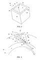
FIG. 2 is a perspective view of a flow control module including a flow control member in accordance with an exemplary embodiment; -
FIG. 3 is cross-sectional view of the flow control module ofFIG. 2 illustrating the flow control member in a first position; -
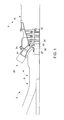
FIG. 4 is a cross-sectional view of the flow control module ofFIG. 2 illustrating the flow control member in a second position; and -
FIG. 5 is a cross-sectional view of a flow control module in accordance with another aspect of the exemplary embodiment. - The detailed description explains embodiments of the invention, together with advantages and features, by way of example with reference to the drawings.
- With reference to
FIG. 1 , a turbomachine constructed in accordance with an exemplary embodiment is indicated generally at 2.Turbomachine 2 includes acompressor portion 4 and aturbine portion 6.Compressor portion 4 includes a compressor housing 8 andturbine portion 6 includes aturbine housing 10.Compressor portion 4 is linked toturbine portion 6 through a common compressor/turbine shaft orrotor 16.Compressor portion 4 is also linked toturbine portion 6 through a plurality of circumferentially spaced combustor assemblies, one of which is indicated at 20.Combustor assembly 20 is fluidly connected toturbine portion 6 by atransition piece 24.Compressor portion 4 includes acompressor discharge plenum 27 that leads to adiffuser 30. - Compressed air flows from
compressor portion 4 intocompressor discharge plenum 27 passes throughdiffuser 30 and intocombustor assembly 20. The compressed air mixes with fuel to form a combustible mixture that is combusted to form hot gases. The hot gases flow throughtransition piece 24 along a hot gas path (not separately labeled) toward afirst stage 32 ofturbine portion 6. In addition to passing tocombustor assembly 20, a portion of the compressed air forms an air flow that is passed to awheel space 34 inturbine portion 6. In accordance with one aspect of the exemplary embodiment, the air flow represents cooling air passing intoturbine portion 6. - In accordance with an exemplary embodiment, the air flow passes from diffuser 30 through a
flow control module 40 intowheel space 34. As best shown inFIGs. 2-3 ,flow control module 40 includes aninlet 44 that leads to anoutlet 45 through aflow passage 47.Flow passage 47 includes first and secondopposing side walls opposing side walls First side wall 53 includes acurvilinear surface portion 59. Similarly,second side wall 54 includes acurvilinear surface portion 60. Third andfourth side walls linear surfaces Curvilinear surface portions diffuser 30 intowheel space 34 at a desired angle. More specifically,curvilinear surfaces wheel space 34 so as to pass tangentially acrossrotor 16. The air flow is guided in a direction corresponding to a direction of rotation ofrotor 16. By introducing the air flow in the direction of rotation, losses that would otherwise be associated with the coolingflow impacting rotor 16 at a substantially perpendicular angle are reduced. - When operating at peak or near peak output, air flow through
flow control module 40 is unimpeded so as to enhance cooling. However, during off-peak operation, the amount of air flow passing intowheel space 34 can be reduced. Reducing the amount of air flow passing intowheel space 34 leads to an increase in air flowing tocombustor assembly 20 which, in turn, leads to increased operational efficiency at off-peak operation. Accordingly,flow control module 40 includes aflow control member 80 that selectively, passively, extends intoflow passage 47 during off-peak operation such as shown inFIG. 4 . The term passively should be understood to mean thatflow control member 80 extends intoflow passage 47 based on a parameter of the air flow, not as a result of a particular control input. In accordance with the exemplary embodiment shown,flow control member 80 includes abi-metallic element 86 embedded infirst side wall 53.Bi-metallic element 86 includes afirst member 90 that is joined to asecond member 91. - When exposed to particular temperature ranges, first and
second members second members curvilinear surface portion 59 such as shown inFIG. 3 . However, when exposed to air flow during off-peak operations,first member 90 contracts at a rate that is distinct from a rate of contraction ofsecond member 91 resulting inflow control member 80 bulging or extending intoflow passage 47 such as shown inFIG. 4 . In this manner,flow control member 80 reduces an overall air flow passing towheel space 34. The reduction in air flow passing intowheel space 34 leads to an increase in compressor flow passing tocombustor assembly 20. The increase in compressor flow tocombustor assembly 20 leads to more complete combustion at off-peak operation so as to reduce emissions and increase efficiency. - Reference will now be made to
FIG. 5 in describing aflow control module 140 in accordance with another aspect of the exemplary embodiment.Flow control module 140 includes aninlet 144 that leads to anoutlet 145 through aflow passage 147.Flow passage 147 includes first and second opposingside walls third side wall 156 and a fourth side wall (not shown).First side wall 153 includes acurvilinear surface portion 159. Similarly,second side wall 154 includes acurvilinear surface portion 160.Third side wall 156 includes a substantially linear orsmooth surface 162. Similarly, the fourth side wall (not shown) likewise includes a substantially linear or smooth surface (also not shown). In a manner similar to that described above,curvilinear surface portions diffuser 30 intowheel space 34 at an angle. -
Flow control module 140 includes aflow control member 180 that selectively, passively, extends intoflow passage 147 during off-peak operation. In accordance with the exemplary aspect shown,flow control member 180 includes abi-metallic element 186 embedded inthird side wall 156. More specifically,flow control member 180 extends across or spansflow passage 147 and connects with first andsecond side walls Bi-metallic element 186 includes afirst member 190 that is joined to a second member (not shown). In a manner similar to that described above, bi-metallic element extends intoflow passage 147 during off-peak operation in order to reduce air flow passing intowheel space 34 and increase compressor flow passing tocombustor assembly 20 to enhance combustion and reduce emissions. - While the invention has been described in detail in connection with only a limited number of embodiments, it should be readily understood that the invention is not limited to such disclosed embodiments. Rather, the invention can be modified to incorporate any number of variations, alterations, substitutions or equivalent arrangements not heretofore described, but which are commensurate with the spirit and scope of the invention. Additionally, while various embodiments of the invention have been described, it is to be understood that aspects of the invention may include only some of the described embodiments. Accordingly, the invention is not to be seen as limited by the foregoing description, but is only limited by the scope of the appended claims.
Claims (13)
- A flow control module (40) for a turbomachine (2), the flow control module (40) comprising:an inlet (44) extending to an outlet (45) through a flow passage (47) having at least one side wall; anda flow control member (80) arranged within the control module (40), the flow control member (80) being secured to the at least one side wall between the inlet (44) and the outlet (45), the flow control member (80) being selectively passively activated to extend into the flow passage (47) to block cooling fluid passing through the flow control module (40).
- The flow control module (40) according to claim 1, wherein the at least one side wall includes first and second opposing side walls joined by third and fourth opposing side walls (53, 54, 56, 57), each of the first and second opposing side walls (53, 54) having a curvilinear surface (59) that guides cooling flow into the wheel space (34).
- The flow control module (40) according to claim 2, wherein the flow control member (80) is secured to one of the first and second opposing side walls.
- The flow control module (40) according to claim 2 or 3, wherein the third and fourth opposing side walls include a substantially linear surface (62).
- The flow control module (40) according to claim 4, wherein the flow control member (80) is secured to one of the third and fourth opposing side walls.
- The flow control module (40) according to claim 5, wherein the flow control member (80) extends across the one of the third and fourth side walls and connects with each of the first and second side walls (53, 54).
- The flow control module (40) according to any preceding claim, wherein the flow control member (80) is embedded in the at least one side wall.
- The flow control module (40) according to any preceding claim, wherein the flow control member (80) comprises a bi-metallic element (86).
- A turbomachine (2) comprising:a compressor portion (4) including a compressor discharge;a turbine portion (6) including a first stage (32) including wheel space portion (34), a shaft extending through the wheel space portion (34), a rotor mounted to the shaft, and at least one bucket mounted to the rotor; andthe flow control module of any of claims 1 to 8, arranged downstream from the compressor discharge and upstream from the first stage (32) of the turbine, (6) wherein the inlet (44) is fluidly connected to the compressor discharge and the outlet (45) is fluidly connected to the wheel space portion (34).
- A method of passively controlling an air flow passing from a compressor discharge (4) toward a turbine rotor (6), the method comprising:guiding an air flow from a compressor discharge (4) toward a flow control module (40) positioned upstream of a turbine wheel space (34);passing the air flow through a flow passage (47) extending through the flow control module (40); andcollapsing a first side wall (53) forming the flow passage (47) toward a second side wall (54) forming the flow passage (47) to constrict the flow control module (40) based on a characteristic of the air flow.
- The method of claim 10, further comprising: inducing a swirl to the air flow passing through the flow control module (40).
- The method of claim 10 or 11, wherein collapsing the first side wall (53) based on the characteristic of the air flow comprises collapsing the first side wall (53) based on a temperature of the air flow.
- The method of any of claims 10 to 12, wherein collapsing the first side wall (53) based on the characteristic of the air flow comprises contracting a portion of a bi-metallic strip (86) mounted in the flow passage (47).
Applications Claiming Priority (1)
| Application Number | Priority Date | Filing Date | Title |
|---|---|---|---|
| US13/220,008 US20130051976A1 (en) | 2011-08-29 | 2011-08-29 | Flow control module for a turbomachine |
Publications (1)
| Publication Number | Publication Date |
|---|---|
| EP2565426A1 true EP2565426A1 (en) | 2013-03-06 |
Family
ID=46682744
Family Applications (1)
| Application Number | Title | Priority Date | Filing Date |
|---|---|---|---|
| EP12180668A Withdrawn EP2565426A1 (en) | 2011-08-29 | 2012-08-16 | Cooling flow control module for a turbomachine |
Country Status (3)
| Country | Link |
|---|---|
| US (1) | US20130051976A1 (en) |
| EP (1) | EP2565426A1 (en) |
| CN (1) | CN103032108A (en) |
Families Citing this family (7)
| Publication number | Priority date | Publication date | Assignee | Title |
|---|---|---|---|---|
| US9435206B2 (en) | 2012-09-11 | 2016-09-06 | General Electric Company | Flow inducer for a gas turbine system |
| US10337411B2 (en) | 2015-12-30 | 2019-07-02 | General Electric Company | Auto thermal valve (ATV) for dual mode passive cooling flow modulation |
| US20170191373A1 (en) * | 2015-12-30 | 2017-07-06 | General Electric Company | Passive flow modulation of cooling flow into a cavity |
| US10544740B2 (en) | 2016-03-15 | 2020-01-28 | Rolls-Royce Corporation | Gas turbine engine with cooling air system |
| US10337739B2 (en) | 2016-08-16 | 2019-07-02 | General Electric Company | Combustion bypass passive valve system for a gas turbine |
| US10712007B2 (en) | 2017-01-27 | 2020-07-14 | General Electric Company | Pneumatically-actuated fuel nozzle air flow modulator |
| US10738712B2 (en) | 2017-01-27 | 2020-08-11 | General Electric Company | Pneumatically-actuated bypass valve |
Citations (4)
| Publication number | Priority date | Publication date | Assignee | Title |
|---|---|---|---|---|
| DE10225264A1 (en) * | 2001-09-17 | 2003-04-03 | Alstom Switzerland Ltd | Air-cooled turbine blade has cover band component at its point and extending vertically to blade longitudinal axis and provided with at least one through bore for cooling air |
| DE10347335A1 (en) * | 2003-10-11 | 2005-05-12 | Alstom Technology Ltd Baden | Gas turbine with honeycomb heat shield, provided with discontinuous air cooling device for honeycomb |
| EP1936468A1 (en) * | 2006-12-22 | 2008-06-25 | Siemens Aktiengesellschaft | Bi-metallic elements for adjusting a cooling channel |
| US20100080685A1 (en) * | 2008-09-30 | 2010-04-01 | General Electric Company | Method and Apparatus for Gas Turbine Engine Temperature Management |
Family Cites Families (5)
| Publication number | Priority date | Publication date | Assignee | Title |
|---|---|---|---|---|
| US2906494A (en) * | 1956-06-12 | 1959-09-29 | Daniel J Mccarty | Heat responsive means for blade cooling |
| US3575528A (en) * | 1968-10-28 | 1971-04-20 | Gen Motors Corp | Turbine rotor cooling |
| US4296599A (en) * | 1979-03-30 | 1981-10-27 | General Electric Company | Turbine cooling air modulation apparatus |
| EP1006263B1 (en) * | 1998-11-30 | 2004-01-07 | ALSTOM (Switzerland) Ltd | Vane cooling |
| GB2354290B (en) * | 1999-09-18 | 2004-02-25 | Rolls Royce Plc | A cooling air flow control device for a gas turbine engine |
-
2011
- 2011-08-29 US US13/220,008 patent/US20130051976A1/en not_active Abandoned
-
2012
- 2012-08-16 EP EP12180668A patent/EP2565426A1/en not_active Withdrawn
- 2012-08-29 CN CN2012103138461A patent/CN103032108A/en active Pending
Patent Citations (4)
| Publication number | Priority date | Publication date | Assignee | Title |
|---|---|---|---|---|
| DE10225264A1 (en) * | 2001-09-17 | 2003-04-03 | Alstom Switzerland Ltd | Air-cooled turbine blade has cover band component at its point and extending vertically to blade longitudinal axis and provided with at least one through bore for cooling air |
| DE10347335A1 (en) * | 2003-10-11 | 2005-05-12 | Alstom Technology Ltd Baden | Gas turbine with honeycomb heat shield, provided with discontinuous air cooling device for honeycomb |
| EP1936468A1 (en) * | 2006-12-22 | 2008-06-25 | Siemens Aktiengesellschaft | Bi-metallic elements for adjusting a cooling channel |
| US20100080685A1 (en) * | 2008-09-30 | 2010-04-01 | General Electric Company | Method and Apparatus for Gas Turbine Engine Temperature Management |
Also Published As
| Publication number | Publication date |
|---|---|
| CN103032108A (en) | 2013-04-10 |
| US20130051976A1 (en) | 2013-02-28 |
Similar Documents
| Publication | Publication Date | Title |
|---|---|---|
| EP2565426A1 (en) | Cooling flow control module for a turbomachine | |
| US9719372B2 (en) | Gas turbomachine including a counter-flow cooling system and method | |
| CN104061599B (en) | System for providing from fuel to burner | |
| CN110848730B (en) | Flow control wall for a heat engine | |
| US9134029B2 (en) | Radial midframe baffle for can-annular combustor arrangement having tangentially oriented combustor cans | |
| GB2442310A (en) | A turbine with clearance control system having louvers which reduce pressure losses | |
| US20160305281A1 (en) | Gas turbomachine including a counter-flow cooling system and method | |
| US9175565B2 (en) | Systems and apparatus relating to seals for turbine engines | |
| US20170370584A1 (en) | Combustor assembly for a turbine engine | |
| US20170350269A1 (en) | Passive clearance control sysem for gas turbomachine | |
| CN107869734B (en) | Advanced seal with reduced corner leakage | |
| US9127558B2 (en) | Turbomachine including horizontal joint heating and method of controlling tip clearance in a gas turbomachine | |
| CA2622013C (en) | Vane assembly with grommet | |
| EP2628899A2 (en) | Turbomachine flow improvement system | |
| US7363762B2 (en) | Gas turbine engines seal assembly and methods of assembling the same | |
| JP7130545B2 (en) | Gas turbine combustor, gas turbine, and method for manufacturing gas turbine combustor | |
| CN108870444B (en) | Combustor assemblies for gas turbine engines | |
| EP3832073A1 (en) | Improving heat transfer coefficients in a compressor case for improved tip clearance control system | |
| EP2484866A2 (en) | Cross-over purge flow system for a turbomachine wheel member | |
| EP2589878A2 (en) | Combustor assembly for a gas turbomachine | |
| AU2016217888B2 (en) | Operation method for improving partial load efficiency in a gas turbine and gas turbine with improved partial load efficiency | |
| EP2628898A2 (en) | Turbomachine Including Flow Improvement System | |
| EP2532834A2 (en) | Cooling flow control elements for turbomachine buckets and control method thereof | |
| CN106089309A (en) | The dovetail part switchback reduced for the blade/disk stress of the first order of turbine | |
| JP2014037831A (en) | Temperature gradient management arrangement for turbine system and method of managing temperature gradient of turbine system |
Legal Events
| Date | Code | Title | Description |
|---|---|---|---|
| PUAI | Public reference made under article 153(3) epc to a published international application that has entered the european phase |
Free format text: ORIGINAL CODE: 0009012 |
|
| AK | Designated contracting states |
Kind code of ref document: A1 Designated state(s): AL AT BE BG CH CY CZ DE DK EE ES FI FR GB GR HR HU IE IS IT LI LT LU LV MC MK MT NL NO PL PT RO RS SE SI SK SM TR |
|
| AX | Request for extension of the european patent |
Extension state: BA ME |
|
| 17P | Request for examination filed |
Effective date: 20130906 |
|
| RBV | Designated contracting states (corrected) |
Designated state(s): AL AT BE BG CH CY CZ DE DK EE ES FI FR GB GR HR HU IE IS IT LI LT LU LV MC MK MT NL NO PL PT RO RS SE SI SK SM TR |
|
| STAA | Information on the status of an ep patent application or granted ep patent |
Free format text: STATUS: THE APPLICATION IS DEEMED TO BE WITHDRAWN |
|
| 18D | Application deemed to be withdrawn |
Effective date: 20150301 |