EP2565385A2 - Method and apparatus for segregated oil supply and scavenge in a gas turbine engine - Google Patents
Method and apparatus for segregated oil supply and scavenge in a gas turbine engine Download PDFInfo
- Publication number
- EP2565385A2 EP2565385A2 EP12182821A EP12182821A EP2565385A2 EP 2565385 A2 EP2565385 A2 EP 2565385A2 EP 12182821 A EP12182821 A EP 12182821A EP 12182821 A EP12182821 A EP 12182821A EP 2565385 A2 EP2565385 A2 EP 2565385A2
- Authority
- EP
- European Patent Office
- Prior art keywords
- frame
- scavenge
- oil
- aft
- bearing
- Prior art date
- Legal status (The legal status is an assumption and is not a legal conclusion. Google has not performed a legal analysis and makes no representation as to the accuracy of the status listed.)
- Withdrawn
Links
- 238000000034 method Methods 0.000 title claims description 11
- 239000003595 mist Substances 0.000 claims abstract description 12
- 238000005096 rolling process Methods 0.000 claims abstract description 11
- 238000007599 discharging Methods 0.000 claims description 2
- 239000010705 motor oil Substances 0.000 abstract 1
- 239000003921 oil Substances 0.000 abstract 1
- 238000001816 cooling Methods 0.000 description 3
- 238000005461 lubrication Methods 0.000 description 3
- 239000012530 fluid Substances 0.000 description 2
- 239000000463 material Substances 0.000 description 2
- 238000007789 sealing Methods 0.000 description 2
- KXGFMDJXCMQABM-UHFFFAOYSA-N 2-methoxy-6-methylphenol Chemical compound [CH]OC1=CC=CC([CH])=C1O KXGFMDJXCMQABM-UHFFFAOYSA-N 0.000 description 1
- OKTJSMMVPCPJKN-UHFFFAOYSA-N Carbon Chemical compound [C] OKTJSMMVPCPJKN-UHFFFAOYSA-N 0.000 description 1
- 229910052799 carbon Inorganic materials 0.000 description 1
- 238000005516 engineering process Methods 0.000 description 1
- 230000003993 interaction Effects 0.000 description 1
- 238000012986 modification Methods 0.000 description 1
- 230000004048 modification Effects 0.000 description 1
- 239000005011 phenolic resin Substances 0.000 description 1
- 229920001568 phenolic resin Polymers 0.000 description 1
- 230000003068 static effect Effects 0.000 description 1
- 238000009423 ventilation Methods 0.000 description 1
Images

Classifications
-
- F—MECHANICAL ENGINEERING; LIGHTING; HEATING; WEAPONS; BLASTING
- F01—MACHINES OR ENGINES IN GENERAL; ENGINE PLANTS IN GENERAL; STEAM ENGINES
- F01D—NON-POSITIVE DISPLACEMENT MACHINES OR ENGINES, e.g. STEAM TURBINES
- F01D9/00—Stators
- F01D9/06—Fluid supply conduits to nozzles or the like
- F01D9/065—Fluid supply or removal conduits traversing the working fluid flow, e.g. for lubrication-, cooling-, or sealing fluids
-
- F—MECHANICAL ENGINEERING; LIGHTING; HEATING; WEAPONS; BLASTING
- F01—MACHINES OR ENGINES IN GENERAL; ENGINE PLANTS IN GENERAL; STEAM ENGINES
- F01D—NON-POSITIVE DISPLACEMENT MACHINES OR ENGINES, e.g. STEAM TURBINES
- F01D25/00—Component parts, details, or accessories, not provided for in, or of interest apart from, other groups
- F01D25/16—Arrangement of bearings; Supporting or mounting bearings in casings
- F01D25/162—Bearing supports
-
- F—MECHANICAL ENGINEERING; LIGHTING; HEATING; WEAPONS; BLASTING
- F01—MACHINES OR ENGINES IN GENERAL; ENGINE PLANTS IN GENERAL; STEAM ENGINES
- F01D—NON-POSITIVE DISPLACEMENT MACHINES OR ENGINES, e.g. STEAM TURBINES
- F01D25/00—Component parts, details, or accessories, not provided for in, or of interest apart from, other groups
- F01D25/18—Lubricating arrangements
-
- F—MECHANICAL ENGINEERING; LIGHTING; HEATING; WEAPONS; BLASTING
- F05—INDEXING SCHEMES RELATING TO ENGINES OR PUMPS IN VARIOUS SUBCLASSES OF CLASSES F01-F04
- F05D—INDEXING SCHEME FOR ASPECTS RELATING TO NON-POSITIVE-DISPLACEMENT MACHINES OR ENGINES, GAS-TURBINES OR JET-PROPULSION PLANTS
- F05D2260/00—Function
- F05D2260/60—Fluid transfer
- F05D2260/609—Deoiling or demisting
-
- F—MECHANICAL ENGINEERING; LIGHTING; HEATING; WEAPONS; BLASTING
- F05—INDEXING SCHEMES RELATING TO ENGINES OR PUMPS IN VARIOUS SUBCLASSES OF CLASSES F01-F04
- F05D—INDEXING SCHEME FOR ASPECTS RELATING TO NON-POSITIVE-DISPLACEMENT MACHINES OR ENGINES, GAS-TURBINES OR JET-PROPULSION PLANTS
- F05D2260/00—Function
- F05D2260/98—Lubrication
Definitions
- This invention relates generally to gas turbine engine bearing sumps and more particularly to fluid flow provisions in bearing sumps.
- a gas turbine engine includes one or more shafts which are mounted for rotation in several bearings, usually of the rolling-element type.
- the bearings are enclosed in enclosures called “sumps” which are pressurized and provided with an oil flow for lubrication and cooling.
- sumps enclosures
- oil flow for lubrication and cooling.
- one of the boundaries of the sump will be a dynamic seal between a rotating component of the engine and the engine's stationary structure.
- Various tubes connectively referred to as “service tubes”, are used to supply oil to the sump, to drain spent oil from the sump, to pressurize the sump with air, and to vent air from the sump.
- the bearings and sumps are mounted within a casing of the engine using stationary structural members commonly called frames, usually having a central hub connected to an annular outer rim with a plurality of radial struts.
- the above-mentioned service tubes frequently are routed through the struts.
- Some gas turbine engines incorporate a type of frame called a “turbine vane frame” or “TVF” instead of a traditional “turbine center frame” or “TCF”.
- a TVF has fewer struts than a TCF and those struts are usually thinner in cross-section than a comparable TCF. Utilizing a TVF rather than a TCF can enhance the engine's performance and reduce the overall engine weight.
- the thinner and fewer struts of a TVF while providing several advantages, also challenge the ability to route large oil supply, scavenge, drain and ventilation tubes to bearing sumps.
- an oil supply and scavenge apparatus for a gas turbine engine includes: a stationary first frame comprising a first hub and a first outer ring interconnected by an array of radially-extending hollow first struts; a forward wet cavity defined radially inboard of the first frame, having a first rolling element bearing disposed therein; a supply line extending from the first outer ring through one of the first struts and communicating with the forward wet cavity, the supply line adapted to discharge oil to the forward wet cavity; a stationary second frame comprising a second hub and a second outer ring interconnected by an array of radially-extending hollow second struts, the second frame disposed aft of the first frame; and a scavenge path communicating with the forward wet cavity and adapted to remove oil-air mist from the forward wet cavity, the scavenge path defined at least in part by the second frame.
- a method of supplying oil to a bearing in a gas turbine includes: flowing oil through a supply line that extends radially inward through a hollow strut of a stationary first frame, where the first frame comprises a first hub and a first outer ring interconnected by an array of radially-extending hollow first struts, and discharging the oil into a forward wet cavity disposed radially inboard of the first frame which encloses a first rolling element bearing; using the oil to lubricate the first rolling element bearing, whereby an oil-air mist is generated; and extracting the oil-air mist through a scavenge path which extends through a stationary second frame that comprises a hub and an outer ring interconnected by an array of radially-extending hollow struts, the second frame disposed aft of the first frame and the rolling element bearing.
- FIG. 1 depicts a schematic view of a gas turbine engine 10.
- the engine 10 has a longitudinal axis 11 and includes a fan 12, a low pressure compressor or “booster” 14 and a low pressure turbine (“LPT”) 16 collectively referred to as a "low pressure system”.
- the LPT 16 drives the fan 12 and booster 14 through an inner shaft 18, also referred to as an "LP shaft”.
- the engine 10 also includes a high pressure compressor ("HPC") 20, a combustor 22, and a high pressure turbine (“HPT”) 24, collectively referred to as a "gas generator” or “core”.
- HPT 24 drives the HPC 20 through an outer shaft 26, also referred to as an "HP shaft".
- the high and low pressure systems are operable in a known manner to generate a primary or core flow as well as a fan flow or bypass flow. While the illustrated engine 10 is a high-bypass turbofan engine, the principles described herein are equally applicable to turboprop, turbojet, and turboshaft engines, as well as turbine engines used for other vehicles or in stationary applications.
- the inner and outer shafts 18 and 26 are mounted for rotation in several rolling-element bearings.
- the bearings are located in enclosed portions of the engine 10 referred to as "sumps".
- One such sump is noted at 28 in FIG. 1 .
- FIG. 2 shows an aft end of the engine 10 in and around the area of the sump 28 in more detail.
- the aft end of the outer shaft 26 is carried by a first bearing 32 which is this example is a roller bearing.
- the outer race 34 of the bearing 32 is attached to a static annular frame member of the engine 10.
- the frame member is a turbine vane frame or TVF 36.
- the TVF 36 includes a hollow annular hub 38 with a box-like cross-sectional shape, an array of hollow, airfoil-shaped struts 40, and an annular outer ring 42.
- a forward frame arm 44 extends in a generally radial direction inward from the hub 38.
- a stationary forward seal arm 46 extends axially aft from the forward frame arm 44.
- the distal end of the forward seal arm 46 includes a number of annular seal teeth 48 which extend radially outwards.
- the aft end of the inner shaft 18 extends aft of the outer shaft 26 and is mounted for rotation in a turbine rear frame (TRF) 50 of the engine by a second rolling element bearing 52, which in this example is a roller bearing.
- the inner shaft 18 has a disk 54 extending generally radially outward from it. The disk 54 extends between the inner shaft 18 and the LPT 16 (see FIG. 1 ) and transmits torque between the LPT 16 and the inner shaft 18.
- a forward rotating seal 56 extends axially forward from the disk 54.
- the forward rotating seal 54 has a generally annular body.
- the forward end of the forward rotating seal 56 includes a radially inward-facing seal pocket 58 which may contain a compliant seal material of a known type such as abradable phenolic resin, a metallic honeycomb structure, a carbon seal, or a brush seal.
- the forward end of the forward rotating seal 56 overlaps the aft end of the forward seal arm 46 in the axial direction, and the seal pocket 58 is aligned with the seal teeth 48 in the axial direction, so that they cooperatively form a rotating, non-contact seal interface.
- the structure of the sealing components could be reversed; e.g. the forward rotating seal 56 could include radially-extending seal teeth while the forward seal arm 46 could include a seal pocket.
- the outer shaft 26, the inner shaft 18, the disk 54, the forward seal arm 46, and the forward rotating seal 56 define a forward "wet” cavity or “oiled” cavity 60.
- the term “wet” or “oiled” when describing a cavity is used as a term to identify the enclosed space regardless of whether it actually contains oil or another fluid in a given operational condition.
- the radially adjacent forward dry cavity 61 is pressurized in operation, tending to create a positive pressure flow from dry to wet (i.e. a positive pressure gradient).
- Pressurized oil flow is provided to the first bearing 32 through one or more supply lines 62.
- supply lines 62 typically several supply lines 62 would be arranged in an array around the circumference of the engine 10. Only one supply line 62 is shown in FIG. 2 .
- the supply line 62 has a outer end 64 disposed outside the outer ring 42 of the TVF 36. This is coupled to an oil supply and circulation system of a known type (not shown).
- the supply line 62 passes through the hollow interior of one of the struts 40 and through the hub 38 and terminates in a nozzle 66 disposed within the forward wet cavity 60 near the first bearing 32.
- the nozzle 66 may discharge directly at the first bearing 32 or it may discharge oil generally into the area near the first bearing 32, with holes or orifices used to further route the oil to the first bearing 32.
- the supply line 62 is the smallest diameter of any of the service tubes, for example having an outside diameter of about 6.3 mm (0.25in.) to about 12.7 mm (0.5in.), and is readily accommodated within the struts 40.
- the TRF 50 (see FIG. 1 ) is disposed aft of the LPT 16.
- the TRF 50 includes a hollow annular hub 68 with a box-like cross-sectional shape, an array of hollow struts 70, and an annular outer ring 72.
- An annular aft frame arm 74 extends radially inward and axially forward in a generally radial direction inward from the hub 68.
- the outer race 76 of the second bearing 52 is attached to the distal end of the aft frame arm 74.
- a stationary aft seal arm 78 extends axially forward from the aft frame arm 74.
- the aft seal arm 78 includes a radially inward-facing seal pocket 80 which may contain a compliant seal material of a known type as described above.
- An aft rotating seal 82 extends axially aft from the disk 54.
- the aft rotating seal 82 has a generally cylindrical body.
- the aft end of the aft rotating seal 82 includes a number of annular seal teeth 84 which extend radially outwards.
- the aft end of the aft rotating seal 82 overlaps the forward end of the aft seal arm 78 in the axial direction, and the seal pocket 80 is aligned with the seal teeth 84 in the axial direction, so that they cooperatively form a rotating, non-contact seal interface. It is noted that the structure of the sealing components could be reversed as described above.
- the inner shaft 18, the disk 54, the aft rotating seal 82, the aft seal arm 78 and the aft frame arm 74 define an aft "wet" cavity or "oiled” cavity 86.
- the radially adjacent aft dry cavity 87 is pressurized in operation, tending to create a positive pressure flow from dry to wet (i.e. a positive pressure gradient).
- the first bearing 32 is supplied with oil from the nozzle 66 to provide lubrication and cooling
- the second bearing 52 is supplied with oil from another nozzle 88 to provide lubrication and cooling.
- the interaction of the oil supply and the bearings 32 and 52 creates a mist of oil within the wet cavities 60 and 86.
- a scavenge flow path passing axially aft and at least partially through the TRF 50 is provided to remove this oil mist from the forward and aft wet cavities 60 and 86.
- one or more transfer ports 90 pass through the disk 54 so that the forward and aft wet cavities 60 and 86 can communicate with each other.
- a scavenge port 92 is formed in the aft seal arm 78 and communicates with a scavenge plenum 94.
- a scavenge tube 96 communicates with the scavenge plenum.
- the scavenge tube 96 is coupled to the scavenge portion of an oil supply and circulation system as described above. The size of the scavenge tube in a typical application would be significantly greater than the size of the supply tube 62 described above.
- scavenge service tubes air flow to pressurize the dry cavities 61 and 87, and vent air flow from them is provided through a path passing through the TRF 50. Pressurization air flow could also be provided by bores or flow circuits inside or between the shafts 18 or 26 (not shown). Thus, only the supply tubes 62 need to pass through the TVF 36.
- the oil supply and scavenge apparatus described above has several advantages over prior art designs. It may be used in any high performance engine structure requiring thin struts to enhance engine performance, or any engine design in which it is difficult to route large service tubes through small struts.
- the invention accommodates TVF technology, which leads to better engine performance and a lighter engine. As opposed to other solutions, it prevents life and weight impacts to the inner shaft 18.
Landscapes
- Engineering & Computer Science (AREA)
- Mechanical Engineering (AREA)
- General Engineering & Computer Science (AREA)
- Physics & Mathematics (AREA)
- Fluid Mechanics (AREA)
- Rolling Contact Bearings (AREA)
Abstract
Description
- This invention relates generally to gas turbine engine bearing sumps and more particularly to fluid flow provisions in bearing sumps.
- A gas turbine engine includes one or more shafts which are mounted for rotation in several bearings, usually of the rolling-element type. The bearings are enclosed in enclosures called "sumps" which are pressurized and provided with an oil flow for lubrication and cooling. In most cases one of the boundaries of the sump will be a dynamic seal between a rotating component of the engine and the engine's stationary structure. Various tubes, connectively referred to as "service tubes", are used to supply oil to the sump, to drain spent oil from the sump, to pressurize the sump with air, and to vent air from the sump.
- The bearings and sumps are mounted within a casing of the engine using stationary structural members commonly called frames, usually having a central hub connected to an annular outer rim with a plurality of radial struts. The above-mentioned service tubes frequently are routed through the struts. Some gas turbine engines incorporate a type of frame called a "turbine vane frame" or "TVF" instead of a traditional "turbine center frame" or "TCF". A TVF has fewer struts than a TCF and those struts are usually thinner in cross-section than a comparable TCF. Utilizing a TVF rather than a TCF can enhance the engine's performance and reduce the overall engine weight.
- The thinner and fewer struts of a TVF, while providing several advantages, also challenge the ability to route large oil supply, scavenge, drain and ventilation tubes to bearing sumps.
- Accordingly, there is a need for a configuration for routing tubes within a gas turbine engine having limited frame strut area.
- This need is addressed by the present invention, which provides a gas turbine engine in which some of the tubes needed to service a sump are routed through a turbine vane frame while the majority of the tubes are routed through a different path.
- According to one aspect of the invention, an oil supply and scavenge apparatus for a gas turbine engine includes: a stationary first frame comprising a first hub and a first outer ring interconnected by an array of radially-extending hollow first struts; a forward wet cavity defined radially inboard of the first frame, having a first rolling element bearing disposed therein; a supply line extending from the first outer ring through one of the first struts and communicating with the forward wet cavity, the supply line adapted to discharge oil to the forward wet cavity; a stationary second frame comprising a second hub and a second outer ring interconnected by an array of radially-extending hollow second struts, the second frame disposed aft of the first frame; and a scavenge path communicating with the forward wet cavity and adapted to remove oil-air mist from the forward wet cavity, the scavenge path defined at least in part by the second frame.
- According to another aspect of the invention, a method of supplying oil to a bearing in a gas turbine includes: flowing oil through a supply line that extends radially inward through a hollow strut of a stationary first frame, where the first frame comprises a first hub and a first outer ring interconnected by an array of radially-extending hollow first struts, and discharging the oil into a forward wet cavity disposed radially inboard of the first frame which encloses a first rolling element bearing; using the oil to lubricate the first rolling element bearing, whereby an oil-air mist is generated; and extracting the oil-air mist through a scavenge path which extends through a stationary second frame that comprises a hub and an outer ring interconnected by an array of radially-extending hollow struts, the second frame disposed aft of the first frame and the rolling element bearing.
- The invention may be best understood by reference to the following description taken in conjunction with the accompanying drawing figures in which:
-
FIG. 1 is a half-sectional view of a gas turbine engine incorporating a rotating oil seal constructed according to an aspect of the present invention; and -
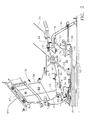
FIG. 2 is an enlarged view of an aft portion of the gas turbine engine ofFIG. 1 . - Referring to the drawings wherein identical reference numerals denote the same elements throughout the various views,
FIG. 1 depicts a schematic view of agas turbine engine 10. Theengine 10 has alongitudinal axis 11 and includes afan 12, a low pressure compressor or "booster" 14 and a low pressure turbine ("LPT") 16 collectively referred to as a "low pressure system". TheLPT 16 drives thefan 12 andbooster 14 through aninner shaft 18, also referred to as an "LP shaft". Theengine 10 also includes a high pressure compressor ("HPC") 20, acombustor 22, and a high pressure turbine ("HPT") 24, collectively referred to as a "gas generator" or "core". The HPT 24 drives the HPC 20 through anouter shaft 26, also referred to as an "HP shaft". Together, the high and low pressure systems are operable in a known manner to generate a primary or core flow as well as a fan flow or bypass flow. While the illustratedengine 10 is a high-bypass turbofan engine, the principles described herein are equally applicable to turboprop, turbojet, and turboshaft engines, as well as turbine engines used for other vehicles or in stationary applications. - The inner and
outer shafts engine 10 referred to as "sumps". One such sump is noted at 28 inFIG. 1 . -
FIG. 2 shows an aft end of theengine 10 in and around the area of thesump 28 in more detail. The aft end of theouter shaft 26 is carried by a first bearing 32 which is this example is a roller bearing. Theouter race 34 of the bearing 32 is attached to a static annular frame member of theengine 10. The frame member is a turbine vane frame or TVF 36. The TVF 36 includes a hollowannular hub 38 with a box-like cross-sectional shape, an array of hollow, airfoil-shaped struts 40, and an annularouter ring 42. Aforward frame arm 44 extends in a generally radial direction inward from thehub 38. A stationaryforward seal arm 46 extends axially aft from theforward frame arm 44. The distal end of theforward seal arm 46 includes a number ofannular seal teeth 48 which extend radially outwards. - The aft end of the
inner shaft 18 extends aft of theouter shaft 26 and is mounted for rotation in a turbine rear frame (TRF) 50 of the engine by a second rolling element bearing 52, which in this example is a roller bearing. Theinner shaft 18 has adisk 54 extending generally radially outward from it. Thedisk 54 extends between theinner shaft 18 and the LPT 16 (seeFIG. 1 ) and transmits torque between theLPT 16 and theinner shaft 18. - A forward rotating
seal 56 extends axially forward from thedisk 54. The forward rotatingseal 54 has a generally annular body. The forward end of the forward rotatingseal 56 includes a radially inward-facingseal pocket 58 which may contain a compliant seal material of a known type such as abradable phenolic resin, a metallic honeycomb structure, a carbon seal, or a brush seal. - The forward end of the forward rotating
seal 56 overlaps the aft end of theforward seal arm 46 in the axial direction, and theseal pocket 58 is aligned with theseal teeth 48 in the axial direction, so that they cooperatively form a rotating, non-contact seal interface. It is noted that the structure of the sealing components could be reversed; e.g. the forward rotatingseal 56 could include radially-extending seal teeth while theforward seal arm 46 could include a seal pocket. - Collectively, the
outer shaft 26, theinner shaft 18, thedisk 54, theforward seal arm 46, and the forward rotatingseal 56 define a forward "wet" cavity or "oiled"cavity 60. As used herein, the term "wet" or "oiled" when describing a cavity is used as a term to identify the enclosed space regardless of whether it actually contains oil or another fluid in a given operational condition. The radially adjacent forwarddry cavity 61 is pressurized in operation, tending to create a positive pressure flow from dry to wet (i.e. a positive pressure gradient). - Pressurized oil flow is provided to the first bearing 32 through one or
more supply lines 62. Typicallyseveral supply lines 62 would be arranged in an array around the circumference of theengine 10. Only onesupply line 62 is shown inFIG. 2 . Thesupply line 62 has aouter end 64 disposed outside theouter ring 42 of the TVF 36. This is coupled to an oil supply and circulation system of a known type (not shown). Thesupply line 62 passes through the hollow interior of one of the struts 40 and through thehub 38 and terminates in anozzle 66 disposed within the forwardwet cavity 60 near the first bearing 32. Thenozzle 66 may discharge directly at the first bearing 32 or it may discharge oil generally into the area near the first bearing 32, with holes or orifices used to further route the oil to the first bearing 32. Thesupply line 62 is the smallest diameter of any of the service tubes, for example having an outside diameter of about 6.3 mm (0.25in.) to about 12.7 mm (0.5in.), and is readily accommodated within the struts 40. - The TRF 50 (see
FIG. 1 ) is disposed aft of theLPT 16. The TRF 50 includes a hollowannular hub 68 with a box-like cross-sectional shape, an array ofhollow struts 70, and an annularouter ring 72. An annularaft frame arm 74 extends radially inward and axially forward in a generally radial direction inward from thehub 68. Referring back toFIG. 2 , theouter race 76 of the second bearing 52 is attached to the distal end of theaft frame arm 74. A stationaryaft seal arm 78 extends axially forward from theaft frame arm 74. Theaft seal arm 78 includes a radially inward-facingseal pocket 80 which may contain a compliant seal material of a known type as described above. - An aft
rotating seal 82 extends axially aft from thedisk 54. The aftrotating seal 82 has a generally cylindrical body. The aft end of the aftrotating seal 82 includes a number ofannular seal teeth 84 which extend radially outwards. - The aft end of the aft
rotating seal 82 overlaps the forward end of theaft seal arm 78 in the axial direction, and theseal pocket 80 is aligned with theseal teeth 84 in the axial direction, so that they cooperatively form a rotating, non-contact seal interface. It is noted that the structure of the sealing components could be reversed as described above. - Collectively, the
inner shaft 18, thedisk 54, the aftrotating seal 82, theaft seal arm 78 and theaft frame arm 74 define an aft "wet" cavity or "oiled"cavity 86. The radially adjacent aftdry cavity 87 is pressurized in operation, tending to create a positive pressure flow from dry to wet (i.e. a positive pressure gradient). - In operation, the first bearing 32 is supplied with oil from the
nozzle 66 to provide lubrication and cooling, and thesecond bearing 52 is supplied with oil from anothernozzle 88 to provide lubrication and cooling. The interaction of the oil supply and thebearings 32 and 52 creates a mist of oil within thewet cavities TRF 50 is provided to remove this oil mist from the forward and aftwet cavities - To accommodate the scavenge flow, one or
more transfer ports 90 pass through thedisk 54 so that the forward and aftwet cavities scavenge port 92 is formed in theaft seal arm 78 and communicates with ascavenge plenum 94. Ascavenge tube 96 communicates with the scavenge plenum. Thescavenge tube 96 is coupled to the scavenge portion of an oil supply and circulation system as described above. The size of the scavenge tube in a typical application would be significantly greater than the size of thesupply tube 62 described above. - In addition the scavenge service tubes, air flow to pressurize the
dry cavities TRF 50. Pressurization air flow could also be provided by bores or flow circuits inside or between theshafts 18 or 26 (not shown). Thus, only thesupply tubes 62 need to pass through theTVF 36. - The oil supply and scavenge apparatus described above has several advantages over prior art designs. It may be used in any high performance engine structure requiring thin struts to enhance engine performance, or any engine design in which it is difficult to route large service tubes through small struts. The invention accommodates TVF technology, which leads to better engine performance and a lighter engine. As opposed to other solutions, it prevents life and weight impacts to the
inner shaft 18. - The foregoing has described an oil supply and scavenge apparatus and method for a gas turbine engine. While specific embodiments of the present invention have been described, it will be apparent to those skilled in the art that various modifications thereto can be made without departing from the spirit and scope of the invention. Accordingly, the foregoing description of the preferred embodiment of the invention and the best mode for practicing the invention are provided for the purpose of illustration only and not for the purpose of limitation, the invention being defined by the claims.
Claims (16)
- An oil supply and scavenge apparatus for a gas turbine engine (10), comprising:a stationary first frame (36) comprising a first hub (38) and a first outer ring (42) interconnected by an array of radially-extending hollow first struts (40);a forward wet cavity (60) defined radially inboard of the first frame, having a first rolling element bearing (32) disposed therein;a supply line (62) extending from the first outer ring through one of the first struts and communicating with the forward wet cavity, the supply line adapted to discharge oil to the forward wet cavity;a stationary second frame (50) comprising a second hub (68) and a second outer ring (72) interconnected by an array of radially-extending hollow second struts (70), the second frame disposed aft of the first frame; anda scavenge path communicating with the forward wet cavity (60) and adapted to remove oil-air mist from the forward wet cavity, the scavenge path defined at least in part by the second frame (50).
- The apparatus of claim 1, wherein the second frame (50) includes an annular rear frame arm (74) extending radially inward from the second hub (68), and the scavenge path passes through the rear frame arm.
- The apparatus of either of claim 1 or 2, wherein the second frame (50) defines a scavenge plenum (94) communicating with the scavenge path.
- The apparatus of claim 3, wherein a scavenge tube (96) communicates with the scavenge plenum (94) and an exterior of the second frame (50).
- The apparatus of any preceding claim, wherein the first bearing (32) supports a hollow outer shaft (26) for rotation relative to the first frame (36).
- The apparatus of claim 5, wherein an inner shaft (18) is disposed concentrically within the outer shaft (26) and is supported for rotation relative to the second frame (50) by a rolling-element second bearing (52).
- The apparatus of claim 6, wherein the second bearing (52) is disposed inside an aft wet cavity (86) defined axially aft of the forward wet cavity (60).
- The apparatus of claim 7, wherein the inner shaft (18) includes an annular disk (54) extending radially outward therefrom, the disk defining a boundary between the forward and aft wet cavities (60, 86).
- The apparatus of claim 8, wherein at least one transfer port (90) extends through the disk (54) so as to interconnect the forward and aft wet cavities (60, 86).
- A method of supplying oil to a bearing in a gas turbine (10), comprising:flowing oil through a supply line (62) that extends radially inward through a hollow strut (40) of a stationary first frame (36), where the first frame comprises a first hub (38) and a first outer ring (42) interconnected by an array of radially-extending hollow first struts, and discharging the oil into a forward wet cavity (60) disposed radially inboard of the first frame which encloses a first rolling element bearing (32);using the oil to lubricate the first rolling element bearing, whereby an oil-air mist is generated; andextracting the oil-air mist through a scavenge path which extends through a stationary second frame (50) that comprises a second hub (68) and a second outer ring (72) interconnected by an array of radially-extending second hollow struts (70), the second frame disposed aft of the first frame and the first rolling element bearing.
- The method of claim 10, wherein the second frame (50) includes an annular rear frame arm (74) extending radially inward from the second hub (68), and the scavenge path passes through the rear frame arm.
- The method of either of claim 10 or 11, wherein the second frame(50) defines a scavenge plenum (94) communicating with the scavenge path.
- The method of claim 12, wherein a scavenge tube (96) communicates with the scavenge plenum (94) and an exterior of the second frame (50).
- The method of any of claims 10 to 13, wherein the first bearing (32) supports a hollow outer shaft (26) for rotation relative to the first frame (36).
- The method of claim 14 wherein an inner shaft (18) is disposed concentrically within the outer shaft (26) and is supported for rotation relative to the second frame (50) by a rolling-element second bearing (52), and the second bearing is disposed inside an aft wet cavity (86) defined axially aft of the forward wet cavity (60), the method further comprising:using a second flow of oil to lubricate the second rolling element bearing (52), whereby a second oil-air mist is generated; andextracting the second oil-air mist through the scavenge path.
- The method of claim 15, wherein the inner shaft (18) includes an annular disk (54) extending radially outwardly therefrom, the disk defining a boundary between the forward and aft wet cavities (60, 86), wherein the oil-air mist is extracted from the forward wet cavity (60) through at least one transfer port (90) extending through the disk (54), and then through the aft wet cavity (86).
Applications Claiming Priority (1)
| Application Number | Priority Date | Filing Date | Title |
|---|---|---|---|
| US13/225,510 US8904746B2 (en) | 2011-09-05 | 2011-09-05 | Method and apparatus for segregated oil supply and scavenge in a gas turbine engine |
Publications (2)
| Publication Number | Publication Date |
|---|---|
| EP2565385A2 true EP2565385A2 (en) | 2013-03-06 |
| EP2565385A3 EP2565385A3 (en) | 2018-03-21 |
Family
ID=46758640
Family Applications (1)
| Application Number | Title | Priority Date | Filing Date |
|---|---|---|---|
| EP12182821.4A Withdrawn EP2565385A3 (en) | 2011-09-05 | 2012-09-03 | Method and apparatus for segregated oil supply and scavenge in a gas turbine engine |
Country Status (3)
| Country | Link |
|---|---|
| US (1) | US8904746B2 (en) |
| EP (1) | EP2565385A3 (en) |
| CA (1) | CA2788264A1 (en) |
Cited By (1)
| Publication number | Priority date | Publication date | Assignee | Title |
|---|---|---|---|---|
| EP3124752A1 (en) * | 2015-07-27 | 2017-02-01 | General Electric Company | Gas turbine engine frame assembly |
Families Citing this family (16)
| Publication number | Priority date | Publication date | Assignee | Title |
|---|---|---|---|---|
| US9644495B2 (en) | 2013-08-20 | 2017-05-09 | Honeywell International Inc. | Thermal isolating service tubes and assemblies thereof for gas turbine engines |
| US10458339B2 (en) | 2016-01-12 | 2019-10-29 | United Technologies Corporation | Gas turbine engine case flow blocking covers |
| US10100875B2 (en) | 2016-07-26 | 2018-10-16 | General Electric Company | Roller bearing and systems including such |
| US10030708B2 (en) | 2016-07-29 | 2018-07-24 | General Electric Company | Roller bearing cage for use in a gearbox |
| US10138940B2 (en) | 2016-08-09 | 2018-11-27 | General Electric Company | Roller bearing cage for use in a gearbox |
| US10400678B2 (en) | 2017-01-03 | 2019-09-03 | General Electric Company | Apparatus and system for light-weight, flexible double-helical gear |
| US10508731B2 (en) | 2017-01-05 | 2019-12-17 | General Electric Company | Apparatus and method for managing pinch loads on a gear |
| US10247298B2 (en) | 2017-01-10 | 2019-04-02 | General Electric Company | Resilient bearing pin and gear assemblies including resilient bearing pins |
| US10228024B2 (en) | 2017-01-10 | 2019-03-12 | General Electric Company | Reduced-weight bearing pins and methods of manufacturing such bearing pins |
| US10247297B2 (en) | 2017-01-18 | 2019-04-02 | General Electric Company | Apparatus for a gearbox with multiple scavenge ports |
| US10408304B2 (en) | 2017-02-07 | 2019-09-10 | General Electric Company | Gears having reduced roller element stresses and methods of manufacturing such gears |
| US10451113B2 (en) | 2017-05-18 | 2019-10-22 | General Electric Company | Bearing cages for roller bearing assemblies |
| US10260563B2 (en) | 2017-05-18 | 2019-04-16 | General Electric Company | Bearing cages for roller bearing assemblies |
| US10385961B2 (en) | 2017-10-25 | 2019-08-20 | General Electric Company | Planetary gear system |
| US11970279B2 (en) | 2020-02-21 | 2024-04-30 | General Electric Company | Control system and methods of controlling an engine-mounting link system |
| US11939070B2 (en) | 2020-02-21 | 2024-03-26 | General Electric Company | Engine-mounting links that have an adjustable inclination angle |
Family Cites Families (9)
| Publication number | Priority date | Publication date | Assignee | Title |
|---|---|---|---|---|
| GB736017A (en) * | 1952-08-05 | 1955-08-31 | Bristol Aeroplane Co Ltd | Improvements in or relating to gas turbine engines |
| US3528241A (en) * | 1969-02-24 | 1970-09-15 | Gen Electric | Gas turbine engine lubricant sump vent and circulating system |
| US6470666B1 (en) | 2001-04-30 | 2002-10-29 | General Electric Company | Methods and systems for preventing gas turbine engine lube oil leakage |
| US7699530B2 (en) * | 2006-09-28 | 2010-04-20 | Pratt & Whitney Canada Corp. | Oil scavenge system for gas turbine engine bearing cavity |
| US7878303B2 (en) * | 2006-11-14 | 2011-02-01 | Rolls-Royce Corporation | Lubrication scavenge system |
| US8210316B2 (en) * | 2006-12-12 | 2012-07-03 | United Technologies Corporation | Oil scavenge system for a gas turbine engine |
| US7935164B2 (en) | 2007-11-28 | 2011-05-03 | General Electric Company | Vortex air-oil separator system |
| US8182156B2 (en) | 2008-07-31 | 2012-05-22 | General Electric Company | Nested bearing cages |
| US8092093B2 (en) | 2008-07-31 | 2012-01-10 | General Electric Company | Dynamic impeller oil seal |
-
2011
- 2011-09-05 US US13/225,510 patent/US8904746B2/en not_active Expired - Fee Related
-
2012
- 2012-08-30 CA CA2788264A patent/CA2788264A1/en not_active Abandoned
- 2012-09-03 EP EP12182821.4A patent/EP2565385A3/en not_active Withdrawn
Non-Patent Citations (1)
| Title |
|---|
| None |
Cited By (2)
| Publication number | Priority date | Publication date | Assignee | Title |
|---|---|---|---|---|
| EP3124752A1 (en) * | 2015-07-27 | 2017-02-01 | General Electric Company | Gas turbine engine frame assembly |
| US9932858B2 (en) | 2015-07-27 | 2018-04-03 | General Electric Company | Gas turbine engine frame assembly |
Also Published As
| Publication number | Publication date |
|---|---|
| CA2788264A1 (en) | 2013-03-05 |
| US8904746B2 (en) | 2014-12-09 |
| US20130055721A1 (en) | 2013-03-07 |
| EP2565385A3 (en) | 2018-03-21 |
Similar Documents
| Publication | Publication Date | Title |
|---|---|---|
| US8904746B2 (en) | Method and apparatus for segregated oil supply and scavenge in a gas turbine engine | |
| US11008941B2 (en) | Sump housing for a gas turbine engine | |
| EP2971663B1 (en) | Oil transfer passage arrangement for a shaft of a gas turbine engine | |
| CA2524141C (en) | Counter-rotating turbine engine and method of assembling same | |
| JP4860963B2 (en) | Counter-rotating turbine engine and method of assembling the same | |
| US7195446B2 (en) | Counter-rotating turbine engine and method of assembling same | |
| EP2964935B1 (en) | Fluid-cooled seal arrangement for a gas turbine engine | |
| US9394915B2 (en) | Seal land for static structure of a gas turbine engine | |
| US9546560B2 (en) | Compact double grounded mechanical carbon seal | |
| EP2912282A1 (en) | Oil system bearing compartment architecture | |
| US10001166B2 (en) | Gas distribution labyrinth for bearing pad | |
| EP2855892B1 (en) | Mid-turbine frame for a gas turbine engine comprising a seal land | |
| EP3599351B1 (en) | Method of removing bearing compartment | |
| EP2971677B1 (en) | Triple flange arrangement for a gas turbine engine | |
| EP3447249B1 (en) | Sealing configurations with active cooling features | |
| EP3748180B1 (en) | Cylindrical roller bearing containing a crowned inner and outer ring shoulder | |
| EP4621192A2 (en) | Bearing oil distribution scheme | |
| US12601274B1 (en) | Oil shield for a rotating assembly |
Legal Events
| Date | Code | Title | Description |
|---|---|---|---|
| PUAI | Public reference made under article 153(3) epc to a published international application that has entered the european phase |
Free format text: ORIGINAL CODE: 0009012 |
|
| AK | Designated contracting states |
Kind code of ref document: A2 Designated state(s): AL AT BE BG CH CY CZ DE DK EE ES FI FR GB GR HR HU IE IS IT LI LT LU LV MC MK MT NL NO PL PT RO RS SE SI SK SM TR |
|
| AX | Request for extension of the european patent |
Extension state: BA ME |
|
| PUAL | Search report despatched |
Free format text: ORIGINAL CODE: 0009013 |
|
| AK | Designated contracting states |
Kind code of ref document: A3 Designated state(s): AL AT BE BG CH CY CZ DE DK EE ES FI FR GB GR HR HU IE IS IT LI LT LU LV MC MK MT NL NO PL PT RO RS SE SI SK SM TR |
|
| AX | Request for extension of the european patent |
Extension state: BA ME |
|
| RIC1 | Information provided on ipc code assigned before grant |
Ipc: F01D 9/06 20060101AFI20180214BHEP |
|
| STAA | Information on the status of an ep patent application or granted ep patent |
Free format text: STATUS: THE APPLICATION IS DEEMED TO BE WITHDRAWN |
|
| 18D | Application deemed to be withdrawn |
Effective date: 20180922 |