EP2565369A1 - Annular barrier with compensation device - Google Patents
Annular barrier with compensation device Download PDFInfo
- Publication number
- EP2565369A1 EP2565369A1 EP11179546A EP11179546A EP2565369A1 EP 2565369 A1 EP2565369 A1 EP 2565369A1 EP 11179546 A EP11179546 A EP 11179546A EP 11179546 A EP11179546 A EP 11179546A EP 2565369 A1 EP2565369 A1 EP 2565369A1
- Authority
- EP
- European Patent Office
- Prior art keywords
- annular barrier
- chamber
- tubular
- sleeve
- tubular part
- Prior art date
- Legal status (The legal status is an assumption and is not a legal conclusion. Google has not performed a legal analysis and makes no representation as to the accuracy of the status listed.)
- Withdrawn
Links
Images




Classifications
-
- E—FIXED CONSTRUCTIONS
- E21—EARTH OR ROCK DRILLING; MINING
- E21B—EARTH OR ROCK DRILLING; OBTAINING OIL, GAS, WATER, SOLUBLE OR MELTABLE MATERIALS OR A SLURRY OF MINERALS FROM WELLS
- E21B33/00—Sealing or packing boreholes or wells
- E21B33/10—Sealing or packing boreholes or wells in the borehole
- E21B33/12—Packers; Plugs
- E21B33/128—Packers; Plugs with a member expanded radially by axial pressure
- E21B33/1285—Packers; Plugs with a member expanded radially by axial pressure by fluid pressure
-
- E—FIXED CONSTRUCTIONS
- E21—EARTH OR ROCK DRILLING; MINING
- E21B—EARTH OR ROCK DRILLING; OBTAINING OIL, GAS, WATER, SOLUBLE OR MELTABLE MATERIALS OR A SLURRY OF MINERALS FROM WELLS
- E21B23/00—Apparatus for displacing, setting, locking, releasing or removing tools, packers or the like in boreholes or wells
- E21B23/06—Apparatus for displacing, setting, locking, releasing or removing tools, packers or the like in boreholes or wells for setting packers
-
- E—FIXED CONSTRUCTIONS
- E21—EARTH OR ROCK DRILLING; MINING
- E21B—EARTH OR ROCK DRILLING; OBTAINING OIL, GAS, WATER, SOLUBLE OR MELTABLE MATERIALS OR A SLURRY OF MINERALS FROM WELLS
- E21B33/00—Sealing or packing boreholes or wells
- E21B33/10—Sealing or packing boreholes or wells in the borehole
- E21B33/12—Packers; Plugs
- E21B33/127—Packers; Plugs with inflatable sleeve
-
- E—FIXED CONSTRUCTIONS
- E21—EARTH OR ROCK DRILLING; MINING
- E21B—EARTH OR ROCK DRILLING; OBTAINING OIL, GAS, WATER, SOLUBLE OR MELTABLE MATERIALS OR A SLURRY OF MINERALS FROM WELLS
- E21B33/00—Sealing or packing boreholes or wells
- E21B33/10—Sealing or packing boreholes or wells in the borehole
- E21B33/12—Packers; Plugs
- E21B33/127—Packers; Plugs with inflatable sleeve
- E21B33/1277—Packers; Plugs with inflatable sleeve characterised by the construction or fixation of the sleeve
-
- E—FIXED CONSTRUCTIONS
- E21—EARTH OR ROCK DRILLING; MINING
- E21B—EARTH OR ROCK DRILLING; OBTAINING OIL, GAS, WATER, SOLUBLE OR MELTABLE MATERIALS OR A SLURRY OF MINERALS FROM WELLS
- E21B34/00—Valve arrangements for boreholes or wells
- E21B34/06—Valve arrangements for boreholes or wells in wells
Definitions
- the present invention relates to an annular barrier to be expanded in an annulus between a well tubular structure and an inside wall of a borehole downhole for providing zone isolation between a first zone and a second zone of the borehole.
- the invention furthermore relates to a well system and to a method for maintaining a pressure within the annular barrier.
- annular barriers are used for different purposes, such as for providing a barrier for flow between an inner and an outer tubular structure or between an inner tubular structure and the inner wall of the borehole.
- the annular barriers are mounted as part of the well tubular structure.
- An annular barrier has an inner wall surrounded by an annular expandable sleeve.
- the expandable sleeve is typically made of an elastomeric material, but may also be made of metal. The sleeve is fastened at its ends to the inner wall of the annular barrier.
- a second annular barrier In order to seal off a zone between an inner and an outer tubular structure or a well tubular structure and the borehole, a second annular barrier is used.
- the first annular barrier is expanded on one side of the zone to be sealed off, and the second annular barrier is expanded on the other side of that zone, and in this way, the zone is sealed off.
- annular barriers When expanded, annular barriers may be subjected to a continuous pressure or a periodic high pressure from the outside, either in the form of hydraulic pressure within the well environment or in the form of formation pressure. In some circumstances, such pressure may cause the annular barrier to collapse, which may have severe consequences for the area which the barrier is to seal off as the sealing properties are lost due to the collapse.
- a similar problem may arise when the expandable sleeve is expanded by means of e.g. a pressurised fluid. If the fluid leaks from the sleeve, the back pressure may fade, and the sleeve itself may thus collapse.
- the ability of the expanded sleeve of an annular barrier to withstand the collapse pressure is thus affected by many variables, such as strength of material, wall thickness, surface area exposed to the collapse pressure, temperature, well fluids, etc.
- the collapse rating currently achievable by the expanded sleeve within certain well environments is insufficient for all well applications.
- the collapse rating may be increased by increasing the wall thickness or the strength of the material; however, this would increase the expansion pressure, which, as mentioned, is not desirable.
- annular barrier to be expanded in an annulus between a well tubular structure and an inside wall of a borehole downhole for providing zone isolation between a first zone and a second zone of the borehole, comprising
- Said gas may be nitrogen, neon, argon, krypton, or xenon.
- the compensation device may be arranged in the space between the expandable sleeve and the tubular part.
- the compensation device may be arranged as part of a connection part connecting the expandable sleeve with the tubular part.
- the annular barrier may comprise an additional connection part wherein a second compensation device is arranged.
- the chamber of the compensation device may be annular, surrounding the tubular part.
- Said compensation device may have several chambers in which pistons are arranged.
- This plurality of chambers may be spaced along a circumference of the tubular part.
- one end of the sleeve may be fixedly fastened to the tubular part and the other end may be slidably fastened to the tubular part, and the second chamber part containing the gas may be arranged closest to the fixedly connected end of the sleeve.
- the second chamber part may comprise a valve accessible from the inside of the tubular part, allowing refill of the second chamber part with gas.
- the piston may comprise sealing means to seal the second chamber part from the first chamber part.
- the present invention also relates to a well system comprising the well tubular structure and the annular barrier described above.
- the well system according the present invention may further have a tool comprising isolation means isolating an isolated part of the inside of the tubular part outside the aperture to pressurise the isolated part of the inside and the space to expand the expandable sleeve.
- Said tool may further comprise a pumping device for pumping fluid from the inside of the tubular part being outside the isolated part and into the isolated part to expand the expandable sleeve.
- the present invention relates to a method for maintaining a pressure within the annular barrier described above, comprising the steps of:
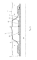
- Fig. 1 shows an annular barrier 1 to be expanded in an annulus 2 between a well tubular structure 3 and an inside wall 4 of a borehole 5 downhole for providing zone isolation between a first zone 8 and a second zone 12 of the borehole 5.
- the tubular structure 3 may be a production casing.
- the annular barrier 1 comprises a tubular part 6 mounted as part of the well tubular structure 3.
- the tubular part 6 has a longitudinal axis 14 coaxial with the longitudinal axis of the well tubular structure 3.
- the annular barrier 1 comprises an expandable sleeve 7 surrounding the tubular part 6 and defining a space 13 which is in fluid communication with an inside 23 of the tubular part 6.
- Each end 9, 10 of the expandable sleeve 7 is connected with the tubular part 6, one end being fixedly fastened to the tubular part and the other end being slidably fastened with the tubular part.
- the annular barrier 1 has an aperture 11 for letting fluid into the space to expand the sleeve, the aperture 11 being arranged in the tubular part 6 so that the fluid is let directly into the space.
- the aperture may be arranged so that the fluid is let from the inside of the tubular part through a connection part 15 fastening the expandable sleeve 7 with the tubular part.
- a valve may also be arranged in the aperture, such as a one-way valve, and when the aperture is the connection part also a two-way valve or three-way valve.
- the expandable sleeve is typically expanded by pressurising the well tubular structure 3 from the top of the well and in this way inflate several annular barriers at a time.
- the annular barrier further comprises a compensation device 16 having a chamber 17 in which a piston 18 is arranged dividing the chamber 17 in a first chamber part 19 and a second chamber part 20.
- the first chamber part 19 is in fluid communication with the space 13 through an opening 21 and the second chamber part 20 comprises gas, such nitrogen.
- the gas may also be neon, argon, krypton, or xenon.
- the compensation device 16 is arranged in the space 13 between the expandable sleeve 7 and the tubular part 6.
- the annular barrier 1 has been expanded by pressurising the inside of the tubular part and thus fluid is flowing into the aperture to pressurise the space 13 to expand the expandable sleeve 7.
- the pressure in the space may drop accordingly and thus cause a pressure drop in relation to the formation pressure and the pressure in the annulus.
- the temperature drop may cause the expandable sleeve to collapse locally, undermining its strength, and the pressure to make it collapse, also called the collapse pressure, is somewhat decreased.
- the piston 18 of the compensation device moves towards the opening, as shown in Fig.
- the compensation device lets fluid out into the space to equalise the pressure until it is the same as the pressure before the temperature drop.
- the piston When the temperature increases in the borehole, the piston is forced to move to reduce the second chamber part 20, 20B due to the fact that the gas in the second chamber part diminishes to equalise the pressure inside the space.
- the annular barrier 1 is arranged in a vertical part of the well.
- the second chamber part 20 is arranged closest to the fixedly connected end of the expandable sleeve 7.
- the annular barrier 1 may also be arranged in the horizontal part of the well and then the gas will accumulate underneath the expandable sleeve closest to the borehole wall 4 and will, in the same way as in Fig. 4 , have the ability to expand and thus equalise the pressure.
- the compensation device is arranged as part of the fixed connection part 24 connecting the expandable sleeve 7 with the tubular part 6, since the slidable connection part 25 slidably connecting the expandable sleeve with the tubular part moves during expansion and thus moves in relation to the aperture in the tubular part if the aperture is arranged in connection with the connection part, and thus the expansion fluid is let in through that connection part.
- the position of the aperture is thus optional.
- the annular barrier comprises an additional connection part being the slidable connection part 25 in which a second compensation device 16B is arranged.
- the second compensation device 16B comprises a chamber 17B in which a piston 18B is arranged dividing the chamber 17B in a first chamber part 19B and a second chamber part 20B.
- the first chamber part 19B is in fluid communication with the space 13 through an opening 21B and the second chamber part 20B also comprises gas, such nitrogen.
- the gas may also be neon, argon, krypton, or xenon.
- the compensation device 16B is arranged in the space 13 between the expandable sleeve 7 and the tubular part 6.
- the chamber is annular, surrounding the tubular part.
- the first chamber part 19, 19B and the second chamber part 20, 20B is also annular and the piston 18, 18B moving inside the chamber 17, 17B is a ring-shaped piston surrounding the tubular part 6.
- the compensation device 16, 16B has a plurality of chambers 17, 17B spaced along a circumference of the tubular part and the connection part 15.
- a piston 18, 18B is arranged in each chamber 17, 17B diving the chamber into a first and a second chamber part as mentioned above.
- Fig. 7 is a cross-sectional view of the connection part 15, and by having several chambers instead of one annular chamber, the connection part becomes more rigid and solid and thus capable of withstanding the pressure difference occurring downhole and the bumping when lowering the well tubular structure in order to complete the well.
- Fig. 8 an embodiment of the compensation device is shown.
- the piston 18, 18B comprises a sealing means 26, such as an O-ring to seal the second chamber part 20, 20B from the first chamber part 19, 19B.
- the second chamber part comprises a valve 27 accessible from the inside 23 of the tubular part in order to be able to refill the second chamber part 20, 20B with gas if needed later.
- the valve may be any kind of suitable valve.
- the method for maintaining a pressure within the annular barrier 1 mentioned above is firstly to expand the expandable sleeve until the sleeve seals against the inside wall 4 of the borehole, and subsequently, when the temperature decreases or increases in the borehole, to equalise the pressure inside the space by moving the piston 18, 18B and let the gas in the second chamber part expand or diminish.
- the expandable sleeve 7 has an outer face facing the wall 4 of the borehole. Different kinds of sealing elements may be arranged on the outer face to increase the sealing ability of the sleeve towards the wall of the borehole.
- the invention also relates to a well system 100 comprising the well tubular structure 3 and the annular barrier 1.
- the well system 100 further comprises a tool 29 having an isolation means 30 isolating an isolated part 28 of the inside 23 of the tubular part outside the aperture 11 to pressurise the isolated part 28 of the inside 23 and thus the space 13 to expand the sleeve.
- the isolation means 30 may be an inflatable elastomeric element or a metal packer.
- the tool further comprises a pumping device 31 for pumping fluid from the inside of the tubular part being outside the isolated part 28 and into the isolated part 28 to expand the expandable sleeve 7.
- the well system may also have several annular barriers 1.
- the tool may also use coiled tubing for expanding the expandable sleeve of one annular barrier or two annular barriers at the same time.
- a tool with coiled tubing can pressurise the fluid in the well tubular structure without having to isolate a section of the well tubular structure.
- the tool may need to plug the well tubular structure further down the borehole for the two annular barriers to be operated.
- the tool comprises a reservoir containing the pressurised fluid, e.g. when the fluid used for expanding the sleeve is cement, gas, or a two-component compound.
- the space 13 may also be prefilled with some kind of fluid, such as a hardening agent, cement or the like.
- An annular barrier may also be called a packer or similar expandable means.
- the well tubular structure can be the production tubing or casing or a similar kind of tubing downhole in a well or a borehole.
- the annular barrier can be used both in between the inner production tubing and an outer tubing in the borehole or between a tubing and the inner wall of the borehole.
- a well may have several kinds of tubing and the annular barrier of the present invention can be mounted for use in all of them.
- the valve may be any kind of valve capable of controlling flow, such as a ball valve, butterfly valve, choke valve, check valve or non-return valve, diaphragm valve, expansion valve, gate valve, globe valve, knife valve, needle valve, piston valve, pinch valve, or plug valve.
- a ball valve such as a ball valve, butterfly valve, choke valve, check valve or non-return valve, diaphragm valve, expansion valve, gate valve, globe valve, knife valve, needle valve, piston valve, pinch valve, or plug valve.
- the expandable tubular metal sleeve may be a cold-drawn or hot-drawn tubular structure.
- the expandable sleeve 3 of the annular barrier 1 When the expandable sleeve 3 of the annular barrier 1 is expanded, the diameter of the sleeve is expanded from its initial unexpanded diameter to a larger diameter.
- the expandable sleeve 3 has an outside diameter D and is capable of expanding to an at least 10% larger diameter, preferably an at least 15% larger diameter, more preferably an at least 30% larger diameter than that of an unexpanded sleeve.
- the expandable sleeve 3 has a wall thickness t which is thinner than a length L of the expandable sleeve, the thickness preferably being less than 25% of the length, more preferably less than 15% of the length, and even more preferably less than 10% of the length.
- the expandable sleeve 3 of the annular barrier 1 may be made of metal, polymers, an elastomeric material, silicone, or natural or synthetic rubber.
- additional material may be applied (not shown) onto the expandable sleeve, e.g. by adding welded material onto the outer face.
- the thickness of the sleeve 3 is increased by fastening a ring-shaped part onto the sleeve (not shown).
- the increased thickness of the sleeve 3 is facilitated using a varying thickness sleeve 3 (not shown).
- a sleeve of varying thickness techniques such as rolling, extrusion or die-casting may be used.
- the fluid used for expanding the expandable sleeve may be any kind of well fluid present in the borehole surrounding the tool and/or the well tubular structure 3.
- the fluid may be cement, gas, water, polymers, or a two-component compound, such as powder or particles mixing or reacting with a binding or hardening agent.
- Part of the fluid, such as the hardening agent may be present in the cavity between the tubular part and the expandable sleeve before injecting a subsequent fluid into the cavity.
- fluid or well fluid any kind of fluid that may be present in oil or gas wells downhole, such as natural gas, oil, oil mud, crude oil, water, etc.
- gas is meant any kind of gas composition present in a well, completion, or open hole
- oil is meant any kind of oil composition, such as crude oil, an oil-containing fluid, etc.
- Gas, oil, and water fluids may thus all comprise other elements or substances than gas, oil, and/or water, respectively.
- a casing any kind of pipe, tubing, tubular, liner, string etc. used downhole in relation to oil or natural gas production.
- a downhole tractor can be used to push the tools all the way into position in the well.
- a downhole tractor is any kind of driving tool capable of pushing or pulling tools in a well downhole, such as a Well Tractor®.
- a downhole tractor may have wheels on arms projecting from a tool housing of the tractor, or driving belts for moving the tractor forward in the well.
Landscapes
- Geology (AREA)
- Life Sciences & Earth Sciences (AREA)
- Engineering & Computer Science (AREA)
- Mining & Mineral Resources (AREA)
- Environmental & Geological Engineering (AREA)
- Fluid Mechanics (AREA)
- Physics & Mathematics (AREA)
- General Life Sciences & Earth Sciences (AREA)
- Geochemistry & Mineralogy (AREA)
- Geophysics And Detection Of Objects (AREA)
- Pipe Accessories (AREA)
- Earth Drilling (AREA)
- Pit Excavations, Shoring, Fill Or Stabilisation Of Slopes (AREA)
- Fluid-Damping Devices (AREA)
Abstract
An annular barrier (1) to be expanded in an annulus (2) between a well tubular structure (3) and an inside wall (4) of a borehole downhole for providing zone isolation between a first zone and a second zone of the borehole, comprising a tubular part (6) for mounting as part of the well tubular structure, said tubular part having a longitudinal axis, an expandable sleeve (7) surrounding the tubular part and defining a space (13) being in fluid communication with an inside of the tubular part, each end (9,10) of the expandable sleeve being connected with the tubular part, and an aperture (11) for letting fluid into the space to expand the sleeve, wherein the barrier further comprises a compensation device (16) having a chamber in which a piston (18) is arranged dividing the chamber in a first and a second chamber part, the first chamber part (19) being in fluid communication with the space and the second chamber part (20) comprising gas.
Description
- The present invention relates to an annular barrier to be expanded in an annulus between a well tubular structure and an inside wall of a borehole downhole for providing zone isolation between a first zone and a second zone of the borehole. The invention furthermore relates to a well system and to a method for maintaining a pressure within the annular barrier.
- In wellbores, annular barriers are used for different purposes, such as for providing a barrier for flow between an inner and an outer tubular structure or between an inner tubular structure and the inner wall of the borehole. The annular barriers are mounted as part of the well tubular structure. An annular barrier has an inner wall surrounded by an annular expandable sleeve. The expandable sleeve is typically made of an elastomeric material, but may also be made of metal. The sleeve is fastened at its ends to the inner wall of the annular barrier.
- In order to seal off a zone between an inner and an outer tubular structure or a well tubular structure and the borehole, a second annular barrier is used. The first annular barrier is expanded on one side of the zone to be sealed off, and the second annular barrier is expanded on the other side of that zone, and in this way, the zone is sealed off.
- When expanded, annular barriers may be subjected to a continuous pressure or a periodic high pressure from the outside, either in the form of hydraulic pressure within the well environment or in the form of formation pressure. In some circumstances, such pressure may cause the annular barrier to collapse, which may have severe consequences for the area which the barrier is to seal off as the sealing properties are lost due to the collapse. A similar problem may arise when the expandable sleeve is expanded by means of e.g. a pressurised fluid. If the fluid leaks from the sleeve, the back pressure may fade, and the sleeve itself may thus collapse.
- The ability of the expanded sleeve of an annular barrier to withstand the collapse pressure is thus affected by many variables, such as strength of material, wall thickness, surface area exposed to the collapse pressure, temperature, well fluids, etc.
- The collapse rating currently achievable by the expanded sleeve within certain well environments is insufficient for all well applications. Thus, it is desirable to increase the collapse rating to enable annular barriers to be used in all wells, specifically in wells that experience a high drawdown pressure during production and depletion. The collapse rating may be increased by increasing the wall thickness or the strength of the material; however, this would increase the expansion pressure, which, as mentioned, is not desirable.
- It is an object of the present invention to wholly or partly overcome the above disadvantages and drawbacks of the prior art. More specifically, it is an object to provide an improved annular barrier wherein the collapse rating of the annular barrier is increased to withstand the conditions downhole to which it is exposed.
- The above objects, together with numerous other objects, advantages, and features, which will become evident from the below description, are accomplished by a solution in accordance with the present invention by an annular barrier to be expanded in an annulus between a well tubular structure and an inside wall of a borehole downhole for providing zone isolation between a first zone and a second zone of the borehole, comprising
- a tubular part for mounting as part of the well tubular structure, said tubular part having a longitudinal axis,
- an expandable sleeve surrounding the tubular part and defining a space being in fluid communication with an inside of the tubular part, each end of the expandable sleeve being connected with the tubular part, and
- an aperture for letting fluid into the space to expand the sleeve,
- Said gas may be nitrogen, neon, argon, krypton, or xenon.
- In one embodiment, the compensation device may be arranged in the space between the expandable sleeve and the tubular part.
- In another embodiment, the compensation device may be arranged as part of a connection part connecting the expandable sleeve with the tubular part.
- Further, the annular barrier may comprise an additional connection part wherein a second compensation device is arranged.
- Also, the chamber of the compensation device may be annular, surrounding the tubular part.
- Said compensation device may have several chambers in which pistons are arranged.
- This plurality of chambers may be spaced along a circumference of the tubular part.
- Moreover, one end of the sleeve may be fixedly fastened to the tubular part and the other end may be slidably fastened to the tubular part, and the second chamber part containing the gas may be arranged closest to the fixedly connected end of the sleeve.
- In addition, the second chamber part may comprise a valve accessible from the inside of the tubular part, allowing refill of the second chamber part with gas.
- Furthermore, the piston may comprise sealing means to seal the second chamber part from the first chamber part.
- The present invention also relates to a well system comprising the well tubular structure and the annular barrier described above.
- The well system according the present invention may further have a tool comprising isolation means isolating an isolated part of the inside of the tubular part outside the aperture to pressurise the isolated part of the inside and the space to expand the expandable sleeve.
- Said tool may further comprise a pumping device for pumping fluid from the inside of the tubular part being outside the isolated part and into the isolated part to expand the expandable sleeve.
- Finally, the present invention relates to a method for maintaining a pressure within the annular barrier described above, comprising the steps of:
- expanding the expandable sleeve until the sleeve seals against the inside wall of the borehole,
- equalising the pressure inside the space when the temperature decreases or increases in the borehole by moving the piston and letting the gas in the second chamber part expand or diminish.
- The invention and its many advantages will be described in more detail below with reference to the accompanying schematic drawings, which for the purpose of illustration show some non-limiting embodiments and in which
-
Fig. 1 shows a cross-sectional view of an annular barrier with a compensation device in its unexpanded condition, -
Fig. 2 shows the annular barrier ofFig. 1 in its expanded condition, -
Fig. 3 shows the annular barrier ofFig. 1 in its expanded condition while the compensation device has equalised the pressure in relation toFig. 2 , -
Fig. 4 shows a cross-sectional view of another embodiment of the annular barrier in a vertical well, -
Fig. 5 shows a cross-sectional view of yet another embodiment of the annular barrier, -
Fig. 6 shows a cross-sectional view of yet another embodiment of the annular barrier and a well system, -
Fig. 7 shows a cross-sectional view of the connection part of yet another embodiment of the annular barrier, and -
Fig. 8 shows a cross-sectional view of the compensation device. - All the figures are highly schematic and not necessarily to scale, and they show only those parts which are necessary in order to elucidate the invention, other parts being omitted or merely suggested.
-
Fig. 1 shows anannular barrier 1 to be expanded in anannulus 2 between a welltubular structure 3 and aninside wall 4 of a borehole 5 downhole for providing zone isolation between afirst zone 8 and asecond zone 12 of the borehole 5. Thetubular structure 3 may be a production casing. Theannular barrier 1 comprises atubular part 6 mounted as part of the welltubular structure 3. Thetubular part 6 has alongitudinal axis 14 coaxial with the longitudinal axis of the welltubular structure 3. Theannular barrier 1 comprises anexpandable sleeve 7 surrounding thetubular part 6 and defining aspace 13 which is in fluid communication with aninside 23 of thetubular part 6. Eachend expandable sleeve 7 is connected with thetubular part 6, one end being fixedly fastened to the tubular part and the other end being slidably fastened with the tubular part. - The
annular barrier 1 has anaperture 11 for letting fluid into the space to expand the sleeve, theaperture 11 being arranged in thetubular part 6 so that the fluid is let directly into the space. In another embodiment, the aperture may be arranged so that the fluid is let from the inside of the tubular part through aconnection part 15 fastening theexpandable sleeve 7 with the tubular part. A valve may also be arranged in the aperture, such as a one-way valve, and when the aperture is the connection part also a two-way valve or three-way valve. The expandable sleeve is typically expanded by pressurising the welltubular structure 3 from the top of the well and in this way inflate several annular barriers at a time. - The annular barrier further comprises a
compensation device 16 having achamber 17 in which apiston 18 is arranged dividing thechamber 17 in afirst chamber part 19 and asecond chamber part 20. Thefirst chamber part 19 is in fluid communication with thespace 13 through anopening 21 and thesecond chamber part 20 comprises gas, such nitrogen. The gas may also be neon, argon, krypton, or xenon. Thecompensation device 16 is arranged in thespace 13 between theexpandable sleeve 7 and thetubular part 6. - In
Fig. 2 , theannular barrier 1 has been expanded by pressurising the inside of the tubular part and thus fluid is flowing into the aperture to pressurise thespace 13 to expand theexpandable sleeve 7. When the temperature drops in the annulus, then the pressure in the space may drop accordingly and thus cause a pressure drop in relation to the formation pressure and the pressure in the annulus. Thus, the temperature drop may cause the expandable sleeve to collapse locally, undermining its strength, and the pressure to make it collapse, also called the collapse pressure, is somewhat decreased. In order to avoid the pressure drop and thus the decrease in collapse pressure, thepiston 18 of the compensation device moves towards the opening, as shown inFig. 3 , due to the pressure inside thefirst chamber part 19 being the same decreased pressure as the pressure inside thespace 13. The gas inside thesecond chamber part 20 expands to equalise the pressure difference between the first and the second chamber part. In this way, the compensation device lets fluid out into the space to equalise the pressure until it is the same as the pressure before the temperature drop. - When the temperature increases in the borehole, the piston is forced to move to reduce the
second chamber part - In
Fig. 4 , theannular barrier 1 is arranged in a vertical part of the well. Thesecond chamber part 20 is arranged closest to the fixedly connected end of theexpandable sleeve 7. By having the compensation device inside thespace 13 and thesecond chamber part 20 arranged closest to the fixedly connected end of the expandable sleeve, any leak ofgas 40 in thecompensation device 16 will result in the accumulation ofgas 40 in the top part of thespace 13. By having the gas arranged in the top part, the gas will still have the ability to expand and thus equalise the pressure during a temperature drop in the fluid in the annulus. - The
annular barrier 1 may also be arranged in the horizontal part of the well and then the gas will accumulate underneath the expandable sleeve closest to theborehole wall 4 and will, in the same way as inFig. 4 , have the ability to expand and thus equalise the pressure. - In
Fig. 5 , the compensation device is arranged as part of the fixedconnection part 24 connecting theexpandable sleeve 7 with thetubular part 6, since theslidable connection part 25 slidably connecting the expandable sleeve with the tubular part moves during expansion and thus moves in relation to the aperture in the tubular part if the aperture is arranged in connection with the connection part, and thus the expansion fluid is let in through that connection part. The position of the aperture is thus optional. - In
Fig. 6 , the annular barrier comprises an additional connection part being theslidable connection part 25 in which asecond compensation device 16B is arranged. Thesecond compensation device 16B comprises achamber 17B in which a piston 18B is arranged dividing thechamber 17B in afirst chamber part 19B and asecond chamber part 20B. Thefirst chamber part 19B is in fluid communication with thespace 13 through anopening 21B and thesecond chamber part 20B also comprises gas, such nitrogen. The gas may also be neon, argon, krypton, or xenon. Thecompensation device 16B is arranged in thespace 13 between theexpandable sleeve 7 and thetubular part 6. - As can be seen from the cross-sectional views of
Figs. 1-6 , the chamber is annular, surrounding the tubular part. Thus, thefirst chamber part second chamber part piston 18, 18B moving inside thechamber tubular part 6. - In
Fig. 7 , thecompensation device chambers connection part 15. Apiston 18, 18B is arranged in eachchamber Fig. 7 is a cross-sectional view of theconnection part 15, and by having several chambers instead of one annular chamber, the connection part becomes more rigid and solid and thus capable of withstanding the pressure difference occurring downhole and the bumping when lowering the well tubular structure in order to complete the well. InFig. 8 , an embodiment of the compensation device is shown. As can be seen, thepiston 18, 18B comprises a sealing means 26, such as an O-ring to seal thesecond chamber part first chamber part valve 27 accessible from the inside 23 of the tubular part in order to be able to refill thesecond chamber part - The method for maintaining a pressure within the
annular barrier 1 mentioned above is firstly to expand the expandable sleeve until the sleeve seals against theinside wall 4 of the borehole, and subsequently, when the temperature decreases or increases in the borehole, to equalise the pressure inside the space by moving thepiston 18, 18B and let the gas in the second chamber part expand or diminish. - The
expandable sleeve 7 has an outer face facing thewall 4 of the borehole. Different kinds of sealing elements may be arranged on the outer face to increase the sealing ability of the sleeve towards the wall of the borehole. - As can be seen in
Fig. 6 , the invention also relates to a well system 100 comprising the welltubular structure 3 and theannular barrier 1. The well system 100 further comprises atool 29 having an isolation means 30 isolating anisolated part 28 of the inside 23 of the tubular part outside theaperture 11 to pressurise theisolated part 28 of the inside 23 and thus thespace 13 to expand the sleeve. The isolation means 30 may be an inflatable elastomeric element or a metal packer. The tool further comprises apumping device 31 for pumping fluid from the inside of the tubular part being outside theisolated part 28 and into theisolated part 28 to expand theexpandable sleeve 7. The well system may also have severalannular barriers 1. - The tool may also use coiled tubing for expanding the expandable sleeve of one annular barrier or two annular barriers at the same time. A tool with coiled tubing can pressurise the fluid in the well tubular structure without having to isolate a section of the well tubular structure. However, the tool may need to plug the well tubular structure further down the borehole for the two annular barriers to be operated.
- In one embodiment, the tool comprises a reservoir containing the pressurised fluid, e.g. when the fluid used for expanding the sleeve is cement, gas, or a two-component compound. The
space 13 may also be prefilled with some kind of fluid, such as a hardening agent, cement or the like. - An annular barrier may also be called a packer or similar expandable means. The well tubular structure can be the production tubing or casing or a similar kind of tubing downhole in a well or a borehole. The annular barrier can be used both in between the inner production tubing and an outer tubing in the borehole or between a tubing and the inner wall of the borehole. A well may have several kinds of tubing and the annular barrier of the present invention can be mounted for use in all of them.
- The valve may be any kind of valve capable of controlling flow, such as a ball valve, butterfly valve, choke valve, check valve or non-return valve, diaphragm valve, expansion valve, gate valve, globe valve, knife valve, needle valve, piston valve, pinch valve, or plug valve.
- The expandable tubular metal sleeve may be a cold-drawn or hot-drawn tubular structure.
- When the
expandable sleeve 3 of theannular barrier 1 is expanded, the diameter of the sleeve is expanded from its initial unexpanded diameter to a larger diameter. Theexpandable sleeve 3 has an outside diameter D and is capable of expanding to an at least 10% larger diameter, preferably an at least 15% larger diameter, more preferably an at least 30% larger diameter than that of an unexpanded sleeve. - Furthermore, the
expandable sleeve 3 has a wall thickness t which is thinner than a length L of the expandable sleeve, the thickness preferably being less than 25% of the length, more preferably less than 15% of the length, and even more preferably less than 10% of the length. - The
expandable sleeve 3 of theannular barrier 1 may be made of metal, polymers, an elastomeric material, silicone, or natural or synthetic rubber. - In order to increase the thickness of the
sleeve 3, additional material may be applied (not shown) onto the expandable sleeve, e.g. by adding welded material onto the outer face. - In another embodiment, the thickness of the
sleeve 3 is increased by fastening a ring-shaped part onto the sleeve (not shown). - In yet another embodiment, the increased thickness of the
sleeve 3 is facilitated using a varying thickness sleeve 3 (not shown). To obtain a sleeve of varying thickness, techniques such as rolling, extrusion or die-casting may be used. - The fluid used for expanding the expandable sleeve may be any kind of well fluid present in the borehole surrounding the tool and/or the well
tubular structure 3. Also, the fluid may be cement, gas, water, polymers, or a two-component compound, such as powder or particles mixing or reacting with a binding or hardening agent. Part of the fluid, such as the hardening agent, may be present in the cavity between the tubular part and the expandable sleeve before injecting a subsequent fluid into the cavity. - By fluid or well fluid is meant any kind of fluid that may be present in oil or gas wells downhole, such as natural gas, oil, oil mud, crude oil, water, etc. By gas is meant any kind of gas composition present in a well, completion, or open hole, and by oil is meant any kind of oil composition, such as crude oil, an oil-containing fluid, etc. Gas, oil, and water fluids may thus all comprise other elements or substances than gas, oil, and/or water, respectively.
- By a casing is meant any kind of pipe, tubing, tubular, liner, string etc. used downhole in relation to oil or natural gas production.
- In the event that the tool is not submergible all the way into the casing, a downhole tractor can be used to push the tools all the way into position in the well. A downhole tractor is any kind of driving tool capable of pushing or pulling tools in a well downhole, such as a Well Tractor®. A downhole tractor may have wheels on arms projecting from a tool housing of the tractor, or driving belts for moving the tractor forward in the well.
- Although the invention has been described in the above in connection with preferred embodiments of the invention, it will be evident for a person skilled in the art that several modifications are conceivable without departing from the invention as defined by the following claims.
Claims (14)
- An annular barrier (1) to be expanded in an annulus (2) between a well tubular structure (3) and an inside wall (4) of a borehole (5) downhole for providing zone isolation between a first zone and a second zone of the borehole, comprising- a tubular part (6) for mounting as part of the well tubular structure (3), said tubular part having a longitudinal axis,- an expandable sleeve (7) surrounding the tubular part and defining a space (13) being in fluid communication with an inside of the tubular part, each end (9, 10) of the expandable sleeve being connected with the tubular part, and- an aperture (11) for letting fluid into the space to expand the sleeve,
wherein the barrier further comprises a compensation device having a chamber in which a piston is arranged dividing the chamber in a first and a second chamber part, the first chamber part being in fluid communication with the space and the second chamber part comprising gas. - An annular barrier according to claim 1, wherein the gas is nitrogen, neon, argon, krypton, or xenon.
- An annular barrier according to claim 1 or 2, wherein the compensation device is arranged in the space between the expandable sleeve and the tubular part.
- An annular barrier according to claim 1 or 2, wherein the compensation device is arranged as part of a connection part connecting the expandable sleeve with the tubular part.
- An annular barrier according to claim 4, wherein the annular barrier comprises an additional connection part wherein a second compensation device is arranged.
- An annular barrier according to any of the preceding claims, wherein the chamber is annular, surrounding the tubular part.
- An annular barrier according to any of claims 1-5, wherein the compensation device has several chambers in which pistons are arranged.
- An annular barrier according to any of the preceding claims, wherein one end of the sleeve is fixedly fastened to the tubular part and the other end is slidably fastened to the tubular part, and wherein the second chamber part containing the gas is arranged closest to the fixedly connected end of the sleeve.
- An annular barrier according to any of the preceding claims, wherein the second chamber part comprises a valve accessible from the inside of the tubular part, allowing refill of the second chamber part with gas.
- An annular barrier according to any of the preceding claims, wherein the piston comprises sealing means to seal the second chamber part from the first chamber part.
- A well system comprising the well tubular structure and the annular barrier according to any of the claims 1-10.
- A well system according claim 11, further having a tool (29) comprising isolation means (30) isolating an isolated part (28) of the inside (23) of the tubular part outside the aperture (11) to pressurise the isolated part (28) of the inside (23) and the space (13) to expand the expandable sleeve (7).
- A well system according claim 12, wherein the tool further comprises a pumping device (31) for pumping fluid from the inside of the tubular part being outside the isolated part (28) and into the isolated part (28) to expand the expandable sleeve.
- A method for maintaining a pressure within the annular barrier according to any of claims 1-10, comprising the steps of:- expanding the expandable sleeve until the sleeve seals against the inside wall of the borehole,- equalising the pressure inside the space when the temperature decreases or increases in the borehole by moving the piston and letting the gas in the second chamber part expand or diminish.
Priority Applications (11)
| Application Number | Priority Date | Filing Date | Title |
|---|---|---|---|
| EP11179546A EP2565369A1 (en) | 2011-08-31 | 2011-08-31 | Annular barrier with compensation device |
| BR112014003428A BR112014003428A2 (en) | 2011-08-31 | 2012-08-30 | ring barrier with compensation device |
| US14/238,251 US20140190683A1 (en) | 2011-08-31 | 2012-08-30 | Annular barrier with compensation device |
| MX2014001742A MX2014001742A (en) | 2011-08-31 | 2012-08-30 | Annular barrier with compensation device. |
| PCT/EP2012/066871 WO2013030284A1 (en) | 2011-08-31 | 2012-08-30 | Annular barrier with compensation device |
| AU2012300925A AU2012300925B2 (en) | 2011-08-31 | 2012-08-30 | Annular barrier with compensation device |
| IN459CHN2014 IN2014CN00459A (en) | 2011-08-31 | 2012-08-30 | |
| EP12751524.5A EP2751383A1 (en) | 2011-08-31 | 2012-08-30 | Annular barrier with compensation device |
| CA2845495A CA2845495A1 (en) | 2011-08-31 | 2012-08-30 | Annular barrier with compensation device |
| CN201280039683.0A CN103732851A (en) | 2011-08-31 | 2012-08-30 | Annular barrier with compensation device |
| RU2014109696/03A RU2014109696A (en) | 2011-08-31 | 2012-08-30 | ANNEX BARRIER WITH COMPENSATION DEVICE |
Applications Claiming Priority (1)
| Application Number | Priority Date | Filing Date | Title |
|---|---|---|---|
| EP11179546A EP2565369A1 (en) | 2011-08-31 | 2011-08-31 | Annular barrier with compensation device |
Publications (1)
| Publication Number | Publication Date |
|---|---|
| EP2565369A1 true EP2565369A1 (en) | 2013-03-06 |
Family
ID=46755007
Family Applications (2)
| Application Number | Title | Priority Date | Filing Date |
|---|---|---|---|
| EP11179546A Withdrawn EP2565369A1 (en) | 2011-08-31 | 2011-08-31 | Annular barrier with compensation device |
| EP12751524.5A Withdrawn EP2751383A1 (en) | 2011-08-31 | 2012-08-30 | Annular barrier with compensation device |
Family Applications After (1)
| Application Number | Title | Priority Date | Filing Date |
|---|---|---|---|
| EP12751524.5A Withdrawn EP2751383A1 (en) | 2011-08-31 | 2012-08-30 | Annular barrier with compensation device |
Country Status (10)
| Country | Link |
|---|---|
| US (1) | US20140190683A1 (en) |
| EP (2) | EP2565369A1 (en) |
| CN (1) | CN103732851A (en) |
| AU (1) | AU2012300925B2 (en) |
| BR (1) | BR112014003428A2 (en) |
| CA (1) | CA2845495A1 (en) |
| IN (1) | IN2014CN00459A (en) |
| MX (1) | MX2014001742A (en) |
| RU (1) | RU2014109696A (en) |
| WO (1) | WO2013030284A1 (en) |
Cited By (1)
| Publication number | Priority date | Publication date | Assignee | Title |
|---|---|---|---|---|
| FR3041681A1 (en) * | 2015-09-28 | 2017-03-31 | Gerard Arsonnet | PRESSIOMETRIC PROBE |
Families Citing this family (16)
| Publication number | Priority date | Publication date | Assignee | Title |
|---|---|---|---|---|
| US9551201B2 (en) | 2008-02-19 | 2017-01-24 | Weatherford Technology Holdings, Llc | Apparatus and method of zonal isolation |
| FR3016389B1 (en) * | 2014-01-10 | 2016-01-08 | Saltel Ind | ISOLATION DEVICE FOR WELLS |
| GB2556457B (en) * | 2015-04-30 | 2021-10-13 | Koki Holdings Co Ltd | Fastener driving machine |
| EP3088654A1 (en) * | 2015-04-30 | 2016-11-02 | Welltec A/S | Annular barrier with expansion unit |
| FR3038932B1 (en) * | 2015-07-15 | 2018-08-17 | Saltel Ind | ISOLATION DEVICE FOR WELLS WITH BREAK DISC |
| WO2017089343A1 (en) * | 2015-11-23 | 2017-06-01 | Welltec A/S | Annular barrier completion with inductive system |
| CA3010423A1 (en) * | 2016-01-26 | 2017-08-03 | Welltec A/S | Annular barrier and downhole system for low pressure zone |
| EP3244002A1 (en) * | 2016-05-09 | 2017-11-15 | Welltec A/S | Geothermal energy extraction subterranean system |
| BR112018073987A2 (en) * | 2016-05-30 | 2019-02-26 | Welltec Oilfield Solutions Ag | downhole completion apparatus with liquid |
| CN107313739B (en) * | 2017-09-06 | 2020-07-17 | 成都百胜野牛科技有限公司 | Fluid separation device, well structure and method for producing oil or gas |
| CN109162664B (en) * | 2018-10-24 | 2023-10-20 | 中国石油化工股份有限公司 | Downhole metal packer and methods of making and using the same |
| CN113898790B (en) * | 2020-06-22 | 2023-03-14 | 中国航发商用航空发动机有限责任公司 | Pipe support and thermal deformation compensation device for same |
| BR112022027070A2 (en) | 2020-07-02 | 2023-03-07 | Schlumberger Technology Bv | COMPLETION INSULATION SYSTEM WITH PIPE MOVEMENT COMPENSATOR |
| CN113047791B (en) * | 2021-04-06 | 2023-02-24 | 中国石油天然气集团有限公司 | Heavy oil thermal recovery top water channeling and multistage steam channeling prevention method |
| US12486737B2 (en) * | 2023-09-08 | 2025-12-02 | Welltec Manufacturing Center Completions ApS | Annular barrier and downhole system |
| EP4650563A1 (en) * | 2024-05-17 | 2025-11-19 | Welltec Manufacturing Center Completions ApS | Completion component |
Citations (8)
| Publication number | Priority date | Publication date | Assignee | Title |
|---|---|---|---|---|
| SU1113514A1 (en) * | 1982-06-29 | 1984-09-15 | Всесоюзный Ордена Трудового Красного Знамени Научно-Исследовательский Институт Буровой Техники | Hydraulic packer |
| US4655292A (en) * | 1986-07-16 | 1987-04-07 | Baker Oil Tools, Inc. | Steam injection packer actuator and method |
| WO1998036152A1 (en) * | 1997-02-14 | 1998-08-20 | Weatherford/Lamb, Inc. | Inflatable downhole seal |
| WO2000063523A1 (en) * | 1999-04-15 | 2000-10-26 | Weatherford/Lamb, Inc. | Apparatus for maintaining uniform pressure within an expandable well tool |
| GB2349657A (en) * | 1999-04-12 | 2000-11-08 | Baker Hughes Inc | Inflatable packer temperature and pressure compensation |
| US20070056749A1 (en) * | 2005-09-14 | 2007-03-15 | Schlumberger Technology Corporation | Dynamic Inflatable Sealing Device |
| WO2007031723A2 (en) * | 2005-09-14 | 2007-03-22 | Petrowell Limited | Packer |
| WO2008060297A2 (en) * | 2006-11-15 | 2008-05-22 | Halliburton Energy Services, Inc. | Well tool including swellable material and integrated fluid for initiating swelling |
Family Cites Families (3)
| Publication number | Priority date | Publication date | Assignee | Title |
|---|---|---|---|---|
| US4260164A (en) * | 1979-06-15 | 1981-04-07 | Halliburton Company | Inflatable packer assembly with control valve |
| CN2707948Y (en) * | 2004-06-10 | 2005-07-06 | 潘昌德 | Hydropneumatic packer |
| GB0417328D0 (en) * | 2004-08-04 | 2004-09-08 | Read Well Services Ltd | Apparatus and method |
-
2011
- 2011-08-31 EP EP11179546A patent/EP2565369A1/en not_active Withdrawn
-
2012
- 2012-08-30 BR BR112014003428A patent/BR112014003428A2/en not_active IP Right Cessation
- 2012-08-30 IN IN459CHN2014 patent/IN2014CN00459A/en unknown
- 2012-08-30 RU RU2014109696/03A patent/RU2014109696A/en not_active Application Discontinuation
- 2012-08-30 AU AU2012300925A patent/AU2012300925B2/en not_active Ceased
- 2012-08-30 CA CA2845495A patent/CA2845495A1/en not_active Abandoned
- 2012-08-30 US US14/238,251 patent/US20140190683A1/en not_active Abandoned
- 2012-08-30 MX MX2014001742A patent/MX2014001742A/en not_active Application Discontinuation
- 2012-08-30 EP EP12751524.5A patent/EP2751383A1/en not_active Withdrawn
- 2012-08-30 CN CN201280039683.0A patent/CN103732851A/en active Pending
- 2012-08-30 WO PCT/EP2012/066871 patent/WO2013030284A1/en not_active Ceased
Patent Citations (8)
| Publication number | Priority date | Publication date | Assignee | Title |
|---|---|---|---|---|
| SU1113514A1 (en) * | 1982-06-29 | 1984-09-15 | Всесоюзный Ордена Трудового Красного Знамени Научно-Исследовательский Институт Буровой Техники | Hydraulic packer |
| US4655292A (en) * | 1986-07-16 | 1987-04-07 | Baker Oil Tools, Inc. | Steam injection packer actuator and method |
| WO1998036152A1 (en) * | 1997-02-14 | 1998-08-20 | Weatherford/Lamb, Inc. | Inflatable downhole seal |
| GB2349657A (en) * | 1999-04-12 | 2000-11-08 | Baker Hughes Inc | Inflatable packer temperature and pressure compensation |
| WO2000063523A1 (en) * | 1999-04-15 | 2000-10-26 | Weatherford/Lamb, Inc. | Apparatus for maintaining uniform pressure within an expandable well tool |
| US20070056749A1 (en) * | 2005-09-14 | 2007-03-15 | Schlumberger Technology Corporation | Dynamic Inflatable Sealing Device |
| WO2007031723A2 (en) * | 2005-09-14 | 2007-03-22 | Petrowell Limited | Packer |
| WO2008060297A2 (en) * | 2006-11-15 | 2008-05-22 | Halliburton Energy Services, Inc. | Well tool including swellable material and integrated fluid for initiating swelling |
Cited By (1)
| Publication number | Priority date | Publication date | Assignee | Title |
|---|---|---|---|---|
| FR3041681A1 (en) * | 2015-09-28 | 2017-03-31 | Gerard Arsonnet | PRESSIOMETRIC PROBE |
Also Published As
| Publication number | Publication date |
|---|---|
| BR112014003428A2 (en) | 2017-03-01 |
| AU2012300925B2 (en) | 2015-08-27 |
| AU2012300925A1 (en) | 2014-04-17 |
| RU2014109696A (en) | 2015-10-10 |
| MX2014001742A (en) | 2014-03-31 |
| CN103732851A (en) | 2014-04-16 |
| IN2014CN00459A (en) | 2015-04-03 |
| US20140190683A1 (en) | 2014-07-10 |
| WO2013030284A1 (en) | 2013-03-07 |
| CA2845495A1 (en) | 2013-03-07 |
| EP2751383A1 (en) | 2014-07-09 |
Similar Documents
| Publication | Publication Date | Title |
|---|---|---|
| EP2565369A1 (en) | Annular barrier with compensation device | |
| EP2706189B1 (en) | An annular barrier with a diaphragm | |
| CA2845490C (en) | Annular barrier with pressure amplification | |
| EP2538018A1 (en) | An annular barrier with external seal | |
| EP2312119A1 (en) | An annular barrier | |
| EP2586963A1 (en) | Sealing material for annular barriers | |
| EP2952672A1 (en) | Downhole expandable metal tubular | |
| AU2013241857B2 (en) | An annular barrier having a flexible connection | |
| MX2014010131A (en) | Expandable tubing run through production tubing and into open hole. | |
| AU2013100386B4 (en) | Annular barrier | |
| AU2013100385B4 (en) | Annular barrier | |
| AU2013100388A4 (en) | Annular barrier | |
| AU2013100387A4 (en) | Annular barrier |
Legal Events
| Date | Code | Title | Description |
|---|---|---|---|
| PUAI | Public reference made under article 153(3) epc to a published international application that has entered the european phase |
Free format text: ORIGINAL CODE: 0009012 |
|
| AK | Designated contracting states |
Kind code of ref document: A1 Designated state(s): AL AT BE BG CH CY CZ DE DK EE ES FI FR GB GR HR HU IE IS IT LI LT LU LV MC MK MT NL NO PL PT RO RS SE SI SK SM TR |
|
| AX | Request for extension of the european patent |
Extension state: BA ME |
|
| STAA | Information on the status of an ep patent application or granted ep patent |
Free format text: STATUS: THE APPLICATION IS DEEMED TO BE WITHDRAWN |
|
| 18D | Application deemed to be withdrawn |
Effective date: 20130907 |