EP2565118A2 - Aircraft lighting device - Google Patents
Aircraft lighting device Download PDFInfo
- Publication number
- EP2565118A2 EP2565118A2 EP12179023A EP12179023A EP2565118A2 EP 2565118 A2 EP2565118 A2 EP 2565118A2 EP 12179023 A EP12179023 A EP 12179023A EP 12179023 A EP12179023 A EP 12179023A EP 2565118 A2 EP2565118 A2 EP 2565118A2
- Authority
- EP
- European Patent Office
- Prior art keywords
- wing tip
- lighting device
- tip device
- electrical
- formation
- Prior art date
- Legal status (The legal status is an assumption and is not a legal conclusion. Google has not performed a legal analysis and makes no representation as to the accuracy of the status listed.)
- Withdrawn
Links
- 230000015572 biosynthetic process Effects 0.000 claims description 21
- 238000005286 illumination Methods 0.000 claims description 11
- 238000009434 installation Methods 0.000 claims description 3
- 230000004048 modification Effects 0.000 description 2
- 238000012986 modification Methods 0.000 description 2
- 230000000717 retained effect Effects 0.000 description 2
- 239000000853 adhesive Substances 0.000 description 1
- 230000001070 adhesive effect Effects 0.000 description 1
- 238000004519 manufacturing process Methods 0.000 description 1
Images


Classifications
-
- B—PERFORMING OPERATIONS; TRANSPORTING
- B64—AIRCRAFT; AVIATION; COSMONAUTICS
- B64C—AEROPLANES; HELICOPTERS
- B64C23/00—Influencing air flow over aircraft surfaces, not otherwise provided for
- B64C23/06—Influencing air flow over aircraft surfaces, not otherwise provided for by generating vortices
- B64C23/065—Influencing air flow over aircraft surfaces, not otherwise provided for by generating vortices at the wing tips
- B64C23/069—Influencing air flow over aircraft surfaces, not otherwise provided for by generating vortices at the wing tips using one or more wing tip airfoil devices, e.g. winglets, splines, wing tip fences or raked wingtips
-
- B—PERFORMING OPERATIONS; TRANSPORTING
- B64—AIRCRAFT; AVIATION; COSMONAUTICS
- B64D—EQUIPMENT FOR FITTING IN OR TO AIRCRAFT; FLIGHT SUITS; PARACHUTES; ARRANGEMENT OR MOUNTING OF POWER PLANTS OR PROPULSION TRANSMISSIONS IN AIRCRAFT
- B64D47/00—Equipment not otherwise provided for
- B64D47/02—Arrangements or adaptations of signal or lighting devices
-
- B—PERFORMING OPERATIONS; TRANSPORTING
- B64—AIRCRAFT; AVIATION; COSMONAUTICS
- B64D—EQUIPMENT FOR FITTING IN OR TO AIRCRAFT; FLIGHT SUITS; PARACHUTES; ARRANGEMENT OR MOUNTING OF POWER PLANTS OR PROPULSION TRANSMISSIONS IN AIRCRAFT
- B64D2203/00—Aircraft or airfield lights using LEDs
-
- Y—GENERAL TAGGING OF NEW TECHNOLOGICAL DEVELOPMENTS; GENERAL TAGGING OF CROSS-SECTIONAL TECHNOLOGIES SPANNING OVER SEVERAL SECTIONS OF THE IPC; TECHNICAL SUBJECTS COVERED BY FORMER USPC CROSS-REFERENCE ART COLLECTIONS [XRACs] AND DIGESTS
- Y02—TECHNOLOGIES OR APPLICATIONS FOR MITIGATION OR ADAPTATION AGAINST CLIMATE CHANGE
- Y02T—CLIMATE CHANGE MITIGATION TECHNOLOGIES RELATED TO TRANSPORTATION
- Y02T50/00—Aeronautics or air transport
- Y02T50/10—Drag reduction
Definitions
- the present invention is concerned with an aircraft lighting device. More specifically, the present invention is concerned with an aircraft wing tip device and associated lighting arrangement for illumination of the fuselage-facing side of the wing tip device.
- Wing tip devices are becoming increasingly common on commercial aircraft. Aside from the reduction of lift induced drag caused by wing tip vortices, wing tip devices also offer a vertically oriented area of the aircraft on which to place advertising and logos. In particular, the inward, fuselage-facing side of the wing tip device is visible to the passengers throughout the flight.
- wing tip devices are often designed into existing airframes, there is limited ability to integrate illumination devices on the wing itself in order to project onto the fuselage facing side of the wing tip device. As such, in dark conditions, the logo and/or advertising on the wing tip device is not visible.
- a solution for wing tip fuselage facing side illumination has been proposed in which light is projected from the fuselage. This is problematic as a light of significant power is required to reach the wing tip device, modifications required to the fuselage, alignment is difficult at such distances and furthermore the amount of light pollution and wasted energy created by such a device is significant.
- a wing tip device comprising:
- the unit does not require any modification to be made to the aircraft main wing or fuselage.
- the lighting device in the first portion of the wing tip device, better illumination of the surface of the second portion is possible.
- the lighting device defines an external surface, which external surface is flush with an external surface of the first portion.
- the lighting device comprises a glazing component arranged to form a substantially uninterrupted aerodynamic surface with the eternal surface of the first portion.
- the lighting device comprises a removable module comprising an electrical controller and illumination means.
- the removable module is sealed and comprises a first electrical connector for connection to an electrical supply of an aircraft.
- the first portion of the wing tip defines a module receiving formation comprising a second electrical connector.
- the first and second electrical connectors are fixed.
- first and second electrical connectors comprise a bayonet, touch or spring loaded contact.
- the first portion defines a lighting device receiving formation, and in which the lighting device and receiving formation are configured to permit installation of the lighting device in the receiving formation in a single orientation only.
- the lighting device comprises a directional illumination means, and in which the orientation of the illumination means is adjustable.
- the adjustment may be manual or via an electrical actuator.
- the lighting device comprises LEDs.
- an aircraft 100 comprising a fuselage 102, a left wing 104 and a right wing 106.
- Each of the wings 104, 106 comprises a substantially vertically oriented wing tip device 108, 110 respectively.
- the wing tip devices 108, 110 are identical (albeit mirror images) and, as such, only the wing tip device 108 will be described in detail as show in Figures 2 and 3 .
- the wing tip device 108 comprises a wing tip attachment formation 110 (not shown in Figure 2 ) which comprises the necessary mechanical formation and attachment means (not described here) for attachment to the end of the tip of the wing 104.
- first wing tip portion 112 Extending from the attachment device 110, there is defined a first wing tip portion 112 extending in substantially a spanwise direction.
- a second wing tip portion 114 extends at an angle to the first portion 112 (usually between 50 and 80 degrees thereto and substantially vertically in use) and is connected to the first portion 112 via a blended curved section 116.
- the second portion 114 extends to a free end 118 of the wing tip device.
- the first portion 112 comprises an upper surface 120 and an opposite lower surface 122.
- the second portion 114 comprises an inward facing surface 124 which faces the fuselage 102 and an outward facing surface 126 which faces away from the fuselage 102.
- the inward facing surface 124 defines advertising or a logo 128 which is intended to be visible to the passengers within the fuselage 102.
- the first portion 112 defines a lighting device receiving formation 130 comprising a cavity having an electrical connector 132 installed in a fixed position therein, which electrical connector is connected via a cable 134 to the aircraft control systems 136.
- the connector 132 is of a known type and comprises a male or female type connection with an easy-fit formation such as a snap-fit or bayonet type connector.
- a lighting device 138 comprising a self-contained unit having a lamp array 140 contained therein and a flat glazing panel 142 installed thereover.
- the lighting device 178 is insertable into the lighting device receiving formation 130.
- the lighting device 138 comprises a further connector (not visible) which is configured to engage with the connector 132 such that power and/or control signals can be delivered to the lamp array 140.
- the lamp array 140 is positioned at an angle suitable for illuminating the face 124 and therefore the advertising or logo 128. As such, the lamp array 140 may be oriented at an angle of 30 to 70 degrees to the horizontal, thus providing a directed light beam onto the surface 124.
- the lamp array 140 comprises a series of LED lamps.
- the lighting device 138 may be entirely self-contained and may include a separate power supply. More preferably, however, the lighting device 138 makes use of the aircraft's power systems but contains all the necessary electrical equipment to control the lamp array 140.
- the glazing component 142 is arranged to form a flush fit with the first portion 112 and, in particular, with surface 120 such that a smooth aerodynamic surface is maintained across the wing tip device 108 and therefore aerodynamic performance is not detrimentally affected by the presence of the lighting device 138.
- the glazing component 142 is preferably transparent or may be translucent in order to diffuse the light from the lamp array 140 as required.
- the lighting device 138 and the lighting device receiving formation 130 are configured so that the device 138 is insertable in a single orientation only. As such, upon installation it would be extremely difficult to install the device incorrectly such that the lamp array 140 does not point towards the surface 124.
- the lamp array 140 may be movable in use by manual or electronic means such that the light beam emitted therefrom may be directed to different parts of the surface 124 depending on the type of logo or advertising 128 disposed thereon.
- the lighting unit 138 may be retained by clips and/or a snap-fit of the glazing component 142 with the surrounding componentry.
- the glazing may be installed via adhesive or hermetically sealed, or even integrally moulded during the manufacturing process.
- the lighting device 138 may also include a heat sink within the winglet to distribute heat away from the lamp array 140.
- the light lamp array 140 comprises an array of LED light heads to give uniform coverage of the advertising or logo 128.
- the light device 138 may provide an index formation (for example, a male lug which fits with a female lug within the light device receiving formation 130).
- LEDs are preferable.
Landscapes
- Engineering & Computer Science (AREA)
- Aviation & Aerospace Engineering (AREA)
- Fastening Of Light Sources Or Lamp Holders (AREA)
- Non-Portable Lighting Devices Or Systems Thereof (AREA)
- Arrangements Of Lighting Devices For Vehicle Interiors, Mounting And Supporting Thereof, Circuits Therefore (AREA)
- Arrangement Of Elements, Cooling, Sealing, Or The Like Of Lighting Devices (AREA)
Abstract
Description
- The present invention is concerned with an aircraft lighting device. More specifically, the present invention is concerned with an aircraft wing tip device and associated lighting arrangement for illumination of the fuselage-facing side of the wing tip device.
- Wing tip devices are becoming increasingly common on commercial aircraft. Aside from the reduction of lift induced drag caused by wing tip vortices, wing tip devices also offer a vertically oriented area of the aircraft on which to place advertising and logos. In particular, the inward, fuselage-facing side of the wing tip device is visible to the passengers throughout the flight.
- It is generally desirable to illuminate the surfaces of the wing tip device in poorly lit conditions, to improve visibility.
- Because wing tip devices are often designed into existing airframes, there is limited ability to integrate illumination devices on the wing itself in order to project onto the fuselage facing side of the wing tip device. As such, in dark conditions, the logo and/or advertising on the wing tip device is not visible.
- A solution for wing tip fuselage facing side illumination has been proposed in which light is projected from the fuselage. This is problematic as a light of significant power is required to reach the wing tip device, modifications required to the fuselage, alignment is difficult at such distances and furthermore the amount of light pollution and wasted energy created by such a device is significant.
- It is an object of the present invention to provide an apparatus capable of illumination of the fuselage-facing side of a wing tip device.
- According to the present invention there is provided a wing tip device comprising:
- a wing tip attachment formation,
- a first portion extending from the wing tip attachment formation and configured to extend in a substantially span wise direction in use,
- a second portion extending to a free end of the wing tip device and configured to extend at a non-zero angle relative to the first portion,
- a lighting device mounted with the first portion and arranged to project light towards a surface of the second portion.
- By integrating the lighting device within the wing tip device itself, the unit does not require any modification to be made to the aircraft main wing or fuselage. By providing the lighting device in the first portion of the wing tip device, better illumination of the surface of the second portion is possible.
- Preferably the lighting device defines an external surface, which external surface is flush with an external surface of the first portion.
- More preferably the lighting device comprises a glazing component arranged to form a substantially uninterrupted aerodynamic surface with the eternal surface of the first portion.
- Preferably the lighting device comprises a removable module comprising an electrical controller and illumination means.
- Preferably the removable module is sealed and comprises a first electrical connector for connection to an electrical supply of an aircraft.
- Preferably the first portion of the wing tip defines a module receiving formation comprising a second electrical connector.
- Preferably the first and second electrical connectors are fixed.
- Preferably the first and second electrical connectors comprise a bayonet, touch or spring loaded contact.
- Preferably the first portion defines a lighting device receiving formation, and in which the lighting device and receiving formation are configured to permit installation of the lighting device in the receiving formation in a single orientation only.
- Preferably the lighting device comprises a directional illumination means, and in which the orientation of the illumination means is adjustable.
- The adjustment may be manual or via an electrical actuator.
- Preferably the lighting device comprises LEDs.
- An example aircraft wing tip device assembly will now be described with reference to the accompanying figures in which:
-
FIGURE 1 is a perspective view of an aircraft comprising an aircraft wing tip device assembly according to the present invention; -
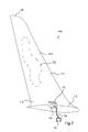
FIGURE 2 is a perspective view of a wing tip device in accordance with the present invention, and; -
FIGURE 3 is a side section view of a wing tip device in accordance with the present invention. - Turning to
Figure 1 , there is provided anaircraft 100 comprising afuselage 102, aleft wing 104 and aright wing 106. Each of thewings wing tip device - The
wing tip devices wing tip device 108 will be described in detail as show inFigures 2 and3 . - The
wing tip device 108 comprises a wing tip attachment formation 110 (not shown inFigure 2 ) which comprises the necessary mechanical formation and attachment means (not described here) for attachment to the end of the tip of thewing 104. - Extending from the
attachment device 110, there is defined a firstwing tip portion 112 extending in substantially a spanwise direction. A secondwing tip portion 114 extends at an angle to the first portion 112 (usually between 50 and 80 degrees thereto and substantially vertically in use) and is connected to thefirst portion 112 via a blendedcurved section 116. Thesecond portion 114 extends to afree end 118 of the wing tip device. - The
first portion 112 comprises anupper surface 120 and an oppositelower surface 122. Similarly, thesecond portion 114 comprises an inward facingsurface 124 which faces thefuselage 102 and an outward facingsurface 126 which faces away from thefuselage 102. - The inward facing
surface 124 defines advertising or alogo 128 which is intended to be visible to the passengers within thefuselage 102. - The
first portion 112 defines a lightingdevice receiving formation 130 comprising a cavity having anelectrical connector 132 installed in a fixed position therein, which electrical connector is connected via acable 134 to theaircraft control systems 136. - The
connector 132 is of a known type and comprises a male or female type connection with an easy-fit formation such as a snap-fit or bayonet type connector. - A
lighting device 138 is provided comprising a self-contained unit having alamp array 140 contained therein and aflat glazing panel 142 installed thereover. The lighting device 178 is insertable into the lightingdevice receiving formation 130. Thelighting device 138 comprises a further connector (not visible) which is configured to engage with theconnector 132 such that power and/or control signals can be delivered to thelamp array 140. - The
lamp array 140 is positioned at an angle suitable for illuminating theface 124 and therefore the advertising orlogo 128. As such, thelamp array 140 may be oriented at an angle of 30 to 70 degrees to the horizontal, thus providing a directed light beam onto thesurface 124. Thelamp array 140 comprises a series of LED lamps. - It will be noted that the
lighting device 138 may be entirely self-contained and may include a separate power supply. More preferably, however, thelighting device 138 makes use of the aircraft's power systems but contains all the necessary electrical equipment to control thelamp array 140. - The
glazing component 142 is arranged to form a flush fit with thefirst portion 112 and, in particular, withsurface 120 such that a smooth aerodynamic surface is maintained across thewing tip device 108 and therefore aerodynamic performance is not detrimentally affected by the presence of thelighting device 138. - The
glazing component 142 is preferably transparent or may be translucent in order to diffuse the light from thelamp array 140 as required. - The
lighting device 138 and the lightingdevice receiving formation 130 are configured so that thedevice 138 is insertable in a single orientation only. As such, upon installation it would be extremely difficult to install the device incorrectly such that thelamp array 140 does not point towards thesurface 124. - The
lamp array 140 may be movable in use by manual or electronic means such that the light beam emitted therefrom may be directed to different parts of thesurface 124 depending on the type of logo oradvertising 128 disposed thereon. - Variations fall within the scope of the present invention.
- As well as being retained in position by the electrical connectors, the
lighting unit 138 may be retained by clips and/or a snap-fit of theglazing component 142 with the surrounding componentry. Alternatively, the glazing may be installed via adhesive or hermetically sealed, or even integrally moulded during the manufacturing process. Thelighting device 138 may also include a heat sink within the winglet to distribute heat away from thelamp array 140. - Preferably the
light lamp array 140 comprises an array of LED light heads to give uniform coverage of the advertising orlogo 128. - As well as being particularly shaped to suit the lamp device receiving formation, the
light device 138 may provide an index formation (for example, a male lug which fits with a female lug within the light device receiving formation 130). - Other light sources may be used instead of an LED, however, LEDs are preferable.
Claims (13)
- A wing tip device comprising:a wing tip attachment formation,a first portion extending from the wing tip attachment formation and configured to extend in a substantially span wise direction in use,a second portion extending to a free end of the wing tip device and configured to extend at a non-zero angle relative to the first portion,a lighting device mounted with the first portion and arranged to project light towards a surface of the second portion.
- A wing tip device according to claim 1, in which the lighting device defines an external surface, which external surface is flush with an external surface of the first portion.
- A wing tip device according to claim 2 in which the lighting device comprises a glazing component arranged to form a substantially uninterrupted aerodynamic surface with the external surface of the first portion.
- A wing tip device according to any preceding claim in which the lighting device comprises a removable module comprising an electrical controller and illumination means.
- A wing tip device according to claim 4 in which the removable module is sealed and comprises a first electrical connector for connection to an electrical supply of an aircraft.
- A wing tip device according to claim 5 in which the first portion of the wing tip defines a module receiving formation comprising a second electrical connector.
- A wing tip device according to claim 6 in which the first and second electrical connectors are fixed.
- A wing tip device according to claim 8 in which the first and second electrical connectors comprise a bayonet, touch or spring loaded contact.
- A wing tip device according to any preceding claim in which the first portion defines a lighting device receiving formation, and in which the lighting device and receiving formation are configured to permit installation of the lighting device in the receiving formation in a single orientation only.
- A wing tip device according to any preceding claim in which the lighting device comprises a directional illumination means, and in which the orientation of the illumination means is adjustable.
- A wing tip device according to claim 10 in which the adjustment is manual.
- A wing tip device according to claim 11 in which the adjustment is via an electrical actuator.
- A wing tip device according to any preceding claim in which the lighting device comprises LEDs.
Applications Claiming Priority (1)
| Application Number | Priority Date | Filing Date | Title |
|---|---|---|---|
| GBGB1115026.5A GB201115026D0 (en) | 2011-08-31 | 2011-08-31 | Aircraft lighting device |
Publications (2)
| Publication Number | Publication Date |
|---|---|
| EP2565118A2 true EP2565118A2 (en) | 2013-03-06 |
| EP2565118A3 EP2565118A3 (en) | 2016-12-07 |
Family
ID=44838971
Family Applications (1)
| Application Number | Title | Priority Date | Filing Date |
|---|---|---|---|
| EP12179023.2A Withdrawn EP2565118A3 (en) | 2011-08-31 | 2012-08-02 | Aircraft lighting device |
Country Status (4)
| Country | Link |
|---|---|
| US (1) | US9090341B2 (en) |
| EP (1) | EP2565118A3 (en) |
| CN (1) | CN102963535B (en) |
| GB (1) | GB201115026D0 (en) |
Cited By (3)
| Publication number | Priority date | Publication date | Assignee | Title |
|---|---|---|---|---|
| GB2553524A (en) * | 2016-09-06 | 2018-03-14 | Airbus Operations Ltd | Wing tip device |
| EP3527498A1 (en) * | 2018-02-16 | 2019-08-21 | Goodrich Lighting Systems GmbH | Aircraft vertical stabilizer illumination light and aircraft comprising the same |
| EP3712702A1 (en) * | 2019-03-22 | 2020-09-23 | The Boeing Company | Display systems and methods |
Families Citing this family (13)
| Publication number | Priority date | Publication date | Assignee | Title |
|---|---|---|---|---|
| USD723678S1 (en) * | 2013-06-17 | 2015-03-03 | Delta T Corporation | Winglet for a ceiling fan |
| USD717936S1 (en) * | 2014-02-27 | 2014-11-18 | Delta T Corporation | Blade tip |
| USD732657S1 (en) * | 2014-02-27 | 2015-06-23 | Delta T Corporation | Winglet |
| FR3020621B1 (en) * | 2014-04-30 | 2016-04-15 | Airbus Corp Jet Centre | LIGHT DEVICE FOR THE INTERIOR PLANNING OF AN AIRCRAFT CABIN |
| US10059461B2 (en) | 2014-10-17 | 2018-08-28 | Saf-T-Glo Limited | Aircraft marking system |
| WO2016181425A1 (en) * | 2015-05-12 | 2016-11-17 | 新明和工業株式会社 | Display system |
| EP3106392B1 (en) * | 2015-06-19 | 2018-06-06 | Goodrich Lighting Systems GmbH | Aircraft vertical stabilizer illumination light unit and method of operating an aircraft vertical stabilizer illumination light unit |
| WO2018109582A1 (en) * | 2016-12-12 | 2018-06-21 | Bombardier Inc. | Aircraft slat |
| GB2572407A (en) * | 2018-03-29 | 2019-10-02 | Airbus Operations Ltd | Aircraft wing lighting |
| EP3584170B1 (en) * | 2018-06-19 | 2021-08-11 | Goodrich Lighting Systems GmbH | Cover for an exterior aircraft light, exterior aircraft light, and method of determining a wear state of a lens cover structure |
| GB2580045A (en) * | 2018-12-20 | 2020-07-15 | Airbus Operations Ltd | Aircraft glazing unit |
| US10780991B1 (en) * | 2019-06-06 | 2020-09-22 | B/E Aerospace, Inc. | Aircraft winglet light assembly |
| EP3998216A4 (en) * | 2019-07-12 | 2022-08-17 | Koito Manufacturing Co., Ltd. | Aircraft lighting unit |
Family Cites Families (24)
| Publication number | Priority date | Publication date | Assignee | Title |
|---|---|---|---|---|
| GB576118A (en) * | 1940-11-22 | 1946-03-20 | Frederick Sidney Cotton | Improvements in or relating to navigation lights for night-flying aircraft |
| US2375075A (en) * | 1941-05-29 | 1945-05-01 | Edgar F Puryear | Running light for airplanes |
| US2832059A (en) * | 1956-05-24 | 1958-04-22 | Jr Charles Adler | External lighting system for airplanes |
| US4205810A (en) * | 1977-12-19 | 1980-06-03 | The Boeing Company | Minimum drag wing configuration for aircraft operating at transonic speeds |
| US4380788A (en) * | 1981-05-11 | 1983-04-19 | The United States Of America As Represented By The Secretary Of The Air Force | Aerial refuel floodlight |
| US4776542A (en) * | 1987-05-27 | 1988-10-11 | Vigyan Research Associates, Inc. | Aircraft stall-spin entry deterrent system |
| US5275358A (en) * | 1991-08-02 | 1994-01-04 | The Boeing Company | Wing/winglet configurations and methods for aircraft |
| US5348253A (en) * | 1993-02-01 | 1994-09-20 | Gratzer Louis B | Blended winglet |
| US5381312A (en) * | 1993-08-04 | 1995-01-10 | Authier; Ricky J. | Aircraft illumination device |
| US5719568A (en) * | 1995-11-28 | 1998-02-17 | Adams; Peter J. | Perimeter light system |
| NO318247B1 (en) * | 1999-12-22 | 2005-02-21 | Advanced Light As | Lighting device for installation on a flat surface |
| US6963293B1 (en) * | 2000-05-11 | 2005-11-08 | Rastar Corporation | System and method of preventing aircraft wingtip ground incursion |
| US6484968B2 (en) * | 2000-12-11 | 2002-11-26 | Fort F. Felker | Aircraft with elliptical winglets |
| US6796533B2 (en) * | 2001-03-26 | 2004-09-28 | Auburn University | Method and apparatus for boundary layer reattachment using piezoelectric synthetic jet actuators |
| US6669357B2 (en) * | 2001-09-26 | 2003-12-30 | The Boeing Company | Surface illumination system of an aircraft and like vehicles |
| US6886778B2 (en) * | 2003-06-30 | 2005-05-03 | The Boeing Company | Efficient wing tip devices and methods for incorporating such devices into existing wing designs |
| FR2860493B1 (en) | 2003-10-06 | 2006-01-13 | Christian Hugues | METHOD FOR INCREASING THE LIGHT SIGNALING IN THE END OF AIRCRAFT WINGS |
| WO2005075288A1 (en) | 2004-02-06 | 2005-08-18 | Koji Yamashita | Airship |
| US7175321B1 (en) * | 2004-03-24 | 2007-02-13 | Lopez Gustavo M | Projector systems |
| US7324016B1 (en) * | 2005-11-22 | 2008-01-29 | The United States Of America As Represented By The Secretary Of The Navy | Navigational indicating system for rotary wing aircraft |
| DE102006055090A1 (en) * | 2006-11-21 | 2008-05-29 | Airbus Deutschland Gmbh | Wing i.e. airfoil wing, end form for wing of commercial aircraft, has transition area arranged between wing and winglet, where local V-form changes continuously from wing to winglet in transition area |
| US20080137353A1 (en) * | 2006-12-08 | 2008-06-12 | Larsen Ty A | Multi-mode exterior lighting architectures for aircraft |
| AU2009290118B2 (en) | 2008-09-02 | 2013-10-24 | Concept Ideas Pty Ltd | Arrangement for illuminating an aircraft fuselage |
| DE102009008084B4 (en) | 2009-02-09 | 2018-04-05 | Airbus Operations Gmbh | Imaging lighting for aircraft interior surfaces |
-
2011
- 2011-08-31 GB GBGB1115026.5A patent/GB201115026D0/en not_active Ceased
-
2012
- 2012-07-30 US US13/561,472 patent/US9090341B2/en active Active
- 2012-08-02 EP EP12179023.2A patent/EP2565118A3/en not_active Withdrawn
- 2012-08-30 CN CN201210315114.6A patent/CN102963535B/en not_active Expired - Fee Related
Non-Patent Citations (1)
| Title |
|---|
| None |
Cited By (6)
| Publication number | Priority date | Publication date | Assignee | Title |
|---|---|---|---|---|
| GB2553524A (en) * | 2016-09-06 | 2018-03-14 | Airbus Operations Ltd | Wing tip device |
| EP3527498A1 (en) * | 2018-02-16 | 2019-08-21 | Goodrich Lighting Systems GmbH | Aircraft vertical stabilizer illumination light and aircraft comprising the same |
| US10730639B2 (en) | 2018-02-16 | 2020-08-04 | Goodrich Lighting Systems Gmbh | Aircraft vertical stabilizer illumination light and aircraft comprising the same |
| EP3712702A1 (en) * | 2019-03-22 | 2020-09-23 | The Boeing Company | Display systems and methods |
| US11492137B2 (en) | 2019-03-22 | 2022-11-08 | The Boeing Company | Display systems and methods |
| EP4520667A3 (en) * | 2019-03-22 | 2025-06-11 | The Boeing Company | Display systems and methods |
Also Published As
| Publication number | Publication date |
|---|---|
| US9090341B2 (en) | 2015-07-28 |
| CN102963535B (en) | 2016-11-23 |
| GB201115026D0 (en) | 2011-10-12 |
| CN102963535A (en) | 2013-03-13 |
| EP2565118A3 (en) | 2016-12-07 |
| US20130048793A1 (en) | 2013-02-28 |
Similar Documents
| Publication | Publication Date | Title |
|---|---|---|
| US9090341B2 (en) | Aircraft lighting device | |
| CN101356858B (en) | Led lighting system | |
| US9080731B2 (en) | Lighting housing with LED illumination insert | |
| US11920766B2 (en) | Adjustable recessed light fixture | |
| US11391424B2 (en) | Lighting apparatus | |
| EP2392511B1 (en) | Aircraft position light assembly | |
| EP1723034A1 (en) | Multi-platform led-based aircraft rear position light | |
| WO2011139768A2 (en) | Linear led light module | |
| US20150055370A1 (en) | Light-emitting diode edge lighted airfield guidance sign | |
| CN202870442U (en) | Lens structure of infrared light source | |
| CN203176856U (en) | Horizontal-plug light-emitting diode (LED) lamp with rotatable lamp body and lamp holder | |
| KR20220024293A (en) | Lamp for vehicle | |
| JP2015018627A (en) | LED lights | |
| EP3266717B1 (en) | A wingtip device, an aircraft having a wingtip device and a method of integrating an aircraft light into a wingtip device | |
| CN109931533B (en) | A kind of ramp indicating lamp component | |
| CN202171925U (en) | Electronic advertisement handle | |
| CN221463747U (en) | Universal starlight lamp | |
| CN207421870U (en) | A kind of light-emitting LED floor lamp up and down | |
| CN205037213U (en) | Train is arc lamps and lanterns for guest room | |
| GB2524108A (en) | Lighting systems | |
| CN219933785U (en) | Multi-dimensional spherical luminous LED lamp | |
| CN205301778U (en) | Directly according to disposable for shooting LED light of formula and sheen formula | |
| GB2623922A (en) | Lighting apparatus with detachable portion | |
| US11926419B2 (en) | Aircraft light and aircraft comprising at least one air-craft light | |
| CN211780409U (en) | LED lamp |
Legal Events
| Date | Code | Title | Description |
|---|---|---|---|
| PUAI | Public reference made under article 153(3) epc to a published international application that has entered the european phase |
Free format text: ORIGINAL CODE: 0009012 |
|
| AK | Designated contracting states |
Kind code of ref document: A2 Designated state(s): AL AT BE BG CH CY CZ DE DK EE ES FI FR GB GR HR HU IE IS IT LI LT LU LV MC MK MT NL NO PL PT RO RS SE SI SK SM TR |
|
| AX | Request for extension of the european patent |
Extension state: BA ME |
|
| PUAL | Search report despatched |
Free format text: ORIGINAL CODE: 0009013 |
|
| AK | Designated contracting states |
Kind code of ref document: A3 Designated state(s): AL AT BE BG CH CY CZ DE DK EE ES FI FR GB GR HR HU IE IS IT LI LT LU LV MC MK MT NL NO PL PT RO RS SE SI SK SM TR |
|
| AX | Request for extension of the european patent |
Extension state: BA ME |
|
| RIC1 | Information provided on ipc code assigned before grant |
Ipc: B64D 47/06 20060101ALI20161102BHEP Ipc: B64D 47/02 20060101ALI20161102BHEP Ipc: B64C 23/06 20060101AFI20161102BHEP |
|
| STAA | Information on the status of an ep patent application or granted ep patent |
Free format text: STATUS: THE APPLICATION HAS BEEN PUBLISHED |
|
| STAA | Information on the status of an ep patent application or granted ep patent |
Free format text: STATUS: THE APPLICATION IS DEEMED TO BE WITHDRAWN |
|
| 18D | Application deemed to be withdrawn |
Effective date: 20170608 |