EP2564979A2 - Bushing to repair circumferential flanged ring - Google Patents
Bushing to repair circumferential flanged ring Download PDFInfo
- Publication number
- EP2564979A2 EP2564979A2 EP12182035A EP12182035A EP2564979A2 EP 2564979 A2 EP2564979 A2 EP 2564979A2 EP 12182035 A EP12182035 A EP 12182035A EP 12182035 A EP12182035 A EP 12182035A EP 2564979 A2 EP2564979 A2 EP 2564979A2
- Authority
- EP
- European Patent Office
- Prior art keywords
- bushing
- circumferential
- flange
- flanged ring
- recited
- Prior art date
- Legal status (The legal status is an assumption and is not a legal conclusion. Google has not performed a legal analysis and makes no representation as to the accuracy of the status listed.)
- Granted
Links
Images


Classifications
-
- B—PERFORMING OPERATIONS; TRANSPORTING
- B23—MACHINE TOOLS; METAL-WORKING NOT OTHERWISE PROVIDED FOR
- B23P—METAL-WORKING NOT OTHERWISE PROVIDED FOR; COMBINED OPERATIONS; UNIVERSAL MACHINE TOOLS
- B23P6/00—Restoring or reconditioning objects
- B23P6/002—Repairing turbine components, e.g. moving or stationary blades, rotors
- B23P6/005—Repairing turbine components, e.g. moving or stationary blades, rotors using only replacement pieces of a particular form
-
- F—MECHANICAL ENGINEERING; LIGHTING; HEATING; WEAPONS; BLASTING
- F01—MACHINES OR ENGINES IN GENERAL; ENGINE PLANTS IN GENERAL; STEAM ENGINES
- F01D—NON-POSITIVE DISPLACEMENT MACHINES OR ENGINES, e.g. STEAM TURBINES
- F01D25/00—Component parts, details, or accessories, not provided for in, or of interest apart from, other groups
- F01D25/16—Arrangement of bearings; Supporting or mounting bearings in casings
- F01D25/162—Bearing supports
- F01D25/164—Flexible supports; Vibration damping means associated with the bearing
-
- F—MECHANICAL ENGINEERING; LIGHTING; HEATING; WEAPONS; BLASTING
- F01—MACHINES OR ENGINES IN GENERAL; ENGINE PLANTS IN GENERAL; STEAM ENGINES
- F01D—NON-POSITIVE DISPLACEMENT MACHINES OR ENGINES, e.g. STEAM TURBINES
- F01D5/00—Blades; Blade-carrying members; Heating, heat-insulating, cooling or antivibration means on the blades or the members
- F01D5/005—Repairing methods or devices
-
- Y—GENERAL TAGGING OF NEW TECHNOLOGICAL DEVELOPMENTS; GENERAL TAGGING OF CROSS-SECTIONAL TECHNOLOGIES SPANNING OVER SEVERAL SECTIONS OF THE IPC; TECHNICAL SUBJECTS COVERED BY FORMER USPC CROSS-REFERENCE ART COLLECTIONS [XRACs] AND DIGESTS
- Y10—TECHNICAL SUBJECTS COVERED BY FORMER USPC
- Y10T—TECHNICAL SUBJECTS COVERED BY FORMER US CLASSIFICATION
- Y10T29/00—Metal working
- Y10T29/49—Method of mechanical manufacture
- Y10T29/49316—Impeller making
- Y10T29/49318—Repairing or disassembling
Definitions
- This application relates generally to a bushing used to restore, repair and create a circumferential flanged ring.
- Gas turbine engines include multiple sections, such as a fan section, a compressor section, a combustor section, a turbine section, and an exhaust section.
- Bearing compartments include bearings, etc., that rotatably support and rotatably couple the components in many of these sections.
- the gas turbine engine also includes several components that are a circumferential flanged ring.
- the static low pressure compressor bearing support includes an end with a smaller circumference including a flange that is attached to a static front bearing support assembly, and an opposing end with a larger circumference including a flange that is attached to a static strut.
- the circumferential flanged ring can be damaged due to cracking. This type of damage can be repaired by welding, plate welding, or plasma welding. However, welding can cause distortion.
- the circumferential flanged ring can also be damaged due to dimensional changes caused by creep, thermal stresses or aging. If this occurs, bolt holes in the flange could misalign with a corresponding component during assembly, making the attachment of the circumferential flanged ring to another component more difficult.
- a method of repairing a circumferential flanged ring of a gas turbine engine with a bushing includes the steps of removing a damaged portion from a flange of a circumferential flanged ring that has an original profile to define a new profile and removing a portion of a bushing to define a bushing profile that matches the new profile of the flange.
- the method further includes the step of attaching the bushing to the flange of the circumferential flanged ring.
- a bushing and circumferential flanged ring assembly of a gas turbine engine includes a circumferential flanged ring and a bushing.
- the circumferential flanged ring includes a flange having an original profile, and a portion is removed to define a new profile.
- the bushing has a bushing profile that matches the new profile of the flange. The flange and the bushing are attached.
- a bushing and circumferential ring assembly of a gas turbine engine includes a plurality of segments attached to form a circumferential ring, the circumferential ring having a first end and an opposing second end.
- the bushing and circumferential ring assembly also includes a circumferential bushing fitted on each of the first end and the second end of the circumferential ring.
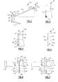
- Figure 1 illustrates a gas turbine engine 10 that is circumferentially disposed about an axis 12.
- the gas turbine engine 10 includes a fan section 14, a low-pressure compressor section 16, a high-pressure compressor section 18, a combustion section 20, a high-pressure turbine section 22, and a low-pressure turbine section 24.
- the high-pressure compressor section 18 and the low-pressure compressor section 16 include rotors 26 and 28, respectively.
- the rotors 26 and 28 are configured to rotate about the axis 12, driving the compressors 16 and 18.
- the compressors 16 and 18 include alternating rows of rotating compressor blades 30 and static airfoils or vanes 32.
- the high-pressure turbine section 22 includes a rotor 34 that is rotatably coupled to the rotor 26, and the low-pressure turbine section 24 includes a rotor 36 that is rotatably coupled to the rotor 28.
- the rotors 34 and 36 are configured to rotate about the axis 12 in response to expansion. When rotated, the rotors 34 and 36 drive the high-pressure compressor section 18 and the low-pressure compressor section 16.
- the rotor 36 also rotatably drives a fan 38 of the fan section 14.
- the turbines 22 and 24 include alternating rows of rotating airfoils or turbine blades 40 and static airfoils or vanes 42.
- the gas turbine engine 10 includes a circumferential flanged ring 44.
- the circumferential flanged ring 44 can be any component of the gas turbine engine 10 that is a bearing support, a case, or a flanged ring that has adequate space or clearance on at least one side to allow for the connection and engagement of a bushing 72, as described below.
- the combination of the bushing 72 and the circumferential flanged ring 44 support the structural requirements of the original undamaged circumferential flanged ring 44.
- the circumferential flanged ring 44 can have the shape of a truncated cone, a cylinder, or be frustoconical in shape (although only a cross-section of a portion of the circumferential flanged ring 44 is shown). In the example show, the circumferential flanged ring 44 has the shape of a truncated cone.
- the circumferential flanged ring 44 is static.
- a first end 46 of the circumferential flanged ring 44 includes a flange 48 having a plurality of bolt holes 50.
- the flange 48 is circumferential in shape, and the plurality of bolt holes 50 are arranged in a circular pattern.
- An opposing second end 52 of the circumferential flanged ring 44 includes another flange 54 (also circumferential in shape) that includes a plurality of bolt holes 56, and the plurality of bolt holes 56 are also arranged in a circular pattern.
- the flange 48 has a smaller diameter than the diameter of the another flange 54.
- a body portion 58 having the shape of truncated cone is defined between the flange 48 and the another flange 54.
- the flange 48 is connected to a static assembly 60 (shown schematically in Figures 1 and 2 ) that includes a plurality of bolt holes 62 that each align with one of the plurality of bolt holes 50, and a bolt 64 is received in each set of the aligned bolt holes 50 and 62.
- the second end 52 is connected to another static assembly 65 (shown schematically in Figures 1 and 2 ) including a plurality of bolt holes 66 that each align with one of the plurality of bolt holes 56, and a bolt 68 is received in each set of the aligned bolt holes 56 and 66.
- the circumferential flanged ring 44 is a low pressure compressor bearing support.
- the static assembly 60 is a static front bearing support assembly, and the another static assembly 65 is a static strut.
- the static front bearing support assembly supports a rotating bearing 108 associated with a rotating shaft 110 of the gas turbine engine 10.
- Figure 2 illustrates the circumferential flanged ring 44 as a low pressure compressor bearing support
- the circumferential flanged ring 44 can be any component of the gas turbine engine 10 that is a bearing support, a case, or a flanged ring that has adequate space on at least one side to allow for the connection of a bushing 72, as described below.
- Figure 3 shows a cross-sectional view of a portion of the flange 48. Portions of the flange 48 are prone to damage. An outer surface of the flange 48 defines an original outer profile 70.
- a bushing 72 that is circumferential in shape (a cross-section of a portion of the bushing 72 is shown in Figure 5 ) is employed to repair a damaged area 74 of the flange 48.
- the flange 48 can crack (which is likely to occur on an inner portion of the flange 48), for example from handling damage, and the axial planes need to be restored.
- an area of the flange 48 needs to be dimensionally restored (which is likely to occur on a face of the flange 48) because of dimensional changes due to creep caused by thermal stresses and/or aging.
- Figure 4 illustrates a cross-sectional view of a portion of the flange 48 after machining.
- the original outer profile 70 of the flange 48 is shown in dashed lines.
- the flange 48 is machined to remove the damaged area 74 or any area that needs to be dimensionally restored to define a new outer profile 76, shown in solid lines.
- the flange 48 is also milled or machined to radially elongate the bolt holes 50 such that each bolt hole 50 has an oval shape and defines a new bolt hole profile 78.
- at least one recess 80 is formed on a top surface 82 of the flange 48.
- a seal groove 84 can be formed on an outer surface 86 of the flange 48.
- the recess 80 and the groove 84 are machined.
- Figure 5 illustrates the bushing 72 that is to be attached to the new outer profile 76 of the flange 48.
- the bushing 72 is machined.
- the outer profile 104 of the bushing 72 is shown in solid lines.
- the bushing 72 is made of the same material as the circumferential flanged ring 44, including the flange 48.
- both the bushing 72 and the circumferential flanged ring 44 are made of an aluminum alloy or a magnesium alloy.
- the bushing 72 and the circumferential flanged ring 44 can also be made of low alloy steel, titanium, nickel, or any other material.
- the bushing 72 and the circumferential flanged ring 44 can also be made from different materials. The matching of thermal expansion must be managed if an alternate material is selected for strength, corrosion resistance or any other reason.
- the bushing 72 is machined such that an inner profile 88 of the bushing 72 matches and corresponds to the new outer profile 76 of the flange 48.
- the bushing 72 includes at least one tab 90 that corresponds in size, shape and location to the at least one recess 80 of the flange 48.
- the at least one recess 80 and the at least one tab 90 lock the bushing 72 to the flange 48 for the purpose of resisting rotational motion between the bushing 72 and flange 48.
- the bushing 72 and the flange 48 can include a plurality of tabs 90 and a plurality of recesses 80, respectively.
- the number of recesses 80 equals the number of tabs 90, and the recesses 80 and the tabs 90 are located to align with each other when the bushing 72 is positioned on the flange 48. In one example, there are two recesses 80 and two tabs 90.
- a seal groove 92 that corresponds in axial and radial placement and size to the seal groove 84 of the flange 48 can also formed on an inner surface 102 of the bushing 72.
- the seal groove 84 is machined.
- the bushing 72 includes a plurality of bolt holes 94 that each align with one of the plurality of bolt holes 50 of the flange 48 (which can now have the new bolt hole profile 78) when the bushing 72 is assembled on the flange 48.
- the bolt holes 94 are circular.
- Each of the plurality of bolt holes 94 have a diameter equal to the original diameter of each of the plurality of bolt holes 50 prior to being radially elongated to have the new bolt hole profile 78.
- the bushing 72 will locate the bolt holes 50 radially. Both the flange 48 and bushing 72 will concurrently locate the holes 50 and 94 circumferentially.
- the bushing 72 is then positioned on the flange 48 of the circumferential flanged ring 44. If the bushing 72 and the circumferential flanged ring 44 includes the at least one tab 90 and the at least one recess 80, respectively, the at least one tab 90 of the bushing 72 is received in the at least one recess 80 of the flange 48 and increases the hoop stiffness of the bushing 72 relative to the flange 48 and provides clocking. An outer diameter defined by the at least one tab 90 is greater than an outer diameter defined by a remainder of the bushing 72 to provide the hoop stiffness.
- An outer diameter defined by the at least one recess 80 of the flange 48 is slightly larger than an inner diameter defined by the at least one tab 90 of the bushing 72, creating a tight interference that retains the flange 48 and the bushing 72 together in this embodiment.
- the new outer profile 76 of the flange 48 contacts the inner profile 88 of the bushing 72 as the profiles 76 and 88 have been machined to match each other.
- a seal 96 for example an o-ring, is located in the aligned seal grooves 84 and 92.
- the seal 96 prevents the bypass of oil and/or air.
- bushing 72 is much larger in size than traditional bushings, there is room for installing the seal 96 between the flange 48 and the bushing 72 to prevent fluid or air leakage.
- the bushing 72 and the flange 48 can be coated with a fluoroelastomer sealant to prevent the bypass of oil and/or air.
- an adhesive agent or anaerobic sealing compound can be employed to bond the bushing 72 and the flange 48 to prevent the bypass of oil and/or air.
- the adhesive agent is Loctite ®, a registered trademark of Henkel Corporation of Rocky Hill, Connecticut. The bushing 72 and the flange 48 are then clamped together until the fluoroelastomer sealant or the adhesive agent are cured.
- the engagement of the at least one tab 90 of the bushing 72 in the at least one recess 80 of the flange 48 provide a strong attachment between the bushing 72 and the flange 48.
- the outer profile 104 of the bushing 72 can be machined to correspond to the original outer profile 70 of the flange 48 and have a new outer profile 106 that matches the original outer profile 70 of the flange 48.
- the at least one tab 90 and the bonding material if any, retain the bushing 72 to the flange 48 of the circumferential flanged ring 44 to prevent separation during assembly and use.
- the hoop stiffness is increased.
- Each of plurality of bolt holes 94 of the bushing 72 are aligned with one of the plurality of bolt holes 50 (in one example, the plurality of bolt holes 50 have the new bolt hole profile 78) of the flange 48.
- the bolt 64 is received in each of the aligned bolt holes 50 and 94 (as well as the bolt hole 62 of the static assembly 60).
- this allows for an easier assembly and installation of the bolts 64 due to the additional clearance 100 created by the radially elongated bolt holes 50 having the new bolt hole profile 78.
- the bushing 72 can be attached to an inner diameter of the flange 48. In this example, there is clearance for the bushing 72 inside the inner diameter of the circumferential flanged ring 44.
- the at least one tab 90 of the bushing 72 has a length that covers an outer diameter of the flange 48. This additional length provides the bushing 72 with anti-rotational features relative to the flange 48.
- the circumferential flanged ring 44 and the bushing 72 do not include the at least one recess 80 and the at least one tab 90, respectively.
- the circumferential flanged ring 44 and the bushing 72 are aligned by the bolts 64 received in the bolt holes 50 and 94 of the circumferential flanged ring 44 and the bushing 72, respectively.
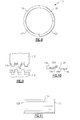
- a circumferential ring assembly 114 has a shape that is not possible to achieve by casting in a single process. Therefore, individual separate segments 116, 118, 120 and 122 are cast and assembled together to form the circumferential ring assembly 114. Although four separate segments 116, 118, 120 and 122 are illustrated and shown, the circumferential ring assembly 114 can include any number of separate segments.
- one segment 116 includes a plurality of protrusions 134 and a plurality of recesses 136 that extend within the material of the segment 116.
- the other segment 118 includes a plurality of protrusions 138 each located to be received in one of the plurality of recesses 136 and a plurality of recesses 140 each located to receive one of the plurality of protrusions 134.
- the protrusions 134 and 138 are each received in one of the recesses 140 and 136, respectively, to retain the segments 116 and 118 together.
- the other segments 120 and 122 are retained in a similar manner.
- the segment 116 includes a projection 164 and a recess 144
- the segment 118 includes a projection 166 and a recess 168.
- the projection 164 of the segment 116 is received in the recess 168 of the segment 118
- the projection 166 of the segment is received in the recess 144 of the segment 118.
- the other segments 120 and 122 are retained in a similar manner.
- circumferential bushings 128 and 130 are be added to both the ends of the circumferential ring assembly 114 to provide hoop stiffness and strength to the plurality of separate segments 116, 118, 120 and 122 that are assembled to form the circumferential ring assembly 114.
- a flange of each of the circumferential ring assembly 114 and the circumferential bushings 128 and 130 are machined and assembled as described above and push outward against the circumferential ring assembly 114.
- Figure 12 illustrates an example segmental circumferential ring assembly 142.
- Circumferential bushings 132 and 174 have a substantial L-cross section including a portion 158 the contacts the circumferential ring assembly 142 and a substantially perpendicular flange 160 (shown in cross-section).
- the portion 158 of each of the circumferential bushings 132 and 174 are attached at the ends of the circumferential ring assembly 142.
- the circumferential bushings 132 and 174 are secured by an interference fit with the circumferential ring assembly 142.
- fasteners 162 for example bolts, can be used to attach the portion 158 to the circumferential ring assembly 142.
- Figure 13 illustrates another example segmental circumferential ring assembly 176 including a circumferential flange 146 and 148 at each of the opposing ends of the circumferential ring assembly 176.
- a circumferential bushing 150 and 152 (shown in cross-section) is attached to each of the circumferential flanges 146 and 148, respectively, and each have a substantial L-cross section.
- Each circumferential bushing 150 and 152 includes a portion 154 that contacts the outermost portion of the circumferential flanges 146 and 148 and a perpendicular portion 170 flush and parallel with the circumferential flanges 146 and 148.
- the circumferential bushings 150 and 152 are secured by an interference fit with the flanges 146 and 148, respectively, of the circumferential ring assembly 176.
Landscapes
- Engineering & Computer Science (AREA)
- Mechanical Engineering (AREA)
- General Engineering & Computer Science (AREA)
- Structures Of Non-Positive Displacement Pumps (AREA)
- Turbine Rotor Nozzle Sealing (AREA)
Abstract


Description
- This application relates generally to a bushing used to restore, repair and create a circumferential flanged ring.
- Gas turbine engines include multiple sections, such as a fan section, a compressor section, a combustor section, a turbine section, and an exhaust section. Bearing compartments include bearings, etc., that rotatably support and rotatably couple the components in many of these sections. The gas turbine engine also includes several components that are a circumferential flanged ring.
- One example circumferential flanged ring is a static low pressure compressor bearing support. The static low pressure compressor bearing support includes an end with a smaller circumference including a flange that is attached to a static front bearing support assembly, and an opposing end with a larger circumference including a flange that is attached to a static strut.
- The circumferential flanged ring can be damaged due to cracking. This type of damage can be repaired by welding, plate welding, or plasma welding. However, welding can cause distortion. The circumferential flanged ring can also be damaged due to dimensional changes caused by creep, thermal stresses or aging. If this occurs, bolt holes in the flange could misalign with a corresponding component during assembly, making the attachment of the circumferential flanged ring to another component more difficult.
- The current practice for a non-serviceable flange made of titanium, steel, cobalt or nickel is to cut off and weld a replacement forging with extra stock to allow machining of the original flange geometry. Certain types of alloys, such as aluminum and magnesium, cannot be easily processed by the welded flange replacement process and cannot be repaired by this method.
- A method of repairing a circumferential flanged ring of a gas turbine engine with a bushing includes the steps of removing a damaged portion from a flange of a circumferential flanged ring that has an original profile to define a new profile and removing a portion of a bushing to define a bushing profile that matches the new profile of the flange. The method further includes the step of attaching the bushing to the flange of the circumferential flanged ring.
- A bushing and circumferential flanged ring assembly of a gas turbine engine includes a circumferential flanged ring and a bushing. The circumferential flanged ring includes a flange having an original profile, and a portion is removed to define a new profile. The bushing has a bushing profile that matches the new profile of the flange. The flange and the bushing are attached.
- A bushing and circumferential ring assembly of a gas turbine engine includes a plurality of segments attached to form a circumferential ring, the circumferential ring having a first end and an opposing second end. The bushing and circumferential ring assembly also includes a circumferential bushing fitted on each of the first end and the second end of the circumferential ring.
- These and other features of the present invention can be best understood from the following specification and drawings, the following of which is a brief description.
-
-
Figure 1 illustrates a simplified cross-sectional view of a standard gas turbine engine; -
Figure 2 illustrates a cross-sectional view of a portion of a circumferential flanged ring; -
Figure 3 illustrates a cross-sectional view of a portion of a circumferential flange of the circumferential flanged ring including a damaged portion; -
Figure 4 illustrates a cross-sectional view of a portion of the flange of the circumferential flanged ring after machining to remove the damaged portion; -
Figure 5 illustrates a cross-sectional view of a portion of a circumferential bushing employed to repair the circumferential flanged ring; -
Figure 6 illustrates a cross-sectional view of the bushing positioned on the circumferential flanged ring; -
Figure 7 illustrates a cross-sectional view of the bushing positioned on the circumferential flanged ring including a longer tab; and -
Figure 8 illustrates a end view of a circumferential ring assembly formed of several segments; -
Figure 9 illustrates one example of a joint between adjacent segments of the circumferential ring assembly formed of several segments; -
Figure 10 illustrates another example of a joint between adjacent segments of the circumferential ring assembly; -
Figure 11 illustrates a schematic circumferential ring assembly including two bushings at opposing ends to provide hoop strength: -
Figure 12 illustrates a circumferential ring assembly with a flanged bushing at opposing ends of the circumferential ring; and -
Figure 13 illustrates a circumferential flanged ring assembly with a flanged bushing at opposing ends of the circumferential ring. -
Figure 1 illustrates agas turbine engine 10 that is circumferentially disposed about an axis 12. Thegas turbine engine 10 includes a fan section 14, a low-pressure compressor section 16, a high-pressure compressor section 18, a combustion section 20, a high-pressure turbine section 22, and a low-pressure turbine section 24. - During operation, air is compressed in the low-pressure compressor section 16 and the high-
pressure compressor section 18. The compressed air is then mixed with fuel and burned in the combustion section 20. The products of combustion are expanded across the high-pressure turbine section 22 and the low-pressure turbine section 24. - The high-
pressure compressor section 18 and the low-pressure compressor section 16 includerotors rotors compressors 16 and 18. Thecompressors 16 and 18 include alternating rows of rotating compressor blades 30 and static airfoils or vanes 32. - The high-pressure turbine section 22 includes a
rotor 34 that is rotatably coupled to therotor 26, and the low-pressure turbine section 24 includes a rotor 36 that is rotatably coupled to therotor 28. Therotors 34 and 36 are configured to rotate about the axis 12 in response to expansion. When rotated, therotors 34 and 36 drive the high-pressure compressor section 18 and the low-pressure compressor section 16. The rotor 36 also rotatably drives a fan 38 of the fan section 14. Theturbines 22 and 24 include alternating rows of rotating airfoils or turbine blades 40 and static airfoils or vanes 42. - As shown in
Figure 2 , thegas turbine engine 10 includes a circumferential flangedring 44. The circumferential flangedring 44 can be any component of thegas turbine engine 10 that is a bearing support, a case, or a flanged ring that has adequate space or clearance on at least one side to allow for the connection and engagement of abushing 72, as described below. The combination of thebushing 72 and the circumferential flangedring 44 support the structural requirements of the original undamaged circumferential flangedring 44. - The circumferential
flanged ring 44 can have the shape of a truncated cone, a cylinder, or be frustoconical in shape (although only a cross-section of a portion of the circumferential flangedring 44 is shown). In the example show, the circumferential flangedring 44 has the shape of a truncated cone. The circumferentialflanged ring 44 is static. In one example, afirst end 46 of the circumferential flangedring 44 includes aflange 48 having a plurality ofbolt holes 50. Theflange 48 is circumferential in shape, and the plurality ofbolt holes 50 are arranged in a circular pattern. An opposingsecond end 52 of the circumferential flangedring 44 includes another flange 54 (also circumferential in shape) that includes a plurality ofbolt holes 56, and the plurality ofbolt holes 56 are also arranged in a circular pattern. Theflange 48 has a smaller diameter than the diameter of theanother flange 54. Abody portion 58 having the shape of truncated cone is defined between theflange 48 and theanother flange 54. - The
flange 48 is connected to a static assembly 60 (shown schematically inFigures 1 and2 ) that includes a plurality ofbolt holes 62 that each align with one of the plurality ofbolt holes 50, and abolt 64 is received in each set of the alignedbolt holes second end 52 is connected to another static assembly 65 (shown schematically inFigures 1 and2 ) including a plurality ofbolt holes 66 that each align with one of the plurality ofbolt holes 56, and abolt 68 is received in each set of the alignedbolt holes - In the example shown in
Figure 2 , the circumferentialflanged ring 44 is a low pressure compressor bearing support. Thestatic assembly 60 is a static front bearing support assembly, and the anotherstatic assembly 65 is a static strut. The static front bearing support assembly supports arotating bearing 108 associated with arotating shaft 110 of thegas turbine engine 10. AlthoughFigure 2 illustrates the circumferentialflanged ring 44 as a low pressure compressor bearing support, the circumferentialflanged ring 44 can be any component of thegas turbine engine 10 that is a bearing support, a case, or a flanged ring that has adequate space on at least one side to allow for the connection of abushing 72, as described below. -
Figure 3 shows a cross-sectional view of a portion of theflange 48. Portions of theflange 48 are prone to damage. An outer surface of theflange 48 defines an originalouter profile 70. Abushing 72 that is circumferential in shape (a cross-section of a portion of thebushing 72 is shown inFigure 5 ) is employed to repair a damagedarea 74 of theflange 48. In one example, theflange 48 can crack (which is likely to occur on an inner portion of the flange 48), for example from handling damage, and the axial planes need to be restored. In another example, an area of theflange 48 needs to be dimensionally restored (which is likely to occur on a face of the flange 48) because of dimensional changes due to creep caused by thermal stresses and/or aging. -
Figure 4 illustrates a cross-sectional view of a portion of theflange 48 after machining. The originalouter profile 70 of theflange 48 is shown in dashed lines. Theflange 48 is machined to remove the damagedarea 74 or any area that needs to be dimensionally restored to define a newouter profile 76, shown in solid lines. - In one example, the
flange 48 is also milled or machined to radially elongate the bolt holes 50 such that eachbolt hole 50 has an oval shape and defines a newbolt hole profile 78. In one example, at least onerecess 80 is formed on atop surface 82 of theflange 48. In one example, aseal groove 84 can be formed on anouter surface 86 of theflange 48. In one example, therecess 80 and thegroove 84 are machined. -
Figure 5 illustrates thebushing 72 that is to be attached to the newouter profile 76 of theflange 48. In one example, thebushing 72 is machined. Theouter profile 104 of thebushing 72 is shown in solid lines. In one example, thebushing 72 is made of the same material as the circumferentialflanged ring 44, including theflange 48. For example, both thebushing 72 and the circumferentialflanged ring 44 are made of an aluminum alloy or a magnesium alloy. Thebushing 72 and the circumferentialflanged ring 44 can also be made of low alloy steel, titanium, nickel, or any other material. Thebushing 72 and the circumferentialflanged ring 44 can also be made from different materials. The matching of thermal expansion must be managed if an alternate material is selected for strength, corrosion resistance or any other reason. Thebushing 72 is machined such that aninner profile 88 of thebushing 72 matches and corresponds to the newouter profile 76 of theflange 48. - In one example, the
bushing 72 includes at least onetab 90 that corresponds in size, shape and location to the at least onerecess 80 of theflange 48. The at least onerecess 80 and the at least onetab 90 lock thebushing 72 to theflange 48 for the purpose of resisting rotational motion between thebushing 72 andflange 48. Thebushing 72 and theflange 48 can include a plurality oftabs 90 and a plurality ofrecesses 80, respectively. The number ofrecesses 80 equals the number oftabs 90, and therecesses 80 and thetabs 90 are located to align with each other when thebushing 72 is positioned on theflange 48. In one example, there are tworecesses 80 and twotabs 90. - A
seal groove 92 that corresponds in axial and radial placement and size to theseal groove 84 of theflange 48 can also formed on aninner surface 102 of thebushing 72. In one example, theseal groove 84 is machined. - The
bushing 72 includes a plurality of bolt holes 94 that each align with one of the plurality of bolt holes 50 of the flange 48 (which can now have the new bolt hole profile 78) when thebushing 72 is assembled on theflange 48. In one example, the bolt holes 94 are circular. Each of the plurality of bolt holes 94 have a diameter equal to the original diameter of each of the plurality of bolt holes 50 prior to being radially elongated to have the newbolt hole profile 78. Thebushing 72 will locate the bolt holes 50 radially. Both theflange 48 andbushing 72 will concurrently locate theholes - As shown in
Figure 6 , thebushing 72 is then positioned on theflange 48 of the circumferentialflanged ring 44. If thebushing 72 and the circumferentialflanged ring 44 includes the at least onetab 90 and the at least onerecess 80, respectively, the at least onetab 90 of thebushing 72 is received in the at least onerecess 80 of theflange 48 and increases the hoop stiffness of thebushing 72 relative to theflange 48 and provides clocking. An outer diameter defined by the at least onetab 90 is greater than an outer diameter defined by a remainder of thebushing 72 to provide the hoop stiffness. An outer diameter defined by the at least onerecess 80 of theflange 48 is slightly larger than an inner diameter defined by the at least onetab 90 of thebushing 72, creating a tight interference that retains theflange 48 and thebushing 72 together in this embodiment. The newouter profile 76 of theflange 48 contacts theinner profile 88 of thebushing 72 as theprofiles - If the
flange 48 and thebushing 72 includeseal grooves seal 96, for example an o-ring, is located in the alignedseal grooves seal 96 prevents the bypass of oil and/or air. Asbushing 72 is much larger in size than traditional bushings, there is room for installing theseal 96 between theflange 48 and thebushing 72 to prevent fluid or air leakage. - Again, as the
bushing 72 is much larger in size than traditional bushings, there is room for a sealing compound at the interface between theflange 48 andbushing 72. In another example, instead ofseal grooves bushing 72 and theflange 48 can be coated with a fluoroelastomer sealant to prevent the bypass of oil and/or air. Alternately, instead ofseal grooves bushing 72 and theflange 48 to prevent the bypass of oil and/or air. In one example, the adhesive agent is Loctite ®, a registered trademark of Henkel Corporation of Rocky Hill, Connecticut. Thebushing 72 and theflange 48 are then clamped together until the fluoroelastomer sealant or the adhesive agent are cured. - Once assembled, the engagement of the at least one
tab 90 of thebushing 72 in the at least onerecess 80 of theflange 48 provide a strong attachment between thebushing 72 and theflange 48. In one example, theouter profile 104 of thebushing 72 can be machined to correspond to the originalouter profile 70 of theflange 48 and have a newouter profile 106 that matches the originalouter profile 70 of theflange 48. The at least onetab 90 and the bonding material, if any, retain thebushing 72 to theflange 48 of the circumferentialflanged ring 44 to prevent separation during assembly and use. By employing thebushing 72, the hoop stiffness is increased. - Each of plurality of bolt holes 94 of the
bushing 72 are aligned with one of the plurality of bolt holes 50 (in one example, the plurality of bolt holes 50 have the new bolt hole profile 78) of theflange 48. Thebolt 64 is received in each of the aligned bolt holes 50 and 94 (as well as thebolt hole 62 of the static assembly 60). In the example where the bolt holes 50 are slightly radially elongated, this allows for an easier assembly and installation of thebolts 64 due to the additional clearance 100 created by the radially elongated bolt holes 50 having the newbolt hole profile 78. Once assembled, the secured parts together carry load in all directions, except for the direction in which the plurality of bolt holes 50 are radially elongated. - In another example, the
bushing 72 can be attached to an inner diameter of theflange 48. In this example, there is clearance for thebushing 72 inside the inner diameter of the circumferentialflanged ring 44. - In another example shown in
Figure 7 , the at least onetab 90 of thebushing 72 has a length that covers an outer diameter of theflange 48. This additional length provides thebushing 72 with anti-rotational features relative to theflange 48. - In another example, the circumferential
flanged ring 44 and thebushing 72 do not include the at least onerecess 80 and the at least onetab 90, respectively. In this example, the circumferentialflanged ring 44 and thebushing 72 are aligned by thebolts 64 received in the bolt holes 50 and 94 of the circumferentialflanged ring 44 and thebushing 72, respectively. - In another example, as shown in
Figure 8 , acircumferential ring assembly 114 has a shape that is not possible to achieve by casting in a single process. Therefore, individualseparate segments circumferential ring assembly 114. Although fourseparate segments circumferential ring assembly 114 can include any number of separate segments. - As shown in
Figures 9 and 10 , theseparate segments Figure 9 , onesegment 116 includes a plurality ofprotrusions 134 and a plurality ofrecesses 136 that extend within the material of thesegment 116. Theother segment 118 includes a plurality ofprotrusions 138 each located to be received in one of the plurality ofrecesses 136 and a plurality ofrecesses 140 each located to receive one of the plurality ofprotrusions 134. Theprotrusions recesses segments other segments - In another example shown in
Figure 10 , thesegment 116 includes aprojection 164 and arecess 144, and thesegment 118 includes aprojection 166 and arecess 168. Theprojection 164 of thesegment 116 is received in therecess 168 of thesegment 118, and theprojection 166 of the segment is received in therecess 144 of thesegment 118. Theother segments - Although the assembly of the
segments circumferential ring assembly 114, the interlocking joints do not provide stiffness, and thesegments Figure 11 ,circumferential bushings circumferential ring assembly 114 to provide hoop stiffness and strength to the plurality ofseparate segments circumferential ring assembly 114. A flange of each of thecircumferential ring assembly 114 and thecircumferential bushings circumferential ring assembly 114. -
Figure 12 illustrates an example segmentalcircumferential ring assembly 142.Circumferential bushings portion 158 the contacts thecircumferential ring assembly 142 and a substantially perpendicular flange 160 (shown in cross-section). Theportion 158 of each of thecircumferential bushings circumferential ring assembly 142. In one example, thecircumferential bushings circumferential ring assembly 142. Additionally,fasteners 162, for example bolts, can be used to attach theportion 158 to thecircumferential ring assembly 142. -
Figure 13 illustrates another example segmentalcircumferential ring assembly 176 including acircumferential flange circumferential ring assembly 176. Acircumferential bushing 150 and 152 (shown in cross-section) is attached to each of thecircumferential flanges circumferential bushing portion 154 that contacts the outermost portion of thecircumferential flanges perpendicular portion 170 flush and parallel with thecircumferential flanges circumferential bushings flanges circumferential ring assembly 176. - The foregoing description is only exemplary of the principles of the invention. Many modifications and variations are possible in light of the above teachings. It is, therefore, to be understood that within the scope of the appended claims, the invention may be practiced otherwise than using the example embodiments which have been specifically described. For that reason the following claims should be studied to determine the true scope and content of this invention.
Claims (15)
- A method of repairing a circumferential flanged ring (44) of a gas turbine engine (10), the method comprising the steps of:removing a damaged portion (74) from a flange (48) of a circumferential flanged ring (44) having an original profile (70) to define a new profile (76);removing a portion of a circumferential bushing (72) to define a bushing profile (88) that matches the new profile (76) of the flange (48); andattaching the bushing (72) to the flange (48) of the circumferential flange ring (44).
- The method as recited in claim 1 including the step of sealing the flange (48) of the circumferential flanged ring (44) relative to the bushing (72).
- The method as recited in claim 1 or 2 wherein the circumferential flanged ring (44) includes a first circumferential flange (48) having a plurality of flange holes (50).
- The method as recited in claim 3 including the steps of forming a plurality of bushing holes (94) having a circular shape in the bushing (72), forming the plurality of flange holes (50) to have an oval shape, aligning each of the plurality of bushing holes (94) with one of the plurality of flange holes (50), and inserting a fastener (64) into the aligned holes (50,94).
- The method as recited in any preceding claim including the steps of forming at least one recess (80) on a top circumferential surface of the flange (48), forming at least one tab (90) on the bushing (72), and locating the at least one tab (90) in the at least one recess (80) to secure the bushing (72) to the flange (48) by an interference fit.
- A bushing and circumferential flanged ring assembly of a gas turbine engine, the bushing and circumferential flanged ring assembly comprising:a circumferential flanged ring (44) including a flange (48) having an original profile (70), wherein a portion (74) is removed to define a new profile (76); anda bushing (72) having bushing profile (88) that matches the new profile (76) of the flange (48), wherein the flange (48)and the bushing are attached.
- The bushing and circumferential flanged ring assembly as recited in claim 6 wherein the circumferential flanged ring (44) is a bearing support of a gas turbine engine.
- The bushing and circumferential flanged ring assembly as recited in claim 6 or 7 wherein the circumferential flanged ring (44) includes a first circumferential flange (48) having a plurality of flange holes (50), and wherein, optionally, the bushing (72) includes a plurality of bushing holes (94) having a circular shape, the plurality of flange holes (50) of the flange (48) have an oval shape, and each of the plurality of bushing holes (94) align with one of the plurality of flange holes (50) to receive a fastener (64).
- The bushing and circumferential flanged ring assembly as recited in claim 6, 7 or 8 wherein at least one recess (80) is formed on a top circumferential surface of the flange (48) of the circumferential flanged ring (44), and the bushing (72) includes at least one tab (90), and the at least one tab (90) is received in the at least one recess (80) to secure the bushing (72) and the circumferential flanged ring (44) by an interference fit.
- The bushing and circumferential flanged ring assembly as recited in any of claims 6 to 9 wherein the bushing (72) and the circumferential flanged ring (44) are made of the same material.
- The bushing and circumferential flanged ring assembly as recited in any of claims 6 to 10 wherein a first circumferential seal groove (84) is formed on an outer surface of the new outer profile (76) of the flange (48), a second circumferential seal groove (92) is formed on an inner surface of the inner profile (88) of the bushing (72), and the first circumferential seal groove (84) and the second circumferential seal groove (92) align to receive a sealing member (96).
- The bushing and circumferential flanged ring assembly as recited in any of claims 6 to 10 wherein one of a flouroelastomer sealant and an adhesive agent is employed to seal the bushing (72) relative to the circumferential flanged ring (44).
- The bushing and circumferential flanged ring assembly as recited in any of claims 6 to 12 wherein the bushing (72) and the circumferential flanged ring (44) are made of an aluminum alloy or a magnesium alloy.
- The bushing and circumferential flanged ring assembly as recited in any of claims 6 to 13 wherein at least one recess is formed on an inner circumferential surface of the flange (48) of the circumferential flanged ring (44), and the bushing (72) includes at least one tab, and the at least one tab is received in the at least one recess to secure the flange and the circumferential flanged ring by an interference fit.
- A bushing and circumferential ring assembly of a gas turbine engine, the bushing and circumferential ring assembly comprising:a plurality of segments (116,118,120,122) attached to form a circumferential ring (114), wherein the circumferential ring (114) has a first end and an opposing second end; anda circumferential bushing (128,130) fitted on each of the first end and the opposing second end of the circumferential ring (114);wherein optionally each of the plurality of segments (116,118,120,122) include a first attachment feature (134,136;164,144) at one end of each of the plurality of segments and a second attachment feature (138,140;166,168) at an opposing end of each of the plurality of segments, and the first attachment feature of one of the plurality of segments attaches to the second attachment feature of another one of the plurality of segments.
Applications Claiming Priority (1)
| Application Number | Priority Date | Filing Date | Title |
|---|---|---|---|
| US13/220,046 US20130051990A1 (en) | 2011-08-29 | 2011-08-29 | Bushing to repair circumferential flanged ring |
Publications (3)
| Publication Number | Publication Date |
|---|---|
| EP2564979A2 true EP2564979A2 (en) | 2013-03-06 |
| EP2564979A3 EP2564979A3 (en) | 2017-01-25 |
| EP2564979B1 EP2564979B1 (en) | 2019-05-29 |
Family
ID=46967973
Family Applications (1)
| Application Number | Title | Priority Date | Filing Date |
|---|---|---|---|
| EP12182035.1A Active EP2564979B1 (en) | 2011-08-29 | 2012-08-28 | Method of repairing a circumferential flanged ring of a gas turbine and bushing and circumferential flanged ring assembly of a gas turbine. |
Country Status (2)
| Country | Link |
|---|---|
| US (1) | US20130051990A1 (en) |
| EP (1) | EP2564979B1 (en) |
Cited By (1)
| Publication number | Priority date | Publication date | Assignee | Title |
|---|---|---|---|---|
| CN103273257A (en) * | 2013-05-30 | 2013-09-04 | 山西航空发动机维修有限责任公司 | Outer lining disassembling method |
Families Citing this family (1)
| Publication number | Priority date | Publication date | Assignee | Title |
|---|---|---|---|---|
| FR3120902B1 (en) * | 2021-03-18 | 2023-03-10 | Safran Aircraft Engines | CENTERING AND GUIDE DEVICE FOR AN AIRCRAFT TURBOMACHINE SHAFT |
Family Cites Families (18)
| Publication number | Priority date | Publication date | Assignee | Title |
|---|---|---|---|---|
| US2391623A (en) * | 1943-12-08 | 1945-12-25 | Armstrong Siddeley Motors Ltd | Bladed rotor |
| DE3037388C1 (en) * | 1980-10-03 | 1982-06-16 | Deutsche Forschungs- und Versuchsanstalt für Luft- und Raumfahrt e.V., 5300 Bonn | Bandage for the radial tensioning of the segments of a compressor impeller for gas turbines constructed from individual segments |
| US5203066A (en) * | 1991-10-18 | 1993-04-20 | Svedala, Inc. | Method of repairing large rotating machines in which parts are bolted together through radially extending flanges |
| US5222295A (en) * | 1992-04-07 | 1993-06-29 | Dorris Jr John W | Method for repairing diesel engine cylinder blocks |
| DE19846475A1 (en) * | 1998-10-09 | 2000-04-13 | Fischer Georg Rohrleitung | Gasket |
| US6082959A (en) * | 1998-12-22 | 2000-07-04 | United Technologies Corporation | Method and apparatus for supporting a rotatable shaft within a gas turbine engine |
| US6273683B1 (en) * | 1999-02-05 | 2001-08-14 | Siemens Westinghouse Power Corporation | Turbine blade platform seal |
| US6517313B2 (en) * | 2001-06-25 | 2003-02-11 | Pratt & Whitney Canada Corp. | Segmented turbine vane support structure |
| US7112036B2 (en) * | 2003-10-28 | 2006-09-26 | Capstone Turbine Corporation | Rotor and bearing system for a turbomachine |
| US7367122B2 (en) * | 2004-10-15 | 2008-05-06 | Honeywell International, Inc. | Stepped sleeve repair of knife seal bores in driven compressor housing |
| US7841834B1 (en) * | 2006-01-27 | 2010-11-30 | Florida Turbine Technologies, Inc. | Method and leading edge replacement insert for repairing a turbine engine blade |
| US9643286B2 (en) * | 2007-04-05 | 2017-05-09 | United Technologies Corporation | Method of repairing a turbine engine component |
| US8257039B2 (en) * | 2008-05-02 | 2012-09-04 | United Technologies Corporation | Gas turbine engine case with replaced flange and method of repairing the same using cold metal transfer |
| US8510926B2 (en) * | 2008-05-05 | 2013-08-20 | United Technologies Corporation | Method for repairing a gas turbine engine component |
| US8245399B2 (en) * | 2009-01-20 | 2012-08-21 | United Technologies Corporation | Replacement of part of engine case with dissimilar material |
| US8230569B2 (en) * | 2009-01-20 | 2012-07-31 | United Technologies Corporation | Repair of case flange with bolt holes |
| FR2956054B1 (en) * | 2010-02-10 | 2012-04-27 | Snecma | METHOD FOR REPAIRING A FLANGE OF A CARTER |
| FR2960463B1 (en) * | 2010-06-01 | 2013-03-29 | Snecma | METHOD FOR REPAIRING A FLANGE OF A CARTER |
-
2011
- 2011-08-29 US US13/220,046 patent/US20130051990A1/en not_active Abandoned
-
2012
- 2012-08-28 EP EP12182035.1A patent/EP2564979B1/en active Active
Non-Patent Citations (1)
| Title |
|---|
| None |
Cited By (1)
| Publication number | Priority date | Publication date | Assignee | Title |
|---|---|---|---|---|
| CN103273257A (en) * | 2013-05-30 | 2013-09-04 | 山西航空发动机维修有限责任公司 | Outer lining disassembling method |
Also Published As
| Publication number | Publication date |
|---|---|
| US20130051990A1 (en) | 2013-02-28 |
| EP2564979B1 (en) | 2019-05-29 |
| EP2564979A3 (en) | 2017-01-25 |
Similar Documents
| Publication | Publication Date | Title |
|---|---|---|
| EP2565380B1 (en) | Hole liners for repair of variable vane shroud counterbore holes | |
| US10180084B2 (en) | Structural case for aircraft gas turbine engine | |
| EP2606204B1 (en) | Inter stage seal housing having a replaceable wear strip | |
| US7618234B2 (en) | Hook ring segment for a compressor vane | |
| US9694440B2 (en) | Support collar geometry for linear friction welding | |
| CN1354066A (en) | Method for repairing curved section of nozzle guide device | |
| EP3026212A1 (en) | Blisk rim face undercut | |
| US20100172761A1 (en) | Method of fabricating a turbomachine compressor drum | |
| CN103917761A (en) | Hot gas expander inlet casing assembly and method | |
| US20090110552A1 (en) | Compressor stator vane repair with pin | |
| JP2017031970A (en) | Compressor patch ring, and method of attaching compressor patch ring | |
| JP5214280B2 (en) | Turbine nozzle segment and repair method thereof | |
| US8347498B2 (en) | Method for repairing a guide vane segment | |
| EP2564979B1 (en) | Method of repairing a circumferential flanged ring of a gas turbine and bushing and circumferential flanged ring assembly of a gas turbine. | |
| US6881032B2 (en) | Exit stator mounting | |
| US9045984B2 (en) | Stator vane mistake proofing | |
| US20200056621A1 (en) | Remanufactured Turbocharger Shaft and Method | |
| CN104067000B (en) | Method for repairing wear marks on a rotor supporting a bypass engine fan |
Legal Events
| Date | Code | Title | Description |
|---|---|---|---|
| PUAI | Public reference made under article 153(3) epc to a published international application that has entered the european phase |
Free format text: ORIGINAL CODE: 0009012 |
|
| AK | Designated contracting states |
Kind code of ref document: A2 Designated state(s): AL AT BE BG CH CY CZ DE DK EE ES FI FR GB GR HR HU IE IS IT LI LT LU LV MC MK MT NL NO PL PT RO RS SE SI SK SM TR |
|
| AX | Request for extension of the european patent |
Extension state: BA ME |
|
| RIC1 | Information provided on ipc code assigned before grant |
Ipc: F01D 25/16 20060101ALI20160907BHEP Ipc: B23P 6/00 20060101AFI20160907BHEP Ipc: F01D 5/00 20060101ALI20160907BHEP |
|
| RAP1 | Party data changed (applicant data changed or rights of an application transferred) |
Owner name: UNITED TECHNOLOGIES CORPORATION |
|
| PUAL | Search report despatched |
Free format text: ORIGINAL CODE: 0009013 |
|
| AK | Designated contracting states |
Kind code of ref document: A3 Designated state(s): AL AT BE BG CH CY CZ DE DK EE ES FI FR GB GR HR HU IE IS IT LI LT LU LV MC MK MT NL NO PL PT RO RS SE SI SK SM TR |
|
| AX | Request for extension of the european patent |
Extension state: BA ME |
|
| RIC1 | Information provided on ipc code assigned before grant |
Ipc: F01D 5/00 20060101ALI20161222BHEP Ipc: F01D 25/16 20060101ALI20161222BHEP Ipc: B23P 6/00 20060101AFI20161222BHEP |
|
| STAA | Information on the status of an ep patent application or granted ep patent |
Free format text: STATUS: REQUEST FOR EXAMINATION WAS MADE |
|
| 17P | Request for examination filed |
Effective date: 20170725 |
|
| RBV | Designated contracting states (corrected) |
Designated state(s): AL AT BE BG CH CY CZ DE DK EE ES FI FR GB GR HR HU IE IS IT LI LT LU LV MC MK MT NL NO PL PT RO RS SE SI SK SM TR |
|
| GRAP | Despatch of communication of intention to grant a patent |
Free format text: ORIGINAL CODE: EPIDOSNIGR1 |
|
| STAA | Information on the status of an ep patent application or granted ep patent |
Free format text: STATUS: GRANT OF PATENT IS INTENDED |
|
| INTG | Intention to grant announced |
Effective date: 20181123 |
|
| GRAS | Grant fee paid |
Free format text: ORIGINAL CODE: EPIDOSNIGR3 |
|
| GRAJ | Information related to disapproval of communication of intention to grant by the applicant or resumption of examination proceedings by the epo deleted |
Free format text: ORIGINAL CODE: EPIDOSDIGR1 |
|
| GRAL | Information related to payment of fee for publishing/printing deleted |
Free format text: ORIGINAL CODE: EPIDOSDIGR3 |
|
| STAA | Information on the status of an ep patent application or granted ep patent |
Free format text: STATUS: REQUEST FOR EXAMINATION WAS MADE |
|
| GRAR | Information related to intention to grant a patent recorded |
Free format text: ORIGINAL CODE: EPIDOSNIGR71 |
|
| STAA | Information on the status of an ep patent application or granted ep patent |
Free format text: STATUS: GRANT OF PATENT IS INTENDED |
|
| GRAA | (expected) grant |
Free format text: ORIGINAL CODE: 0009210 |
|
| STAA | Information on the status of an ep patent application or granted ep patent |
Free format text: STATUS: THE PATENT HAS BEEN GRANTED |
|
| INTG | Intention to grant announced |
Effective date: 20190418 |
|
| AK | Designated contracting states |
Kind code of ref document: B1 Designated state(s): AL AT BE BG CH CY CZ DE DK EE ES FI FR GB GR HR HU IE IS IT LI LT LU LV MC MK MT NL NO PL PT RO RS SE SI SK SM TR |
|
| REG | Reference to a national code |
Ref country code: GB Ref legal event code: FG4D |
|
| REG | Reference to a national code |
Ref country code: CH Ref legal event code: EP |
|
| REG | Reference to a national code |
Ref country code: AT Ref legal event code: REF Ref document number: 1137993 Country of ref document: AT Kind code of ref document: T Effective date: 20190615 |
|
| REG | Reference to a national code |
Ref country code: DE Ref legal event code: R096 Ref document number: 602012060548 Country of ref document: DE |
|
| REG | Reference to a national code |
Ref country code: IE Ref legal event code: FG4D |
|
| REG | Reference to a national code |
Ref country code: NL Ref legal event code: MP Effective date: 20190529 |
|
| REG | Reference to a national code |
Ref country code: LT Ref legal event code: MG4D |
|
| PG25 | Lapsed in a contracting state [announced via postgrant information from national office to epo] |
Ref country code: ES Free format text: LAPSE BECAUSE OF FAILURE TO SUBMIT A TRANSLATION OF THE DESCRIPTION OR TO PAY THE FEE WITHIN THE PRESCRIBED TIME-LIMIT Effective date: 20190529 Ref country code: PT Free format text: LAPSE BECAUSE OF FAILURE TO SUBMIT A TRANSLATION OF THE DESCRIPTION OR TO PAY THE FEE WITHIN THE PRESCRIBED TIME-LIMIT Effective date: 20190930 Ref country code: HR Free format text: LAPSE BECAUSE OF FAILURE TO SUBMIT A TRANSLATION OF THE DESCRIPTION OR TO PAY THE FEE WITHIN THE PRESCRIBED TIME-LIMIT Effective date: 20190529 Ref country code: SE Free format text: LAPSE BECAUSE OF FAILURE TO SUBMIT A TRANSLATION OF THE DESCRIPTION OR TO PAY THE FEE WITHIN THE PRESCRIBED TIME-LIMIT Effective date: 20190529 Ref country code: AL Free format text: LAPSE BECAUSE OF FAILURE TO SUBMIT A TRANSLATION OF THE DESCRIPTION OR TO PAY THE FEE WITHIN THE PRESCRIBED TIME-LIMIT Effective date: 20190529 Ref country code: NO Free format text: LAPSE BECAUSE OF FAILURE TO SUBMIT A TRANSLATION OF THE DESCRIPTION OR TO PAY THE FEE WITHIN THE PRESCRIBED TIME-LIMIT Effective date: 20190829 Ref country code: FI Free format text: LAPSE BECAUSE OF FAILURE TO SUBMIT A TRANSLATION OF THE DESCRIPTION OR TO PAY THE FEE WITHIN THE PRESCRIBED TIME-LIMIT Effective date: 20190529 Ref country code: LT Free format text: LAPSE BECAUSE OF FAILURE TO SUBMIT A TRANSLATION OF THE DESCRIPTION OR TO PAY THE FEE WITHIN THE PRESCRIBED TIME-LIMIT Effective date: 20190529 |
|
| PG25 | Lapsed in a contracting state [announced via postgrant information from national office to epo] |
Ref country code: RS Free format text: LAPSE BECAUSE OF FAILURE TO SUBMIT A TRANSLATION OF THE DESCRIPTION OR TO PAY THE FEE WITHIN THE PRESCRIBED TIME-LIMIT Effective date: 20190529 Ref country code: LV Free format text: LAPSE BECAUSE OF FAILURE TO SUBMIT A TRANSLATION OF THE DESCRIPTION OR TO PAY THE FEE WITHIN THE PRESCRIBED TIME-LIMIT Effective date: 20190529 Ref country code: BG Free format text: LAPSE BECAUSE OF FAILURE TO SUBMIT A TRANSLATION OF THE DESCRIPTION OR TO PAY THE FEE WITHIN THE PRESCRIBED TIME-LIMIT Effective date: 20190829 Ref country code: GR Free format text: LAPSE BECAUSE OF FAILURE TO SUBMIT A TRANSLATION OF THE DESCRIPTION OR TO PAY THE FEE WITHIN THE PRESCRIBED TIME-LIMIT Effective date: 20190830 |
|
| REG | Reference to a national code |
Ref country code: AT Ref legal event code: MK05 Ref document number: 1137993 Country of ref document: AT Kind code of ref document: T Effective date: 20190529 |
|
| PG25 | Lapsed in a contracting state [announced via postgrant information from national office to epo] |
Ref country code: AT Free format text: LAPSE BECAUSE OF FAILURE TO SUBMIT A TRANSLATION OF THE DESCRIPTION OR TO PAY THE FEE WITHIN THE PRESCRIBED TIME-LIMIT Effective date: 20190529 Ref country code: EE Free format text: LAPSE BECAUSE OF FAILURE TO SUBMIT A TRANSLATION OF THE DESCRIPTION OR TO PAY THE FEE WITHIN THE PRESCRIBED TIME-LIMIT Effective date: 20190529 Ref country code: DK Free format text: LAPSE BECAUSE OF FAILURE TO SUBMIT A TRANSLATION OF THE DESCRIPTION OR TO PAY THE FEE WITHIN THE PRESCRIBED TIME-LIMIT Effective date: 20190529 Ref country code: RO Free format text: LAPSE BECAUSE OF FAILURE TO SUBMIT A TRANSLATION OF THE DESCRIPTION OR TO PAY THE FEE WITHIN THE PRESCRIBED TIME-LIMIT Effective date: 20190529 Ref country code: SK Free format text: LAPSE BECAUSE OF FAILURE TO SUBMIT A TRANSLATION OF THE DESCRIPTION OR TO PAY THE FEE WITHIN THE PRESCRIBED TIME-LIMIT Effective date: 20190529 Ref country code: CZ Free format text: LAPSE BECAUSE OF FAILURE TO SUBMIT A TRANSLATION OF THE DESCRIPTION OR TO PAY THE FEE WITHIN THE PRESCRIBED TIME-LIMIT Effective date: 20190529 Ref country code: NL Free format text: LAPSE BECAUSE OF FAILURE TO SUBMIT A TRANSLATION OF THE DESCRIPTION OR TO PAY THE FEE WITHIN THE PRESCRIBED TIME-LIMIT Effective date: 20190529 |
|
| PG25 | Lapsed in a contracting state [announced via postgrant information from national office to epo] |
Ref country code: SM Free format text: LAPSE BECAUSE OF FAILURE TO SUBMIT A TRANSLATION OF THE DESCRIPTION OR TO PAY THE FEE WITHIN THE PRESCRIBED TIME-LIMIT Effective date: 20190529 Ref country code: IT Free format text: LAPSE BECAUSE OF FAILURE TO SUBMIT A TRANSLATION OF THE DESCRIPTION OR TO PAY THE FEE WITHIN THE PRESCRIBED TIME-LIMIT Effective date: 20190529 |
|
| REG | Reference to a national code |
Ref country code: DE Ref legal event code: R097 Ref document number: 602012060548 Country of ref document: DE |
|
| PG25 | Lapsed in a contracting state [announced via postgrant information from national office to epo] |
Ref country code: TR Free format text: LAPSE BECAUSE OF FAILURE TO SUBMIT A TRANSLATION OF THE DESCRIPTION OR TO PAY THE FEE WITHIN THE PRESCRIBED TIME-LIMIT Effective date: 20190529 |
|
| PLBE | No opposition filed within time limit |
Free format text: ORIGINAL CODE: 0009261 |
|
| STAA | Information on the status of an ep patent application or granted ep patent |
Free format text: STATUS: NO OPPOSITION FILED WITHIN TIME LIMIT |
|
| PG25 | Lapsed in a contracting state [announced via postgrant information from national office to epo] |
Ref country code: PL Free format text: LAPSE BECAUSE OF FAILURE TO SUBMIT A TRANSLATION OF THE DESCRIPTION OR TO PAY THE FEE WITHIN THE PRESCRIBED TIME-LIMIT Effective date: 20190529 |
|
| 26N | No opposition filed |
Effective date: 20200303 |
|
| PG25 | Lapsed in a contracting state [announced via postgrant information from national office to epo] |
Ref country code: CH Free format text: LAPSE BECAUSE OF NON-PAYMENT OF DUE FEES Effective date: 20190831 Ref country code: MC Free format text: LAPSE BECAUSE OF FAILURE TO SUBMIT A TRANSLATION OF THE DESCRIPTION OR TO PAY THE FEE WITHIN THE PRESCRIBED TIME-LIMIT Effective date: 20190529 Ref country code: LI Free format text: LAPSE BECAUSE OF NON-PAYMENT OF DUE FEES Effective date: 20190831 Ref country code: SI Free format text: LAPSE BECAUSE OF FAILURE TO SUBMIT A TRANSLATION OF THE DESCRIPTION OR TO PAY THE FEE WITHIN THE PRESCRIBED TIME-LIMIT Effective date: 20190529 Ref country code: LU Free format text: LAPSE BECAUSE OF NON-PAYMENT OF DUE FEES Effective date: 20190828 |
|
| REG | Reference to a national code |
Ref country code: BE Ref legal event code: MM Effective date: 20190831 |
|
| PG25 | Lapsed in a contracting state [announced via postgrant information from national office to epo] |
Ref country code: IE Free format text: LAPSE BECAUSE OF NON-PAYMENT OF DUE FEES Effective date: 20190828 |
|
| PG25 | Lapsed in a contracting state [announced via postgrant information from national office to epo] |
Ref country code: BE Free format text: LAPSE BECAUSE OF NON-PAYMENT OF DUE FEES Effective date: 20190831 |
|
| PG25 | Lapsed in a contracting state [announced via postgrant information from national office to epo] |
Ref country code: CY Free format text: LAPSE BECAUSE OF FAILURE TO SUBMIT A TRANSLATION OF THE DESCRIPTION OR TO PAY THE FEE WITHIN THE PRESCRIBED TIME-LIMIT Effective date: 20190529 |
|
| PG25 | Lapsed in a contracting state [announced via postgrant information from national office to epo] |
Ref country code: IS Free format text: LAPSE BECAUSE OF FAILURE TO SUBMIT A TRANSLATION OF THE DESCRIPTION OR TO PAY THE FEE WITHIN THE PRESCRIBED TIME-LIMIT Effective date: 20190929 |
|
| PG25 | Lapsed in a contracting state [announced via postgrant information from national office to epo] |
Ref country code: MT Free format text: LAPSE BECAUSE OF FAILURE TO SUBMIT A TRANSLATION OF THE DESCRIPTION OR TO PAY THE FEE WITHIN THE PRESCRIBED TIME-LIMIT Effective date: 20190529 Ref country code: HU Free format text: LAPSE BECAUSE OF FAILURE TO SUBMIT A TRANSLATION OF THE DESCRIPTION OR TO PAY THE FEE WITHIN THE PRESCRIBED TIME-LIMIT; INVALID AB INITIO Effective date: 20120828 |
|
| PG25 | Lapsed in a contracting state [announced via postgrant information from national office to epo] |
Ref country code: MK Free format text: LAPSE BECAUSE OF FAILURE TO SUBMIT A TRANSLATION OF THE DESCRIPTION OR TO PAY THE FEE WITHIN THE PRESCRIBED TIME-LIMIT Effective date: 20190529 |
|
| REG | Reference to a national code |
Ref country code: DE Ref legal event code: R081 Ref document number: 602012060548 Country of ref document: DE Owner name: RAYTHEON TECHNOLOGIES CORPORATION (N.D.GES.D.S, US Free format text: FORMER OWNER: UNITED TECHNOLOGIES CORPORATION, FARMINGTON, CONN., US Ref country code: DE Ref legal event code: R081 Ref document number: 602012060548 Country of ref document: DE Owner name: RTX CORPORATION (N.D.GES.D. STAATES DELAWARE),, US Free format text: FORMER OWNER: UNITED TECHNOLOGIES CORPORATION, FARMINGTON, CONN., US |
|
| P01 | Opt-out of the competence of the unified patent court (upc) registered |
Effective date: 20230520 |
|
| PGFP | Annual fee paid to national office [announced via postgrant information from national office to epo] |
Ref country code: DE Payment date: 20250724 Year of fee payment: 14 |
|
| PGFP | Annual fee paid to national office [announced via postgrant information from national office to epo] |
Ref country code: GB Payment date: 20250725 Year of fee payment: 14 |
|
| PGFP | Annual fee paid to national office [announced via postgrant information from national office to epo] |
Ref country code: FR Payment date: 20250723 Year of fee payment: 14 |
|
| REG | Reference to a national code |
Ref country code: DE Ref legal event code: R081 Ref document number: 602012060548 Country of ref document: DE Owner name: RTX CORPORATION (N.D.GES.D. STAATES DELAWARE),, US Free format text: FORMER OWNER: RAYTHEON TECHNOLOGIES CORPORATION (N.D.GES.D.STAATES DELAWARE), ARLINGTON, VA, US |