EP2564916A1 - Systems and methods for using a boehmite bond-coat with polyimide membranes for gas separation - Google Patents
Systems and methods for using a boehmite bond-coat with polyimide membranes for gas separation Download PDFInfo
- Publication number
- EP2564916A1 EP2564916A1 EP12181251A EP12181251A EP2564916A1 EP 2564916 A1 EP2564916 A1 EP 2564916A1 EP 12181251 A EP12181251 A EP 12181251A EP 12181251 A EP12181251 A EP 12181251A EP 2564916 A1 EP2564916 A1 EP 2564916A1
- Authority
- EP
- European Patent Office
- Prior art keywords
- layer
- membrane
- gas separation
- approximately
- bond
- Prior art date
- Legal status (The legal status is an assumption and is not a legal conclusion. Google has not performed a legal analysis and makes no representation as to the accuracy of the status listed.)
- Withdrawn
Links
- 239000012528 membrane Substances 0.000 title claims abstract description 174
- 238000000926 separation method Methods 0.000 title claims abstract description 81
- 229920001721 polyimide Polymers 0.000 title claims abstract description 63
- 239000004642 Polyimide Substances 0.000 title claims abstract description 62
- 229910001593 boehmite Inorganic materials 0.000 title claims abstract description 48
- 238000000034 method Methods 0.000 title claims description 24
- 239000002105 nanoparticle Substances 0.000 claims abstract description 48
- FAHBNUUHRFUEAI-UHFFFAOYSA-M hydroxidooxidoaluminium Chemical compound O[Al]=O FAHBNUUHRFUEAI-UHFFFAOYSA-M 0.000 claims abstract description 45
- 239000000758 substrate Substances 0.000 claims abstract description 20
- 239000007789 gas Substances 0.000 claims description 98
- CURLTUGMZLYLDI-UHFFFAOYSA-N Carbon dioxide Chemical compound O=C=O CURLTUGMZLYLDI-UHFFFAOYSA-N 0.000 claims description 25
- 239000002243 precursor Substances 0.000 claims description 23
- 229910052739 hydrogen Inorganic materials 0.000 claims description 19
- 239000001257 hydrogen Substances 0.000 claims description 19
- 229920005575 poly(amic acid) Polymers 0.000 claims description 17
- 229910002092 carbon dioxide Inorganic materials 0.000 claims description 15
- UFHFLCQGNIYNRP-UHFFFAOYSA-N Hydrogen Chemical compound [H][H] UFHFLCQGNIYNRP-UHFFFAOYSA-N 0.000 claims description 14
- 238000000151 deposition Methods 0.000 claims description 14
- 239000011148 porous material Substances 0.000 claims description 13
- 238000004528 spin coating Methods 0.000 claims description 12
- 239000001569 carbon dioxide Substances 0.000 claims description 10
- 238000004519 manufacturing process Methods 0.000 claims description 10
- 238000007669 thermal treatment Methods 0.000 claims description 8
- 239000000919 ceramic Substances 0.000 claims description 6
- 238000003618 dip coating Methods 0.000 claims description 6
- 238000003672 processing method Methods 0.000 claims description 6
- 238000005507 spraying Methods 0.000 claims description 4
- 239000002245 particle Substances 0.000 claims description 3
- PNEYBMLMFCGWSK-UHFFFAOYSA-N aluminium oxide Inorganic materials [O-2].[O-2].[O-2].[Al+3].[Al+3] PNEYBMLMFCGWSK-UHFFFAOYSA-N 0.000 description 25
- 229920005597 polymer membrane Polymers 0.000 description 18
- 239000000203 mixture Substances 0.000 description 13
- 239000000463 material Substances 0.000 description 7
- 125000002887 hydroxy group Chemical group [H]O* 0.000 description 6
- 230000003993 interaction Effects 0.000 description 6
- 239000002002 slurry Substances 0.000 description 6
- 230000015572 biosynthetic process Effects 0.000 description 5
- 230000008021 deposition Effects 0.000 description 5
- LFQSCWFLJHTTHZ-UHFFFAOYSA-N Ethanol Chemical compound CCO LFQSCWFLJHTTHZ-UHFFFAOYSA-N 0.000 description 4
- VYPSYNLAJGMNEJ-UHFFFAOYSA-N Silicium dioxide Chemical compound O=[Si]=O VYPSYNLAJGMNEJ-UHFFFAOYSA-N 0.000 description 4
- 150000002431 hydrogen Chemical class 0.000 description 4
- LYCAIKOWRPUZTN-UHFFFAOYSA-N Ethylene glycol Chemical compound OCCO LYCAIKOWRPUZTN-UHFFFAOYSA-N 0.000 description 3
- 239000011230 binding agent Substances 0.000 description 3
- 230000007547 defect Effects 0.000 description 3
- 239000011521 glass Substances 0.000 description 3
- 239000004014 plasticizer Substances 0.000 description 3
- 229920000642 polymer Polymers 0.000 description 3
- 239000000843 powder Substances 0.000 description 3
- XLYOFNOQVPJJNP-UHFFFAOYSA-N water Substances O XLYOFNOQVPJJNP-UHFFFAOYSA-N 0.000 description 3
- LRHPLDYGYMQRHN-UHFFFAOYSA-N N-Butanol Chemical compound CCCCO LRHPLDYGYMQRHN-UHFFFAOYSA-N 0.000 description 2
- SECXISVLQFMRJM-UHFFFAOYSA-N N-Methylpyrrolidone Chemical compound CN1CCCC1=O SECXISVLQFMRJM-UHFFFAOYSA-N 0.000 description 2
- GRYLNZFGIOXLOG-UHFFFAOYSA-N Nitric acid Chemical compound O[N+]([O-])=O GRYLNZFGIOXLOG-UHFFFAOYSA-N 0.000 description 2
- MCMNRKCIXSYSNV-UHFFFAOYSA-N Zirconium dioxide Chemical compound O=[Zr]=O MCMNRKCIXSYSNV-UHFFFAOYSA-N 0.000 description 2
- 238000001816 cooling Methods 0.000 description 2
- 238000005137 deposition process Methods 0.000 description 2
- 239000002270 dispersing agent Substances 0.000 description 2
- 238000001035 drying Methods 0.000 description 2
- 238000010438 heat treatment Methods 0.000 description 2
- 229910017604 nitric acid Inorganic materials 0.000 description 2
- 239000000047 product Substances 0.000 description 2
- 239000000377 silicon dioxide Substances 0.000 description 2
- 238000005245 sintering Methods 0.000 description 2
- 239000011877 solvent mixture Substances 0.000 description 2
- 239000000126 substance Substances 0.000 description 2
- 239000008096 xylene Substances 0.000 description 2
- 150000003738 xylenes Chemical class 0.000 description 2
- 230000003213 activating effect Effects 0.000 description 1
- WNROFYMDJYEPJX-UHFFFAOYSA-K aluminium hydroxide Chemical compound [OH-].[OH-].[OH-].[Al+3] WNROFYMDJYEPJX-UHFFFAOYSA-K 0.000 description 1
- 239000012298 atmosphere Substances 0.000 description 1
- 238000006243 chemical reaction Methods 0.000 description 1
- 230000006835 compression Effects 0.000 description 1
- 238000007906 compression Methods 0.000 description 1
- 238000007872 degassing Methods 0.000 description 1
- 239000008367 deionised water Substances 0.000 description 1
- 229910021641 deionized water Inorganic materials 0.000 description 1
- 238000010586 diagram Methods 0.000 description 1
- 230000000694 effects Effects 0.000 description 1
- 230000002708 enhancing effect Effects 0.000 description 1
- 150000002148 esters Chemical class 0.000 description 1
- 238000001914 filtration Methods 0.000 description 1
- 230000006870 function Effects 0.000 description 1
- 229910052500 inorganic mineral Inorganic materials 0.000 description 1
- 238000003801 milling Methods 0.000 description 1
- 239000011707 mineral Substances 0.000 description 1
- TWNQGVIAIRXVLR-UHFFFAOYSA-N oxo(oxoalumanyloxy)alumane Chemical compound O=[Al]O[Al]=O TWNQGVIAIRXVLR-UHFFFAOYSA-N 0.000 description 1
- 230000000704 physical effect Effects 0.000 description 1
- 229920002037 poly(vinyl butyral) polymer Polymers 0.000 description 1
- 229920001296 polysiloxane Polymers 0.000 description 1
- 229920006395 saturated elastomer Polymers 0.000 description 1
- 238000001778 solid-state sintering Methods 0.000 description 1
- 239000002904 solvent Substances 0.000 description 1
- 238000009987 spinning Methods 0.000 description 1
- 229910001220 stainless steel Inorganic materials 0.000 description 1
- 239000010935 stainless steel Substances 0.000 description 1
- 238000003756 stirring Methods 0.000 description 1
- 239000006228 supernatant Substances 0.000 description 1
- 230000003746 surface roughness Effects 0.000 description 1
- 238000003786 synthesis reaction Methods 0.000 description 1
- WOZZOSDBXABUFO-UHFFFAOYSA-N tri(butan-2-yloxy)alumane Chemical compound [Al+3].CCC(C)[O-].CCC(C)[O-].CCC(C)[O-] WOZZOSDBXABUFO-UHFFFAOYSA-N 0.000 description 1
Images
Classifications
-
- B—PERFORMING OPERATIONS; TRANSPORTING
- B01—PHYSICAL OR CHEMICAL PROCESSES OR APPARATUS IN GENERAL
- B01D—SEPARATION
- B01D53/00—Separation of gases or vapours; Recovering vapours of volatile solvents from gases; Chemical or biological purification of waste gases, e.g. engine exhaust gases, smoke, fumes, flue gases, aerosols
- B01D53/22—Separation of gases or vapours; Recovering vapours of volatile solvents from gases; Chemical or biological purification of waste gases, e.g. engine exhaust gases, smoke, fumes, flue gases, aerosols by diffusion
- B01D53/228—Separation of gases or vapours; Recovering vapours of volatile solvents from gases; Chemical or biological purification of waste gases, e.g. engine exhaust gases, smoke, fumes, flue gases, aerosols by diffusion characterised by specific membranes
-
- B—PERFORMING OPERATIONS; TRANSPORTING
- B01—PHYSICAL OR CHEMICAL PROCESSES OR APPARATUS IN GENERAL
- B01D—SEPARATION
- B01D69/00—Semi-permeable membranes for separation processes or apparatus characterised by their form, structure or properties; Manufacturing processes specially adapted therefor
- B01D69/10—Supported membranes; Membrane supports
- B01D69/105—Support pretreatment
-
- B—PERFORMING OPERATIONS; TRANSPORTING
- B01—PHYSICAL OR CHEMICAL PROCESSES OR APPARATUS IN GENERAL
- B01D—SEPARATION
- B01D71/00—Semi-permeable membranes for separation processes or apparatus characterised by the material; Manufacturing processes specially adapted therefor
- B01D71/06—Organic material
- B01D71/58—Other polymers having nitrogen in the main chain, with or without oxygen or carbon only
- B01D71/62—Polycondensates having nitrogen-containing heterocyclic rings in the main chain
- B01D71/64—Polyimides; Polyamide-imides; Polyester-imides; Polyamide acids or similar polyimide precursors
Definitions
- the subject matter disclosed herein relates to gas separation membranes and, more specifically, to polyimide gas separation membranes.
- a gas separation membrane relies upon a partial pressure differential across a porous membrane material to selectively drive gas molecules across the membrane.
- the membrane should have a sufficiently high permeance and high selectivity. Permeance is a measure of how easily a particular gas flows across the membrane, while selectivity is a measure of how much more of one component of the gas mixture (e.g., hydrogen) crosses the membrane compared to a second component of the gas mixture (e.g., carbon dioxide).
- one component of the gas mixture e.g., hydrogen
- a second component of the gas mixture e.g., carbon dioxide
- a gas separation membrane includes a porous substrate, a substantially continuous polyimide membrane layer, and one or more layers of boehmite nanoparticles disposed between the porous substrate and the polyimide membrane layer to form a bond-coat layer.
- the bond-coat layer is configured to improve the adhesion of the polyimide membrane layer to the porous substrate, and the polyimide membrane layer has a thickness approximately 100 nm or less.
- a method of manufacturing a gas separation membrane includes depositing one or more layers of boehmite nanoparticles onto a porous support structure to form a bond-coat layer, and depositing a polyimide precursor onto the bond-coat layer. The method further includes performing a thermal treatment of the bond-coat layer and the polyimide precursor at 300 °C or less to form a polyimide membrane layer, wherein the polyimide membrane layer has a thickness approximately 150 nm or less.
- a membrane for gas separation in another embodiment, includes a support layer.
- the membrane also includes an intermediate layer disposed on top of the support layer and providing a surface having a pore size less than 40 nm and having a thickness between approximately 50 and 400 nm.
- the membrane also includes a bond-coat layer comprising boehmite nanoparticles disposed on top of the intermediate layer and having a thickness between approximately 50 nm and 400 nm.
- the membrane further includes a polyimide membrane disposed on top of the bond-coat layer having a thickness between 20 and 150 nm.
- a gas separation membrane may include a membrane layer deposited on top of one or more porous support layers in order to provide a high permeance membrane.
- the adhesion of the membrane layer to the underlying porous support layer in the gas separation membrane may be limited, which may lead to membrane failures during manufacturing and use.
- the disclosed embodiments address the aforementioned issues by incorporating a boehmite nanoparticle bond-coat layer to improve the adhesion between the top membrane layer precursor solution and the underlying support layers during the manufacturing process. That is, the boehmite bond-coat enables a greater degree of covalent and/or non-covalent interactions between the precursor solution and the underlying support layers, improving the adhesion between the layers. As such, through the use of this bond-coat, the present gas membrane embodiments illustrate the synthesis and use of thinner membrane layers than previously demonstrated, further enhancing the permeance of the membrane.
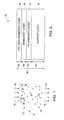
- FIG. 1 illustrates an embodiment of a gas separation membrane 10 being used to separate a gas mixture.
- the gas separation membrane 10 may be used to separate the product gas mixture (e.g., hydrogen and carbon dioxide) from a water-gas shift reactor.
- a partial pressure differential exists across the membrane 10. That is, the pressure on the top side 12 of the membrane in the illustrated embodiment may be significantly higher than the pressure on the bottom side 14 of the membrane. This pressure differential may cause a flow 16 of gas molecules across the membrane.
- the gas mixture present on the top side 12 of the membrane 10 may include hydrogen 18 and carbon dioxide 20 components, and the pressure differential across the membrane 10 may cause a portion of the gas mixture to enter the membrane 10. Furthermore, the partial pressure differential may cause a portion of the gas mixture that enters the gas separation membrane to completely cross the membrane 10.
- the embodiment of FIG. 1 illustrates that, while a portion of both hydrogen 18 and carbon dioxide 20 gases may enter the gas separation membrane 10, only hydrogen 18 gas is illustrated as completely crossing the membrane 10 to reach the other side 14.
- FIG. 1 illustrates an ideal gas separation membrane 10 having perfect selectivity for hydrogen 18 in the presence of carbon dioxide 20.
- gas separation membranes may reduce selectivity in order to improve permeance.
- a relatively thick gas separation membrane may have high selectivity but may suffer from low permeance (i.e., only one species in the gas mixture substantially passes through the membrane, albeit slowly).
- the permeance of the gas separation membrane may generally improve by thinning the membrane.
- membrane defects may become numerous, resulting in a membrane having high permeance and little to no selectivity (i.e., a high flow rate and all species pass through the membrane with relative ease).
- polymer membrane layers may be deposited on top of a porous support structure so that the membrane layer may be thinner than may be mechanically stable for a membrane layer alone. That is, a porous support structure may mechanically support a membrane that would be too thin (e.g., tens to hundreds of nanometers) to support itself.
- the support structure may be any porous material, such as any ceramic (e.g., alumina or silica) or metallic substrate. In certain embodiments, the support structure may have a pore size of less than approximately 40 nm.
- the membrane layer of the gas separation membrane should be adhered securely to the porous support structure in order for the gas separation membrane to properly function. That is, a significant amount of bonding (e.g., covalent bonds or non-covalent interactions) is desirable between the membrane layer and the underlying support structure such that the membrane is substantially immobilized. If, for example, the membrane layer does not properly adhere to the surface of the porous support structure, then the membrane layer may be inadvertently removed during the membrane deposition process, as discussed in detail below. By further example, if the membrane layer does not properly adhere to the surface of the porous support structure, then the membrane layer may be completely or partially removed (e.g., blown out) by the pressure differential and gas flow experienced by the gas separation membrane during the gas separation process.
- a significant amount of bonding e.g., covalent bonds or non-covalent interactions
- a suitable ceramic support structure material is alumina.
- Alumina is a form of aluminum oxide that is used as a porous support for various applications.
- Certain types of alumina layers, such as alpha alumina layers, may be formed though the use of a binding agent and plasticizer in combination with alumina powder, as described below with respect to manufacturing an embodiment of a support layer.
- Other types of alumina layers, such as gamma alumina layers, may be formed by sintering layers of boehmite nanoparticles, as described below with respect to manufacturing an embodiment of an intermediate layer.
- boehmite nanoparticles are nanoparticles of an aluminum hydroxide mineral and, therefore, the surface of the boehmite nanoparticles includes a number of hydroxyl groups.
- the boehmite nanoparticles may release water and fuse to form a gamma alumina layer.
- alpha alumina and gamma alumina may afford slight differences in terms of physical properties (e.g., surface roughness or porosity) such that the materials may serve different roles within different layers of the gas separation membrane.
- FIG. 2 illustrates a side-view of an embodiment of a gas separation membrane 30.
- the illustrated gas separation membrane 30 embodiment includes a support layer 32, an intermediate layer 34, a bond-coat layer 36, and a membrane layer 38.
- support layer is used herein to identify the specific support layer 32
- support structure is used herein to refer to all of the layers located beneath the membrane layer 38 (e.g., support layer 32, intermediate layer 34, and bond-coat 36).
- gas separation membrane refers to the entire structure (e.g., gas separation membrane 30), including the support structure and the membrane layer 38, while the term “membrane layer” is used herein to refer specifically to the membrane layer 38 of the gas separation membrane 30.
- the bottom layer of the illustrated gas separation membrane 30 is the support layer 32.
- the support layer 32 is responsible for providing the mechanical strength of the membrane so as to provide a stable platform for the layers above.
- the support layer 32 may be a porous ceramic or metallic substrate having a pore size greater than approximately 30 nm. It should be noted that pore size, as used herein, refers to the average diameter of the substrate pores.
- the support layer 32 may include an alumina (e.g., alpha alumina) support material and may be manufactured from an alumina slurry, as described in detail below. The porous support layer 32 may occupy the largest portion of the total thickness 40 of the membrane 30.
- the support layer 32 may have a thickness 42 greater than 0.1 mm. In certain embodiments, the support layer 32 may have a thickness 42 approximately between 0.01 mm and 1 mm, 0.05 mm and 5 mm, or 0.1 mm and 0.3 mm. In an embodiment, the thickness 42 of the support layer 32 may be approximately 0.2 mm.
- the intermediate layer 34 may be located.
- the intermediate layer 34 affords a finer porosity and fills defects in the surface of the underlying support layer 32 to provide a smoother surface for later depositions.
- the intermediate layer 34 may be absent from the structure of the gas separation membrane.
- the intermediate layer 34 may include a porous alumina (e.g., gamma alumina) material.
- the intermediate layer 34 may be manufactured using sintered layers of boehmite nanoparticles, as described in detail below.
- the intermediate layer 34 may provide a surface having a pore size less than approximately 40 nm. In certain embodiments, the intermediate layer 34 has a thickness 44 approximately between 50 nm and 500 nm, 100 nm and 400 nm, or 150 nm and 250 nm. In an embodiment, the intermediate layer 34 may have a thickness 44 of approximately 200 nm.
- the bond-coat layer 36 may substantially consist of layers of boehmite nanoparticles.
- the bond-coat layer 36 may serve to improve the adhesion of the polymer membrane layer 38 to the remainder of the support structure. That is, the aforementioned hydroxyl groups on the surface of the boehmite nanoparticles may interact with the remainder of the support structure and the polymer membrane layer 38 (e.g., covalently, non-covalently, or any combination thereof) to improve the adhesion of the polymer membrane layer 38 to the remainder of the support structure, as will be discussed in greater detail below.
- the bond-coat layer 36 may be manufactured by depositing a solution of boehmite nanoparticles, as described in detail below.
- the bond-coat layer 36 may have a thickness 46 approximately between 50 nm and 200 nm, 70 nm and 150 nm, or 60 nm and 100 nm. In an embodiment, the bond-coat layer 36 may have a thickness 46 of approximately 80 nm.
- the final layer of the gas separation membrane 30 is the polymer membrane layer 38.
- the polymer membrane layer 38 may be the limiting factor for the permeance of the gas separation membrane while providing most, if not all, of the selectivity of the gas separation membrane 30. That is, in the absence of the polymer membrane layer 38, the remaining support structure would likely exhibit higher permeance and little to no selectivity.
- the polymer membrane layer 38 may be any polyimide polymer that may be used for gas separation applications.
- the polymer membrane 38 may be substantially continuous and/or defect-free over areas as large as the pore size of the underlying intermediate layer 34 (e.g., 40 nm) and larger.
- the polymer membrane layer 38 may be formed on the surface of a support structure by depositing a solution containing one or more polyimide precursors (e.g., polyamic acid) onto the surface and thermally activating the one or more precursors to bond to yield the polymer membrane layer 38.
- the polymer membrane layer 38 may have a thickness 48 between approximately 10 nm and 200 nm, 15 nm and 150 nm, or 20 nm to 125 nm. In an embodiment, the polymer membrane layer 38 may have a thickness 48 of approximately 30 nm.
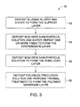
- FIG. 3 depicts one example of a process 50 by which an embodiment of the gas separation membrane 30 may be manufactured.
- the process 50 may begin with depositing (block 52) an alumina slurry and drying the slurry to form the support layer 32.
- a 500 mL NalgeneTM bottle may be charged with 240 g of alumina powder, such as the TM-DARTM 99.99% pure alumina powder available from TaimeiTM, and a 120 g of a 1 to 4 ethanol : xylenes solvent mixture.
- a 2.43 g of dispersant such as the PS-236 PhospholanTM dispersant available from Akzo Nobel, and zirconia milling media (e.g., 5 mm).
- the mixture may be milled for approximately 14.5 hrs.
- binder such as the Butvar ® B-76TM binder available from SolutiaTM
- 83 g of the ethanol : xylenes solvent mixture may be added, and the contents may be milled for approximately 2 hrs.
- the 86.4 g of the contents of the second container may be added to the contents of the 500 mL bottle, along with 24.0 g of a plasticizer, such as the Paraplex ® G-50TM plasticizer available from Hall-StarTM.
- the combined contents may be subsequently milled for another 3 hrs, followed by filtration of the slurry and degassing of the slurry under vacuum.
- the resulting degassed slurry may be tape cast onto a MylarTM-coated glass plate using a doctor blade height of 25 mil and a pull rate of approximately 4 ft/min.
- the MylarTM-coated glass plates may be transferred to a drying cabinet to dry. Once dry, the tape-cast support layer 32 may be removed from the MylarTM-coated glass plate and cut to the appropriate dimensions.
- the cut films may then be thermally treated at 300 °C for 2 hrs to remove the organics and then at 1200 °C for 1 hr to sinter the alumina particles.
- a solution of boehmite nanoparticles may be used in the following steps (e.g., blocks 54 and 56) of the process 50 (e.g., the formation of the intermediate layer 34 and/or the bond-coat layer 36).
- the boehmite nanoparticles solution may be manufactured using the following procedure as an example. To a 2 L three-neck round-bottom flask, 630 mL of water (e.g., 18 Mohm deionized water) may be added. To an addition funnel, 82 mL of aluminum sec -butoxide may be added under inert atmosphere, and the addition funnel may be subsequently coupled to the flask.
- the contents of the addition funnel may then be added dropwise to the contents of the flask at room temperature over approximately 30 min with regular stirring (e.g., approximately 400 rpm). Then, the addition funnel may be removed, a condenser may be added to the flask, and the flask may be introduced into a heating bath (e.g., an oil bath or an ethylene glycol bath). The heating bath may then be warmed to approximately 83-86 °C, and approximately 75 mL of butanol may be distilled from the flask under vacuum. After turning off the heat, 15 mL of a 2 N nitric acid solution (e.g., prepared from ACS PlusTM 15.8 N Nitric Acid available from Fisher ScientificTM) may be added.
- a 2 N nitric acid solution e.g., prepared from ACS PlusTM 15.8 N Nitric Acid available from Fisher ScientificTM
- the solution may be allowed to age for approximately 20 hrs at approximately 90 - 105 °C before being centrifuged for approximately 2 hrs at approximately 2300 rpm and then the supernatant is filtered through a 450 nm filter.
- the product is the boehmite nanoparticles solution, which includes boehmite nanoparticles ranging from approximately 40 nm to 60 nm in diameter.
- the boehmite solution may be used to form the intermediate layer 34 of the gas separation membrane.
- the boehmite nanoparticles solution may be deposited (block 54) onto the surface of the support layer 32 using a wet processing method (e.g., spin-coating or dip-coating), and the deposited nanoparticles may be sintered to form a continuous layer.
- a wet processing method e.g., spin-coating or dip-coating
- the support layer 32 may be placed in a spin-coating machine and the boehmite nanoparticles solution may be added dropwise until the surface is completely covered.
- the spin-coating machine may then be spun up to 4000 rpm for 40 sec.
- the resulting thickness of the bond-coat layer may be controlled by adjusting the concentration of the boehmite nanoparticles solution.
- the deposited nanoparticles layer may then be sintered, or thermally treated, using a temperature ramp of 1 °C/min up to 600 °C, where the temperature may be maintained for approximately 3 hrs before cooling.
- the deposition of the boehmite nanoparticles and the sintering process may be repeated one or more times (e.g., 2 to 5 times) to form a gamma alumina intermediate layer 32, which may serve to smooth defects in the surface of the support layer 32.
- the intermediate layer 34 may not be present and, therefore, this step (e.g., block 54) may be skipped in such embodiments.
- the bond-coat layer 36 may be added to the support structure (e.g., the intermediate layer 34 or the support layer 32).
- the boehmite nanoparticles solution may be deposited (block 56) onto the surface of the support structure using a wet processing method (e.g., spin-coating,dip-coating, or spray-coating).
- a wet processing method e.g., spin-coating,dip-coating, or spray-coating.
- the support structure may be placed in a spin-coating machine and the boehmite nanoparticles solution may be added dropwise until the surface is completely covered.
- the spin-coating machine may then be spun up to 4000 rpm for 40 sec.
- the resulting thickness of the bond-coat layer may be controlled by adjusting the concentration of the boehmite nanoparticles solution.
- the deposited boehmite nanoparticles are not sintered after deposition to convert the nanoparticles to gamma alumina.
- the boehmite nanoparticles continue to express a substantial number of hydroxyl groups on the nanoparticle surfaces throughout the bond coat layer 36.
- a polyimide precursor solution (e.g., a poly(amic acid) solution) may be deposited (block 58) on top of the bond-coat layer 36 and may be thermally treated to form the polymer membrane layer 58.
- a 1 to 2 weight percent solution containing polyamic acid such as the VTECTM 080 051 polyimide precursor available from RBITM
- a solvent such as N-methylpyrrolidone (NMP)
- NMP N-methylpyrrolidone
- the support structure having the bond-coat layer 36 on top may be introduced into a spin-coating machine and the polyamic acid solution may be added dropwise until the surface is saturated. The sample may then be spun up to 6000 rpm for 4 min.
- the resulting thickness of the polyimide membrane layer 38 may be controlled by adjusting the concentration of the polyimide precursor solution.
- the presence of the bond-coat layer 36 may be advantageous during the deposition of the polyimide precursor onto the surface. That is, the aforementioned hydroxyl groups present on the surface of the boehmite nanoparticles may form chemical interactions (e.g., covalent and/or non-covalent bonding) with the polyamic acid molecules, securing a greater number of polyamic acid molecules to the surface.
- the surface hydroxyl groups of the boehmite nanoparticles may form hydrogen bonding networks that secure a substantial amount of polyimide precursor to the surface so that it may not be removed by the centrifugal force of the spin-coating machine.
- boehmite nanoparticles bond-coat layer 36 In the absence of the boehmite nanoparticles bond-coat layer 36, a greater amount of polyamic acid may be removed upon spinning the sample, which may decrease the potential to form a continuous polyimide film during the subsequent thermal treatment process. As such, by securing the polyamic acid molecules to the surface, the presence of the boehmite nanoparticles bond-coat layer 36 enables the formation of thinner polyimide membrane layers 38 than might otherwise be possible.
- the deposited polyamic acid may subsequently be thermally treated (block 58) to form the polyimide polymer layer 38.
- the sample may be placed within a furnace and gradually heated to a 200 - 300 °C.
- the sample may be heated according to the following temperature program: a 10 °C/min temperature ramp from room temperature (e.g., approximately 25 °C) to 50 °C and then hold for 3 hrs; a 10 °C/min temperature ramp from 50 °C to 150 °C and then hold for 6 hrs; a 10 °C/min temperature ramp from 150 °C to 250 °C and then hold for 12 hrs; and a -10 °C/min temperature ramp from 250 °C to 150 °C and then hold for 3 hrs before cooling to room temperature.
- the polyamic acid precursor may substantially be converted to a generally continuous polyimide membrane layer 38.
- the thermal treatment of the polyamic acid polyimide precursor deposited on top of the bond-coat layer 36 may enable further chemical interactions between the resulting polymer membrane layer 38 and the underlying support structure. That is, beyond the hydrogen bonding interactions described above, the hydroxyl groups on the surface of the boehmite nanoparticles of the bond-coat layer 36 may react with the polyamic acid during the thermal imidization reaction in which the polyimide membrane is formed (e.g., through the formation of one or more ester linkages). Once attached, these polymer chains may remain bound (e.g., covalently bonded) to the surface of the boehmite nanoparticles as the polymer membrane 38 is being formed.
- the surface chemistry of the bond-coat layer 36 substantially improves the adhesion of the resulting polymer membrane layer 38 to the underlying support structure as compared to implementations where the bond-coat 36 may be absent.
- a membrane structure may consist of an alpha alumina support layer, a gamma alumina intermediate layer, a boehmite bond coat layer, and a polyimide membrane layer.
- a gas separation membrane may, for example, be mounted between two gaskets (e.g., 1/16" thick silicone gaskets) and placed in a compression fitting (e.g., stainless steel) for use.
- the polyimide membrane side of the gas separation membrane may be exposed to, for example, a 50:50 mixture of H 2 and CO 2 at a certain pressure and temperature (e.g., 10 psid and 250 °C).
- a certain pressure and temperature e.g. 10 psid and 250 °C.
- the H 2 and CO 2 permeances as well as the H 2 /CO 2 selectivity may be determined by analyzing the composition of the gas that has crossed the membrane.
- the hydrogen permeances of the gas separation membrane may range between 250 GPU and 500 GPU or 300 GPU and 400 GPU (where 1 GPU equals 3.347 x10 -10 mol/Pa ⁇ m 2 ⁇ s). In certain embodiments, the hydrogen permeance may be greater than about 350 GPU. Additionally, in certain embodiments the H 2 /CO 2 selectivity of the gas separation membranes may be between 4 and 10. In certain embodiments, the H 2 /CO 2 selectivity may be greater than about 5.
- a bond-coat layer 36 substantially improves the adhesion of the polyamic acid precursor molecules and/or the resulting polyimide polymer membrane 38 to the underlying support structure. By improving this adhesion, thinner polyimide layers may be achieved that are relatively defect-free, at least over the pore size of the underlying support structure. Since the permeance of the gas separation membrane is affected by the thickness of the membrane layer, the inclusion of the bond-coat layer allows for the production of gas separation membranes having relatively higher permeance while still maintaining relatively high selectivity. That is, the current disclosure enables the production of a gas separation membrane having a high permeance for a particular gas (e.g., hydrogen gas) while maintaining a low permeance for another gas (e.g., carbon dioxide).
- a particular gas e.g., hydrogen gas
- another gas e.g., carbon dioxide
Landscapes
- Chemical & Material Sciences (AREA)
- Chemical Kinetics & Catalysis (AREA)
- Engineering & Computer Science (AREA)
- Analytical Chemistry (AREA)
- General Chemical & Material Sciences (AREA)
- Oil, Petroleum & Natural Gas (AREA)
- Separation Using Semi-Permeable Membranes (AREA)
Abstract
Description
- The subject matter disclosed herein relates to gas separation membranes and, more specifically, to polyimide gas separation membranes.
- One method of purifying a gas mixture is through the use of a gas separation membrane. In general, a gas separation membrane relies upon a partial pressure differential across a porous membrane material to selectively drive gas molecules across the membrane. For a gas separation membrane to be effective, the membrane should have a sufficiently high permeance and high selectivity. Permeance is a measure of how easily a particular gas flows across the membrane, while selectivity is a measure of how much more of one component of the gas mixture (e.g., hydrogen) crosses the membrane compared to a second component of the gas mixture (e.g., carbon dioxide). Generally, as the permeance of a membrane increases, the selectivity of the membrane is reduced, making a selective membrane with a high throughput difficult to achieve.
- In an embodiment, a gas separation membrane includes a porous substrate, a substantially continuous polyimide membrane layer, and one or more layers of boehmite nanoparticles disposed between the porous substrate and the polyimide membrane layer to form a bond-coat layer. The bond-coat layer is configured to improve the adhesion of the polyimide membrane layer to the porous substrate, and the polyimide membrane layer has a thickness approximately 100 nm or less.
- In another embodiment, a method of manufacturing a gas separation membrane includes depositing one or more layers of boehmite nanoparticles onto a porous support structure to form a bond-coat layer, and depositing a polyimide precursor onto the bond-coat layer. The method further includes performing a thermal treatment of the bond-coat layer and the polyimide precursor at 300 °C or less to form a polyimide membrane layer, wherein the polyimide membrane layer has a thickness approximately 150 nm or less.
- In another embodiment, a membrane for gas separation includes a support layer. The membrane also includes an intermediate layer disposed on top of the support layer and providing a surface having a pore size less than 40 nm and having a thickness between approximately 50 and 400 nm. The membrane also includes a bond-coat layer comprising boehmite nanoparticles disposed on top of the intermediate layer and having a thickness between approximately 50 nm and 400 nm. The membrane further includes a polyimide membrane disposed on top of the bond-coat layer having a thickness between 20 and 150 nm.
- These and other features, aspects, and advantages of the present invention will become better understood when the following detailed description is read with reference to the accompanying drawings in which like characters represent like parts throughout the drawings, wherein:
-
FIG. 1 is an illustration of an embodiment of a gas separation membrane; -
FIG. 2 is a side view illustrating the various layers of an embodiment of a gas separation membrane; and -
FIG. 3 is a flow diagram illustrating an embodiment of a process to manufacture the gas separation membrane. - It is generally desirable to maximize both the permeance and the selectivity of gas separation membranes in pursuit of membranes that are able to quickly and selectively isolate a particular component of a mixed gas flow. A gas separation membrane may include a membrane layer deposited on top of one or more porous support layers in order to provide a high permeance membrane. However, the adhesion of the membrane layer to the underlying porous support layer in the gas separation membrane may be limited, which may lead to membrane failures during manufacturing and use.
- Accordingly, the disclosed embodiments address the aforementioned issues by incorporating a boehmite nanoparticle bond-coat layer to improve the adhesion between the top membrane layer precursor solution and the underlying support layers during the manufacturing process. That is, the boehmite bond-coat enables a greater degree of covalent and/or non-covalent interactions between the precursor solution and the underlying support layers, improving the adhesion between the layers. As such, through the use of this bond-coat, the present gas membrane embodiments illustrate the synthesis and use of thinner membrane layers than previously demonstrated, further enhancing the permeance of the membrane.
- With the foregoing in mind,
FIG. 1 illustrates an embodiment of agas separation membrane 10 being used to separate a gas mixture. For example, thegas separation membrane 10 may be used to separate the product gas mixture (e.g., hydrogen and carbon dioxide) from a water-gas shift reactor. In the illustrated embodiment, a partial pressure differential exists across themembrane 10. That is, the pressure on thetop side 12 of the membrane in the illustrated embodiment may be significantly higher than the pressure on thebottom side 14 of the membrane. This pressure differential may cause aflow 16 of gas molecules across the membrane. - For example, the gas mixture present on the
top side 12 of themembrane 10 may includehydrogen 18 andcarbon dioxide 20 components, and the pressure differential across themembrane 10 may cause a portion of the gas mixture to enter themembrane 10. Furthermore, the partial pressure differential may cause a portion of the gas mixture that enters the gas separation membrane to completely cross themembrane 10. For example, the embodiment ofFIG. 1 illustrates that, while a portion of bothhydrogen 18 andcarbon dioxide 20 gases may enter thegas separation membrane 10, onlyhydrogen 18 gas is illustrated as completely crossing themembrane 10 to reach theother side 14. - As such,
FIG. 1 illustrates an idealgas separation membrane 10 having perfect selectivity forhydrogen 18 in the presence ofcarbon dioxide 20. In general, gas separation membranes may reduce selectivity in order to improve permeance. For example, a relatively thick gas separation membrane may have high selectivity but may suffer from low permeance (i.e., only one species in the gas mixture substantially passes through the membrane, albeit slowly). As such, the permeance of the gas separation membrane may generally improve by thinning the membrane. However, below a certain thickness membrane defects may become numerous, resulting in a membrane having high permeance and little to no selectivity (i.e., a high flow rate and all species pass through the membrane with relative ease). - Accordingly, polymer membrane layers may be deposited on top of a porous support structure so that the membrane layer may be thinner than may be mechanically stable for a membrane layer alone. That is, a porous support structure may mechanically support a membrane that would be too thin (e.g., tens to hundreds of nanometers) to support itself. The support structure may be any porous material, such as any ceramic (e.g., alumina or silica) or metallic substrate. In certain embodiments, the support structure may have a pore size of less than approximately 40 nm.
- However, the membrane layer of the gas separation membrane should be adhered securely to the porous support structure in order for the gas separation membrane to properly function. That is, a significant amount of bonding (e.g., covalent bonds or non-covalent interactions) is desirable between the membrane layer and the underlying support structure such that the membrane is substantially immobilized. If, for example, the membrane layer does not properly adhere to the surface of the porous support structure, then the membrane layer may be inadvertently removed during the membrane deposition process, as discussed in detail below. By further example, if the membrane layer does not properly adhere to the surface of the porous support structure, then the membrane layer may be completely or partially removed (e.g., blown out) by the pressure differential and gas flow experienced by the gas separation membrane during the gas separation process.
- One example of a suitable ceramic support structure material is alumina. Alumina is a form of aluminum oxide that is used as a porous support for various applications. Certain types of alumina layers, such as alpha alumina layers, may be formed though the use of a binding agent and plasticizer in combination with alumina powder, as described below with respect to manufacturing an embodiment of a support layer. Other types of alumina layers, such as gamma alumina layers, may be formed by sintering layers of boehmite nanoparticles, as described below with respect to manufacturing an embodiment of an intermediate layer. Generally speaking, boehmite nanoparticles are nanoparticles of an aluminum hydroxide mineral and, therefore, the surface of the boehmite nanoparticles includes a number of hydroxyl groups. When a deposited layer of boehmite nanoparticles is sintered (i.e., solid-state sintering) the boehmite nanoparticles may release water and fuse to form a gamma alumina layer. In general, alpha alumina and gamma alumina may afford slight differences in terms of physical properties (e.g., surface roughness or porosity) such that the materials may serve different roles within different layers of the gas separation membrane.
- With the foregoing in mind,
FIG. 2 illustrates a side-view of an embodiment of agas separation membrane 30. The illustratedgas separation membrane 30 embodiment includes asupport layer 32, anintermediate layer 34, a bond-coat layer 36, and a membrane layer 38. It should be noted that the term "support layer" is used herein to identify thespecific support layer 32, while the term "support structure" is used herein to refer to all of the layers located beneath the membrane layer 38 (e.g.,support layer 32,intermediate layer 34, and bond-coat 36). Similarly, the term "gas separation membrane" as used herein refers to the entire structure (e.g., gas separation membrane 30), including the support structure and the membrane layer 38, while the term "membrane layer" is used herein to refer specifically to the membrane layer 38 of thegas separation membrane 30. - The bottom layer of the illustrated
gas separation membrane 30 is thesupport layer 32. In general, thesupport layer 32 is responsible for providing the mechanical strength of the membrane so as to provide a stable platform for the layers above. In certain embodiments, thesupport layer 32 may be a porous ceramic or metallic substrate having a pore size greater than approximately 30 nm. It should be noted that pore size, as used herein, refers to the average diameter of the substrate pores. In certain embodiments, thesupport layer 32 may include an alumina (e.g., alpha alumina) support material and may be manufactured from an alumina slurry, as described in detail below. Theporous support layer 32 may occupy the largest portion of thetotal thickness 40 of themembrane 30. In certain embodiments, thesupport layer 32 may have athickness 42 greater than 0.1 mm. In certain embodiments, thesupport layer 32 may have athickness 42 approximately between 0.01 mm and 1 mm, 0.05 mm and 5 mm, or 0.1 mm and 0.3 mm. In an embodiment, thethickness 42 of thesupport layer 32 may be approximately 0.2 mm. - On top of the
support layer 32 in thegas separation membrane 30 theintermediate layer 34 may be located. In general, theintermediate layer 34 affords a finer porosity and fills defects in the surface of theunderlying support layer 32 to provide a smoother surface for later depositions. As such, in certain embodiments (e.g.,membranes 30 that employ materials that provide a relatively smooth and defect-free support layer 32), theintermediate layer 34 may be absent from the structure of the gas separation membrane. In certain embodiments, theintermediate layer 34 may include a porous alumina (e.g., gamma alumina) material. Theintermediate layer 34 may be manufactured using sintered layers of boehmite nanoparticles, as described in detail below. In certain embodiments, theintermediate layer 34 may provide a surface having a pore size less than approximately 40 nm. In certain embodiments, theintermediate layer 34 has athickness 44 approximately between 50 nm and 500 nm, 100 nm and 400 nm, or 150 nm and 250 nm. In an embodiment, theintermediate layer 34 may have athickness 44 of approximately 200 nm. - The next layer in the
gas separation membrane 30 is the bond-coat layer 36. The bond-coat layer 36 may substantially consist of layers of boehmite nanoparticles. In general, the bond-coat layer 36 may serve to improve the adhesion of the polymer membrane layer 38 to the remainder of the support structure. That is, the aforementioned hydroxyl groups on the surface of the boehmite nanoparticles may interact with the remainder of the support structure and the polymer membrane layer 38 (e.g., covalently, non-covalently, or any combination thereof) to improve the adhesion of the polymer membrane layer 38 to the remainder of the support structure, as will be discussed in greater detail below. The bond-coat layer 36 may be manufactured by depositing a solution of boehmite nanoparticles, as described in detail below. In certain embodiments, the bond-coat layer 36 may have athickness 46 approximately between 50 nm and 200 nm, 70 nm and 150 nm, or 60 nm and 100 nm. In an embodiment, the bond-coat layer 36 may have athickness 46 of approximately 80 nm. - The final layer of the
gas separation membrane 30 is the polymer membrane layer 38. In general, the polymer membrane layer 38 may be the limiting factor for the permeance of the gas separation membrane while providing most, if not all, of the selectivity of thegas separation membrane 30. That is, in the absence of the polymer membrane layer 38, the remaining support structure would likely exhibit higher permeance and little to no selectivity. Accordingly, the polymer membrane layer 38 may be any polyimide polymer that may be used for gas separation applications. Furthermore, the polymer membrane 38 may be substantially continuous and/or defect-free over areas as large as the pore size of the underlying intermediate layer 34 (e.g., 40 nm) and larger. As discussed in detail below, the polymer membrane layer 38 may be formed on the surface of a support structure by depositing a solution containing one or more polyimide precursors (e.g., polyamic acid) onto the surface and thermally activating the one or more precursors to bond to yield the polymer membrane layer 38. In certain embodiments, the polymer membrane layer 38 may have athickness 48 between approximately 10 nm and 200 nm, 15 nm and 150 nm, or 20 nm to 125 nm. In an embodiment, the polymer membrane layer 38 may have athickness 48 of approximately 30 nm. -
FIG. 3 depicts one example of aprocess 50 by which an embodiment of thegas separation membrane 30 may be manufactured. Theprocess 50 may begin with depositing (block 52) an alumina slurry and drying the slurry to form thesupport layer 32. For example, a 500 mL Nalgene™ bottle may be charged with 240 g of alumina powder, such as the TM-DAR™ 99.99% pure alumina powder available from Taimei™, and a 120 g of a 1 to 4 ethanol : xylenes solvent mixture. Also added to the bottle may be a 2.43 g of dispersant, such as the PS-236 Phospholan™ dispersant available from Akzo Nobel, and zirconia milling media (e.g., 5 mm). After combining the materials in the bottle, the mixture may be milled for approximately 14.5 hrs. In a second container, 17 g of binder, such as the Butvar® B-76™ binder available from Solutia™, and 83 g of the ethanol : xylenes solvent mixture may be added, and the contents may be milled for approximately 2 hrs. Subsequently, the 86.4 g of the contents of the second container may be added to the contents of the 500 mL bottle, along with 24.0 g of a plasticizer, such as the Paraplex® G-50™ plasticizer available from Hall-Star™. The combined contents may be subsequently milled for another 3 hrs, followed by filtration of the slurry and degassing of the slurry under vacuum. The resulting degassed slurry may be tape cast onto a Mylar™-coated glass plate using a doctor blade height of 25 mil and a pull rate of approximately 4 ft/min. Subsequently, the Mylar™-coated glass plates may be transferred to a drying cabinet to dry. Once dry, the tape-cast support layer 32 may be removed from the Mylar™-coated glass plate and cut to the appropriate dimensions. The cut films may then be thermally treated at 300 °C for 2 hrs to remove the organics and then at 1200 °C for 1 hr to sinter the alumina particles. - A solution of boehmite nanoparticles may be used in the following steps (e.g., blocks 54 and 56) of the process 50 (e.g., the formation of the
intermediate layer 34 and/or the bond-coat layer 36). The boehmite nanoparticles solution may be manufactured using the following procedure as an example. To a 2 L three-neck round-bottom flask, 630 mL of water (e.g., 18 Mohm deionized water) may be added. To an addition funnel, 82 mL of aluminum sec-butoxide may be added under inert atmosphere, and the addition funnel may be subsequently coupled to the flask. The contents of the addition funnel may then be added dropwise to the contents of the flask at room temperature over approximately 30 min with regular stirring (e.g., approximately 400 rpm). Then, the addition funnel may be removed, a condenser may be added to the flask, and the flask may be introduced into a heating bath (e.g., an oil bath or an ethylene glycol bath). The heating bath may then be warmed to approximately 83-86 °C, and approximately 75 mL of butanol may be distilled from the flask under vacuum. After turning off the heat, 15 mL of a 2 N nitric acid solution (e.g., prepared from ACS Plus™ 15.8 N Nitric Acid available from Fisher Scientific™) may be added. The solution may be allowed to age for approximately 20 hrs at approximately 90 - 105 °C before being centrifuged for approximately 2 hrs at approximately 2300 rpm and then the supernatant is filtered through a 450 nm filter. The product is the boehmite nanoparticles solution, which includes boehmite nanoparticles ranging from approximately 40 nm to 60 nm in diameter. - Once the boehmite solution has been manufactured, it may be used to form the
intermediate layer 34 of the gas separation membrane. The boehmite nanoparticles solution may be deposited (block 54) onto the surface of thesupport layer 32 using a wet processing method (e.g., spin-coating or dip-coating), and the deposited nanoparticles may be sintered to form a continuous layer. For example, thesupport layer 32 may be placed in a spin-coating machine and the boehmite nanoparticles solution may be added dropwise until the surface is completely covered. The spin-coating machine may then be spun up to 4000 rpm for 40 sec. For the deposition process, the resulting thickness of the bond-coat layer may be controlled by adjusting the concentration of the boehmite nanoparticles solution. The deposited nanoparticles layer may then be sintered, or thermally treated, using a temperature ramp of 1 °C/min up to 600 °C, where the temperature may be maintained for approximately 3 hrs before cooling. The deposition of the boehmite nanoparticles and the sintering process may be repeated one or more times (e.g., 2 to 5 times) to form a gamma aluminaintermediate layer 32, which may serve to smooth defects in the surface of thesupport layer 32. As previously mentioned, in certain embodiments, theintermediate layer 34 may not be present and, therefore, this step (e.g., block 54) may be skipped in such embodiments. - Next, the bond-
coat layer 36 may be added to the support structure (e.g., theintermediate layer 34 or the support layer 32). The boehmite nanoparticles solution may be deposited (block 56) onto the surface of the support structure using a wet processing method (e.g., spin-coating,dip-coating, or spray-coating). For example, the support structure may be placed in a spin-coating machine and the boehmite nanoparticles solution may be added dropwise until the surface is completely covered. The spin-coating machine may then be spun up to 4000 rpm for 40 sec. As with the nanoparticles deposition for theintermediate layer 34, the resulting thickness of the bond-coat layer may be controlled by adjusting the concentration of the boehmite nanoparticles solution. However, unlike the formation of theintermediate layer 34, the deposited boehmite nanoparticles are not sintered after deposition to convert the nanoparticles to gamma alumina. On the contrary, the boehmite nanoparticles continue to express a substantial number of hydroxyl groups on the nanoparticle surfaces throughout thebond coat layer 36. - Then, a polyimide precursor solution (e.g., a poly(amic acid) solution) may be deposited (block 58) on top of the bond-
coat layer 36 and may be thermally treated to form thepolymer membrane layer 58. For example, a 1 to 2 weight percent solution containing polyamic acid, such as the VTEC™ 080 051 polyimide precursor available from RBI™, in a solvent, such as N-methylpyrrolidone (NMP), may be deposited onto the surface of the bond-coat layer 36 using a wet processing method (e.g., spin-coating or dip-coating). For example, the support structure having the bond-coat layer 36 on top may be introduced into a spin-coating machine and the polyamic acid solution may be added dropwise until the surface is saturated. The sample may then be spun up to 6000 rpm for 4 min. In general, the resulting thickness of the polyimide membrane layer 38 may be controlled by adjusting the concentration of the polyimide precursor solution. - It should be noted that the presence of the bond-
coat layer 36 may be advantageous during the deposition of the polyimide precursor onto the surface. That is, the aforementioned hydroxyl groups present on the surface of the boehmite nanoparticles may form chemical interactions (e.g., covalent and/or non-covalent bonding) with the polyamic acid molecules, securing a greater number of polyamic acid molecules to the surface. For example, the surface hydroxyl groups of the boehmite nanoparticles may form hydrogen bonding networks that secure a substantial amount of polyimide precursor to the surface so that it may not be removed by the centrifugal force of the spin-coating machine. In the absence of the boehmite nanoparticles bond-coat layer 36, a greater amount of polyamic acid may be removed upon spinning the sample, which may decrease the potential to form a continuous polyimide film during the subsequent thermal treatment process. As such, by securing the polyamic acid molecules to the surface, the presence of the boehmite nanoparticles bond-coat layer 36 enables the formation of thinner polyimide membrane layers 38 than might otherwise be possible. - The deposited polyamic acid may subsequently be thermally treated (block 58) to form the polyimide polymer layer 38. For example, after the polyamic acid has been deposited on top of the bond-
coat layer 36, the sample may be placed within a furnace and gradually heated to a 200 - 300 °C. For example, the sample may be heated according to the following temperature program: a 10 °C/min temperature ramp from room temperature (e.g., approximately 25 °C) to 50 °C and then hold for 3 hrs; a 10 °C/min temperature ramp from 50 °C to 150 °C and then hold for 6 hrs; a 10 °C/min temperature ramp from 150 °C to 250 °C and then hold for 12 hrs; and a -10 °C/min temperature ramp from 250 °C to 150 °C and then hold for 3 hrs before cooling to room temperature. Upon completion of the thermal treatment, the polyamic acid precursor may substantially be converted to a generally continuous polyimide membrane layer 38. - It should be appreciated that the thermal treatment of the polyamic acid polyimide precursor deposited on top of the bond-
coat layer 36 may enable further chemical interactions between the resulting polymer membrane layer 38 and the underlying support structure. That is, beyond the hydrogen bonding interactions described above, the hydroxyl groups on the surface of the boehmite nanoparticles of the bond-coat layer 36 may react with the polyamic acid during the thermal imidization reaction in which the polyimide membrane is formed (e.g., through the formation of one or more ester linkages). Once attached, these polymer chains may remain bound (e.g., covalently bonded) to the surface of the boehmite nanoparticles as the polymer membrane 38 is being formed. Accordingly, via covalent and/or non-covalent interactions, the surface chemistry of the bond-coat layer 36 substantially improves the adhesion of the resulting polymer membrane layer 38 to the underlying support structure as compared to implementations where the bond-coat 36 may be absent. - The disclosed gas separation membrane embodiments enable the separation of a mixture of gases in a selective and efficient manner. For example, in an embodiment, a membrane structure may consist of an alpha alumina support layer, a gamma alumina intermediate layer, a boehmite bond coat layer, and a polyimide membrane layer. Such a gas separation membrane may, for example, be mounted between two gaskets (e.g., 1/16" thick silicone gaskets) and placed in a compression fitting (e.g., stainless steel) for use. Subsequently, the polyimide membrane side of the gas separation membrane may be exposed to, for example, a 50:50 mixture of H2 and CO2 at a certain pressure and temperature (e.g., 10 psid and 250 °C). For such embodiments, the H2 and CO2 permeances as well as the H2/CO2 selectivity may be determined by analyzing the composition of the gas that has crossed the membrane. In certain embodiments, the hydrogen permeances of the gas separation membrane may range between 250 GPU and 500 GPU or 300 GPU and 400 GPU (where 1 GPU equals 3.347 x10⁻¹⁰ mol/Pa·m2·s). In certain embodiments, the hydrogen permeance may be greater than about 350 GPU. Additionally, in certain embodiments the H2/CO2 selectivity of the gas separation membranes may be between 4 and 10. In certain embodiments, the H2/CO2 selectivity may be greater than about 5.
- Technical effects of the invention include improving the permeance of selective gas separation membranes. The inclusion of a bond-
coat layer 36 substantially improves the adhesion of the polyamic acid precursor molecules and/or the resulting polyimide polymer membrane 38 to the underlying support structure. By improving this adhesion, thinner polyimide layers may be achieved that are relatively defect-free, at least over the pore size of the underlying support structure. Since the permeance of the gas separation membrane is affected by the thickness of the membrane layer, the inclusion of the bond-coat layer allows for the production of gas separation membranes having relatively higher permeance while still maintaining relatively high selectivity. That is, the current disclosure enables the production of a gas separation membrane having a high permeance for a particular gas (e.g., hydrogen gas) while maintaining a low permeance for another gas (e.g., carbon dioxide). - This written description uses examples to disclose the invention, including the best mode, and also to enable any person skilled in the art to practice the invention, including making and using any devices or systems and performing any incorporated methods. The patentable scope of the invention is defined by the claims, and may include other examples that occur to those skilled in the art. Such other examples are intended to be within the scope of the claims if they have structural elements that do not differ from the literal language of the claims, or if they include equivalent structural elements with insubstantial differences from the literal languages of the claims.
- Various aspects and embodiments of the present invention are defined by the following numbered clauses:
- 1. A gas separation membrane comprising:
- a porous substrate;
- a substantially continuous polyimide membrane layer; and
- one or more layers of boehmite nanoparticles disposed between the porous substrate and the polyimide membrane layer to form a bond-coat layer, wherein the polyimide membrane layer has a thickness approximately 100 nm or less.
- 2. The gas separation membrane of clause 1, wherein the bond-coat layer is configured to improve the adhesion of the polyimide membrane layer to the porous substrate.
- 3. The gas separation membrane of clause 1, wherein the boehmite nanoparticles are substantially between approximately 40 nm and 60 nm in diameter.
- 4. The gas separation membrane of clause 1, wherein the one or more layers of boehmite nanoparticles form a contiguous bond-coat layer on the porous substrate.
- 5. The gas separation membrane of clause 1, wherein the polyimide membrane layer has a thickness between approximately 20 nm and 100 nm.
- 6. The gas separation membrane of clause 1, wherein the gas separation membrane has a hydrogen to carbon dioxide selectivity ratio greater than approximately 4.7 and a hydrogen permeance greater than approximately 10 GPU.
- 7. The gas separation membrane of clause 1, wherein the gas separation membrane has a hydrogen permeance greater than approximately 350 GPU at 250 °C.
- 8. The gas separation membrane of clause 1, wherein the gas separation membrane has a hydrogen to carbon dioxide selectivity ratio greater than approximately 5.
- 9. A method of manufacturing a gas separation membrane comprising:
- depositing one or more layers of boehmite nanoparticles onto a porous support structure to form a bond-coat layer; and
- depositing a polyimide precursor onto the bond-coat layer; and
- performing a thermal treatment of the bond-coat layer and the polyimide precursor at approximately 300 °C or less to form a polyimide membrane layer, wherein the polyimide membrane layer has a thickness approximately 150 nm or less.
- 10. The method of clause 9, wherein the support structure comprises a porous ceramic or metallic substrate having a pore size less than approximately 40 nm.
- 11. The method of clause 9, wherein the one or more layers of boehmite particles are deposited on the porous support structure using a wet processing method comprising spin-coating, dip-coating, or spray-coating.
- 12. The method of clause 9, wherein the bond-coat layer has a thickness between approximately 50 nm and 400 nm.
- 13. The method of clause 9, wherein the thermal treatment of the bond-coat layer and the polyimide precursor to form the polyimide membrane layer is performed between approximately 200 °C and 300 °C.
- 14. The method of clause 9, wherein the polyimide layer has a thickness between approximately 20 nm and 100 nm.
- 15. The method of clause 9, wherein the polyimide precursor comprises a polyamic acid solution.
- 16. The method of clause 15, wherein the polyimide precursor is deposited on the porous support structure using a wet processing method comprising spin-coating, dip-coating, or spray-coating of the polyamic acid solution.
- 17. A membrane for gas separation comprising:
- a support layer;
- an intermediate layer disposed on top of the support layer and providing a surface having a pore size less than approximately 40 nm and having a thickness between approximately 50 and 400 nm;
- a bond-coat layer comprising boehmite nanoparticles disposed on top of the intermediate layer and having a thickness between approximately 50 nm and 400 nm; and
- a polyimide membrane layer disposed on top of the bond-coat layer having a thickness between approximately 20 and 150 nm.
- 18. The membrane of clause 17, wherein the support layer comprises a porous ceramic or metallic substrate having a pore size greater than approximately 30 nm.
- 19. The membrane of clause 17, wherein the support layer, the intermediate layer, or both, comprise alumina or silica.
- 20. The membrane of clause 17, wherein the membrane has a hydrogen permeance greater than 350 GPU at 250°C.
- 21. The membrane of clause 17, wherein the bond-coat layer enhances the adhesion between the polyimide membrane layer and the intermediate layer.
Claims (15)
- A gas separation membrane (10) comprising:a porous substrate (32, 34);a substantially continuous polyimide membrane layer (38); andone or more layers of boehmite nanoparticles disposed between the porous substrate (32, 34) and the polyimide membrane layer (38) to form a bond-coat layer (36), wherein the polyimide membrane layer (38) has a thickness (48) approximately 100 nm or less.
- The gas separation membrane (10) of claim 1, wherein the bond-coat layer (36) is configured to improve the adhesion of the polyimide membrane layer (38) to the porous substrate (32, 34).
- The gas separation membrane (10) of claim 1 or claim 2, wherein the boehmite nanoparticles are substantially between approximately 40 nm and 60 nm in diameter.
- The gas separation membrane (10) of any preceding claim, wherein the one or more layers of boehmite nanoparticles form a contiguous bond-coat layer (36) on the porous substrate (32, 34).
- The gas separation membrane (10) of any preceding claim, wherein the polyimide membrane layer (38) has a thickness (48) between approximately 20 nm and 100 nm.
- The gas separation membrane (10) of any preceding claim, wherein the gas separation membrane (10) has a hydrogen to carbon dioxide selectivity ratio greater than approximately 4.7 and a hydrogen permeance greater than approximately 10 GPU.
- The gas separation membrane (10) of any preceding claim, wherein the gas separation membrane (10) has a hydrogen permeance greater than approximately 350 GPU at 250 °C.
- The gas separation membrane (10) of any preceding claim, wherein the gas separation membrane (10) has a hydrogen to carbon dioxide selectivity ratio greater than approximately 5.
- A method (50) of manufacturing a gas separation membrane (10) comprising:depositing (56) one or more layers of boehmite nanoparticles onto a porous support structure to form a bond-coat layer (36); anddepositing (58) a polyimide precursor onto the bond-coat layer (36); andperforming a thermal treatment (58) of the bond-coat layer (36) and the polyimide precursor at approximately 300 °C or less to form a polyimide membrane layer (38), wherein the polyimide membrane layer (38) has a thickness (48) approximately 150 nm or less.
- The method of claim 9, wherein the support structure (32, 34) comprises a porous ceramic or metallic substrate having a pore size less than approximately 40 nm.
- The method of claim 9 or claim 10, wherein the one or more layers of boehmite particles are deposited on the porous support structure (32, 34) using a wet processing method comprising spin-coating, dip-coating, or spray-coating.
- The method of any one of claims 9 to 11, wherein the bond-coat layer (36) has a thickness (46) between approximately 50 nm and 400 nm.
- The method of any one of claims 9 to 12, wherein the thermal treatment of the bond-coat layer (36) and the polyimide precursor to form the polyimide membrane layer (38) is performed between approximately 200 °C and 300 °C.
- The method of any one of claims 9 to 13, wherein the polyimide layer (38) has a thickness (48) between approximately 20 nm and 100 nm.
- The method of any one of claims 9 to 14, wherein the polyimide precursor comprises a polyamic acid solution.
Applications Claiming Priority (1)
| Application Number | Priority Date | Filing Date | Title |
|---|---|---|---|
| US13/221,657 US8388744B1 (en) | 2011-08-30 | 2011-08-30 | Systems and methods for using a boehmite bond-coat with polyimide membranes for gas separation |
Publications (1)
| Publication Number | Publication Date |
|---|---|
| EP2564916A1 true EP2564916A1 (en) | 2013-03-06 |
Family
ID=46851301
Family Applications (1)
| Application Number | Title | Priority Date | Filing Date |
|---|---|---|---|
| EP12181251A Withdrawn EP2564916A1 (en) | 2011-08-30 | 2012-08-21 | Systems and methods for using a boehmite bond-coat with polyimide membranes for gas separation |
Country Status (5)
| Country | Link |
|---|---|
| US (1) | US8388744B1 (en) |
| EP (1) | EP2564916A1 (en) |
| JP (1) | JP2013049053A (en) |
| CN (1) | CN102961973A (en) |
| RU (1) | RU2012136870A (en) |
Families Citing this family (8)
| Publication number | Priority date | Publication date | Assignee | Title |
|---|---|---|---|---|
| CN104474917B (en) * | 2013-03-07 | 2016-05-04 | 湖南长重机器股份有限公司 | A kind of preparation technology of PM2.5 microfiltering separation film |
| US9200800B2 (en) | 2014-01-17 | 2015-12-01 | General Electric Company | Method and system for steam generation and purification |
| EP3653287A1 (en) * | 2018-11-19 | 2020-05-20 | ETH Zurich | Method for the fabrication of a pore comprising metallic membrane and a pore comprising membrane |
| US10945051B1 (en) | 2020-04-06 | 2021-03-09 | Bank Of America Corporation | System and method for intentionally distorting digital media to reduce the accuracy of generative machine learning algorithms |
| CN111905573B (en) * | 2020-07-16 | 2022-04-26 | 北京纳视达科技有限公司 | Carbon nano composite filter membrane and preparation method and protection device thereof |
| US11383200B2 (en) | 2020-09-03 | 2022-07-12 | Saudi Arabian Oil Company | Membrane process for H2 recovery from sulfur recovery tail gas stream of sulfur recovery units and process for environmentally greener sales gas |
| CN112774462A (en) * | 2021-01-11 | 2021-05-11 | 宁波日新恒力科技有限公司 | Novel semipermeable membrane support body |
| US12109540B1 (en) * | 2024-05-08 | 2024-10-08 | Imam Mohammad Ibn Saud Islamic University | Multifunctional diselenide-based polyimide membrane for gas separation and purification |
Citations (5)
| Publication number | Priority date | Publication date | Assignee | Title |
|---|---|---|---|---|
| GB2102334A (en) * | 1981-06-22 | 1983-02-02 | Ube Industries | Producing aromatic polyimide membrane |
| JP2006204990A (en) * | 2005-01-26 | 2006-08-10 | Nissan Motor Co Ltd | Hydrogen separation membrane and method for producing the same |
| US20080035557A1 (en) * | 2006-08-08 | 2008-02-14 | Partridge Randall D | Polymer-coated inorganic membrane for separating aromatic and aliphatic compounds |
| WO2009064571A1 (en) * | 2007-11-15 | 2009-05-22 | Uop Llc | A method of making polymer functionalized molecular sieve/polymer mixed matrix membranes |
| WO2010111755A2 (en) * | 2009-04-01 | 2010-10-07 | Katholieke Universiteit Leuven - K.U.Leuven R & D | Improved method for making cross-linked polyimide membranes |
Family Cites Families (11)
| Publication number | Priority date | Publication date | Assignee | Title |
|---|---|---|---|---|
| US6194098B1 (en) * | 1998-12-17 | 2001-02-27 | Moltech Corporation | Protective coating for separators for electrochemical cells |
| US6190426B1 (en) * | 1998-12-17 | 2001-02-20 | Moltech Corporation | Methods of preparing prismatic cells |
| US7244498B2 (en) * | 2002-06-12 | 2007-07-17 | Tda Research, Inc. | Nanoparticles modified with multiple organic acids |
| WO2004020362A1 (en) * | 2002-08-30 | 2004-03-11 | Itn Nanovation Gmbh | Ceramic hollow fibers made from nanoscale powder particles |
| DE10252421A1 (en) * | 2002-11-12 | 2004-05-19 | Bayer Ag | Coating system, e.g. for polycarbonate panels or lenses, has an abrasion-resistant layer containing a silane-based polycondensate and a topcoat based on epoxyalkyl-silane and hydrolysable metal compounds |
| US20060199301A1 (en) * | 2005-03-07 | 2006-09-07 | Basheer Rafil A | Methods of making a curable composition having low coefficient of thermal expansion and an integrated circuit and a curable composition and integrated circuit made there from |
| JP2006248814A (en) * | 2005-03-09 | 2006-09-21 | Hitachi Ltd | Hydrogen supply apparatus and hydrogen supply method |
| US7629291B2 (en) * | 2005-06-24 | 2009-12-08 | Ut-Battelle, Llc | Surface-stabilized gold nanocatalysts |
| FR2895397B1 (en) * | 2005-12-23 | 2008-03-28 | Saint Gobain Vetrotex | GLASS YARN AND STRUCTURES OF GLASS YARNS HAVING A COATING COMPRISING NANOPARTICLES |
| US8481110B2 (en) * | 2008-08-29 | 2013-07-09 | Corning Incorporated | Methods of making inorganic membranes |
| US8728579B2 (en) * | 2008-10-31 | 2014-05-20 | University Of Florida Research Foundation, Inc. | Transparent inorganic-organic hybrid materials via aqueous sol-gel processing |
-
2011
- 2011-08-30 US US13/221,657 patent/US8388744B1/en not_active Expired - Fee Related
-
2012
- 2012-08-21 EP EP12181251A patent/EP2564916A1/en not_active Withdrawn
- 2012-08-28 JP JP2012187107A patent/JP2013049053A/en active Pending
- 2012-08-29 RU RU2012136870/05A patent/RU2012136870A/en not_active Application Discontinuation
- 2012-08-30 CN CN2012103142965A patent/CN102961973A/en active Pending
Patent Citations (5)
| Publication number | Priority date | Publication date | Assignee | Title |
|---|---|---|---|---|
| GB2102334A (en) * | 1981-06-22 | 1983-02-02 | Ube Industries | Producing aromatic polyimide membrane |
| JP2006204990A (en) * | 2005-01-26 | 2006-08-10 | Nissan Motor Co Ltd | Hydrogen separation membrane and method for producing the same |
| US20080035557A1 (en) * | 2006-08-08 | 2008-02-14 | Partridge Randall D | Polymer-coated inorganic membrane for separating aromatic and aliphatic compounds |
| WO2009064571A1 (en) * | 2007-11-15 | 2009-05-22 | Uop Llc | A method of making polymer functionalized molecular sieve/polymer mixed matrix membranes |
| WO2010111755A2 (en) * | 2009-04-01 | 2010-10-07 | Katholieke Universiteit Leuven - K.U.Leuven R & D | Improved method for making cross-linked polyimide membranes |
Also Published As
| Publication number | Publication date |
|---|---|
| RU2012136870A (en) | 2014-03-10 |
| US8388744B1 (en) | 2013-03-05 |
| JP2013049053A (en) | 2013-03-14 |
| CN102961973A (en) | 2013-03-13 |
| US20130047855A1 (en) | 2013-02-28 |
Similar Documents
| Publication | Publication Date | Title |
|---|---|---|
| US8388744B1 (en) | Systems and methods for using a boehmite bond-coat with polyimide membranes for gas separation | |
| KR101920716B1 (en) | Gas separation membrane and method for preparing the same | |
| JP6723265B2 (en) | Carbon-containing membranes for water and gas separation | |
| US10179313B2 (en) | Super-surface selective nanomembranes providing simultaneous high permeation flux and high selectivity | |
| Zhao et al. | Effect of graphene oxide concentration on the morphologies and antifouling properties of PVDF ultrafiltration membranes | |
| CN103459007B (en) | Honeycomb shape pottery diffusion barrier structure processed | |
| WO2011159389A1 (en) | Zeolite membranes for separation of mixtures containing water, alcohols, or organics | |
| EP2832429B1 (en) | Honeycomb shaped porous ceramic body, manufacturing method for same, and honeycomb shaped ceramic separation membrane structure | |
| KR101936924B1 (en) | Separation membrane, and water treatment device using said separation membrane | |
| EP2915577A1 (en) | Zeolite membrane regeneration method | |
| CN110860213B (en) | Thin metal/ceramic hybrid membrane and filter | |
| EP2219764A1 (en) | Amorphous silica hybrid membrane structure | |
| AU2011377235B2 (en) | Method for producing carbon membrane | |
| US11786870B2 (en) | CMS membrane, method for the production thereof and use thereof | |
| JP2002066280A (en) | Gas separation filter and method of manufacturing the same | |
| CN115385719B (en) | A kind of method for preparing ceramic membrane by ultraviolet light curing | |
| CN102548900B (en) | Process for producing zeolite film, and zeolite film obtained by the process | |
| Li et al. | Effects of synthesis parameters on the microstructure and phase structure of porous 316L stainless steel supported TiO2 membranes | |
| Wang et al. | An improvement of the hydrogen permeability of C/Al2O3 membranes by palladium deposition into the pores | |
| CN110446543B (en) | AFX-structured zeolite membrane, membrane structure, and method for producing membrane structure | |
| JP4990044B2 (en) | Oxygen separation membrane and method for producing the same | |
| KR102233189B1 (en) | Gas Separation Membrane and Method for Perparation theref | |
| CN101031352A (en) | Device for gas separation and method for producing one such device | |
| JP2013173131A (en) | Porous body with carbon film and method for producing the same | |
| EP2556882B1 (en) | Process for production of silica membrane |
Legal Events
| Date | Code | Title | Description |
|---|---|---|---|
| PUAI | Public reference made under article 153(3) epc to a published international application that has entered the european phase |
Free format text: ORIGINAL CODE: 0009012 |
|
| AK | Designated contracting states |
Kind code of ref document: A1 Designated state(s): AL AT BE BG CH CY CZ DE DK EE ES FI FR GB GR HR HU IE IS IT LI LT LU LV MC MK MT NL NO PL PT RO RS SE SI SK SM TR |
|
| AX | Request for extension of the european patent |
Extension state: BA ME |
|
| 17P | Request for examination filed |
Effective date: 20130906 |
|
| RBV | Designated contracting states (corrected) |
Designated state(s): AL AT BE BG CH CY CZ DE DK EE ES FI FR GB GR HR HU IE IS IT LI LT LU LV MC MK MT NL NO PL PT RO RS SE SI SK SM TR |
|
| RIC1 | Information provided on ipc code assigned before grant |
Ipc: B01D 53/22 20060101AFI20131009BHEP Ipc: B01D 69/10 20060101ALI20131009BHEP Ipc: B01D 71/64 20060101ALI20131009BHEP |
|
| GRAP | Despatch of communication of intention to grant a patent |
Free format text: ORIGINAL CODE: EPIDOSNIGR1 |
|
| INTG | Intention to grant announced |
Effective date: 20131120 |
|
| STAA | Information on the status of an ep patent application or granted ep patent |
Free format text: STATUS: THE APPLICATION IS DEEMED TO BE WITHDRAWN |
|
| 18D | Application deemed to be withdrawn |
Effective date: 20140401 |