EP2564236B1 - Atmospheric humidity or temperature or cloud height measuring method and apparatus - Google Patents
Atmospheric humidity or temperature or cloud height measuring method and apparatus Download PDFInfo
- Publication number
- EP2564236B1 EP2564236B1 EP11774484.7A EP11774484A EP2564236B1 EP 2564236 B1 EP2564236 B1 EP 2564236B1 EP 11774484 A EP11774484 A EP 11774484A EP 2564236 B1 EP2564236 B1 EP 2564236B1
- Authority
- EP
- European Patent Office
- Prior art keywords
- interference filter
- laser
- humidity
- measurement
- temperature
- Prior art date
- Legal status (The legal status is an assumption and is not a legal conclusion. Google has not performed a legal analysis and makes no representation as to the accuracy of the status listed.)
- Active
Links
Images



Classifications
-
- G—PHYSICS
- G01—MEASURING; TESTING
- G01S—RADIO DIRECTION-FINDING; RADIO NAVIGATION; DETERMINING DISTANCE OR VELOCITY BY USE OF RADIO WAVES; LOCATING OR PRESENCE-DETECTING BY USE OF THE REFLECTION OR RERADIATION OF RADIO WAVES; ANALOGOUS ARRANGEMENTS USING OTHER WAVES
- G01S17/00—Systems using the reflection or reradiation of electromagnetic waves other than radio waves, e.g. lidar systems
- G01S17/88—Lidar systems specially adapted for specific applications
- G01S17/95—Lidar systems specially adapted for specific applications for meteorological use
-
- G—PHYSICS
- G01—MEASURING; TESTING
- G01S—RADIO DIRECTION-FINDING; RADIO NAVIGATION; DETERMINING DISTANCE OR VELOCITY BY USE OF RADIO WAVES; LOCATING OR PRESENCE-DETECTING BY USE OF THE REFLECTION OR RERADIATION OF RADIO WAVES; ANALOGOUS ARRANGEMENTS USING OTHER WAVES
- G01S7/00—Details of systems according to groups G01S13/00, G01S15/00, G01S17/00
- G01S7/48—Details of systems according to groups G01S13/00, G01S15/00, G01S17/00 of systems according to group G01S17/00
- G01S7/481—Constructional features, e.g. arrangements of optical elements
- G01S7/4814—Constructional features, e.g. arrangements of optical elements of transmitters alone
-
- G—PHYSICS
- G01—MEASURING; TESTING
- G01W—METEOROLOGY
- G01W1/00—Meteorology
-
- G—PHYSICS
- G01—MEASURING; TESTING
- G01W—METEOROLOGY
- G01W1/00—Meteorology
- G01W1/02—Instruments for indicating weather conditions by measuring two or more variables, e.g. humidity, pressure, temperature, cloud cover or wind speed
-
- H—ELECTRICITY
- H01—ELECTRIC ELEMENTS
- H01S—DEVICES USING THE PROCESS OF LIGHT AMPLIFICATION BY STIMULATED EMISSION OF RADIATION [LASER] TO AMPLIFY OR GENERATE LIGHT; DEVICES USING STIMULATED EMISSION OF ELECTROMAGNETIC RADIATION IN WAVE RANGES OTHER THAN OPTICAL
- H01S3/00—Lasers, i.e. devices using stimulated emission of electromagnetic radiation in the infrared, visible or ultraviolet wave range
- H01S3/10—Controlling the intensity, frequency, phase, polarisation or direction of the emitted radiation, e.g. switching, gating, modulating or demodulating
- H01S3/13—Stabilisation of laser output parameters, e.g. frequency or amplitude
- H01S3/136—Stabilisation of laser output parameters, e.g. frequency or amplitude by controlling devices placed within the cavity
- H01S3/137—Stabilisation of laser output parameters, e.g. frequency or amplitude by controlling devices placed within the cavity for stabilising of frequency
-
- H—ELECTRICITY
- H01—ELECTRIC ELEMENTS
- H01S—DEVICES USING THE PROCESS OF LIGHT AMPLIFICATION BY STIMULATED EMISSION OF RADIATION [LASER] TO AMPLIFY OR GENERATE LIGHT; DEVICES USING STIMULATED EMISSION OF ELECTROMAGNETIC RADIATION IN WAVE RANGES OTHER THAN OPTICAL
- H01S5/00—Semiconductor lasers
- H01S5/40—Arrangement of two or more semiconductor lasers, not provided for in groups H01S5/02 - H01S5/30
- H01S5/4025—Array arrangements, e.g. constituted by discrete laser diodes or laser bar
- H01S5/4031—Edge-emitting structures
- H01S5/4062—Edge-emitting structures with an external cavity or using internal filters, e.g. Talbot filters
-
- G—PHYSICS
- G01—MEASURING; TESTING
- G01K—MEASURING TEMPERATURE; MEASURING QUANTITY OF HEAT; THERMALLY-SENSITIVE ELEMENTS NOT OTHERWISE PROVIDED FOR
- G01K2213/00—Temperature mapping
-
- G—PHYSICS
- G01—MEASURING; TESTING
- G01S—RADIO DIRECTION-FINDING; RADIO NAVIGATION; DETERMINING DISTANCE OR VELOCITY BY USE OF RADIO WAVES; LOCATING OR PRESENCE-DETECTING BY USE OF THE REFLECTION OR RERADIATION OF RADIO WAVES; ANALOGOUS ARRANGEMENTS USING OTHER WAVES
- G01S7/00—Details of systems according to groups G01S13/00, G01S15/00, G01S17/00
- G01S7/48—Details of systems according to groups G01S13/00, G01S15/00, G01S17/00 of systems according to group G01S17/00
- G01S7/481—Constructional features, e.g. arrangements of optical elements
- G01S7/4814—Constructional features, e.g. arrangements of optical elements of transmitters alone
- G01S7/4815—Constructional features, e.g. arrangements of optical elements of transmitters alone using multiple transmitters
-
- G—PHYSICS
- G02—OPTICS
- G02B—OPTICAL ELEMENTS, SYSTEMS OR APPARATUS
- G02B26/00—Optical devices or arrangements for the control of light using movable or deformable optical elements
- G02B26/001—Optical devices or arrangements for the control of light using movable or deformable optical elements based on interference in an adjustable optical cavity
-
- G—PHYSICS
- G02—OPTICS
- G02B—OPTICAL ELEMENTS, SYSTEMS OR APPARATUS
- G02B5/00—Optical elements other than lenses
- G02B5/20—Filters
- G02B5/28—Interference filters
-
- Y—GENERAL TAGGING OF NEW TECHNOLOGICAL DEVELOPMENTS; GENERAL TAGGING OF CROSS-SECTIONAL TECHNOLOGIES SPANNING OVER SEVERAL SECTIONS OF THE IPC; TECHNICAL SUBJECTS COVERED BY FORMER USPC CROSS-REFERENCE ART COLLECTIONS [XRACs] AND DIGESTS
- Y02—TECHNOLOGIES OR APPLICATIONS FOR MITIGATION OR ADAPTATION AGAINST CLIMATE CHANGE
- Y02A—TECHNOLOGIES FOR ADAPTATION TO CLIMATE CHANGE
- Y02A90/00—Technologies having an indirect contribution to adaptation to climate change
- Y02A90/10—Information and communication technologies [ICT] supporting adaptation to climate change, e.g. for weather forecasting or climate simulation
Definitions
- the present invention relates to an atmospheric cloud height, humidity profile, or temperature profile measuring method according to the preamble to Claim 1.
- the invention also relates to an atmospheric cloud height or humidity profile measuring apparatus according to the preamble to Claim 15.
- semiconductor pulse lasers pulse lasers
- the laser's entire wavelength band is sent to the object being measured and the backscattered light is detected.
- either completely separate detector optics is used, or alternatively partly the same optics has operated in both the transmission and in the detection.
- a drawback in the prior art is that, despite its good properties, the method is sluggish, due to the non-ideal properties of the transmitting diode laser.
- the transmission power of a pulsed diode laser is spread over a wide wavelength range. At high transmission powers, a pulse laser also heats up, and heating causes the centre wavelength of the transmission power to shift. The manufacturing tolerance of the centre wavelength of a diode laser is also large. Due to the broad band and instability, the signal-noise ratio has been unsatisfactory.
- test apparatuses are also used, in which the lasers operate in single mode.
- Such lasers are extremely expensive and, due to the single mode, the output takes place in a line like spectrum, which, in some measurement applications, is hypersensitive to the measuring variables or the properties of the atmosphere.
- US 5 457 706 describes a tunable continuous wave (CW) diodepumped thulium holmium yttrium lithium fluoride laser operating at or near room temperature.
- CW continuous wave
- US 2002/054614 describes a wavelength discretely tunable semiconductor laser that addresses wide wavelength tuning range.
- the invention is intended to solve at least some of the problems of the prior art described above, and for this purpose to create a completely new type of method and apparatus for the measurement of the atmospheric humidity profile or temperature profile or cloud height.
- the invention is based on using an interference filter in the optics, in order to stabilize the optical power transmitted to the centre frequency of the interference filter.
- the invention is particularly advantageous when the laser is operating in multimode and the laser's radiating area is line shaped.
- the signal-noise ratio of atmospheric measurements can be significantly improved, because the signal power being transmitted can be concentrated in a very narrow measuring band.
- the light energy that has passed through the filter can be guided at exactly the desired optical angle.
- the multimode very economical semiconductor laser light sources can be used.
- the spectrum width is suitable for many atmospheric measurement applications.
- the humidity profile and/or temperature and/or cloud height measuring device comprises common transmission and reception optics 10 and 11, from which, with the aid of transmission optics 10 and a light source, laser pulses 14 are sent to the atmosphere and are reflected or scattered back from clouds or other aerosols or molecules 13 back to the detection optics and apparatus 11.
- the control and measurement logic 12 determines the delays and strengths of the transmitted and received radiation and on their basis the height of the clouds 13 or correspondingly the humidity profile or temperature profile is calculated.
- the optics according to Figure 1a can be implemented, for example, coaxially, in which case transmission will take place from the centre of the optics and reception from the circumference of the same optics, or alternatively the locations of the transmission and reception can change places. Instead of being coaxial, transmission and reception can be different sectors of the same optics.
- the transmission optics 10 can be separate from the reception optics 11.
- the solution of the figure is only an example and, for practical reasons, the transmission optics and reception optics can be close to each other, thus permitting measurement from the greatest possible height range.
- control device 12 is typically a computer, which measures the time differences and their intensities between the transmission moment of the outgoing pulses 14 and the reception moment of the signals 15 arriving, detected by the reception detector 11. This technique will be known to one skilled in the art and, as such, does not relate to the invention.
- the transmission optics comprises a diode laser 1, which, in a typical embodiment, consists of a laser radiating from one or more line shaped areas.
- the dimensions of the laser 1 are exaggerated by the coefficient 10, in order to clarify the figure.
- a single-line laser source 1 is particularly suitable for the detection of atmospheric humidity profiles, whereas with present knowledge a two-line solution, shown in Figure 2 , is more advantageous for cloud-height measurement.
- the laser's spectrum consists of two narrow lines.
- the length of the entire optics is about 40 - 60 mm.
- the optical axis is depicted with the reference number 20.
- two laser sources 1 are used to form two pulsed beams of rays 9, coming from a line shaped area, which, in this embodiment, are guided to an aspheric lens 2, which makes the rays at least substantially parallel.
- the beam of rays 9 is guided through a slit mask 4 to an interference filter 3, which, in the solution of the figure, is a tiltable thin-film filter.
- an interference filter 3 which, in the solution of the figure, is a tiltable thin-film filter.
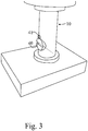
- the tilting can be implemented manually, for example, with the aid of the screw 40 shown connected to the filter 3 in Figure 3 , in which case the wavelength is set to be fixed, or alternatively also with the aid of the motor 205 shown in Figure 9 .
- a locking screw 41 has been added in connection with the adjustment screw 40.
- the tiltable filter 3 can naturally be replaced with some other adjustable interference filter, such as an interference filter based on heating, or an electrically adjusted interference filter.
- the optics in the vicinity of the interference filter, there is preferably a slit mask 4 set transversely to the optical axis 20.
- the slit mask 4 passes light through it only in a direction at right angles to the laser's radiating line and thus limits the laser's feedback to only those modes that radiate at a small angle of, for example, less than six degrees, to the optical axis.
- the power is made to move more to the centre from the edges of the beam.
- the other optics used can, in the case in the example, exploit only the light that is at an angle of less than ⁇ 6 degrees, the rest would be lost.
- the solution according to the invention will operate even without this mask, but the mask improves the end result.
- the beam of rays is guided to a focussing doublet lens 5, which guides the beam of rays 9 on to a semitransparent mirror 6, from which part continue out through the rest of the optics to form the outgoing pulses 14 shown in Figures 1a and 1b .
- An enlarged, nearly sharp image of the surface of the laser is created on the semitransparent mirror. From the semitransparent mirror, some of the radiation energy is reflected in the return direction towards the laser diode. These rays again pass through the interference filter and strike back on the line radiating on the laser's surface, at essentially the same point as they left from. This feedback causes a narrowing of the laser's spectrum and a stabilization of the centre wavelength at the location of the centre wavelength of the interference filter.
- the transmission optics comprises, in addition, a not-shown, typically collimating transmission lens, which is located on the right-hand side of the figure.
- the optical transmission power was 12 mW at a pulse frequency of 10 kHz, the length of the pulses being 100 ns. This corresponds to a pulse energy of 1.2 ⁇ J and a pulse power of about 12 Watts.
- Figure 3 shows in greater detail the manner of adjustment of a tiltable interference filter 3.
- a screw 40 by adjusting the attitude of which the angle of the filter 3 can be controlled, connected mechanically to the filter 3, is brought to the outer surface of the optics.
- the adjustment can also be implemented through a suitable transmission mechanism.
- Figure 4 illustrates the effect of the invention with the aid of a measurement.
- the horizontal axis is the wavelength and the vertical axis the amplitude of the outgoing signal.
- the right-hand shallow signal 30 depicts the power of the outgoing signal 14 without an interference filter 3 and the left-hand narrow peak 31 the spectrum of the outgoing signal correspondingly with a filter 3. In this case, the laser is thus tuned to the wavelength 31.
- the interference filter can be used to make the laser intensity per wavelength unir about ten times higher.
- the reference number 90 is used to show the recommended laser tuning wavelength for maximum transmittance in tropical conditions, in which the atmosphere contains a great deal of water vapour. Thus, at this tuning, it is possible to achieve maximum probing heights.
- the reference number 91 is used to show wavelengths, at which good result can be obtained in measurement of moisture content of lower atmosphere. The backscatter signals measured at the wavelengths of reference number 90 and reference number 91 are then compared with each other.
- Figure 7 shows that, even though the laser's wavelength is adjusted to different wavelengths, the output power of the laser remains more or less the same, according to curve 100.
- the optics according to the invention is serviceable over a sufficiently wide wavelength range and the wavelength adjustment can be performed purely by altering the angle of the filter.
- the optics is also not hypersensitive, for example, to changes in temperature.
- Figure 8 shows graphically two transmittance curves 110 and 111 for an air layer containing water vapour.
- the upper 110 of the curves is calculated at a temperature of 296 K and the lower 111 at a temperature of 266 K, the water-vapour mixing ratio being the same in both cases.
- Figure 11a shows the difference between the curves 110 and 111.
- the moisture content measurement can be implemented by comparing the signals of the wavelengths 112 and 113, in which case at wavelength 113 the water vapour scarcely absorbs the measuring signal and the absorption maximum is obtained at wavelength 112. The amount of water vapour can be determined from the ration between those signals.
- this wavelength 114 can be used as a reference wavelength, if, at the same time, it is wished to determine the temperature of the air layer.
- transmittance at the point 113 is then measured, at which the water has practically no effect on the transmittance, and in addition at point 112, where the effect of the temperature is included and, in addition to these measurements, also at point 114, where the water-vapour mixture ratio can be determined independently of the temperature.
- the measurements are performed by tilting the interference filter 3 sufficiently rapidly with the aid of the motor 205.
- a sufficiently rapid measurement refers to a measurement, in which the measuring interval is at most a few seconds, preferably less than 1 second.
- a measurement of two or more wavelengths can also be implemented with the aid of two laser transmitters 200 and 201 like those depicted and a wavelength-selective semitransparent mirror 202, according to Figure 12.
- Three-point measurement can alternatively be implemented with the aid of two laser transmitters 200 and 201, if a motor-controlled 205 interference filter 3 is included in one of the transmitters.
- the solution according to the invention is particularly advantageous in semiconductor lasers, the pulse power of which is more than 10 W.
Landscapes
- Physics & Mathematics (AREA)
- Engineering & Computer Science (AREA)
- General Physics & Mathematics (AREA)
- Electromagnetism (AREA)
- Environmental & Geological Engineering (AREA)
- Computer Networks & Wireless Communication (AREA)
- Radar, Positioning & Navigation (AREA)
- Remote Sensing (AREA)
- Optics & Photonics (AREA)
- Life Sciences & Earth Sciences (AREA)
- Atmospheric Sciences (AREA)
- Biodiversity & Conservation Biology (AREA)
- Ecology (AREA)
- Environmental Sciences (AREA)
- Condensed Matter Physics & Semiconductors (AREA)
- Plasma & Fusion (AREA)
- Investigating Or Analysing Materials By Optical Means (AREA)
- Length Measuring Devices By Optical Means (AREA)
Description
- The present invention relates to an atmospheric cloud height, humidity profile, or temperature profile measuring method according to the preamble to
Claim 1. - The invention also relates to an atmospheric cloud height or humidity profile measuring apparatus according to the preamble to
Claim 15. - According to the prior art, semiconductor pulse lasers (pulsed diode lasers) are used for cloud probing. In these solutions, the laser's entire wavelength band is sent to the object being measured and the backscattered light is detected. In the detection of the backscattered signal, either completely separate detector optics is used, or alternatively partly the same optics has operated in both the transmission and in the detection.
- A drawback in the prior art is that, despite its good properties, the method is sluggish, due to the non-ideal properties of the transmitting diode laser. The transmission power of a pulsed diode laser is spread over a wide wavelength range. At high transmission powers, a pulse laser also heats up, and heating causes the centre wavelength of the transmission power to shift. The manufacturing tolerance of the centre wavelength of a diode laser is also large. Due to the broad band and instability, the signal-noise ratio has been unsatisfactory.
- In the prior art, test apparatuses are also used, in which the lasers operate in single mode. Such lasers are extremely expensive and, due to the single mode, the output takes place in a line like spectrum, which, in some measurement applications, is hypersensitive to the measuring variables or the properties of the atmosphere.
- Further prior art are presented in the following publications:
ENDEMANN AND R L BYER M: "Simultaneous remote measurements of atmospheric temperature and humidity using a continuously tunable IR lidar", APPLIED OPTICS, OPTICAL SOCIETY OF AMERICA, WASHINGTON, DC; US, vol. 20, no. 18, 15 September 1981 (1981-09-15), pages 3211-3217, XP008161902, ISSN: 0003-6935, DOI: 10.1364/A0.20.003211. In this publication is described a continuously tunable IR lidar. - Amin R. Nehrir ET AL: "Water Vapor Profiling Using a Widely Tunable, Amplified Diode-Laser-Based Differential Absorption Lidar (DIAL)", Journal of Atmospheric and Oceanic Technology, vol. 26, no. 4, 1 April 2009 (2009-04-01), pages 733-745, XP055118881, ISSN: 0739-0572, DOI: 1 0.1175/2008JTECHA 1201.1 In this publication is described a continuously tunable external cavity diode laser (ECDL).
- MATTHEY R ET AL: "Diode laser frequency stabilisation for water-vapour differential absorption sensing", APPLIED PHYSICS B ; LASERSAND OPTICS, SPRINGER, BERLIN, DE, vol. 85, no. 2-3, 18 July 2006 (2006-07-18), pages 477-485, XP019442396, ISSN: 1432-0649, DOI: 10.1007/S00340-006-2358-Z. In this publication is described a low-power continuous-wave laser system for water-vapour sensing applications in the 935-nm region.
-
US 5 457 706 describes a tunable continuous wave (CW) diodepumped thulium holmium yttrium lithium fluoride laser operating at or near room temperature. -
US 2002/054614 describes a wavelength discretely tunable semiconductor laser that addresses wide wavelength tuning range. - The invention is intended to solve at least some of the problems of the prior art described above, and for this purpose to create a completely new type of method and apparatus for the measurement of the atmospheric humidity profile or temperature profile or cloud height.
- The invention is based on using an interference filter in the optics, in order to stabilize the optical power transmitted to the centre frequency of the interference filter. The invention is particularly advantageous when the laser is operating in multimode and the laser's radiating area is line shaped.
- More specifically, the method according to the invention is characterized by what is stated in the characterizing portion of
Claim 1. - For its part, the apparatus according to the invention is characterized by what is stated in the characterizing portion of
Claim 15. - Considerable advantages are gained with the aid of the applications of the invention.
- With the aid of the invention, the signal-noise ratio of atmospheric measurements can be significantly improved, because the signal power being transmitted can be concentrated in a very narrow measuring band.
- By means of an embodiment according to the invention, in which a tiltable interference filter is used, a precise stabilization result can be obtained with the aid of very simple mechanical means.
- By means of an embodiment according to the invention, in which a spatial slit filter is used, the light energy that has passed through the filter can be guided at exactly the desired optical angle.
- Thanks to the multimode, very economical semiconductor laser light sources can be used. Despite the multimode, the spectrum width is suitable for many atmospheric measurement applications.
- In the following, the invention is examined with the aid of examples and with reference to the accompanying drawings.
-
Figure 1a presents schematically one atmosphere measuring apparatus, in which the invention can be applied. -
Figure 1b presents schematically a second atmosphere measuring apparatus, in which the invention can be applied. -
Figure 2 presents a schematic perspective view of the stabilization optics of the laser according to the invention, for an atmospheric measuring apparatus. -
Figure 3 presents a detail of the mechanical construction of the transmission optics according to the invention. -
Figure 4 presents graphically the effect of the solution according to the invention in the transmission optics. -
Figure 5 presents graphically in greater detail the effect of the invention in the transmission optics. -
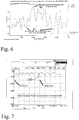
Figure 6 presents graphically alternative (ways) wavelengths, to which the laser can be stabilized. -
Figure 7 presents the output power of the laser, when the interference filter is adjusted to different wavelengths. -
Figure 8 presents graphically two transmission curves, which have been measured at two different temperatures, when there is water vapour in the atmosphere. -
Figure 9 presents an alternative solution according to the invention, in which the measurement of two or three different wavelengths is implemented using two transmitters and a semitransparent mirror. - According to
Figure 1a , the humidity profile and/or temperature and/or cloud height measuring device comprises common transmission andreception optics transmission optics 10 and a light source,laser pulses 14 are sent to the atmosphere and are reflected or scattered back from clouds or other aerosols ormolecules 13 back to the detection optics andapparatus 11. The control andmeasurement logic 12 determines the delays and strengths of the transmitted and received radiation and on their basis the height of theclouds 13 or correspondingly the humidity profile or temperature profile is calculated. The optics according toFigure 1a can be implemented, for example, coaxially, in which case transmission will take place from the centre of the optics and reception from the circumference of the same optics, or alternatively the locations of the transmission and reception can change places. Instead of being coaxial, transmission and reception can be different sectors of the same optics. - According to
Figure 1b , thetransmission optics 10 can be separate from thereception optics 11. The solution of the figure is only an example and, for practical reasons, the transmission optics and reception optics can be close to each other, thus permitting measurement from the greatest possible height range. - In both solutions, the
control device 12 is typically a computer, which measures the time differences and their intensities between the transmission moment of theoutgoing pulses 14 and the reception moment of thesignals 15 arriving, detected by thereception detector 11. This technique will be known to one skilled in the art and, as such, does not relate to the invention. - According to
Figure 2 , the transmission optics comprises adiode laser 1, which, in a typical embodiment, consists of a laser radiating from one or more line shaped areas. In the figure, the dimensions of thelaser 1 are exaggerated by thecoefficient 10, in order to clarify the figure. A single-line laser source 1 is particularly suitable for the detection of atmospheric humidity profiles, whereas with present knowledge a two-line solution, shown inFigure 2 , is more advantageous for cloud-height measurement. In this example case, the laser's spectrum consists of two narrow lines. The length of the entire optics is about 40 - 60 mm. In the solution according toFigure 2 , the optical axis is depicted with thereference number 20. Thus, in the figure twolaser sources 1 are used to form two pulsed beams ofrays 9, coming from a line shaped area, which, in this embodiment, are guided to anaspheric lens 2, which makes the rays at least substantially parallel. After thelens 2, the beam ofrays 9 is guided through a slit mask 4 to aninterference filter 3, which, in the solution of the figure, is a tiltable thin-film filter. By tilting the filter, the angle of incidence of the beam of rays relative to the filter changes and the filter's centre wavelength can, as is known, be changed in this manner. Due to the multi-layer structure of thefilter 3, its tilting reduces the wavelength that passes through the filter. The tilting can be implemented manually, for example, with the aid of thescrew 40 shown connected to thefilter 3 inFigure 3 , in which case the wavelength is set to be fixed, or alternatively also with the aid of themotor 205 shown inFigure 9 . In the solution ofFigure 3 , alocking screw 41 has been added in connection with theadjustment screw 40. Thetiltable filter 3 can naturally be replaced with some other adjustable interference filter, such as an interference filter based on heating, or an electrically adjusted interference filter. - In the optics, in the vicinity of the interference filter, there is preferably a slit mask 4 set transversely to the
optical axis 20. The slit mask 4 passes light through it only in a direction at right angles to the laser's radiating line and thus limits the laser's feedback to only those modes that radiate at a small angle of, for example, less than six degrees, to the optical axis. By means of this slit filter, the power is made to move more to the centre from the edges of the beam. The other optics used can, in the case in the example, exploit only the light that is at an angle of less than ±6 degrees, the rest would be lost. The solution according to the invention will operate even without this mask, but the mask improves the end result. - Next, the beam of rays is guided to a focussing doublet lens 5, which guides the beam of
rays 9 on to asemitransparent mirror 6, from which part continue out through the rest of the optics to form theoutgoing pulses 14 shown inFigures 1a and 1b . An enlarged, nearly sharp image of the surface of the laser is created on the semitransparent mirror. From the semitransparent mirror, some of the radiation energy is reflected in the return direction towards the laser diode. These rays again pass through the interference filter and strike back on the line radiating on the laser's surface, at essentially the same point as they left from. This feedback causes a narrowing of the laser's spectrum and a stabilization of the centre wavelength at the location of the centre wavelength of the interference filter. The transmission optics comprises, in addition, a not-shown, typically collimating transmission lens, which is located on the right-hand side of the figure. In one test solution of the invention, the optical transmission power was 12 mW at a pulse frequency of 10 kHz, the length of the pulses being 100 ns. This corresponds to a pulse energy of 1.2 µJ and a pulse power of about 12 Watts. -
Figure 3 shows in greater detail the manner of adjustment of atiltable interference filter 3. Ascrew 40, by adjusting the attitude of which the angle of thefilter 3 can be controlled, connected mechanically to thefilter 3, is brought to the outer surface of the optics. Naturally, the adjustment can also be implemented through a suitable transmission mechanism. -
Figure 4 illustrates the effect of the invention with the aid of a measurement. InFigure 4 , the horizontal axis is the wavelength and the vertical axis the amplitude of the outgoing signal. The right-handshallow signal 30 depicts the power of theoutgoing signal 14 without aninterference filter 3 and the left-handnarrow peak 31 the spectrum of the outgoing signal correspondingly with afilter 3. In this case, the laser is thus tuned to thewavelength 31. - As can be seen from the figure, the interference filter can be used to make the laser intensity per wavelength unir about ten times higher.
- In
Figure 5 , the information is shown on a more precise wavelength scale and the centre wavelength is marked with thereference number 50. - According to
Figure 6 , various alternatives exist in terms of the tuning of thefilter 3, always according to the embodiment. Thereference number 90 is used to show the recommended laser tuning wavelength for maximum transmittance in tropical conditions, in which the atmosphere contains a great deal of water vapour. Thus, at this tuning, it is possible to achieve maximum probing heights. Thereference number 91, on the other hand, is used to show wavelengths, at which good result can be obtained in measurement of moisture content of lower atmosphere. The backscatter signals measured at the wavelengths ofreference number 90 andreference number 91 are then compared with each other. -
Figure 7 shows that, even though the laser's wavelength is adjusted to different wavelengths, the output power of the laser remains more or less the same, according tocurve 100. This means that the optics according to the invention is serviceable over a sufficiently wide wavelength range and the wavelength adjustment can be performed purely by altering the angle of the filter. The optics is also not hypersensitive, for example, to changes in temperature. -
Figure 8 shows graphically twotransmittance curves 110 and 111 for an air layer containing water vapour. The upper 110 of the curves is calculated at a temperature of 296 K and the lower 111 at a temperature of 266 K, the water-vapour mixing ratio being the same in both cases. Figure 11a shows the difference between thecurves 110 and 111. As can be seen fromFigure 8 , the moisture content measurement can be implemented by comparing the signals of thewavelengths wavelength 113 the water vapour scarcely absorbs the measuring signal and the absorption maximum is obtained atwavelength 112. The amount of water vapour can be determined from the ration between those signals. - On the one hand, as the temperature at the
water absorption maximum 114 approx. at the wavelength 911 nm has practically no effect on the absorption of water, if the mixture ratio is kept constant, thiswavelength 114 can be used as a reference wavelength, if, at the same time, it is wished to determine the temperature of the air layer. Thus, transmittance at thepoint 113 is then measured, at which the water has practically no effect on the transmittance, and in addition atpoint 112, where the effect of the temperature is included and, in addition to these measurements, also atpoint 114, where the water-vapour mixture ratio can be determined independently of the temperature. The measurements are performed by tilting theinterference filter 3 sufficiently rapidly with the aid of themotor 205. In the present application, the term a sufficiently rapid measurement refers to a measurement, in which the measuring interval is at most a few seconds, preferably less than 1 second. Alternatively, a measurement of two or more wavelengths can also be implemented with the aid of twolaser transmitters semitransparent mirror 202, according to Figure 12. Three-point measurement can alternatively be implemented with the aid of twolaser transmitters interference filter 3 is included in one of the transmitters. - The solution according to the invention is particularly advantageous in semiconductor lasers, the pulse power of which is more than 10 W.
Claims (27)
- Atmospheric cloud height, humidity profile, or temperature profile measuring method, in which method a pulsed laser signal (14) from a light source is transmitted through transmission optics (2, 3, 4, 5, 6) to the atmosphere, and the signal reflected or scattered (15) back from there is detected,
characterized in that- a semiconductor pulsed laser (1) operating in multimode is used as the light source, and- an interference filter (3) is used in the optics in order to stabilize transmitted optical power of the light source to the centre frequency of the interference filter (3). - Method according to Claim 1, characterized in that the interference filter (3) is adjustable.
- Method according to Claim 2, characterized in that the interference filter (3) is adjustable by tilting.
- Method according to Claim 2, characterized in that the interference filter (3) is adjustable by heating.
- Method according to Claim 2, characterized in that the interference filter (3) is an electrically adjustable Fabry-Pérot interference filter.
- Method according to any of the above Claims, characterized in that the interference filter (3) is located at such a place in the transmission optics (2, 3, 4, 5, 6), in which the beam of rays (9) is at least substantially parallel.
- Method according to any of the above Claims, characterized in that a pulsed semiconductor laser (1) radiating from a line shaped area is used as the light source.
- Method according to any of the above Claims, characterized in that one laser (1) radiating from a linear area is used as the light source for the measurement of the atmospheric humidity profile and/or temperature profile.
- Method according to Claim 7, characterized in that at least two lasers (1) radiating from a linear area are used as the light source, for example, for the measurement of cloud height.
- Method according to Claim 3, characterized in that the following elements, listed in the direction of travel of the light from the light source (1), are used as the transmission optics (2, 3, 4, 5, 6):- a collimating lens (2),- the tiltable interference filter (3),- a focussing lens (5), and- a semitransparent mirror (6).
- Method according to Claim 10, characterized in that a narrowish slit filter (4) is used on the surface of the tiltable interference filter (3) to guide the light power at a more acute transmission angle.
- Method according to Claim 10 or 11, characterized in that the interference filter (3) is adjusted with the aid of a motor (205).
- Method according to any of the above Claims, characterized in that measurement is performed as three-point measurement (112, 113, 114) at three different wavelengths, in such a way that one measurement point is a reference point (113), at which humidity has practically no effect, the second point (112) is sensitive to both humidity and temperature, and the third point (114) is sensitive to humidity (114) and temperature in a different way than the second point (112), so that both the humidity and the temperature of the object can be determined.
- Method according to any of the above Claims, characterized in that measurement is performed with the aid of two laser transmitters (200, 201) tuned to a different wavelength and a semitransparent mirror (202), so that the laser transmitters (200, 201) are alternated in the measurement.
- Atmospheric cloud height or humidity profile measuring apparatus, which comprises- a diode pulse laser (1), and- transmission optics (2, 3, 4, 5, 6), by means of which a pulsed and stabilized laser signal (14) can be formed and transmitted on towards clouds, and- means (11, 12) for detecting the signal (15) reflected and scattered back,
characterized in that- the diode pulse laser is a semiconductor laser (1) adapted to operate in multimode, and- the apparatus comprises an interference filter (3) for stabilizing the transmitted laser power of the diode pulse laser (1) at the centre frequency of the interference filter (3). - Apparatus according to Claim 15, characterized in that the interference filter (3) can be adjusted.
- Apparatus according to Claim 16, characterized in that the interference filter (3) can be adjusted by tilting.
- Apparatus according to Claim 16, characterized in that the interference filter (3) can be adjusted by heating.
- Apparatus according to Claim 16, characterized in that the interference filter (3) is an electrically adjustable Fabry-Pérot interference filter (3).
- Apparatus according to any of the above Claims, characterized in that the interference filter (3) is located in the transmission optics (2, 3, 4, 5, 6) in such a place, in which the beam of rays (9) is at least substantially parallel.
- Apparatus according to any of the above Claims, characterized in that the diode laser (1) is radiating from a linear area.
- Apparatus according to Claim 21, characterized in that the diode laser (1) is part of a light source that consists of at least two lasers (1) radiating from a linear area.
- Apparatus according to Claim 17, characterized in that the transmission optics (2, 3, 4, 5, 6) comprise the following elements, listed in the direction of travel of the light from the light source (1):- a collimating lens (2),- the tiltable interference filter (3),- a focussing lens (5), and- a semitransparent mirror (6).
- Apparatus according to Claim 23, characterized in that a narrowish slit filter (4) is used on the surface of the interference filter (3) to guide the fed-back light power at a more acute transmission angle.
- Apparatus according to Claim 23 or 24, characterized in that it comprises a motor (205) for adjusting the interference filter (3).
- Apparatus according to any of the above Claims, characterized in that it comprises means for implementing measurement as three-point measurement (112, 113, 114) at three different wavelengths, in such a way that one measurement point is a reference point (113), in which humidity practically cannot affect, the second point (112) is sensitive to both humidity and temperature, and the third point (114) is sensitive to humidity (114) and temperature in a different way to the second, so that both the humidity and the temperature of the object can be determined.
- Apparatus according to any of the above Claims, characterized in that the apparatus comprises a laser transmitter (200, 201) tuned to two different wavelengths and a semitransparent mirror (202).
Applications Claiming Priority (2)
| Application Number | Priority Date | Filing Date | Title |
|---|---|---|---|
| FI20105476A FI20105476L (en) | 2010-04-30 | 2010-04-30 | Method and equipment for measuring atmospheric humidity or temperature profile or cloud height |
| PCT/FI2011/050382 WO2011135183A1 (en) | 2010-04-30 | 2011-04-28 | Atmospheric humidity or temperature or cloud height measuring method and apparatus |
Publications (3)
| Publication Number | Publication Date |
|---|---|
| EP2564236A1 EP2564236A1 (en) | 2013-03-06 |
| EP2564236A4 EP2564236A4 (en) | 2014-07-02 |
| EP2564236B1 true EP2564236B1 (en) | 2020-02-12 |
Family
ID=42133314
Family Applications (1)
| Application Number | Title | Priority Date | Filing Date |
|---|---|---|---|
| EP11774484.7A Active EP2564236B1 (en) | 2010-04-30 | 2011-04-28 | Atmospheric humidity or temperature or cloud height measuring method and apparatus |
Country Status (5)
| Country | Link |
|---|---|
| US (1) | US9229110B2 (en) |
| EP (1) | EP2564236B1 (en) |
| CN (1) | CN102893177B (en) |
| FI (1) | FI20105476L (en) |
| WO (1) | WO2011135183A1 (en) |
Families Citing this family (9)
| Publication number | Priority date | Publication date | Assignee | Title |
|---|---|---|---|---|
| CN103852809B (en) * | 2014-03-11 | 2016-03-02 | 中国科学院空间科学与应用研究中心 | A kind of ground F-P surveys air-dry interferometer |
| CN104181612B (en) * | 2014-08-13 | 2016-03-30 | 中国人民解放军理工大学 | Cloud method surveyed by a kind of infrared ground of combining with laser |
| US10649072B2 (en) * | 2017-05-10 | 2020-05-12 | Massachusetts Institute Of Technology | LiDAR device based on scanning mirrors array and multi-frequency laser modulation |
| KR102289844B1 (en) | 2019-10-31 | 2021-08-18 | 한국원자력연구원 | On-axial lidar apparatus |
| KR102280189B1 (en) | 2019-10-31 | 2021-07-23 | 한국원자력연구원 | Lidar apparatus |
| CN111223153A (en) * | 2020-01-03 | 2020-06-02 | 上海眼控科技股份有限公司 | Cloud top height calculation method and device, computer equipment and storage medium |
| CN113126121B (en) * | 2021-03-17 | 2021-12-07 | 中国科学院国家空间科学中心 | Middle and high-rise atmospheric wind field measuring device |
| CN113093223A (en) * | 2021-04-12 | 2021-07-09 | 广州降光科技有限公司 | Laser ceilometer |
| CN114167519A (en) * | 2021-12-07 | 2022-03-11 | 北京环境特性研究所 | Atmosphere humidity profile reconstruction method and device based on ground actual measurement air humidity |
Family Cites Families (15)
| Publication number | Priority date | Publication date | Assignee | Title |
|---|---|---|---|---|
| CH613310A5 (en) | 1977-04-01 | 1979-09-14 | Inst Angewandte Physik | |
| CH628139A5 (en) | 1978-08-03 | 1982-02-15 | Fruengel Frank | METHOD AND DEVICE FOR CLOUD HEIGHT MEASUREMENT. |
| SE463952B (en) | 1989-10-13 | 1991-02-11 | Hans Martin | DEVICE TO ENABLE A WAVE STABILIZATION OF A SEMI-ELECTRIC WASTE LIGHTED AND RADIATED |
| US5457706A (en) | 1993-03-30 | 1995-10-10 | The United States Of America As Represented By The Administrator Of The National Aeronautics And Space Administration | Tunable CW diode-pumped Tm,Ho:YLiF4 laser operating at or near room temperature |
| US5767953A (en) * | 1993-04-12 | 1998-06-16 | The Regents Of The University Of California | Light beam range finder |
| US5988862A (en) * | 1996-04-24 | 1999-11-23 | Cyra Technologies, Inc. | Integrated system for quickly and accurately imaging and modeling three dimensional objects |
| US6526071B1 (en) * | 1998-10-16 | 2003-02-25 | New Focus, Inc. | Tunable laser transmitter with internal wavelength grid generators |
| AU3691500A (en) * | 1998-11-25 | 2000-07-03 | University Of New Mexico | Precisely wavelength-tunable and wavelength-switchable narrow linewidth lasers |
| US6556599B1 (en) * | 2000-10-17 | 2003-04-29 | Bookham Technology Plc | External cavity laser using angle-tuned filter and method of making same |
| US20020054614A1 (en) * | 2000-11-07 | 2002-05-09 | Hong Jin | Wavelength discretely tunable semiconductor laser |
| EP1198041A1 (en) * | 2001-05-15 | 2002-04-17 | Agilent Technologies, Inc. (a Delaware corporation) | Linear cavity tunable laser |
| CN1198150C (en) * | 2001-06-20 | 2005-04-20 | 香港城市大学 | Coaxial micropulse lidar system with micro-optical wavefront shaper |
| US6822979B2 (en) | 2001-07-06 | 2004-11-23 | Intel Corporation | External cavity laser with continuous tuning of grid generator |
| US7295582B2 (en) * | 2005-06-30 | 2007-11-13 | Intel Corporation | Thermo-optic tunable laser apparatus |
| US7333184B2 (en) * | 2005-07-01 | 2008-02-19 | Itt Manufacturing Enterprises, Inc. | Ground surface cover type reflectivity variation correction in a differential absorption LIDAR system |
-
2010
- 2010-04-30 FI FI20105476A patent/FI20105476L/en not_active Application Discontinuation
-
2011
- 2011-04-28 EP EP11774484.7A patent/EP2564236B1/en active Active
- 2011-04-28 CN CN201180021793.XA patent/CN102893177B/en active Active
- 2011-04-28 WO PCT/FI2011/050382 patent/WO2011135183A1/en not_active Ceased
- 2011-04-28 US US13/635,363 patent/US9229110B2/en active Active
Non-Patent Citations (1)
| Title |
|---|
| None * |
Also Published As
| Publication number | Publication date |
|---|---|
| WO2011135183A1 (en) | 2011-11-03 |
| FI20105476A0 (en) | 2010-04-30 |
| CN102893177B (en) | 2018-02-02 |
| US9229110B2 (en) | 2016-01-05 |
| CN102893177A (en) | 2013-01-23 |
| EP2564236A1 (en) | 2013-03-06 |
| US20130192342A1 (en) | 2013-08-01 |
| EP2564236A4 (en) | 2014-07-02 |
| FI20105476A7 (en) | 2011-10-31 |
| FI20105476L (en) | 2011-10-31 |
Similar Documents
| Publication | Publication Date | Title |
|---|---|---|
| US9229110B2 (en) | Atmospheric humidity or temperature or cloud height measuring method and apparatus | |
| EP1570293B1 (en) | Laser radar apparatus having multiple output wavelenghts | |
| EP1537442B1 (en) | Coherent differential absorption lidar (dial) | |
| JP6781817B2 (en) | Optical system for detecting the scanning range | |
| EP3956677B1 (en) | Rapidly tuneable diode lidar | |
| WO2007135382A2 (en) | Temperature tunable distributed feedback diode lasers for the generation of thz-radiation by photomixing | |
| CN104596987A (en) | Mid-infrared spectroscopy-based trace gas detection method and device combining long-optical-path open light path with wavelength modulation technique | |
| Barrientos Barria et al. | Simultaneous remote monitoring of atmospheric methane and water vapor using an integrated path DIAL instrument based on a widely tunable optical parametric source | |
| US20180120421A1 (en) | Lidar sensor for detecting an object | |
| Bolduc et al. | Noise-equivalent power characterization of an uncooled microbolometer-based THz imaging camera | |
| EP3557228B1 (en) | Gas analyzer | |
| KR101282494B1 (en) | Doppler lidar apparatus and method for operating doppler lidar apparatus | |
| US4870275A (en) | Circulating raman-media laser radar method and apparatus for remote measurement of gases in the atmosphere | |
| US12339403B2 (en) | Adaptive avalanche photodiode bias set point calibration system and method | |
| CN109283550A (en) | All-solid-state all-day water vapor scanning detection lidar system and detection method | |
| US20260081398A1 (en) | Laser assembly with active pointing compensation during wavelength tuning | |
| CN113412561A (en) | Method and apparatus for characterizing a laser gain chip | |
| KR101814129B1 (en) | Optical Apparatus for Lidar System | |
| CN120016276B (en) | Output wavelength closed-loop adjusting method and system based on negative feedback adjusting device | |
| Diblík et al. | The influence of atmospheric turbulence on the rangefinder laser beam | |
| CA1305767C (en) | Circulating raman-media laser radar method and apparatus for remote measurement of gases in the atmosphere | |
| EP3901615B1 (en) | Gas detecting device | |
| JP2842420B2 (en) | Interference filter temperature controller | |
| JPH0412879B2 (en) | ||
| Cadiou et al. | 2-μm Direct detection differential absorption LIDAR for multi-species atmospheric sensing |
Legal Events
| Date | Code | Title | Description |
|---|---|---|---|
| PUAI | Public reference made under article 153(3) epc to a published international application that has entered the european phase |
Free format text: ORIGINAL CODE: 0009012 |
|
| 17P | Request for examination filed |
Effective date: 20121018 |
|
| AK | Designated contracting states |
Kind code of ref document: A1 Designated state(s): AL AT BE BG CH CY CZ DE DK EE ES FI FR GB GR HR HU IE IS IT LI LT LU LV MC MK MT NL NO PL PT RO RS SE SI SK SM TR |
|
| DAX | Request for extension of the european patent (deleted) | ||
| A4 | Supplementary search report drawn up and despatched |
Effective date: 20140604 |
|
| RIC1 | Information provided on ipc code assigned before grant |
Ipc: G01S 7/481 20060101ALI20140528BHEP Ipc: G01W 1/00 20060101ALI20140528BHEP Ipc: G01S 17/95 20060101AFI20140528BHEP Ipc: H01S 5/40 20060101ALI20140528BHEP |
|
| STAA | Information on the status of an ep patent application or granted ep patent |
Free format text: STATUS: EXAMINATION IS IN PROGRESS |
|
| 17Q | First examination report despatched |
Effective date: 20170609 |
|
| GRAP | Despatch of communication of intention to grant a patent |
Free format text: ORIGINAL CODE: EPIDOSNIGR1 |
|
| STAA | Information on the status of an ep patent application or granted ep patent |
Free format text: STATUS: GRANT OF PATENT IS INTENDED |
|
| INTG | Intention to grant announced |
Effective date: 20190913 |
|
| GRAS | Grant fee paid |
Free format text: ORIGINAL CODE: EPIDOSNIGR3 |
|
| GRAA | (expected) grant |
Free format text: ORIGINAL CODE: 0009210 |
|
| STAA | Information on the status of an ep patent application or granted ep patent |
Free format text: STATUS: THE PATENT HAS BEEN GRANTED |
|
| AK | Designated contracting states |
Kind code of ref document: B1 Designated state(s): AL AT BE BG CH CY CZ DE DK EE ES FI FR GB GR HR HU IE IS IT LI LT LU LV MC MK MT NL NO PL PT RO RS SE SI SK SM TR |
|
| REG | Reference to a national code |
Ref country code: GB Ref legal event code: FG4D |
|
| REG | Reference to a national code |
Ref country code: CH Ref legal event code: EP |
|
| REG | Reference to a national code |
Ref country code: AT Ref legal event code: REF Ref document number: 1232871 Country of ref document: AT Kind code of ref document: T Effective date: 20200215 |
|
| REG | Reference to a national code |
Ref country code: IE Ref legal event code: FG4D |
|
| REG | Reference to a national code |
Ref country code: DE Ref legal event code: R096 Ref document number: 602011064955 Country of ref document: DE |
|
| PG25 | Lapsed in a contracting state [announced via postgrant information from national office to epo] |
Ref country code: RS Free format text: LAPSE BECAUSE OF FAILURE TO SUBMIT A TRANSLATION OF THE DESCRIPTION OR TO PAY THE FEE WITHIN THE PRESCRIBED TIME-LIMIT Effective date: 20200212 Ref country code: NO Free format text: LAPSE BECAUSE OF FAILURE TO SUBMIT A TRANSLATION OF THE DESCRIPTION OR TO PAY THE FEE WITHIN THE PRESCRIBED TIME-LIMIT Effective date: 20200512 Ref country code: FI Free format text: LAPSE BECAUSE OF FAILURE TO SUBMIT A TRANSLATION OF THE DESCRIPTION OR TO PAY THE FEE WITHIN THE PRESCRIBED TIME-LIMIT Effective date: 20200212 |
|
| REG | Reference to a national code |
Ref country code: LT Ref legal event code: MG4D |
|
| REG | Reference to a national code |
Ref country code: NL Ref legal event code: MP Effective date: 20200212 |
|
| PG25 | Lapsed in a contracting state [announced via postgrant information from national office to epo] |
Ref country code: IS Free format text: LAPSE BECAUSE OF FAILURE TO SUBMIT A TRANSLATION OF THE DESCRIPTION OR TO PAY THE FEE WITHIN THE PRESCRIBED TIME-LIMIT Effective date: 20200612 Ref country code: BG Free format text: LAPSE BECAUSE OF FAILURE TO SUBMIT A TRANSLATION OF THE DESCRIPTION OR TO PAY THE FEE WITHIN THE PRESCRIBED TIME-LIMIT Effective date: 20200512 Ref country code: GR Free format text: LAPSE BECAUSE OF FAILURE TO SUBMIT A TRANSLATION OF THE DESCRIPTION OR TO PAY THE FEE WITHIN THE PRESCRIBED TIME-LIMIT Effective date: 20200513 Ref country code: SE Free format text: LAPSE BECAUSE OF FAILURE TO SUBMIT A TRANSLATION OF THE DESCRIPTION OR TO PAY THE FEE WITHIN THE PRESCRIBED TIME-LIMIT Effective date: 20200212 Ref country code: LV Free format text: LAPSE BECAUSE OF FAILURE TO SUBMIT A TRANSLATION OF THE DESCRIPTION OR TO PAY THE FEE WITHIN THE PRESCRIBED TIME-LIMIT Effective date: 20200212 Ref country code: HR Free format text: LAPSE BECAUSE OF FAILURE TO SUBMIT A TRANSLATION OF THE DESCRIPTION OR TO PAY THE FEE WITHIN THE PRESCRIBED TIME-LIMIT Effective date: 20200212 |
|
| PG25 | Lapsed in a contracting state [announced via postgrant information from national office to epo] |
Ref country code: NL Free format text: LAPSE BECAUSE OF FAILURE TO SUBMIT A TRANSLATION OF THE DESCRIPTION OR TO PAY THE FEE WITHIN THE PRESCRIBED TIME-LIMIT Effective date: 20200212 |
|
| PG25 | Lapsed in a contracting state [announced via postgrant information from national office to epo] |
Ref country code: PT Free format text: LAPSE BECAUSE OF FAILURE TO SUBMIT A TRANSLATION OF THE DESCRIPTION OR TO PAY THE FEE WITHIN THE PRESCRIBED TIME-LIMIT Effective date: 20200705 Ref country code: DK Free format text: LAPSE BECAUSE OF FAILURE TO SUBMIT A TRANSLATION OF THE DESCRIPTION OR TO PAY THE FEE WITHIN THE PRESCRIBED TIME-LIMIT Effective date: 20200212 Ref country code: ES Free format text: LAPSE BECAUSE OF FAILURE TO SUBMIT A TRANSLATION OF THE DESCRIPTION OR TO PAY THE FEE WITHIN THE PRESCRIBED TIME-LIMIT Effective date: 20200212 Ref country code: EE Free format text: LAPSE BECAUSE OF FAILURE TO SUBMIT A TRANSLATION OF THE DESCRIPTION OR TO PAY THE FEE WITHIN THE PRESCRIBED TIME-LIMIT Effective date: 20200212 Ref country code: SM Free format text: LAPSE BECAUSE OF FAILURE TO SUBMIT A TRANSLATION OF THE DESCRIPTION OR TO PAY THE FEE WITHIN THE PRESCRIBED TIME-LIMIT Effective date: 20200212 Ref country code: SK Free format text: LAPSE BECAUSE OF FAILURE TO SUBMIT A TRANSLATION OF THE DESCRIPTION OR TO PAY THE FEE WITHIN THE PRESCRIBED TIME-LIMIT Effective date: 20200212 Ref country code: RO Free format text: LAPSE BECAUSE OF FAILURE TO SUBMIT A TRANSLATION OF THE DESCRIPTION OR TO PAY THE FEE WITHIN THE PRESCRIBED TIME-LIMIT Effective date: 20200212 Ref country code: CZ Free format text: LAPSE BECAUSE OF FAILURE TO SUBMIT A TRANSLATION OF THE DESCRIPTION OR TO PAY THE FEE WITHIN THE PRESCRIBED TIME-LIMIT Effective date: 20200212 Ref country code: LT Free format text: LAPSE BECAUSE OF FAILURE TO SUBMIT A TRANSLATION OF THE DESCRIPTION OR TO PAY THE FEE WITHIN THE PRESCRIBED TIME-LIMIT Effective date: 20200212 |
|
| REG | Reference to a national code |
Ref country code: DE Ref legal event code: R097 Ref document number: 602011064955 Country of ref document: DE |
|
| REG | Reference to a national code |
Ref country code: AT Ref legal event code: MK05 Ref document number: 1232871 Country of ref document: AT Kind code of ref document: T Effective date: 20200212 |
|
| PG25 | Lapsed in a contracting state [announced via postgrant information from national office to epo] |
Ref country code: MC Free format text: LAPSE BECAUSE OF FAILURE TO SUBMIT A TRANSLATION OF THE DESCRIPTION OR TO PAY THE FEE WITHIN THE PRESCRIBED TIME-LIMIT Effective date: 20200212 |
|
| REG | Reference to a national code |
Ref country code: CH Ref legal event code: PL |
|
| PLBE | No opposition filed within time limit |
Free format text: ORIGINAL CODE: 0009261 |
|
| STAA | Information on the status of an ep patent application or granted ep patent |
Free format text: STATUS: NO OPPOSITION FILED WITHIN TIME LIMIT |
|
| 26N | No opposition filed |
Effective date: 20201113 |
|
| PG25 | Lapsed in a contracting state [announced via postgrant information from national office to epo] |
Ref country code: IT Free format text: LAPSE BECAUSE OF FAILURE TO SUBMIT A TRANSLATION OF THE DESCRIPTION OR TO PAY THE FEE WITHIN THE PRESCRIBED TIME-LIMIT Effective date: 20200212 Ref country code: LI Free format text: LAPSE BECAUSE OF NON-PAYMENT OF DUE FEES Effective date: 20200430 Ref country code: CH Free format text: LAPSE BECAUSE OF NON-PAYMENT OF DUE FEES Effective date: 20200430 Ref country code: AT Free format text: LAPSE BECAUSE OF FAILURE TO SUBMIT A TRANSLATION OF THE DESCRIPTION OR TO PAY THE FEE WITHIN THE PRESCRIBED TIME-LIMIT Effective date: 20200212 Ref country code: LU Free format text: LAPSE BECAUSE OF NON-PAYMENT OF DUE FEES Effective date: 20200428 |
|
| REG | Reference to a national code |
Ref country code: BE Ref legal event code: MM Effective date: 20200430 |
|
| PG25 | Lapsed in a contracting state [announced via postgrant information from national office to epo] |
Ref country code: PL Free format text: LAPSE BECAUSE OF FAILURE TO SUBMIT A TRANSLATION OF THE DESCRIPTION OR TO PAY THE FEE WITHIN THE PRESCRIBED TIME-LIMIT Effective date: 20200212 Ref country code: BE Free format text: LAPSE BECAUSE OF NON-PAYMENT OF DUE FEES Effective date: 20200430 Ref country code: SI Free format text: LAPSE BECAUSE OF FAILURE TO SUBMIT A TRANSLATION OF THE DESCRIPTION OR TO PAY THE FEE WITHIN THE PRESCRIBED TIME-LIMIT Effective date: 20200212 |
|
| PG25 | Lapsed in a contracting state [announced via postgrant information from national office to epo] |
Ref country code: IE Free format text: LAPSE BECAUSE OF NON-PAYMENT OF DUE FEES Effective date: 20200428 |
|
| PG25 | Lapsed in a contracting state [announced via postgrant information from national office to epo] |
Ref country code: TR Free format text: LAPSE BECAUSE OF FAILURE TO SUBMIT A TRANSLATION OF THE DESCRIPTION OR TO PAY THE FEE WITHIN THE PRESCRIBED TIME-LIMIT Effective date: 20200212 Ref country code: MT Free format text: LAPSE BECAUSE OF FAILURE TO SUBMIT A TRANSLATION OF THE DESCRIPTION OR TO PAY THE FEE WITHIN THE PRESCRIBED TIME-LIMIT Effective date: 20200212 Ref country code: CY Free format text: LAPSE BECAUSE OF FAILURE TO SUBMIT A TRANSLATION OF THE DESCRIPTION OR TO PAY THE FEE WITHIN THE PRESCRIBED TIME-LIMIT Effective date: 20200212 |
|
| PG25 | Lapsed in a contracting state [announced via postgrant information from national office to epo] |
Ref country code: MK Free format text: LAPSE BECAUSE OF FAILURE TO SUBMIT A TRANSLATION OF THE DESCRIPTION OR TO PAY THE FEE WITHIN THE PRESCRIBED TIME-LIMIT Effective date: 20200212 Ref country code: AL Free format text: LAPSE BECAUSE OF FAILURE TO SUBMIT A TRANSLATION OF THE DESCRIPTION OR TO PAY THE FEE WITHIN THE PRESCRIBED TIME-LIMIT Effective date: 20200212 |
|
| PGFP | Annual fee paid to national office [announced via postgrant information from national office to epo] |
Ref country code: GB Payment date: 20260423 Year of fee payment: 16 |
|
| PGFP | Annual fee paid to national office [announced via postgrant information from national office to epo] |
Ref country code: DE Payment date: 20260422 Year of fee payment: 16 |
|
| PGFP | Annual fee paid to national office [announced via postgrant information from national office to epo] |
Ref country code: FR Payment date: 20260420 Year of fee payment: 16 |