EP2563289B1 - Duodenal metabolic stent - Google Patents
Duodenal metabolic stent Download PDFInfo
- Publication number
- EP2563289B1 EP2563289B1 EP11716769.2A EP11716769A EP2563289B1 EP 2563289 B1 EP2563289 B1 EP 2563289B1 EP 11716769 A EP11716769 A EP 11716769A EP 2563289 B1 EP2563289 B1 EP 2563289B1
- Authority
- EP
- European Patent Office
- Prior art keywords
- stent
- endoluminal device
- wires
- sleeve
- region
- Prior art date
- Legal status (The legal status is an assumption and is not a legal conclusion. Google has not performed a legal analysis and makes no representation as to the accuracy of the status listed.)
- Not-in-force
Links
- 0 CCCC(CCC(*C(CC)CC(C)*)C1)C1C(*C[C@@](C)CC*)[C@@]1C(C)C1 Chemical compound CCCC(CCC(*C(CC)CC(C)*)C1)C1C(*C[C@@](C)CC*)[C@@]1C(C)C1 0.000 description 2
Images





Classifications
-
- A—HUMAN NECESSITIES
- A61—MEDICAL OR VETERINARY SCIENCE; HYGIENE
- A61F—FILTERS IMPLANTABLE INTO BLOOD VESSELS; PROSTHESES; DEVICES PROVIDING PATENCY TO, OR PREVENTING COLLAPSING OF, TUBULAR STRUCTURES OF THE BODY, e.g. STENTS; ORTHOPAEDIC, NURSING OR CONTRACEPTIVE DEVICES; FOMENTATION; TREATMENT OR PROTECTION OF EYES OR EARS; BANDAGES, DRESSINGS OR ABSORBENT PADS; FIRST-AID KITS
- A61F2/00—Filters implantable into blood vessels; Prostheses, i.e. artificial substitutes or replacements for parts of the body; Appliances for connecting them with the body; Devices providing patency to, or preventing collapsing of, tubular structures of the body, e.g. stents
- A61F2/82—Devices providing patency to, or preventing collapsing of, tubular structures of the body, e.g. stents
- A61F2/86—Stents in a form characterised by the wire-like elements; Stents in the form characterised by a net-like or mesh-like structure
- A61F2/90—Stents in a form characterised by the wire-like elements; Stents in the form characterised by a net-like or mesh-like structure characterised by a net-like or mesh-like structure
-
- A—HUMAN NECESSITIES
- A61—MEDICAL OR VETERINARY SCIENCE; HYGIENE
- A61F—FILTERS IMPLANTABLE INTO BLOOD VESSELS; PROSTHESES; DEVICES PROVIDING PATENCY TO, OR PREVENTING COLLAPSING OF, TUBULAR STRUCTURES OF THE BODY, e.g. STENTS; ORTHOPAEDIC, NURSING OR CONTRACEPTIVE DEVICES; FOMENTATION; TREATMENT OR PROTECTION OF EYES OR EARS; BANDAGES, DRESSINGS OR ABSORBENT PADS; FIRST-AID KITS
- A61F5/00—Orthopaedic methods or devices for non-surgical treatment of bones or joints; Nursing devices ; Anti-rape devices
- A61F5/0003—Apparatus for the treatment of obesity; Anti-eating devices
- A61F5/0013—Implantable devices or invasive measures
- A61F5/0076—Implantable devices or invasive measures preventing normal digestion, e.g. Bariatric or gastric sleeves
-
- A—HUMAN NECESSITIES
- A61—MEDICAL OR VETERINARY SCIENCE; HYGIENE
- A61F—FILTERS IMPLANTABLE INTO BLOOD VESSELS; PROSTHESES; DEVICES PROVIDING PATENCY TO, OR PREVENTING COLLAPSING OF, TUBULAR STRUCTURES OF THE BODY, e.g. STENTS; ORTHOPAEDIC, NURSING OR CONTRACEPTIVE DEVICES; FOMENTATION; TREATMENT OR PROTECTION OF EYES OR EARS; BANDAGES, DRESSINGS OR ABSORBENT PADS; FIRST-AID KITS
- A61F2/00—Filters implantable into blood vessels; Prostheses, i.e. artificial substitutes or replacements for parts of the body; Appliances for connecting them with the body; Devices providing patency to, or preventing collapsing of, tubular structures of the body, e.g. stents
- A61F2/82—Devices providing patency to, or preventing collapsing of, tubular structures of the body, e.g. stents
- A61F2/848—Devices providing patency to, or preventing collapsing of, tubular structures of the body, e.g. stents having means for fixation to the vessel wall, e.g. barbs
-
- A—HUMAN NECESSITIES
- A61—MEDICAL OR VETERINARY SCIENCE; HYGIENE
- A61F—FILTERS IMPLANTABLE INTO BLOOD VESSELS; PROSTHESES; DEVICES PROVIDING PATENCY TO, OR PREVENTING COLLAPSING OF, TUBULAR STRUCTURES OF THE BODY, e.g. STENTS; ORTHOPAEDIC, NURSING OR CONTRACEPTIVE DEVICES; FOMENTATION; TREATMENT OR PROTECTION OF EYES OR EARS; BANDAGES, DRESSINGS OR ABSORBENT PADS; FIRST-AID KITS
- A61F2/00—Filters implantable into blood vessels; Prostheses, i.e. artificial substitutes or replacements for parts of the body; Appliances for connecting them with the body; Devices providing patency to, or preventing collapsing of, tubular structures of the body, e.g. stents
- A61F2/02—Prostheses implantable into the body
- A61F2/04—Hollow or tubular parts of organs, e.g. bladders, tracheae, bronchi or bile ducts
- A61F2002/045—Stomach, intestines
-
- A—HUMAN NECESSITIES
- A61—MEDICAL OR VETERINARY SCIENCE; HYGIENE
- A61F—FILTERS IMPLANTABLE INTO BLOOD VESSELS; PROSTHESES; DEVICES PROVIDING PATENCY TO, OR PREVENTING COLLAPSING OF, TUBULAR STRUCTURES OF THE BODY, e.g. STENTS; ORTHOPAEDIC, NURSING OR CONTRACEPTIVE DEVICES; FOMENTATION; TREATMENT OR PROTECTION OF EYES OR EARS; BANDAGES, DRESSINGS OR ABSORBENT PADS; FIRST-AID KITS
- A61F2/00—Filters implantable into blood vessels; Prostheses, i.e. artificial substitutes or replacements for parts of the body; Appliances for connecting them with the body; Devices providing patency to, or preventing collapsing of, tubular structures of the body, e.g. stents
- A61F2/82—Devices providing patency to, or preventing collapsing of, tubular structures of the body, e.g. stents
- A61F2002/828—Means for connecting a plurality of stents allowing flexibility of the whole structure
-
- A—HUMAN NECESSITIES
- A61—MEDICAL OR VETERINARY SCIENCE; HYGIENE
- A61F—FILTERS IMPLANTABLE INTO BLOOD VESSELS; PROSTHESES; DEVICES PROVIDING PATENCY TO, OR PREVENTING COLLAPSING OF, TUBULAR STRUCTURES OF THE BODY, e.g. STENTS; ORTHOPAEDIC, NURSING OR CONTRACEPTIVE DEVICES; FOMENTATION; TREATMENT OR PROTECTION OF EYES OR EARS; BANDAGES, DRESSINGS OR ABSORBENT PADS; FIRST-AID KITS
- A61F2220/00—Fixations or connections for prostheses classified in groups A61F2/00 - A61F2/26 or A61F2/82 or A61F9/00 or A61F11/00 or subgroups thereof
- A61F2220/0008—Fixation appliances for connecting prostheses to the body
- A61F2220/0016—Fixation appliances for connecting prostheses to the body with sharp anchoring protrusions, e.g. barbs, pins, spikes
-
- A—HUMAN NECESSITIES
- A61—MEDICAL OR VETERINARY SCIENCE; HYGIENE
- A61F—FILTERS IMPLANTABLE INTO BLOOD VESSELS; PROSTHESES; DEVICES PROVIDING PATENCY TO, OR PREVENTING COLLAPSING OF, TUBULAR STRUCTURES OF THE BODY, e.g. STENTS; ORTHOPAEDIC, NURSING OR CONTRACEPTIVE DEVICES; FOMENTATION; TREATMENT OR PROTECTION OF EYES OR EARS; BANDAGES, DRESSINGS OR ABSORBENT PADS; FIRST-AID KITS
- A61F2220/00—Fixations or connections for prostheses classified in groups A61F2/00 - A61F2/26 or A61F2/82 or A61F9/00 or A61F11/00 or subgroups thereof
- A61F2220/0025—Connections or couplings between prosthetic parts, e.g. between modular parts; Connecting elements
- A61F2220/005—Connections or couplings between prosthetic parts, e.g. between modular parts; Connecting elements using adhesives
-
- A—HUMAN NECESSITIES
- A61—MEDICAL OR VETERINARY SCIENCE; HYGIENE
- A61F—FILTERS IMPLANTABLE INTO BLOOD VESSELS; PROSTHESES; DEVICES PROVIDING PATENCY TO, OR PREVENTING COLLAPSING OF, TUBULAR STRUCTURES OF THE BODY, e.g. STENTS; ORTHOPAEDIC, NURSING OR CONTRACEPTIVE DEVICES; FOMENTATION; TREATMENT OR PROTECTION OF EYES OR EARS; BANDAGES, DRESSINGS OR ABSORBENT PADS; FIRST-AID KITS
- A61F2220/00—Fixations or connections for prostheses classified in groups A61F2/00 - A61F2/26 or A61F2/82 or A61F9/00 or A61F11/00 or subgroups thereof
- A61F2220/0025—Connections or couplings between prosthetic parts, e.g. between modular parts; Connecting elements
- A61F2220/0058—Connections or couplings between prosthetic parts, e.g. between modular parts; Connecting elements soldered or brazed or welded
-
- A—HUMAN NECESSITIES
- A61—MEDICAL OR VETERINARY SCIENCE; HYGIENE
- A61F—FILTERS IMPLANTABLE INTO BLOOD VESSELS; PROSTHESES; DEVICES PROVIDING PATENCY TO, OR PREVENTING COLLAPSING OF, TUBULAR STRUCTURES OF THE BODY, e.g. STENTS; ORTHOPAEDIC, NURSING OR CONTRACEPTIVE DEVICES; FOMENTATION; TREATMENT OR PROTECTION OF EYES OR EARS; BANDAGES, DRESSINGS OR ABSORBENT PADS; FIRST-AID KITS
- A61F2250/00—Special features of prostheses classified in groups A61F2/00 - A61F2/26 or A61F2/82 or A61F9/00 or A61F11/00 or subgroups thereof
- A61F2250/0014—Special features of prostheses classified in groups A61F2/00 - A61F2/26 or A61F2/82 or A61F9/00 or A61F11/00 or subgroups thereof having different values of a given property or geometrical feature, e.g. mechanical property or material property, at different locations within the same prosthesis
- A61F2250/0039—Special features of prostheses classified in groups A61F2/00 - A61F2/26 or A61F2/82 or A61F9/00 or A61F11/00 or subgroups thereof having different values of a given property or geometrical feature, e.g. mechanical property or material property, at different locations within the same prosthesis differing in diameter
Definitions
- US 2002/0052644 A1 discloses a tubular endoluminal vascular prosthesis, useful in treating, for example, an abdominal aortic aneurysm.
- the prosthesis comprises a self-expandable wire support structure having a tubular main body support and first and second branch supports.
- Any other suitable technique which is known in the art or which is subsequently developed may also be used to manufacture the stent(s) 20, 40 of the endoluminal device 10.
- the stent 20 and the at least one sleeve 30 are coextensive along the entire longitudinal length of the endoluminal device 10. In this embodiment, the length of the stent 20 and the length of the sleeve 30 are the same length and equal to the length of the endoluminal device 10. In one embodiment, the stent 20 is disposed within the sleeve 30. In another embodiment, the stent 20 is disposed about the sleeve 30. When the sleeve 30 is disposed within or about the stent 20, the sleeve 30 covers the openings 25 of the stent 20 so that there are no openings in the wall of the endoluminal device 10.
- the stent 20 is formed of a plurality of wires 50 that have been interwoven.
- the wires 50 that are interwoven to form the stent 20 are straight.
- the wires 50 that are interwoven to form the stent 20 have a plurality of undulations.
- wires with a plurality of undulations cover more surface area than wires that are straight.
- a schematic wires with undulations that have been interwoven is shown for example in FIG. 6 .
- the plurality of wires defines a plurality of openings 25.
- the second wires 50b forming the second portion 24 are intertwined with one another so that portions of one second wire 50b are wrapped about portions of another second wire 50b to form a knotted stent portion.
- a knotted stent is shown for example in figures 5A-C of U.S. Patent No. 7,594,928 .
- the first region 22 of the stent 20 is made of a plurality of first wires 50a interwoven to form a first braid and the second region 24 is made of a plurality of second wires 50b interwoven to form a second braid and the first and second regions 22, 24 are engaged to one another to form the stent.
- the first and second regions 22, 24 of the stent 20 are engaged to one another by any suitable means.
- the second region 24 is engaged to the first region 22 by looping a portion of a second wire 50b about one of the first wires 50a.
- each first wire 50a has a first diameter along the length of the wire 50 and each second wires 50b has a second diameter along the length of the wire 50.
- the first section 52 of the wire 50 forms the second region 24 of the stent 20 and the second section 54 of the wire 50 forms the first region 22 of the stent 20.
- the second sections 54 of the wires 50 form the anchoring portion 400 of the endoluminal device 10.
- the stent 20 has a first region and a second region and comprises a plurality of interconnected struts (not shown).
- the struts in the first region have a greater radial force than the struts of the second region of the stent.
- the struts of the first region are wider, thicker, or combinations thereof than the struts of the second region.
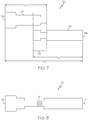
- the stent 20 has a first stent portion 26 and a second stent portion 28 where the first and second stent portions 26, 28 are separate stent portions that overlap one another in a region of overlap 29 to form the stent 20.
- One stent portion 26 forms the first end 21a of the stent 20 and the other stent portion 28 forms the second end 21b of the stent 20.
- the longitudinal length of each stent portion 26, 28 (L 1 ,L 2 ) is less than the longitudinal length of the stent 20 (L 3 ).
- a stent 20 having first and second stent portions 26, 28 is shown schematically in an expanded state in FIG. 7 .
- the first and second stent portions 26, 28 are delivered to the body lumen sequentially. It is within the scope of the invention for the first and second stent portions 26, 28 to be delivered sequentially on the same delivery catheter or different delivery catheters.
- the sleeve 30 is an elastic or conforming polymeric covering.
- the sleeve 30 can be made of a material that is impermeable, semipermeable, selectively permeable, permeable, and any combination thereof.
- Materials that can be used to make the sleeve 30, or sleeve composition include but are not limited to, silicone, polystyrene-polyisobutylene-polystyrene triblock copolymer (SIBS), polyurethane, polyethylene terephthalate (PET), expanded polytetrafluoroethylene (ePTFE), and any combination thereof.
- the endoluminal device 10 has a first sleeve and a second sleeve.
- the first and second sleeves have similar properties.
- both the first and the second sleeves are made from an impermeable material.
- the first and second sleeves have different properties.
- the opening(s) in the sleeve(s) is made by a laser.
- the opening(s) in the sleeve(s) can also be made by cutting, piercing, punching, or any other suitable method.
- the opening 16 in the sleeve(s) 30 has the same shape as the opening 25 defined by the structural members of the stent 20.
- each groove 32 extends along the entire length of the sleeve portion 300.
- the sleeve portion 300 has a variable diameter along the length of the sleeve portion 300. As shown in for example in FIG. 10 , the sleeve portion 300 has grooves 32 which extend about the circumference of the endoluminal device 10.
- FIG. 12 shows an endoluminal device with an anchoring portion 400 that has a plurality of barbs 62.
- the anchoring portion 400 may be a separate anchor 40 and in other embodiments, a portion of the stent 20 forms the anchoring portion.
- the plurality of barbs 62 on the inner surface of the stent 20 engages the stent 20 and the sleeve 30 to one another.
- the plurality of barbs 62 on the outer surface of the stent 20 engages the endoluminal device 10 to the body lumen.
- the stent 20 and the sleeve 30 are mounted onto a mandrel and a covering material is applied to the stent 20 and the sleeve 30 thereby engaging the stent 20 and sleeve 30 together.
- Suitable materials for the covering material include silicone, polystyrene-polyisobutylene-polystyrene triblock copolymer (SIBS), polyurethane, and any combination thereof.
- the sleeve 30 is a preformed tube.
- the ePTFE layer is attached to the stent 20 by an elastomer such as silicone for example.
- the sleeve(s) 30 is attached to the stent 20 by gluing, by welding, by a fastening device, and combinations thereof.
- the sleeve 30 has a plurality of holes 34 and at least one wire 50 is woven through the holes 34 and with one another to form the endoluminal device 10.
- portions of each wire 50 woven through the holes are positioned on an inner surface of the sleeve 30 and other portions of each wire 50 are positioned on the outer surface of the sleeve 30.
- the wires 50 are formed of a stent material.
- Each hole 34 has a size sufficient for a wire to be inserted therethrough.
- a schematic drawing of a sleeve 30 with a plurality of holes 34 is shown for example in Fig. 15 and a schematic drawing of at least one wire 50 interwoven in a portion of the holes 34 of the sleeve is shown for example in FIG. 16 .
- the endoluminal device 10, or portions thereof is delivered to the body lumen by at least one delivery device 70. It is within the scope of the invention for any suitable delivery device to be used to deliver the endoluminal device 10, or portions thereof, as discussed below in greater detail.
- Some delivery devices that can be used include a crochet type delivery device, a delivery device with a double outer tube, and a delivery device with an inner tube and an outer tube.
- a crochet type delivery device that can be used to deliver the endoluminal device includes the Ultraflex delivery device made by Boston Scientific Scimed, Inc.
- a delivery device with a double outer tube is described for example in U.S. 5,919,204 .
- the delivery device further includes a compression sleeve or containment band (not shown).
- the compression sleeve or containment band extends over the stent 20, or the anchor 40, and maintains the stent 20, or the anchor 40, of the endoluminal device 10 in a reduced diameter configuration on the delivery device.
- a delivery device 70 with an outer tube 72 and an inner tube 74 is shown for example by the schematic drawing provided in FIG. 17 .
- the outer tube 72 has a longitudinal length of about 110 cm to about 130 cm.
- the endoluminal device 10, or portions thereof is deployed when the outer tube 72 is retracted away from the endoluminal device 10.
- the anchor 40, the stent 20, the sleeve 30, are disposed about the inner tube 74.
- the stent-sleeve 20-30 is delivered together.
- the stent-sleeve 20-30 is disposed about the inner tube 74.
- the anchor 40 and the stent-sleeve 20-30 are reversibly engaged one to another by barbs 62.
- the stent-sleeve 20-30 can be replaced with another stent-sleeve 20-30, if needed.
- the stent 20 and the sleeve 30 are reversibly engaged one to another by barbs 62.
- the sleeve 30 can be replaced with another sleeve 30.
- the stent-sleeve 20-30 is deployed before an anchor 40 is deployed.
- the anchor 40 has barbs 64 on the outer surface. When the anchor 40 is expanded, the barbs 64 engage the anchor 40 to the endoluminal device 10 and also to the body lumen.
- the stent-sleeve 20-30 is disposed around the anchor 40 when the endoluminal device 10 is deployed in a body lumen. In some embodiments, when the endoluminal device 10 is deployed in a body lumen, a first sleeve 30 is disposed around the stent 20 which is disposed around a second sleeve 30 which is disposed around an anchor 40.
- a portion of the endoluminal device 10 is positioned within the duodenum 104 and another portion of the endoluminal device 10 is positioned within the jejunum 106. In other embodiments, a portion of the endoluminal device 10 is positioned above the gastroesophageal junction. In this embodiment, the endoluminal device 10 extends through the stomach 102, the duodenum 104, and a part of the jejunum 106. In at least one embodiment, an endoluminal device 10 that has a portion extending through the stomach 102 is resistant to the acidic environment of the stomach. In some embodiments, at least a portion of the endoluminal device 10 is made of an acid resistant material.
- the stents 20 and anchor(s) 40 of the endoluminal device 10 may be made from any suitable biocompatible materials including one or more polymers, one or more metals or combinations of polymer(s) and metal(s).
- Polymers that may be used include polyester and polycarbonate copolymers.
- suitable metals include, but are not limited to, titanium, tantalum, platinum, tungsten, gold and alloys of any of the above-mentioned metals.
- suitable alloys include stainless steel, platinum-iridium alloys, cobalt-chromium alloys including Elgiloy and Phynox, MP35N alloy and nickel-titanium alloys, for example, Nitinol.
- the stents 20 and anchor(s) 40 of the endoluminal device 10 may be made of shape memory materials, such as superelastic Nitinol, or may be made of materials which are plastically deformable.
- shape memory materials such as superelastic Nitinol, or may be made of materials which are plastically deformable.
- the stent may be provided with a memorized shape and then deformed to a reduced diameter shape. The stent may restore itself to its memorized shape upon being heated to a transition temperature and having any restraints removed therefrom.
- the stent, the delivery system or other portion of the endoluminal device 10 may include one or more areas, bands, coatings, members, etc. that is (are) detectable by imaging modalities such as X-Ray, MRI, ultrasound, etc. In some embodiments at least a portion of the endoluminal device 10 is at least partially radiopaque.
Landscapes
- Health & Medical Sciences (AREA)
- Engineering & Computer Science (AREA)
- Biomedical Technology (AREA)
- Veterinary Medicine (AREA)
- General Health & Medical Sciences (AREA)
- Public Health (AREA)
- Heart & Thoracic Surgery (AREA)
- Vascular Medicine (AREA)
- Life Sciences & Earth Sciences (AREA)
- Animal Behavior & Ethology (AREA)
- Oral & Maxillofacial Surgery (AREA)
- Transplantation (AREA)
- Cardiology (AREA)
- Child & Adolescent Psychology (AREA)
- Obesity (AREA)
- Nursing (AREA)
- Orthopedic Medicine & Surgery (AREA)
- Media Introduction/Drainage Providing Device (AREA)
Description
- Expandable devices such as stents or other expandable frameworks may be implanted in a variety of body lumens or vessels such as within the vascular system, urinary tracts, gastrointestinal tracts, bile ducts, fallopian tubes, coronary vessels, secondary vessels, etc. Some expandable devices are implanted in a portion of the patient's gastrointestinal tract to treat obesity and medical conditions associated with obesity. Estimates of the incidence of morbid obesity are approximately 2% of the U.S. population and 0.5% worldwide. Recent investigations suggest that the causes of obesity involve a complex interplay of genetic, environmental, psycho-behavioral, endocrine, metabolic, cultural, and socioeconomic factors. Medical conditions associated with obesity include coronary artery disease, hypertension, type II diabetes mellitus, gallstones, nonalcoholic steatohepatitis, pulmonary hypertension, and sleep apnea.
-
US 2002/0052644 A1 discloses a tubular endoluminal vascular prosthesis, useful in treating, for example, an abdominal aortic aneurysm. The prosthesis comprises a self-expandable wire support structure having a tubular main body support and first and second branch supports. -
US 2007/0179590 A1 discloses an intraluminal device, comprising a first expandable stent structure; a second expandable stent structure, wherein said second expandable stent structure is separated by at least one predetermined gap, said at least one predetermined gap being sufficient to dampen external forces encountered by said device in an implanted lumen; and a coating attached to said first expandable stent structure and said second expandable stent structure, wherein said first expandable stent structure comprises a radial expanding force that is different than said second expandable stent structure. - Without limiting the scope of the invention a brief summary of some of the claimed embodiments of the invention is set forth below. Additional details of the summarized embodiments of the invention and/or additional embodiments of the invention may be found in the Detailed Description of the Invention below.
- The invention is defined by claim 1. In at least one embodiment, the invention is directed to an endoluminal device comprising a stent and a sleeve. In some embodiments, the endoluminal device further comprises an anchor. In one embodiment, the endoluminal device is implanted in a portion of the gastrointestinal tract. In some embodiments, the stent has a first region and a second region where the first and second regions have different levels of radial force. In one embodiment, the first region is made from a plurality of first wires having a first diameter and the second region is made from a plurality of second wires having a second diameter which is smaller than the first diameter. In other embodiments, the endoluminal device has at least one engagement mechanism engaging the stent to the sleeve, the endoluminal device to a body lumen, and any combination thereof. In at least one embodiment, the endoluminal device has a wall with at least one opening therein.
- These and other embodiments which characterize the invention are pointed out with particularity in the claims annexed hereto and forming a part hereof. However, for further understanding of the invention, its advantages and objectives obtained by its use, reference can be made to the drawings which form a further part hereof and the accompanying descriptive matter, in which there is illustrated and described an embodiments of the invention.
- A detailed description of the invention is hereafter described with specific reference being made to the drawings.
-
FIG. 1 is a schematic view of a portion of the human gastrointestinal tract. -
FIG. 2 is a schematic view of an endoluminal device. -
FIG. 3 is a schematic view of a stent forming a part of the endoluminal device ofFIG. 2 . -
FIG. 4 is a view of a portion of a stent forming a part of the endoluminal device ofFIG. 2 . -
FIG. 5 is a schematic view of a wire having sections of different diameters which can be used to form a stent of the endoluminal device ofFIG. 2 . -
FIG. 6 is a schematic view of wires having a plurality of undulations which have been interwoven. -
FIG. 7 is a schematic view of a stent forming a part of the endoluminal device ofFIG. 2 . -
FIG. 8 is a schematic view of the endoluminal device ofFIG. 2 in an expanded, deployed state. -
FIG. 9 is a cross-sectional view of a sleeve portion of the endoluminal device ofFIG. 2 . -
FIG. 10 is a schematic view of a sleeve portion of the endoluminal device ofFIG. 2 . -
FIG. 11 is a cross-sectional view of a portion of the endoluminal device ofFIG. 2 having a plurality of barbs. -
FIG. 12 is a cross-sectional view of an embodiment of the endoluminal device ofFIG. 2 . -
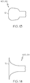
FIG. 13 is a view of an anchoring portion of the endoluminal device ofFIG. 2 . -
FIG. 14 is a view of an anchoring portion of the endoluminal device ofFIG. 2 . -
FIG. 15 is a schematic of a sleeve with a plurality of holes. -
FIG. 16 is a view of the sleeve ofFIG. 15 with a wire interwoven through a portion of the holes. -
FIG. 17 is a schematic of a delivery device for the endoluminal device ofFIG. 2 . - While this invention may be embodied in many different forms, there are described in detail herein specific embodiments of the invention. This description is an exemplification of the principles of the invention and is not intended to limit the invention to the particular embodiments illustrated.
- For the purposes of this disclosure, like reference numerals in the figures shall refer to like features unless otherwise indicated.
- An
endoluminal device 10 is shown schematically inFIG. 2 . In at least one embodiment, theendoluminal device 10 is deployed in a portion of the gastrointestinal tract.FIG. 1 illustrates a portion of the human gastrointestinal tract, including the distal segment of theesophagus 100, thestomach 102, and the small intestine which includes the duodenum 104 (proximate segment of the small intestine), and thejejunum 106. The pyloric part of the stomach leads to theduodenum 104 by way of the gastric outlet orpylorus 108. Thepylorus 108 forms the distal aperture of thestomach 102 and has an enclosing circular layer of muscle which is normally contracted to close the aperture but which relaxes to provide an open but restricted passage. The antrum region of thestomach 102 is adjacent to the pyloric part of the stomach. In some embodiments, theendoluminal device 10 is a duodenal metabolic device. - The
endoluminal device 10 has a longitudinal length (L) between theproximal end 12 and thedistal end 14 of about 30 cm to about 90 cm. Theendoluminal device 10 comprises ananchoring portion 400 and asleeve portion 300. The anchoringportion 400 has a longitudinal length of about 2 cm to about 6 cm. Thesleeve portion 300 has a longitudinal length of about 24 cm to about 88 cm. As used in this application, theendoluminal device 10, and portions comprising theendoluminal device 10 discussed below, e.g. thestent 20, thesleeve 30, and theanchor 40, have an expanded state when it is deployed in a body lumen. - In at least one embodiment, the
endoluminal device 10 has ananchoring portion 400. At least one of the anchoringportions 400 stabilizes the position of theendoluminal device 10 in the body lumen. As shown inFig. 2 , theanchoring portion 400 forms the proximal region of theendoluminal device 10. In at least one embodiment, theanchoring portion 400 has a longitudinal length of about 2 cm to about 6 cm and a diameter in the expanded state of about 30 mm to about 50 mm. In at least one embodiment, the anchoringportion 40 has a radial force that is substantially greater than the radial force of thesleeve portion 300. In some embodiments, the radial force of the anchoringportion 400 is about 10 to about 1,000 times greater than the radial force of thesleeve portion 300. In this application, the term "radial force" refers to the amount of outward pressure exerted on a body lumen by the region when the endoluminal device is deployed in the body lumen. The radial force is defined as the hoop force HF. The hoop force can be described by the following equation, HF= P x 1 x D/2, where P is the pressure exerted by the stent, D is the actual diameter of the stent and 1 is the length of the stent section. For braided stents, the radial force increases with increasing number of wires, increasing wire diameter, and increasing braid angle (α). - In at least one embodiment, the anchoring
portion 400 comprises at least oneanchor 40. In one embodiment, theendoluminal device 10 has oneanchor 40, astent 20, and at least onesleeve 30. In some embodiments, theanchor 40 is an expandable device. In one embodiment, theanchor 40 is a stent. In at least one embodiment, theanchor 40 is laser cut. In one embodiment, the endoluminal device has ananchor stent 40, astent 20, and at least onesleeve 30. It is within the scope of the invention for any stent to be used as ananchor stent 40. In some embodiments, theanchor stent 40 is a balloon expandable stent. In other embodiments, theanchor stent 40 is a self-expanding stent. In at least one embodiment, theanchor 40 has a variable diameter. In some embodiments, theanchor 40 has a proximal end that is positioned at the proximal end of theendoluminal device 10. In other embodiments, theanchor 40 is positioned a distance away from the proximal end of theendoluminal device 10, as shown for example, inFIG. 2 . In this embodiment, the proximal end of theanchor 40 is distal to the proximal end of theendoluminal device 10. - In at least one embodiment, at least a portion of the
stent 20 forms the anchoringportion 400 of theendoluminal device 10. In some embodiments, only a portion of thestent 20 is the anchoringportion 400. In one embodiment, theendoluminal device 10 has astent 20, at least onesleeve 30 and noanchor 40. In other embodiments, theentire stent 20 is the anchoringportion 400. In this embodiment, theendoluminal device 10 has astent 20 and at least onesleeve 30. - In at least one embodiment, the
stent 20 and theanchor 40 are each made of a biocompatible non-degradable material. As is known in the art, some stents have a plurality of cells or openings along the length and circumference of the stent. These cells or openings are defined by a plurality of structural members. Structural members of a stent depend upon the construction of the stent and include for example, struts, connectors, and wires.FIG. 3 showsopenings 25 that are defined bywires 50 forming thestent 20. In some embodiments, thestent 20 has a retrieval loop (not shown). In other embodiments, theanchor 40 has a retrieval loop (not shown). The retrieval loop is a means by which theendoluminal device 10, or a portion or portions thereof, can be repositioned or removed from the body lumen after implantation. Non-limiting examples of suitable materials for thestent 20 and theanchor 40 are provided below. It is within the scope of the invention for thestent 20 to be self-expandable, balloon expandable, or both balloon expandable and self-expandable. - Although some particular methods of making a
stent 20 of theendoluminal device 10 are described in greater detail below, thestent 20 may be made by any method. It is also within the scope of the invention for theanchor stent 40 to be made by any method. For example, the stent(s) 20, 40 may be created by methods including cutting or etching a design from a tubular stock, from a flat sheet which is cut or etched and which is subsequently rolled, or from one or more interwoven wires. In at least one embodiment, thestent stents 20, anchors, or other structures are described inUS 5,759,192 . As
used in this application, the term "interwoven" includes braiding, knotting, knitting, weaving, and combinations thereof. An example of a knotted stent is shown for example in figures 5A-C ofU.S. Patent No. 7,594,928 . - Any other suitable technique which is known in the art or which is subsequently developed may also be used to manufacture the stent(s) 20, 40 of the
endoluminal device 10. - In at least one embodiment, the
stent 20 and the at least onesleeve 30 are coextensive along the entire longitudinal length of theendoluminal device 10. In this embodiment, the length of thestent 20 and the length of thesleeve 30 are the same length and equal to the length of theendoluminal device 10. In one embodiment, thestent 20 is disposed within thesleeve 30. In another embodiment, thestent 20 is disposed about thesleeve 30. When thesleeve 30 is disposed within or about thestent 20, thesleeve 30 covers theopenings 25 of thestent 20 so that there are no openings in the wall of theendoluminal device 10. In some embodiments, thesleeve 30 forms at least a portion of the entire outer surface of theendoluminal device 10. In other embodiments, thesleeve 30 forms at least a portion of the entire inner surface of theendoluminal device 10. In still other embodiments, thestent 20 is sandwiched between a first sleeve 30a and a second sleeve 30b (not shown). In at least one embodiment,sleeve 30 is a liner. - In at least one embodiment, the
stent 20 and the at least onesleeve 30 are coextensive for only a portion of the longitudinal length of theendoluminal device 10. In this embodiment, thestent 20 has a longitudinal length less than the longitudinal length of thesleeve 30. In some embodiments, thestent 20 and thesleeve 30 form theproximal end 12 of theendoluminal device 10 and thesleeve 30 forms thedistal end 14 of theendoluminal device 10. In other examples, thestent 20 forms theproximal end 12 of theendoluminal device 10 and thesleeve 30 forms thedistal end 14 of theendoluminal device 10. In at least one embodiment, the outer surface of thesleeve 30 is attached to the inner surface of thestent 20. - In at least one embodiment, the
stent 20 has afirst end 21 a, asecond end 21b, afirst region 22, and asecond region 24. Examples of astent 20 are shown inFIGS. 3-4 and7-8 .FIGS. 3 and 4 show a schematic example of astent 20 with first andsecond regions second regions second regions first region 22 of thestent 20 has a length of about 20 mm to about 60 mm and a diameter in the expanded state of about 20 mm to about 60 mm. Thesecond region 24 of thestent 20 has a length of about 300 mm to about 900 mm and a diameter in the expanded state of about 15 mm to about 25 mm. In some embodiments, thefirst region 22 of thestent 20 is the anchoringportion 400 of theendoluminal device 10. - In at least one embodiment, the
first region 22 of thestent 20 has a greater radial force than thesecond region 24 of thestent 20. In some embodiments, the lower radial force of thesecond region 24 of thestent 20 allows for peristaltic motion when theendoluminal device 10 is deployed in the body lumen. In other embodiments, the lower radial force of thesecond region 24 of thestent 20 prevents blockage of the bile duct when theendoluminal device 10 is implanted in the gastrointestinal tract. In one embodiment, thesecond region 24 of thestent 20 is positioned at, or adjacent to, the bile duct. - In at least one embodiment, the
stent 20 is formed of a plurality ofwires 50 that have been interwoven. In some embodiments, thewires 50 that are interwoven to form thestent 20 are straight. In other embodiments, thewires 50 that are interwoven to form thestent 20 have a plurality of undulations. In one embodiment, wires with a plurality of undulations cover more surface area than wires that are straight. A schematic wires with undulations that have been interwoven is shown for example inFIG. 6 . In some embodiments, the plurality of wires defines a plurality ofopenings 25. In one embodiment, theopenings 25 defined byadjacent wires 50a in thefirst region 22 have a larger area than theopenings 25 defined byadjacent wires 50b in thesecond region 24. In some embodiments, the density of the wires in thefirst region 22 of the stent is less than the density of the wires in thesecond region 24 of thestent 20. - In at least one embodiment, the plurality of
wires 50 includes a plurality offirst wires 50a and a plurality ofsecond wires 50b. The number offirst wires 50a can be less than, equal to, or greater than, the number ofsecond wires 50b. In some embodiments, the number offirst wires 50 is about 20 wires to about 72 wires. In at least one embodiment, thefirst wires 50a have a first diameter and thesecond wires 50b have a second diameter which is less than the first diameter. In some embodiments, the first diameter is substantially the same along the length of thefirst wire 50a and the second diameter is substantially the same along the length of thesecond wire 50b. In at least one embodiment, thewires 50a that have the first diameter have a greater radial force than thewires 50b that have the second diameter. - In at least one embodiment, the first and
second wires first region 22 of thestent 20 and only thesecond wires 50b form thesecond region 24 of thestent 20, as shown for example inFIG. 3 . Thefirst wires 50a form a first braid and the plurality ofsecond wires 50b is interwoven into the braid formed by thefirst wires 50a. As shown, thesecond wires 50b are interwoven into the first braid so that eachsecond wire 50b is parallel to afirst wire 50a. Thesecond wires 50b extend beyond thefirst region 22 to form thesecond region 24 of thestent 20. In some embodiments, thesecond wires 50b form a braid. In other embodiments, thesecond wires 50b forming thesecond portion 24 are intertwined with one another so that portions of onesecond wire 50b are wrapped about portions of anothersecond wire 50b to form a knotted stent portion. As mentioned above, an example of a knotted stent is shown for example in figures 5A-C ofU.S. Patent No. 7,594,928 . - In at least one embodiment, a
stent 20 having a plurality offirst wires 50a andsecond wires 50b which are braided to form a first andsecond region stent 20, as shown inFIG. 3 , can be made by first braiding thefirst wires 50a to form a first braided stent portion and then incorporating thesecond wires 50b into the first braided stent portion. As shown inFIG. 3 , thesecond wires 50b are interwoven into the first braid so that eachsecond wire 50b is parallel to afirst wire 50a. Thesecond wires 50b can be incorporated into the braid offirst wires 50a by any method and secured to the braidedfirst wires 50a by any method. In one embodiment, thesecond wires 50b are incorporated into the braid offirst wires 50a by hand. Because thesecond wires 50b are a part of both the first andsecond regions stent 20, thesecond wires 50b have a greater length than thefirst wires 50a. - In other embodiments, the
first region 22 of thestent 20 is made of a plurality offirst wires 50a interwoven to form a first braid and thesecond region 24 is made of a plurality ofsecond wires 50b interwoven to form a second braid and the first andsecond regions FIG. 4 . The first andsecond regions stent 20 are engaged to one another by any suitable means. As shown inFIG. 4 , thesecond region 24 is engaged to thefirst region 22 by looping a portion of asecond wire 50b about one of thefirst wires 50a. In some embodiments, eachfirst wire 50a has a first diameter along the length of thewire 50 and eachsecond wires 50b has a second diameter along the length of thewire 50. - In at least one embodiment, the braid angles α of the
wires 50 forming the first andsecond regions stent 20 are matched so that the stent can be compressed for delivery to a body lumen. Thus, the braid angle α in thefirst region 22 is the same as the braid angle α of thesecond region 24 of thestent 20. - In at least one embodiment, the
wire 50 has at least onefirst section 52 with a first diameter and asecond section 54 with a second diameter greater than the first diameter. In some embodiments, the first diameter is about 0.0127 to about 0.1524 mm (about 0.0005 to about 0.006 inches) and the second diameter is about 0.2032 to about 0.508 mm (about 0.008 to about 0.02 inches) In at least one embodiment, the first diameter is substantially the same along the length of thefirst section 52 of thewire 50 and the second diameter is substantially the same along the length of thesecond section 54 of thewire 50. In at least one embodiment, thewire 50 at least onefirst section 52 with a first diameter and asecond section 54 with a second diameter is made by partial drawing, chemical or electrochemical etching, centerless grinding, or any other technology. - In at least one embodiment, the
first section 52 of thewire 50 forms thesecond region 24 of thestent 20 and thesecond section 54 of thewire 50 forms thefirst region 22 of thestent 20. In some embodiments, thesecond sections 54 of thewires 50 form the anchoringportion 400 of theendoluminal device 10. - As shown in
FIG. 5 , thewire 50 has twofirst sections 52 and onesecond section 54. However, it is within the scope of the invention for thewire 50 to have only onefirst section 52 and only onesecond section 54. In some embodiments, the length of thesecond section 52 of thewire 50 corresponds to the length of the anchoringportion 400 of theendoluminal device 10. In other embodiments, the position of thesecond section 54 of thewire 50 relative to a first end of thewire 50 corresponds to a predetermined position of thefirst region 22 along the length of thestent 20 after a plurality ofwires 50 have been interwoven to form thefirst region 22 of thestent 20. - In at least one embodiment, the
stent 20 has a first region and a second region and comprises a plurality of interconnected struts (not shown). In some embodiments, the struts in the first region have a greater radial force than the struts of the second region of the stent. In at least one embodiment, the struts of the first region are wider, thicker, or combinations thereof than the struts of the second region. - In at least one embodiment, the
stent 20 has afirst stent portion 26 and asecond stent portion 28 where the first andsecond stent portions overlap 29 to form thestent 20. Onestent portion 26 forms thefirst end 21a of thestent 20 and theother stent portion 28 forms thesecond end 21b of thestent 20. Thus, the longitudinal length of eachstent portion 26, 28 (L1,L2) is less than the longitudinal length of the stent 20 (L3). Astent 20 having first andsecond stent portions FIG. 7 . In some embodiments, the first andsecond stent portions second stent portions - In some embodiments, the
sleeve portion 300 has at least onesleeve 30. In one embodiment, thesleeve 30 is attached to and extends from theanchor 40. In other embodiments, thesleeve portion 300 has at least onesleeve 30 and astent 20. Thesleeve 30 has a minimum longitudinal length equal to the longitudinal length of thesleeve portion 300 and a maximum longitudinal length equal to the longitudinal length of theendoluminal device 10. In at least one embodiment, thesleeve 30 is attached to and extends from thestent 20. In one embodiment, thestent 20 has a shorter longitudinal length than thesleeve 30. In some embodiments, theanchor 40 is disposed within thestent 20. - In at least one embodiment, the
sleeve 30 is an elastic or conforming polymeric covering. Thesleeve 30 can be made of a material that is impermeable, semipermeable, selectively permeable, permeable, and any combination thereof. Materials that can be used to make thesleeve 30, or sleeve composition, include but are not limited to, silicone, polystyrene-polyisobutylene-polystyrene triblock copolymer (SIBS), polyurethane, polyethylene terephthalate (PET), expanded polytetrafluoroethylene (ePTFE), and any combination thereof. In at least one embodiment, theendoluminal device 10 has a first sleeve and a second sleeve. In some embodiments, the first and second sleeves have similar properties. For example, in one embodiment both the first and the second sleeves are made from an impermeable material. In other embodiments, the first and second sleeves have different properties. - In at least one embodiment, the
endoluminal device 10 has at least oneopening 16 about the circumference of theendoluminal device 10.FIG. 8 shows anendoluminal device 10 with a plurality ofopenings 16. Theopening 16 extends from the inner surface of theendoluminal device 10 to the outer surface of theendoluminal device 10. Because theopening 16 is an opening in the wall of theendoluminal device 10, the opening(s) 16 extend through thestent 20, through the sleeve(s) 30, and any combination thereof. In some embodiments, theopening 16 is partially defined by structural members of thestent 20 and by sleeve material. In other embodiments, the opening is partially defined by structural members of thestent 20, by structural members of theanchor 40, and by sleeve material. In at least one embodiment, the first andsecond stent portions opening 16 in the region of overlap 29 (not shown). - In at least one embodiment, the opening(s) in the sleeve(s) is made by a laser. The opening(s) in the sleeve(s) can also be made by cutting, piercing, punching, or any other suitable method. In some embodiments, the
opening 16 in the sleeve(s) 30 has the same shape as theopening 25 defined by the structural members of thestent 20. - In at least one embodiment, the opening(s) 16 provide a passageway for bile to move into the lumen defined by the
endoluminal device 10. In some embodiments, the opening(s) 16 are positioned on the portion of theendoluminal device 10 that will be located adjacent to, or downstream from, the bile duct when theendoluminal device 10 is deployed in the gastrointestinal tract. - In at least one embodiment, the
endoluminal device 10 has a variable diameter along the length of theendoluminal device 10, about the circumference of theendoluminal device 10, and any combination thereof. In some embodiments, theendoluminal device 10 has a variable diameter when it is an expanded state. In one embodiment, the variable diameter anchors the endoluminal device in a body lumen, facilitates the flow of bile, prevents the occlusion of the bile duct, prevents migration of theendoluminal device 10, conforms to the anatomy of the body lumen, and combinations thereof. A schematic view of anendoluminal device 10 with a variable diameter in an expanded state is shown inFIG. 8 . Although theendoluminal device 10 shown inFIG. 8 has four sections (not labeled), that each section have a different diameter than the section(s) immediately adjacent thereto, theendoluminal device 10 can have two, three, four, five, six or more sections with different diameters than the section(s) immediately adjacent thereto. - In some embodiments, the
sleeve portion 300 has a variable diameter about the circumference. In one embodiment, thesleeve portion 300 has at least onegroove 32 thereby providing thesleeve portion 300 with a variable circumferential diameter. An example of asleeve portion 300 withgrooves 32 is shown inFIG. 9 . It is within the scope of the invention for thesleeve portion 300 to have one, two, three, four, five, six, seven, eight, nine, ten ormore grooves 32. In some embodiments, thegrooves 32 are parallel to a longitudinal axis of theendoluminal device 10. In other embodiments, thegrooves 32 are arranged spirally about thesleeve portion 300. In one embodiment, the eachgroove 32 extends along the entire length of thesleeve portion 300. In other embodiments, thesleeve portion 300 has a variable diameter along the length of thesleeve portion 300. As shown in for example inFIG. 10 , thesleeve portion 300 hasgrooves 32 which extend about the circumference of theendoluminal device 10. - In at least one embodiment, the
endoluminal device 10 has at least one engagement mechanism 60. In some embodiments, the engagement mechanism 60 engages theendolumenal device 10 to the body lumen, prevents migration of theendoluminal device 10, engages thestent 20 to thesleeve 30, engages theanchor 40 to thestent 20 and thesleeve 30, and combinations thereof. Engagement mechanisms 60 include for example, variable diameter of theendoluminal device 10; theanchor 40;barbs 62; the shape 64 of the anchoringportion 400; and combinations thereof. - In at least one embodiment, the anchoring
portion 400 has a plurality ofbarbs 62. In some embodiments, theanchor 40 has a plurality ofbarbs 62. In other embodiments, only the proximal region of thestent 20 has a plurality ofbarbs 62. For simplicity, thediscussion regarding barbs 62 will refer tostent 20. However, the same discussion also applies to ananchor 40 that has a plurality ofbarbs 62. It is within the scope of the invention for thebarbs 62 to be integral to thestent 20, or for thebarbs 62 to be attached to thestent 20, and any combination thereof. In some embodiments, thebarbs 62 are sharp bends in thewires 50 interwoven to form theanchor 40 or the proximal region ofstent 20. The plurality ofbarbs 62 may be located on the inner surface of thestent 20, the outer surface of thestent 20, and any combination thereof.FIG. 11 shows astent 20, that has a plurality ofbarbs 62 on both the inner surface and the outer surface. Eachbarb 62 extends away from the surface of thestent 20. In some embodiments, thetip 63 of eachbarb 62 is parallel to the longitudinal axis of theendoluminal device 10. As shown inFIG. 12 , thebarbs 62 on the inner surface of thestent 20 and thebarbs 62 on the outer surface of thestent 20 face in opposite directions (note that the tips of thebarbs 62 face in opposite directions). -
FIG. 12 shows an endoluminal device with an anchoringportion 400 that has a plurality ofbarbs 62. As discussed above, in some embodiments, the anchoringportion 400 may be aseparate anchor 40 and in other embodiments, a portion of thestent 20 forms the anchoring portion. As shown inFIG. 12 , the plurality ofbarbs 62 on the inner surface of thestent 20 engages thestent 20 and thesleeve 30 to one another. The plurality ofbarbs 62 on the outer surface of thestent 20 engages theendoluminal device 10 to the body lumen. In some embodiments, thebarbs 62 of thestent 20 reversibly engage thestent 20 and theendoluminal device 10 to one another, as discussed below in greater detail. In one embodiment, theendoluminal device 10 has only asleeve 30 to which theanchor 40 is reversibly engaged. - In at least one embodiment, the
anchor 40 has a plurality ofbarbs 62. In some embodiments, theanchor 40 is reversibly engaged to a stent-sleeve stent 20 andsleeve 30 that have been engaged to one another before implantation into a body lumen, as discussed below in greater detail. - In other embodiments, the shape 64 of the anchoring
portion 400 is complementary to the shape of the portion of the body lumen at which the anchoringportion 400 of theendoluminal device 10 is to be positioned. In this embodiment, the shape 64 of the anchoringportion 400 engages theendoluminal device 10 to the body lumen, prevents migration of theendoluminal device 10, and combinations thereof. An anchoringportion 400 that is to be located at the duodenal bulb has a shape 64 complementary to the shape of the duodenal bulb, as shown for example inFIG. 13. FIG. 14 shows an example of the shape 64 of an anchoringportion 400 that is to be positioned at the antrum region of thestomach 102. In some embodiments, at least a portion of the anchoringportion 400 has a variable diameter, as shown for example inFIGS. 13 and 14 . In other embodiments, at least a portion of the anchoringportion 400 has a diameter greater than the diameter of the distal end region of theendoluminal device 10. As discussed above, in some embodiments the anchoringportion 400 is aseparate anchor 40. In those embodiments, theanchor 40 has a variable diameter. In other embodiments, a portion of thestent 20 forms the anchoringportion 400. In those embodiments, the portion of thestent 20 forming the anchoringportion 400 has a variable diameter. - In at least one embodiment, the
endoluminal device 10 has at least one radiopaque marker. In some embodiments, the anchoringregion 400 has at least one radiopaque marker. In other embodiments, at least some of thewires 50 forming thestent 20 of the endoluminal device include at least a portion made of radiopaque material. In one embodiment, the radiopaque material forms the core of the wire(s). Wires having a core of radiopaque material, methods of making wires with a core of radiopaque material, and expandable devices made with wires that have a core of radiopaque material are discussed inU.S. 5,679,470 ,U.S. 5,824,077 ,U.S. 6,527,802 ,U.S. 7,101,392 . In one
embodiment, the radiopaque marker(s) aid in positioning theendoluminal device 10 at the desired location in the body lumen. - In at least one embodiment, a
sleeve 30 is attached to thestent 20 discussed above after thestent 20 has been formed and before theendoluminal device 10 is deployed in a body lumen, a stent-sleeve 20-30. In some embodiments, thesleeve 30 is disposed on the outer surface of thestent 20. In one embodiment, thesleeve 30 is formed by dipping thestent 20 into a sleeve composition. Briefly, thestent 20 is mounted onto a coating mandrel and the assembly is dipped into a polymeric solution. Then the solvent of the polymeric solution is evaporated and the polymer is cured. In another embodiment, thesleeve 30 is formed by spraying the sleeve composition onto thestent 20. Briefly, the stent is mounted onto a coating mandrel and the assembly is sprayed with a polymeric solution. Then the solvent of the polymeric solution is evaporated and the polymer cured. As discussed above, the sleeve composition is an elastic covering so that thesleeve 30 expands with thestent 20 as theendoluminal device 10 is deployed in a body lumen. - In at least one embodiment, the
stent 20 and thesleeve 30 are mounted onto a mandrel and a covering material is applied to thestent 20 and thesleeve 30 thereby engaging thestent 20 andsleeve 30 together. Suitable materials for the covering material include silicone, polystyrene-polyisobutylene-polystyrene triblock copolymer (SIBS), polyurethane, and any combination thereof. In some embodiments, thesleeve 30 is a preformed tube. In other embodiments, thesleeve 30 is a sheet of material that is formed into a tube, placed onto the mandrel and the covering material is applied to engage the edges of the sheet of sleeve material together to form atubular sleeve 30 and the covering material is applied to engage thesleeve 30 to thestent 20. In some embodiments, the covering material is applied to the entire length of theendoluminal device 10. In other embodiments, the covering material is applied only to a portion of theendoluminal device 10 to engage thestent 20 and thesleeve 30 together. In at least one embodiment, the sleeve(s) 30 is an ePTFE layer attached to thestent 20. In one embodiment, the ePTFE layer is attached to thestent 20 by an elastomer such as silicone for example. In another embodiment, the sleeve(s) 30 is attached to thestent 20 by gluing, by welding, by a fastening device, and combinations thereof. - In at least one embodiment, the
sleeve 30 has a plurality ofholes 34 and at least onewire 50 is woven through theholes 34 and with one another to form theendoluminal device 10. In this embodiment, portions of eachwire 50 woven through the holes are positioned on an inner surface of thesleeve 30 and other portions of eachwire 50 are positioned on the outer surface of thesleeve 30. In one embodiment, thewires 50 are formed of a stent material. Eachhole 34 has a size sufficient for a wire to be inserted therethrough. A schematic drawing of asleeve 30 with a plurality ofholes 34 is shown for example inFig. 15 and a schematic drawing of at least onewire 50 interwoven in a portion of theholes 34 of the sleeve is shown for example inFIG. 16 . - In some embodiments, the plurality of
holes 34 extends along the entire longitudinal length of thesleeve 30, as shown inFIG. 15 . It is within the scope of the invention for the plurality ofholes 34 to have the same density along the length of thesleeve 30 or for the density of the holes to vary along the length of thesleeve 30. In one embodiment, the sleeve has a first section comprising a plurality of holes at a first density and a second section comprising a plurality of holes at a second density less than the first density. In other embodiments, only a portion of the longitudinal length of thesleeve 30 has a plurality ofholes 34. In one embodiment, only the proximal end region of thesleeve 30 has a plurality ofholes 34 andwires 50 formed of a stent material are woven through theholes 34. In this embodiment, the longitudinal length of thestent portion 20 formed by thewires 50 is less than the longitudinal length of thesleeve 30. - In some embodiments, the plurality of wires interwoven through the plurality of holes in the sleeve comprise a group of first wires with a first radial force and a group of second wires with a second radial force less than the first radial force. In one embodiment the group of first wires are interwoven with the plurality of holes in a proximal end region of the sleeve and the group of second wires are interwoven the plurality of holes in a distal end region of the sleeve. In this embodiment, the proximal end region of the device has a first radial force and the distal end region has a second radial force where the first radial force is greater than the second radial force.
- In other embodiments, the plurality of wires interwoven through the plurality of holes in the sleeve each have a first section with a first diameter and a second section with a second diameter less than the first diameter. In this embodiment, the first sections of each wire is interwoven through the holes of the proximal end region of the sleeve and the second sections of each wire are interwoven through the holes of the distal end region of the sleeve. Wires with first and second sections of different diameters are discussed above.
- In at least one embodiment, at least a portion of a surface of the endoluminal device has a coating. It is within the scope of the invention for the inner surface, the outer surface, and combinations thereof to have a coating. In some embodiments, the coating provides the endoluminal device with an inner surface that promotes the movement of digested material along the endoluminal device. Coatings that promote movement of digested material include silicone. In other embodiments, the coating provides the endoluminal device with an outer surface that reduces migration of the stent thereby anchoring the endoluminal device within the body lumen.
- In some embodiments the coating is applied to the outer surface of the endoluminal device by placing the endoluminal device over a mandrel and applying a coating to the endoluminal device. It is within the scope of the invention for the mandrel to be a rigid mandrel or an inflatable mandrel. In one embodiment, the coating is applied to the outer surface of the endoluminal device after the mandrel, and the endoluminal device positioned thereon, is expanded.
- In at least one embodiment, the
endoluminal device 10, or portions thereof, is delivered to the body lumen by at least onedelivery device 70. It is within the scope of the invention for any suitable delivery device to be used to deliver theendoluminal device 10, or portions thereof, as discussed below in greater detail. Some delivery devices that can be used include a crochet type delivery device, a delivery device with a double outer tube, and a delivery device with an inner tube and an outer tube. A crochet type delivery device that can be used to deliver the endoluminal device includes the Ultraflex delivery device made by Boston Scientific Scimed, Inc. A delivery device with a double outer tube is described for example inU.S. 5,919,204 . - In at least one embodiment, the delivery device further includes a compression sleeve or containment band (not shown). The compression sleeve or containment band extends over the
stent 20, or theanchor 40, and maintains thestent 20, or theanchor 40, of theendoluminal device 10 in a reduced diameter configuration on the delivery device. - A
delivery device 70 with anouter tube 72 and aninner tube 74 is shown for example by the schematic drawing provided inFIG. 17 . Theouter tube 72 has a longitudinal length of about 110 cm to about 130 cm. In some embodiments, theendoluminal device 10, or portions thereof, is deployed when theouter tube 72 is retracted away from theendoluminal device 10. In this embodiment, theanchor 40, thestent 20, thesleeve 30, are disposed about theinner tube 74. In embodiments where the sleeve is attached to the stent before implantation of theendoluminal device 10, the stent-sleeve 20-30 is delivered together. In these embodiments, the stent-sleeve 20-30 is disposed about theinner tube 74. - As discussed above, in some embodiments the
anchor 40 and the stent-sleeve 20-30 are reversibly engaged one to another bybarbs 62. In this embodiment, the stent-sleeve 20-30 can be replaced with another stent-sleeve 20-30, if needed. As discussed above, in other embodiments, thestent 20 and thesleeve 30 are reversibly engaged one to another bybarbs 62. In these embodiments, thesleeve 30 can be replaced with anothersleeve 30. Note that thestent 20 is disposed around thesleeve 30 and that thebarbs 62 maintain the position of thesleeve 30 to thestent 20 until thesleeve 30 is removed from thebarbs 62 of thestent 20. To remove thesleeve 30 from the barbs of thestent 20, the sleeve is moved beyond the tip of thebarbs 62. - In at least one embodiment, the portions of the
endoluminal device 10 are sequentially deployed in the body lumen. In some embodiments, the portions of the endoluminal device are delivered sequentially on the same delivery device. In one embodiment, a delivery device is configured to sequentially deliver thestent 20 and thesleeve 30. In another embodiment, the delivery device is configured to sequentially deliver theanchor 40, thestent 20, and thesleeve 30. In other embodiments, the portions of theendoluminal device 10 are delivered sequentially on different delivery devices. - In at least one embodiment, the
anchor 40 is deployed before theendoluminal device 10, comprising astent 20 and asleeve 30, is deployed. In one embodiment, the sequential deployment of theanchor 40 and theendoluminal device 10, comprising thestent 20 and thesleeve 30, is separated by a period of time so that some tissue ingrowth into theanchor 40 has occurred before theendoluminal device 10 is deployed. In one embodiment, the tissue ingrowth prevents migration of theanchor 40. Some alternative means to secure theanchor 40 to the body lumen before thesleeve 30 is attached thereto include sutures, clips, T-connectors, and any combination thereof.U.S. Patent Nos. 6,740,121 and6,755,869
describe securing a stent to a body lumen. - In at least one embodiment, the stent-sleeve 20-30 is deployed before an
anchor 40 is deployed. In one embodiment, theanchor 40 has barbs 64 on the outer surface. When theanchor 40 is expanded, the barbs 64 engage theanchor 40 to theendoluminal device 10 and also to the body lumen. In at least one embodiment, the stent-sleeve 20-30 is disposed around theanchor 40 when theendoluminal device 10 is deployed in a body lumen. In some embodiments, when theendoluminal device 10 is deployed in a body lumen, afirst sleeve 30 is disposed around thestent 20 which is disposed around asecond sleeve 30 which is disposed around ananchor 40. In other embodiments, when theendoluminal device 10 is deployed in a body lumen, a first sleeve is disposed around thestent 20, which is disposed around theanchor 20. In still other embodiments, when theendoluminal device 10 is deployed in a body lumen, astent 20 is disposed around asleeve 30, which is disposed around ananchor 40. - In other embodiments, the
sleeve 30 is deployed before thestent 20. In one embodiment, thestent 20 has barbs 64 on the outer surface. When thestent 20 is expanded, the barbs 64 engage thestent 20 to thesleeve 30 and also to the body lumen. In this embodiment, thesleeve 30 is disposed around thestent 20 when theendoluminal device 10 is deployed in a body lumen. - In at some embodiments, a portion of the
endoluminal device 10 is positioned within theduodenum 104 and another portion of theendoluminal device 10 is positioned within thejejunum 106. In other embodiments, a portion of theendoluminal device 10 is positioned above the gastroesophageal junction. In this embodiment, theendoluminal device 10 extends through thestomach 102, theduodenum 104, and a part of thejejunum 106. In at least one embodiment, anendoluminal device 10 that has a portion extending through thestomach 102 is resistant to the acidic environment of the stomach. In some embodiments, at least a portion of theendoluminal device 10 is made of an acid resistant material. In one embodiment, at least a portion of theendoluminal device 10 has a coating of an acid resistant material. Non-limiting examples of materials that are resistant to acidic environments (acid resistant materials) include silicone, polystyrene-polyisobutylene-polystyrene triblock copolymer (SIBS), and combinations thereof. In at least one embodiment, theendoluminal device 10 is positioned within the gastrointestinal tract so that the proximal end of theendoluminal device 10 is placed just distal to the papilla of Vaters, i.e. just below the bile duct. - In at least one embodiment, the
endoluminal device 10 is used to treat obesity, complications of obesity, and combinations thereof. In some embodiments, theendoluminal device 10 when implanted in a body lumen results in weight reduction. In at least one embodiment, theendoluminal device 10 is implanted into a portion of the gastrointestinal tract. In some embodiments, theendoluminal device 10 is removed after a predetermined amount of weight has been lost by the patient. - The
stents 20 and anchor(s) 40 of theendoluminal device 10 may be made from any suitable biocompatible materials including one or more polymers, one or more metals or combinations of polymer(s) and metal(s). Polymers that may be used include polyester and polycarbonate copolymers. Examples of suitable metals include, but are not limited to, titanium, tantalum, platinum, tungsten, gold and alloys of any of the above-mentioned metals. Examples of suitable alloys include stainless steel, platinum-iridium alloys, cobalt-chromium alloys including Elgiloy and Phynox, MP35N alloy and nickel-titanium alloys, for example, Nitinol. - The
stents 20 and anchor(s) 40 of theendoluminal device 10 may be made of shape memory materials, such as superelastic Nitinol, or may be made of materials which are plastically deformable. In the case of shape memory materials, the stent may be provided with a memorized shape and then deformed to a reduced diameter shape. The stent may restore itself to its memorized shape upon being heated to a transition temperature and having any restraints removed therefrom. - In some embodiments the stent, the delivery system or other portion of the
endoluminal device 10 may include one or more areas, bands, coatings, members, etc. that is (are) detectable by imaging modalities such as X-Ray, MRI, ultrasound, etc. In some embodiments at least a portion of theendoluminal device 10 is at least partially radiopaque. - In some embodiments at least a portion of the
endoluminal device 10 is configured to include one or more mechanisms for the delivery of a therapeutic agent. Often the agent will be in the form of a coating or other layer (or layers) of material placed on a surface region of at least a portion of theendoluminal device 10 which is adapted to be released at the site of the endoluminal device's implantation or areas adjacent thereto. - A therapeutic agent may be a drug or other pharmaceutical product such as non-genetic agents, genetic agents, cellular material, etc. Some examples of suitable non-genetic therapeutic agents include but are not limited to: anti-thrombogenic agents such as heparin, heparin derivatives, vascular cell growth promoters, growth factor inhibitors, Paclitaxel, etc. Where an agent includes a genetic therapeutic agent, such a genetic agent may include but is not limited to: DNA, RNA and their respective derivatives and/or components; hedgehog proteins, etc. Where a therapeutic agent includes cellular material, the cellular material may include but is not limited to: cells of human origin and/or non-human origin as well as their respective components and/or derivatives thereof. Where the therapeutic agent includes a polymer agent, the polymer agent may be a polystyrene-polyisobutylene-polystyrene triblock copolymer (SIBS), polyethylene oxide, silicone rubber and/or any other suitable substrate.
Claims (14)
- An endoluminal device (10), suitable for implantation in the gastrointestinal tract, the endoluminal device comprising:a stent (20), the stent having a first end (21a) and a second end (21b), the stent comprising:a plurality of interwoven wires (50), the plurality of interwoven wires forming a first region (22) and a second region (24) of the stent, each of the plurality of interwoven wires having a diameter, the diameter of at least some of the wires in the first region being greater than the diameter of the wires in the second region,a plurality of openings (25) between the first and second ends of the stent, the plurality of openings defined by the plurality of interwoven wires; andan expansible sleeve (30), the expansible sleeve attached to the stent so that it extends over at least some of the plurality of openings of the stent;characterized in that the stent (20) has a proximal end and a distal end, the sleeve extending beyond the distal end of the stent (20) so thatthe stent and the sleeve form a proximal end (12) of the endoluminal device and the sleeve forms a distal end (14) of the endoluminal device and that the expansible sleeve (30) has a plurality of grooves (32).
- The endoluminal device of claim 1, wherein the first region (22) has a first radial force and the second region (24) has a second radial force, the second radial force being less than the first radial force.
- The endoluminal device of claim: 1, wherein the density of the plurality of interwoven wires (50) in the first region (22) is greater than the density of the plurality of wires in the second region (24).
- The endoluminal device of claim 1, wherein each of the plurality of interwoven wires (50) has a first section with a first diameter and a second section with a second diameter, the first diameter being greater than the second diameter;
wherein the first sections of the plurality of interwoven wires (50) form the first region (22) of the stent and the second sections of the plurality of interwoven wires form the second region (24) of the stent (20). - The endoluminal device of claim 1, each of the plurality of interwoven wires (50) having a length, the diameter of each of the plurality of interwoven wires being substantially the same along the length of the wire, the plurality of interwoven wires comprising a plurality of first wires and a plurality of second wires, the plurality of first wires having a first diameter, the plurality of second wires having a second diameter, the first diameter greater than the second diameter, wherein the second region of the stent is formed only of the plurality of second wires.
- The endoluminal device of claim 5, the first region of the stent being formed by the plurality of first wires and the plurality of second wires, wherein the plurality of first wires forms a first braid and the plurality of second wires are interwoven into the first braid, the plurality of first wires being a greater number than the plurality of second wires.
- The endoluminal device of claim 5, the first region of the stent being formed only by the plurality of first wires, and wherein the plurality of second wires is engaged to the plurality of first wires.
- The endoluminal device of claim 1, the expansible sleeve (30) being made of an impermeable material.
- The endoluminal device of claim 1, the endoluminal device having a wall, the wall comprising the stent (20) and the expansible sleeve (30), the expansible sleeve comprising at least one opening, the at least one opening of the expansible sleeve being aligned with one of the plurality of openings (25) defined by the plurality of interwoven wires (50) so that the wall of the endoluminal device comprises at least one opening.
- The endoluminal device of claim 1, the endoluminal device having a variable diameter about a circumference of the endoluminal device, a variable diameter along the length of the endoluminal device, and combinations thereof.
- The endoluminal device of claim 1, wherein at least some of the plurality of interwoven wires have a core made of a radiopaque material.
- The endoluminal device of claim 1, the endoluminal device having an engagement mechanism (60), the engagement mechanism engaging the stent (20) to the sleeve (30), the endoluminal device (10) to a body lumen, and any combination thereof.
- The endoluminal device of claim 12, wherein the engagement mechanism (60) is an anchoring portion (400), the anchoring portion having a shape when the endoluminal device is in an expanded state that is complementary to a shape of a portion of the gastrointestinal tract.
- The endoluminal device of claim 13, wherein the at least a portion of the first region of the stent is the anchoring portion (400).
Applications Claiming Priority (2)
| Application Number | Priority Date | Filing Date | Title |
|---|---|---|---|
| US33005010P | 2010-04-30 | 2010-04-30 | |
| PCT/US2011/032889 WO2011136963A1 (en) | 2010-04-30 | 2011-04-18 | Duodenal metabolic stent |
Publications (2)
| Publication Number | Publication Date |
|---|---|
| EP2563289A1 EP2563289A1 (en) | 2013-03-06 |
| EP2563289B1 true EP2563289B1 (en) | 2017-08-09 |
Family
ID=44263239
Family Applications (1)
| Application Number | Title | Priority Date | Filing Date |
|---|---|---|---|
| EP11716769.2A Not-in-force EP2563289B1 (en) | 2010-04-30 | 2011-04-18 | Duodenal metabolic stent |
Country Status (3)
| Country | Link |
|---|---|
| US (3) | US20110270405A1 (en) |
| EP (1) | EP2563289B1 (en) |
| WO (1) | WO2011136963A1 (en) |
Families Citing this family (22)
| Publication number | Priority date | Publication date | Assignee | Title |
|---|---|---|---|---|
| US9526648B2 (en) | 2010-06-13 | 2016-12-27 | Synerz Medical, Inc. | Intragastric device for treating obesity |
| US10010439B2 (en) | 2010-06-13 | 2018-07-03 | Synerz Medical, Inc. | Intragastric device for treating obesity |
| US10420665B2 (en) | 2010-06-13 | 2019-09-24 | W. L. Gore & Associates, Inc. | Intragastric device for treating obesity |
| US8628554B2 (en) | 2010-06-13 | 2014-01-14 | Virender K. Sharma | Intragastric device for treating obesity |
| DE102013100984B4 (en) * | 2013-01-31 | 2019-03-21 | Acandis Gmbh | Grid mesh for a medical implant or instrument, implant and instrument with such a mesh and set with such an implant or instrument |
| US9265635B2 (en) | 2013-03-14 | 2016-02-23 | Boston Scientific Scimed, Inc. | Stent having removable anchoring element |
| US10172735B2 (en) | 2014-04-05 | 2019-01-08 | Rex Medical, L.P | Duodenum sleeve for treating obesity |
| MX2016016493A (en) * | 2014-05-05 | 2017-12-20 | Endosphere Inc | System and method for ups battery monitoring and data analysis. |
| US20160135941A1 (en) * | 2014-06-18 | 2016-05-19 | Xlumena, Inc. | Biliary stents and methods |
| US10117761B2 (en) * | 2014-12-19 | 2018-11-06 | Boston Scientific Scimed, Inc. | Stent with anti-migration features |
| US10130497B2 (en) | 2015-02-20 | 2018-11-20 | Boston Scientific Scimed, Inc. | Stent with retractable anchors |
| US10779980B2 (en) | 2016-04-27 | 2020-09-22 | Synerz Medical, Inc. | Intragastric device for treating obesity |
| US10568754B2 (en) | 2016-05-13 | 2020-02-25 | Boston Scientific Scimed, Inc. | Protective apparatus for use in gastrointestinal tract |
| CN110167492B (en) | 2016-11-09 | 2021-10-12 | 波士顿科学国际有限公司 | Stent anchoring system |
| CN109009568B (en) * | 2017-06-09 | 2023-10-31 | 上海微创心通医疗科技有限公司 | Mitral valve prosthesis, tricuspid valve prosthesis and stent thereof |
| WO2019084136A1 (en) | 2017-10-25 | 2019-05-02 | Boston Scientific Scimed, Inc. | Stent with atraumatic spacer |
| US10888444B2 (en) | 2017-11-01 | 2021-01-12 | Boston Scientific Scimed, Inc. | Esophageal stent including a valve member |
| US11364134B2 (en) * | 2018-02-15 | 2022-06-21 | Vesper Medical, Inc. | Tapering stent |
| US11925570B2 (en) | 2018-12-19 | 2024-03-12 | Boston Scientific Scimed, Inc. | Stent including anti-migration capabilities |
| WO2020257155A1 (en) | 2019-06-17 | 2020-12-24 | Boston Scientific Scimed, Inc. | Covered endoprosthesis with improved branch access |
| US12496200B2 (en) | 2020-06-19 | 2025-12-16 | Massachusetts Institute Of Technology | Kirigami-inspired stents for sustained local delivery of therapeutics |
| CN113925649B (en) * | 2021-09-30 | 2025-01-24 | 艾柯医疗器械(北京)股份有限公司 | Self-expanding vascular stent |
Family Cites Families (42)
| Publication number | Priority date | Publication date | Assignee | Title |
|---|---|---|---|---|
| US7101392B2 (en) | 1992-03-31 | 2006-09-05 | Boston Scientific Corporation | Tubular medical endoprostheses |
| US5306300A (en) * | 1992-09-22 | 1994-04-26 | Berry H Lee | Tubular digestive screen |
| US5630840A (en) | 1993-01-19 | 1997-05-20 | Schneider (Usa) Inc | Clad composite stent |
| FI953472A0 (en) | 1993-01-19 | 1995-07-18 | Schneider Usa Inc | Coated, combined tension frame |
| DK0627201T3 (en) | 1993-06-02 | 1999-04-26 | Schneider Europ Gmbh | Device for releasing a self-expanding endoprosthesis |
| CA2301351C (en) | 1994-11-28 | 2002-01-22 | Advanced Cardiovascular Systems, Inc. | Method and apparatus for direct laser cutting of metal stents |
| US5575818A (en) * | 1995-02-14 | 1996-11-19 | Corvita Corporation | Endovascular stent with locking ring |
| US5769884A (en) * | 1996-06-27 | 1998-06-23 | Cordis Corporation | Controlled porosity endovascular implant |
| US6340367B1 (en) * | 1997-08-01 | 2002-01-22 | Boston Scientific Scimed, Inc. | Radiopaque markers and methods of using the same |
| US6626939B1 (en) * | 1997-12-18 | 2003-09-30 | Boston Scientific Scimed, Inc. | Stent-graft with bioabsorbable structural support |
| US6156064A (en) * | 1998-08-14 | 2000-12-05 | Schneider (Usa) Inc | Stent-graft-membrane and method of making the same |
| US6733523B2 (en) * | 1998-12-11 | 2004-05-11 | Endologix, Inc. | Implantable vascular graft |
| US6673102B1 (en) * | 1999-01-22 | 2004-01-06 | Gore Enterprises Holdings, Inc. | Covered endoprosthesis and delivery system |
| US6585758B1 (en) * | 1999-11-16 | 2003-07-01 | Scimed Life Systems, Inc. | Multi-section filamentary endoluminal stent |
| US6325822B1 (en) * | 2000-01-31 | 2001-12-04 | Scimed Life Systems, Inc. | Braided stent having tapered filaments |
| US6398807B1 (en) * | 2000-01-31 | 2002-06-04 | Scimed Life Systems, Inc. | Braided branching stent, method for treating a lumen therewith, and process for manufacture therefor |
| US6622604B1 (en) * | 2000-01-31 | 2003-09-23 | Scimed Life Systems, Inc. | Process for manufacturing a braided bifurcated stent |
| US6447396B1 (en) * | 2000-10-17 | 2002-09-10 | Nearlife, Inc. | Method and apparatus for coordinating an interactive computer game with a broadcast television program |
| US6675809B2 (en) * | 2001-08-27 | 2004-01-13 | Richard S. Stack | Satiation devices and methods |
| US6790237B2 (en) * | 2001-10-09 | 2004-09-14 | Scimed Life Systems, Inc. | Medical stent with a valve and related methods of manufacturing |
| US6740121B2 (en) | 2001-11-09 | 2004-05-25 | Boston Scientific Corporation | Intragastric stent for duodenum bypass |
| US6755869B2 (en) | 2001-11-09 | 2004-06-29 | Boston Scientific Corporation | Intragastric prosthesis for the treatment of morbid obesity |
| US20030135265A1 (en) * | 2002-01-04 | 2003-07-17 | Stinson Jonathan S. | Prostheses implantable in enteral vessels |
| EP1550477B1 (en) * | 2002-08-23 | 2015-11-04 | National Cerebral and Cardiovascular Center | Stent and process for producing the same |
| US7001425B2 (en) * | 2002-11-15 | 2006-02-21 | Scimed Life Systems, Inc. | Braided stent method for its manufacture |
| AU2003298801B9 (en) * | 2002-12-02 | 2008-07-31 | Gi Dynamics, Inc. | Bariatric sleeve |
| US7438712B2 (en) * | 2003-03-05 | 2008-10-21 | Scimed Life Systems, Inc. | Multi-braid exterior tube |
| US7365834B2 (en) | 2003-06-24 | 2008-04-29 | Kla-Tencor Technologies Corporation | Optical system for detecting anomalies and/or features of surfaces |
| US7815589B2 (en) * | 2003-12-09 | 2010-10-19 | Gi Dynamics, Inc. | Methods and apparatus for anchoring within the gastrointestinal tract |
| WO2008098255A2 (en) * | 2007-02-09 | 2008-08-14 | Taheri Laduca Llc | Apparatus and method for deploying an implantable device within the body |
| DE102005019649A1 (en) * | 2005-04-26 | 2006-11-02 | Alveolus Inc. | Flexible stent for positioning in lumen of esophagus comprises tube and stabilization members defined circumferentially about tube, where each member extends inwardly in tube to define inner diameter that is less than inner diameter of tube |
| US20070179590A1 (en) * | 2005-12-29 | 2007-08-02 | Wenfeng Lu | Hybrid intraluminal device with varying expansion force |
| US7594928B2 (en) | 2006-05-17 | 2009-09-29 | Boston Scientific Scimed, Inc. | Bioabsorbable stents with reinforced filaments |
| US8002731B2 (en) * | 2006-05-30 | 2011-08-23 | Boston Scientific Scimed, Inc. | Anti-obesity stent |
| AU2008211193A1 (en) * | 2007-01-29 | 2008-08-07 | Cook Incorporated | Medical prosthesis and method of production |
| US8568468B2 (en) * | 2007-12-06 | 2013-10-29 | Cook Medical Technologies Llc | Stent-graft comprising at least one reinforced hole |
| US7905915B2 (en) * | 2007-12-27 | 2011-03-15 | Cook Incorporated | Z-stent with incorporated barbs |
| US8317857B2 (en) * | 2008-01-10 | 2012-11-27 | Telesis Research, Llc | Biodegradable self-expanding prosthesis |
| EP2273947B1 (en) * | 2008-04-03 | 2018-05-16 | Cook Medical Technologies LLC | Self cleaning devices and systems |
| US8500821B2 (en) * | 2008-06-20 | 2013-08-06 | Vysera Biomedical Limited | Esophageal valve device for placing in the cardia |
| EP2413849B1 (en) * | 2009-04-03 | 2014-07-02 | Metamodix, Inc. | Modular gastrointestinal prostheses |
| US10052220B2 (en) * | 2009-10-09 | 2018-08-21 | Boston Scientific Scimed, Inc. | Stomach bypass for the treatment of obesity |
-
2011
- 2011-04-18 EP EP11716769.2A patent/EP2563289B1/en not_active Not-in-force
- 2011-04-18 WO PCT/US2011/032889 patent/WO2011136963A1/en not_active Ceased
- 2011-04-18 US US13/088,671 patent/US20110270405A1/en not_active Abandoned
-
2013
- 2013-11-19 US US14/084,073 patent/US10278841B2/en not_active Expired - Fee Related
-
2019
- 2019-03-21 US US16/360,762 patent/US20190216620A1/en not_active Abandoned
Non-Patent Citations (1)
| Title |
|---|
| None * |
Also Published As
| Publication number | Publication date |
|---|---|
| EP2563289A1 (en) | 2013-03-06 |
| US20110270405A1 (en) | 2011-11-03 |
| US10278841B2 (en) | 2019-05-07 |
| US20190216620A1 (en) | 2019-07-18 |
| WO2011136963A1 (en) | 2011-11-03 |
| US20140081416A1 (en) | 2014-03-20 |
Similar Documents
| Publication | Publication Date | Title |
|---|---|---|
| US20190216620A1 (en) | Duodenal metabolic stent | |
| US20130218289A1 (en) | Method and systems for determining preparedness of the uterus for delivery | |
| US11717424B2 (en) | Anti-migration stent with quill filaments | |
| US20250161082A1 (en) | Controlled ingrowth feature for antimigration | |
| US10687967B2 (en) | Stretchable stent and delivery system | |
| EP3265029B1 (en) | Tavi anchoring assist device | |
| US6270524B1 (en) | Flexible, radially expansible luminal prostheses | |
| EP2129327B1 (en) | Vascular prosthesis | |
| US8663309B2 (en) | Asymmetric stent apparatus and method | |
| US10314685B2 (en) | Silicone reflux valve for polymeric stents | |
| JP5719327B2 (en) | Helical stent | |
| US8414639B2 (en) | Closed-cell flexible stent hybrid | |
| US20090149946A1 (en) | Stent having at least one barb and methods of manufacture | |
| WO2008112500A2 (en) | Vascular prosthesis and methods of use | |
| CN111356420B (en) | Noninvasive spacing support | |
| US20080114437A1 (en) | Self-expanding side branch bifurcated stent | |
| US20090259295A1 (en) | Method of Delivering Graft Material Without the Use of a Stent | |
| CN121263139A (en) | Anti-migration double-wall flange bracket |
Legal Events
| Date | Code | Title | Description |
|---|---|---|---|
| PUAI | Public reference made under article 153(3) epc to a published international application that has entered the european phase |
Free format text: ORIGINAL CODE: 0009012 |
|
| 17P | Request for examination filed |
Effective date: 20121106 |
|
| AK | Designated contracting states |
Kind code of ref document: A1 Designated state(s): AL AT BE BG CH CY CZ DE DK EE ES FI FR GB GR HR HU IE IS IT LI LT LU LV MC MK MT NL NO PL PT RO RS SE SI SK SM TR |
|
| DAX | Request for extension of the european patent (deleted) | ||
| 17Q | First examination report despatched |
Effective date: 20160415 |
|
| GRAP | Despatch of communication of intention to grant a patent |
Free format text: ORIGINAL CODE: EPIDOSNIGR1 |
|
| INTG | Intention to grant announced |
Effective date: 20170223 |
|
| GRAS | Grant fee paid |
Free format text: ORIGINAL CODE: EPIDOSNIGR3 |
|
| GRAA | (expected) grant |
Free format text: ORIGINAL CODE: 0009210 |
|
| STAA | Information on the status of an ep patent application or granted ep patent |
Free format text: STATUS: THE PATENT HAS BEEN GRANTED |
|
| AK | Designated contracting states |
Kind code of ref document: B1 Designated state(s): AL AT BE BG CH CY CZ DE DK EE ES FI FR GB GR HR HU IE IS IT LI LT LU LV MC MK MT NL NO PL PT RO RS SE SI SK SM TR |
|
| REG | Reference to a national code |
Ref country code: GB Ref legal event code: FG4D |
|
| REG | Reference to a national code |
Ref country code: CH Ref legal event code: EP Ref country code: AT Ref legal event code: REF Ref document number: 915991 Country of ref document: AT Kind code of ref document: T Effective date: 20170815 |
|
| REG | Reference to a national code |
Ref country code: IE Ref legal event code: FG4D |
|
| REG | Reference to a national code |
Ref country code: DE Ref legal event code: R096 Ref document number: 602011040366 Country of ref document: DE |
|
| REG | Reference to a national code |
Ref country code: NL Ref legal event code: MP Effective date: 20170809 |
|
| REG | Reference to a national code |
Ref country code: LT Ref legal event code: MG4D |
|
| REG | Reference to a national code |
Ref country code: AT Ref legal event code: MK05 Ref document number: 915991 Country of ref document: AT Kind code of ref document: T Effective date: 20170809 |
|
| PG25 | Lapsed in a contracting state [announced via postgrant information from national office to epo] |
Ref country code: AT Free format text: LAPSE BECAUSE OF FAILURE TO SUBMIT A TRANSLATION OF THE DESCRIPTION OR TO PAY THE FEE WITHIN THE PRESCRIBED TIME-LIMIT Effective date: 20170809 Ref country code: NO Free format text: LAPSE BECAUSE OF FAILURE TO SUBMIT A TRANSLATION OF THE DESCRIPTION OR TO PAY THE FEE WITHIN THE PRESCRIBED TIME-LIMIT Effective date: 20171109 Ref country code: FI Free format text: LAPSE BECAUSE OF FAILURE TO SUBMIT A TRANSLATION OF THE DESCRIPTION OR TO PAY THE FEE WITHIN THE PRESCRIBED TIME-LIMIT Effective date: 20170809 Ref country code: HR Free format text: LAPSE BECAUSE OF FAILURE TO SUBMIT A TRANSLATION OF THE DESCRIPTION OR TO PAY THE FEE WITHIN THE PRESCRIBED TIME-LIMIT Effective date: 20170809 Ref country code: NL Free format text: LAPSE BECAUSE OF FAILURE TO SUBMIT A TRANSLATION OF THE DESCRIPTION OR TO PAY THE FEE WITHIN THE PRESCRIBED TIME-LIMIT Effective date: 20170809 Ref country code: SE Free format text: LAPSE BECAUSE OF FAILURE TO SUBMIT A TRANSLATION OF THE DESCRIPTION OR TO PAY THE FEE WITHIN THE PRESCRIBED TIME-LIMIT Effective date: 20170809 Ref country code: LT Free format text: LAPSE BECAUSE OF FAILURE TO SUBMIT A TRANSLATION OF THE DESCRIPTION OR TO PAY THE FEE WITHIN THE PRESCRIBED TIME-LIMIT Effective date: 20170809 |
|
| PG25 | Lapsed in a contracting state [announced via postgrant information from national office to epo] |
Ref country code: LV Free format text: LAPSE BECAUSE OF FAILURE TO SUBMIT A TRANSLATION OF THE DESCRIPTION OR TO PAY THE FEE WITHIN THE PRESCRIBED TIME-LIMIT Effective date: 20170809 Ref country code: GR Free format text: LAPSE BECAUSE OF FAILURE TO SUBMIT A TRANSLATION OF THE DESCRIPTION OR TO PAY THE FEE WITHIN THE PRESCRIBED TIME-LIMIT Effective date: 20171110 Ref country code: BG Free format text: LAPSE BECAUSE OF FAILURE TO SUBMIT A TRANSLATION OF THE DESCRIPTION OR TO PAY THE FEE WITHIN THE PRESCRIBED TIME-LIMIT Effective date: 20171109 Ref country code: PL Free format text: LAPSE BECAUSE OF FAILURE TO SUBMIT A TRANSLATION OF THE DESCRIPTION OR TO PAY THE FEE WITHIN THE PRESCRIBED TIME-LIMIT Effective date: 20170809 Ref country code: RS Free format text: LAPSE BECAUSE OF FAILURE TO SUBMIT A TRANSLATION OF THE DESCRIPTION OR TO PAY THE FEE WITHIN THE PRESCRIBED TIME-LIMIT Effective date: 20170809 Ref country code: ES Free format text: LAPSE BECAUSE OF FAILURE TO SUBMIT A TRANSLATION OF THE DESCRIPTION OR TO PAY THE FEE WITHIN THE PRESCRIBED TIME-LIMIT Effective date: 20170809 Ref country code: IS Free format text: LAPSE BECAUSE OF FAILURE TO SUBMIT A TRANSLATION OF THE DESCRIPTION OR TO PAY THE FEE WITHIN THE PRESCRIBED TIME-LIMIT Effective date: 20171209 |
|
| PG25 | Lapsed in a contracting state [announced via postgrant information from national office to epo] |
Ref country code: RO Free format text: LAPSE BECAUSE OF FAILURE TO SUBMIT A TRANSLATION OF THE DESCRIPTION OR TO PAY THE FEE WITHIN THE PRESCRIBED TIME-LIMIT Effective date: 20170809 Ref country code: CZ Free format text: LAPSE BECAUSE OF FAILURE TO SUBMIT A TRANSLATION OF THE DESCRIPTION OR TO PAY THE FEE WITHIN THE PRESCRIBED TIME-LIMIT Effective date: 20170809 Ref country code: DK Free format text: LAPSE BECAUSE OF FAILURE TO SUBMIT A TRANSLATION OF THE DESCRIPTION OR TO PAY THE FEE WITHIN THE PRESCRIBED TIME-LIMIT Effective date: 20170809 |
|
| REG | Reference to a national code |
Ref country code: DE Ref legal event code: R097 Ref document number: 602011040366 Country of ref document: DE |
|
| PG25 | Lapsed in a contracting state [announced via postgrant information from national office to epo] |
Ref country code: EE Free format text: LAPSE BECAUSE OF FAILURE TO SUBMIT A TRANSLATION OF THE DESCRIPTION OR TO PAY THE FEE WITHIN THE PRESCRIBED TIME-LIMIT Effective date: 20170809 Ref country code: IT Free format text: LAPSE BECAUSE OF FAILURE TO SUBMIT A TRANSLATION OF THE DESCRIPTION OR TO PAY THE FEE WITHIN THE PRESCRIBED TIME-LIMIT Effective date: 20170809 Ref country code: SM Free format text: LAPSE BECAUSE OF FAILURE TO SUBMIT A TRANSLATION OF THE DESCRIPTION OR TO PAY THE FEE WITHIN THE PRESCRIBED TIME-LIMIT Effective date: 20170809 Ref country code: SK Free format text: LAPSE BECAUSE OF FAILURE TO SUBMIT A TRANSLATION OF THE DESCRIPTION OR TO PAY THE FEE WITHIN THE PRESCRIBED TIME-LIMIT Effective date: 20170809 |
|
| PLBE | No opposition filed within time limit |
Free format text: ORIGINAL CODE: 0009261 |
|
| STAA | Information on the status of an ep patent application or granted ep patent |
Free format text: STATUS: NO OPPOSITION FILED WITHIN TIME LIMIT |
|
| 26N | No opposition filed |
Effective date: 20180511 |
|
| PG25 | Lapsed in a contracting state [announced via postgrant information from national office to epo] |
Ref country code: SI Free format text: LAPSE BECAUSE OF FAILURE TO SUBMIT A TRANSLATION OF THE DESCRIPTION OR TO PAY THE FEE WITHIN THE PRESCRIBED TIME-LIMIT Effective date: 20170809 |
|
| PG25 | Lapsed in a contracting state [announced via postgrant information from national office to epo] |
Ref country code: MC Free format text: LAPSE BECAUSE OF FAILURE TO SUBMIT A TRANSLATION OF THE DESCRIPTION OR TO PAY THE FEE WITHIN THE PRESCRIBED TIME-LIMIT Effective date: 20170809 |
|
| REG | Reference to a national code |
Ref country code: CH Ref legal event code: PL |
|
| REG | Reference to a national code |
Ref country code: BE Ref legal event code: MM Effective date: 20180430 |
|
| PG25 | Lapsed in a contracting state [announced via postgrant information from national office to epo] |
Ref country code: LU Free format text: LAPSE BECAUSE OF NON-PAYMENT OF DUE FEES Effective date: 20180418 |
|
| PG25 | Lapsed in a contracting state [announced via postgrant information from national office to epo] |
Ref country code: BE Free format text: LAPSE BECAUSE OF NON-PAYMENT OF DUE FEES Effective date: 20180430 Ref country code: CH Free format text: LAPSE BECAUSE OF NON-PAYMENT OF DUE FEES Effective date: 20180430 Ref country code: LI Free format text: LAPSE BECAUSE OF NON-PAYMENT OF DUE FEES Effective date: 20180430 |
|
| PG25 | Lapsed in a contracting state [announced via postgrant information from national office to epo] |
Ref country code: FR Free format text: LAPSE BECAUSE OF NON-PAYMENT OF DUE FEES Effective date: 20180430 |
|
| PGFP | Annual fee paid to national office [announced via postgrant information from national office to epo] |
Ref country code: IE Payment date: 20190410 Year of fee payment: 9 Ref country code: DE Payment date: 20190402 Year of fee payment: 9 |
|
| PGFP | Annual fee paid to national office [announced via postgrant information from national office to epo] |
Ref country code: GB Payment date: 20190417 Year of fee payment: 9 |
|
| PG25 | Lapsed in a contracting state [announced via postgrant information from national office to epo] |
Ref country code: MT Free format text: LAPSE BECAUSE OF NON-PAYMENT OF DUE FEES Effective date: 20180418 |
|
| PG25 | Lapsed in a contracting state [announced via postgrant information from national office to epo] |
Ref country code: TR Free format text: LAPSE BECAUSE OF FAILURE TO SUBMIT A TRANSLATION OF THE DESCRIPTION OR TO PAY THE FEE WITHIN THE PRESCRIBED TIME-LIMIT Effective date: 20170809 |
|
| PG25 | Lapsed in a contracting state [announced via postgrant information from national office to epo] |
Ref country code: PT Free format text: LAPSE BECAUSE OF FAILURE TO SUBMIT A TRANSLATION OF THE DESCRIPTION OR TO PAY THE FEE WITHIN THE PRESCRIBED TIME-LIMIT Effective date: 20170809 Ref country code: HU Free format text: LAPSE BECAUSE OF FAILURE TO SUBMIT A TRANSLATION OF THE DESCRIPTION OR TO PAY THE FEE WITHIN THE PRESCRIBED TIME-LIMIT; INVALID AB INITIO Effective date: 20110418 |
|
| PG25 | Lapsed in a contracting state [announced via postgrant information from national office to epo] |
Ref country code: MK Free format text: LAPSE BECAUSE OF NON-PAYMENT OF DUE FEES Effective date: 20170809 Ref country code: CY Free format text: LAPSE BECAUSE OF FAILURE TO SUBMIT A TRANSLATION OF THE DESCRIPTION OR TO PAY THE FEE WITHIN THE PRESCRIBED TIME-LIMIT Effective date: 20170809 |
|
| PG25 | Lapsed in a contracting state [announced via postgrant information from national office to epo] |
Ref country code: AL Free format text: LAPSE BECAUSE OF FAILURE TO SUBMIT A TRANSLATION OF THE DESCRIPTION OR TO PAY THE FEE WITHIN THE PRESCRIBED TIME-LIMIT Effective date: 20170809 |
|
| REG | Reference to a national code |
Ref country code: DE Ref legal event code: R119 Ref document number: 602011040366 Country of ref document: DE |
|
| PG25 | Lapsed in a contracting state [announced via postgrant information from national office to epo] |
Ref country code: DE Free format text: LAPSE BECAUSE OF NON-PAYMENT OF DUE FEES Effective date: 20201103 |
|
| GBPC | Gb: european patent ceased through non-payment of renewal fee |
Effective date: 20200418 |
|
| PG25 | Lapsed in a contracting state [announced via postgrant information from national office to epo] |
Ref country code: IE Free format text: LAPSE BECAUSE OF NON-PAYMENT OF DUE FEES Effective date: 20200418 Ref country code: GB Free format text: LAPSE BECAUSE OF NON-PAYMENT OF DUE FEES Effective date: 20200418 |